WO2022186145A1 - 無針注射器に適用される補助具、補助具付き無針注射器、及び皮内への注射方法 - Google Patents
無針注射器に適用される補助具、補助具付き無針注射器、及び皮内への注射方法 Download PDFInfo
- Publication number
- WO2022186145A1 WO2022186145A1 PCT/JP2022/008323 JP2022008323W WO2022186145A1 WO 2022186145 A1 WO2022186145 A1 WO 2022186145A1 JP 2022008323 W JP2022008323 W JP 2022008323W WO 2022186145 A1 WO2022186145 A1 WO 2022186145A1
- Authority
- WO
- WIPO (PCT)
- Prior art keywords
- fold
- injection
- target substance
- clamping piece
- skin
- Prior art date
- Legal status (The legal status is an assumption and is not a legal conclusion. Google has not performed a legal analysis and makes no representation as to the accuracy of the status listed.)
- Ceased
Links
Images







Classifications
-
- A—HUMAN NECESSITIES
- A61—MEDICAL OR VETERINARY SCIENCE; HYGIENE
- A61M—DEVICES FOR INTRODUCING MEDIA INTO, OR ONTO, THE BODY; DEVICES FOR TRANSDUCING BODY MEDIA OR FOR TAKING MEDIA FROM THE BODY; DEVICES FOR PRODUCING OR ENDING SLEEP OR STUPOR
- A61M5/00—Devices for bringing media into the body in a subcutaneous, intra-vascular or intramuscular way; Accessories therefor, e.g. filling or cleaning devices, arm-rests
- A61M5/42—Devices for bringing media into the body in a subcutaneous, intra-vascular or intramuscular way; Accessories therefor, e.g. filling or cleaning devices, arm-rests having means for desensitising skin, for protruding skin to facilitate piercing, or for locating point where body is to be pierced
- A61M5/425—Protruding skin to facilitate piercing, e.g. vacuum cylinders, vein immobilising means
-
- A—HUMAN NECESSITIES
- A61—MEDICAL OR VETERINARY SCIENCE; HYGIENE
- A61M—DEVICES FOR INTRODUCING MEDIA INTO, OR ONTO, THE BODY; DEVICES FOR TRANSDUCING BODY MEDIA OR FOR TAKING MEDIA FROM THE BODY; DEVICES FOR PRODUCING OR ENDING SLEEP OR STUPOR
- A61M5/00—Devices for bringing media into the body in a subcutaneous, intra-vascular or intramuscular way; Accessories therefor, e.g. filling or cleaning devices, arm-rests
- A61M5/178—Syringes
- A61M5/30—Syringes for injection by jet action, without needle, e.g. for use with replaceable ampoules or carpules
-
- A—HUMAN NECESSITIES
- A61—MEDICAL OR VETERINARY SCIENCE; HYGIENE
- A61M—DEVICES FOR INTRODUCING MEDIA INTO, OR ONTO, THE BODY; DEVICES FOR TRANSDUCING BODY MEDIA OR FOR TAKING MEDIA FROM THE BODY; DEVICES FOR PRODUCING OR ENDING SLEEP OR STUPOR
- A61M2209/00—Ancillary equipment
- A61M2209/04—Tools for specific apparatus
-
- A—HUMAN NECESSITIES
- A61—MEDICAL OR VETERINARY SCIENCE; HYGIENE
- A61M—DEVICES FOR INTRODUCING MEDIA INTO, OR ONTO, THE BODY; DEVICES FOR TRANSDUCING BODY MEDIA OR FOR TAKING MEDIA FROM THE BODY; DEVICES FOR PRODUCING OR ENDING SLEEP OR STUPOR
- A61M2209/00—Ancillary equipment
- A61M2209/08—Supports for equipment
- A61M2209/082—Mounting brackets, arm supports for equipment
-
- A—HUMAN NECESSITIES
- A61—MEDICAL OR VETERINARY SCIENCE; HYGIENE
- A61M—DEVICES FOR INTRODUCING MEDIA INTO, OR ONTO, THE BODY; DEVICES FOR TRANSDUCING BODY MEDIA OR FOR TAKING MEDIA FROM THE BODY; DEVICES FOR PRODUCING OR ENDING SLEEP OR STUPOR
- A61M5/00—Devices for bringing media into the body in a subcutaneous, intra-vascular or intramuscular way; Accessories therefor, e.g. filling or cleaning devices, arm-rests
- A61M5/178—Syringes
- A61M5/31—Details
- A61M5/32—Needles; Details of needles pertaining to their connection with syringe or hub; Accessories for bringing the needle into, or holding the needle on, the body; Devices for protection of needles
- A61M5/3287—Accessories for bringing the needle into the body; Automatic needle insertion
Definitions
- the present invention relates to an auxiliary tool applied to a needle-free injector, a needle-free injector with an auxiliary tool, and an intradermal injection method.
- a needle-free syringe without an injection needle is exemplified as a device for injecting an injection target substance such as a drug solution into the skin of a living body or the like.
- an injection target substance pressurized by a driving source such as a compressed gas or a spring is injected toward a target area, and the kinetic energy of the injection target substance is used to push the injection target substance into the skin.
- a configuration for injecting into the inside is adopted.
- Patent Document 1 discloses a technique of forming a cylindrical skirt on the distal end side of a needle-free syringe and arranging an injection tube in a compartment defined by the skirt.
- the air in the compartment is sucked by the suction pump while the open end of the skirt is pressed against the patient's skin. This draws the patient's skin into the compartment and keeps it stable near the tip of the injection tube.
- mammalian skin is generally composed of three layers: the epidermis, which is the outermost layer; the dermis, which is the lower layer of the epidermis; and the subcutaneous tissue, which is the tissue under the dermis.
- an injection target substance such as a vaccine or a gene therapy agent
- a more effective response to a specific injection target substance such as a vaccine or a gene therapy agent can be achieved compared to administration to the subcutaneous tissue or muscle layer. It is known. Therefore, in some cases, it is preferable to inject the injection target substance into the epidermis or dermis with a needle-free injector.
- a needle-free injector it has been difficult to administer drugs to the epidermis and dermis using needle-free syringes, and precise output control and the like according to animal species have been required.
- the technology of the present disclosure has been made in view of the above-described circumstances, and its purpose is to inject an injection target substance into the epidermis and dermis intensively and reliably in intradermal injection of a mammal using a needle-free syringe. It is to provide possible technology.
- the technology of the present disclosure employs the following configuration. That is, the technology of the present disclosure is an auxiliary tool applied to a needle-free injector for injecting an injection target substance intradermally by injecting the injection target substance from an injection port formed in a nozzle part,
- the first clamping piece and the second clamping piece form a fold-shaped part in which the skin is raised in a fold shape by pinching the skin with the mutually opposing clamping surfaces, and a second clamping piece; and a receiving portion provided on the first clamping piece, exposing a fold top vicinity region, which is a region near the fold top portion, of the fold-shaped portion and capable of receiving the nozzle portion. , is an aid.
- the injection target substance is injected from the injection port formed in the nozzle part in a state where the nozzle part of the needleless syringe is received in the receiving part.
- the injection target substance is ejected.
- the region near the top of the folds includes the epidermis and dermis but does not include subcutaneous tissue.
- the fold top vicinity region may be a region located within 3 mm from the fold top to the fold root side in the fold.
- auxiliary tool is provided on the holding surface of at least one of the first holding piece and the second holding piece, and positions the fold top by contacting the fold top of the fold. , may further include a positioning portion.
- the receiving portion may position the injection port with respect to the region near the top of the fold by engaging with the nozzle portion of the needle-free syringe.
- the receiving part is engaged with the nozzle part of the needle-free syringe so that the injection port is within 3 mm from the crest of the fold to the base of the fold.
- the injection port may be positioned so that it is located.
- the receiving part is engaged with the nozzle part of the needle-free syringe, so that the injection port is 1.5 mm from the fold crest to the fold base side in the fold-shaped part.
- the exit may be positioned so that it is within the range.
- the holding surface of the second holding piece may be formed as a flat surface.
- the holding surface of at least one of the first holding piece and the second holding piece is provided with a non-slip portion for suppressing slippage of the fold-shaped portion.
- the assisting tool includes a first extending portion extending from one end of the first clamping piece and having a first gripping portion formed at least in part thereof, and a first holding portion extending from one end of the second clamping piece
- the first holding piece and the second holding piece are opened and closed by manipulating the second extending portion, which extends and at least a part of which is formed with a second gripping portion, and the first gripping portion and the second gripping portion.
- a connecting portion that connects the first extending portion and the second extending portion as follows.
- the first extension portion extends such that the nozzle portion does not interfere with the first extension portion when the nozzle portion is received in the receiving portion. good too.
- the first extension portion extends from the first clamping piece such that the first clamping piece and the first extension portion form a straight line
- the second extending portion may extend from the second clamping piece such that the second clamping piece and the second extending portion form a V shape.
- the technology according to the present disclosure can also be specified as a needle-free syringe with an auxiliary tool. That is, the technology of the present disclosure includes a needleless injector for injecting an injection target substance into the skin by injecting the injection target substance from an injection port formed in a nozzle portion, and an auxiliary tool connected to the needleless syringe. and a needleless syringe with an auxiliary tool, wherein the auxiliary tool is a first clamping piece and a second clamping piece facing each other, and the skin is pinched by the mutually facing clamping surfaces.
- a first clamping piece and a second clamping piece that form a fold-shaped portion in which the skin is raised in a fold shape, and a receiving portion provided in the first clamping piece, wherein the fold-shaped portion of the fold-shaped portion is and a needle-free injector with an auxiliary tool, comprising a receiving part in which the nozzle part is received so that the ejection port faces a region near the top of the pleat, which is a region near the top.
- the technology according to the present disclosure can also be specified as an injection method. That is, the technology according to the present disclosure is an injection method for injecting an injection target substance into the skin of a mammal (excluding humans) by injecting the injection target substance from an injection port formed in a nozzle portion of a needle-free injector.
- An auxiliary tool comprising the needle-free injector, a first clamping piece and a second clamping piece facing each other, and a receiving portion provided on the first clamping piece and capable of receiving the nozzle portion is prepared.
- the skin forms a fold-like portion in which the skin is raised in a fold-like shape.
- the injection method may include injecting the injection target substance from an outlet into the region near the top of the fold.
- the injection target substance in injecting the injection target substance from the injection port, the injection target substance is injected at a position within 3 mm from the fold apex to the fold base side in the folds. You can shoot.
- the injection target in injecting the injection target substance from the injection port, the injection target is positioned within 1.5 mm from the fold top to the fold root side in the folds. You can shoot substances.
- the injection target substance may contain a gene.
- FIG. 1 is an overall view of an assisting device according to Embodiment 1.
- FIG. FIG. 2 is an overall view of a needle-free injector to which the aid according to Embodiment 1 is applied.
- FIG. 3 is a cross-sectional view of a needle-free injector.
- FIG. 4 is a top view of the aid in the closed state.
- FIG. 5 is a side view of the aid in its closed state.
- FIG. 6 is a side view of the aid in its open state.
- FIG. 7 is a flow chart showing procedures of an injection method using the aid according to Embodiment 1.
- FIG. 8 is a cross-sectional view showing a state in which the skin is clamped by the aid according to Embodiment 1.
- FIG. 9 is an enlarged view of FIG. 8.
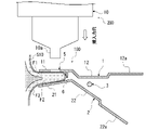
- FIG. 10 is a top view showing a state in which the skin is clamped by the aid according to the first embodiment; 11 is a cross-sectional view showing a state in which the nozzle of the syringe according to Embodiment 1 is received in the receiving portion of the auxiliary tool; FIG. 12 is a top view showing a state in which the nozzle portion of the needle-free syringe is received in the receiving portion of the assisting device according to Embodiment 1.
- FIG. FIG. 13 is a graph showing the light emission amounts of Examples 1 to 4 and Comparative Example. 14 is a cross-sectional view of an auxiliary tool according to Modification 1 of Embodiment 1.
- FIG. 15 is a top view showing a state in which the nozzle portion of the needleless syringe is received in the receiving portion of the auxiliary tool according to Modification 2 of Embodiment 1.
- FIG. 16 is a top view showing a state in which the nozzle portion of the needle-free injector according to the modification is received in the receiving portion of the auxiliary tool according to Modification 3 of Embodiment 1.
- FIG. 17 is an overall view of the aid according to Embodiment 2.
- FIG. FIG. 18 is a cross-sectional view of a needle-free injector with an auxiliary tool according to Embodiment 3.
- FIG. 1 is an overall view of an assisting tool 100 according to Embodiment 1.
- FIG. FIG. 2 is an overall view of a needle-free syringe (hereinafter simply referred to as "syringe") 200 to which the assisting device 100 according to Embodiment 1 is applied.
- the syringe 200 shown in FIG. 2 uses the combustion energy of gunpowder to inject into the skin of a mammal (hereinafter simply referred to as "intradermal”) from an injection port 10b formed in a nozzle portion indicated by reference numeral 10a. It is a needleless syringe that injects a substance.
- the syringe 200 is a device for injecting an injection target substance into the skin without using an injection needle.
- the aid 100 according to the present embodiment enables injection of the injection target substance into the epidermis or dermis by assisting the injection of the injection target substance into the skin of a mammal using the syringe 200 .
- the term "mammal” includes, but is not limited to, humans and mammals other than humans. Mammals other than humans include mice, rats, guinea pigs, hamsters, cows, goats, sheep, pigs, monkeys, dogs, cats and the like.
- distal end and proximal end are used to express relative positional relationships in the longitudinal direction of the syringe 200 .
- the “distal side” refers to the side of the injection port 10b in the longitudinal direction of the syringe 200
- the “basal side” refers to the side opposite to the side of the injection port 10b in the longitudinal direction of the syringe 200 (initiator 101b side, which will be described later).
- the intradermal injection using the syringe 200 does not matter whether the environment is in vivo or in vitro.
- the specific content and form of the substance to be injected is irrelevant. form can be adopted.
- the injection target substance that is injected into the skin by the syringe 200 is formed by containing a predetermined substance that exerts expected effects and functions intradermally in a liquid medium.
- the predetermined substance contained in the substance to be injected include biological substances that can be injected into the living body and substances that exhibit desired physiological activity.
- Exemplified substances exhibiting physiological activity include substances composed of low-molecular-weight, middle-molecular-weight, high-molecular-weight, proteins, peptides, etc., inorganic substances such as metal particles for vaccines, hyperthermia and radiotherapy, and carriers that serve as carriers. Substances having various pharmacological/therapeutic effects are exemplified.
- the liquid which is the medium for the substance to be injected may be a substance suitable for intradermal administration of the prescribed substance, regardless of whether it is aqueous or oily. Further, the viscosity of the medium liquid is not particularly limited as long as the predetermined substance can be injected with the syringe 200 .
- the syringe 200 includes a syringe assembly 10, a housing 20 that houses the syringe assembly 10, and a power cable 30 for supplying drive current to the syringe assembly 10 within the housing 20.
- Syringe 200 injects an injection target substance from injection port 10 b formed in syringe assembly 10 .
- FIG. 3 is a cross-sectional view of syringe 200.
- syringe assembly 10 is an assembly including actuator 101, container 102, attachment 103, and plunger 104. As shown in FIG.
- the actuator 101 is a member that generates energy for the syringe 200 to eject the injection target substance.
- Actuator 101 includes body 101a, initiator 101b, and piston 101c.
- the actuator 101 uses the initiator 101b as an actuation source and the piston 101c as an output part.
- the body 101a is formed in a tubular shape, and an opening 101d is formed at the tip thereof.
- the initiator 101b is an electric igniter that emits combustion products by burning an ignition charge, and is fitted into the body 101a so as to close the base end of the body 101a.
- the piston 101c is arranged between the initiator 101b and the opening 101d so as to slide longitudinally inside the body 101a.
- the space between the initiator 101b and the piston 101c forms a combustion chamber 101e into which combustion products are emitted.
- the igniter used for the initiator 101b includes explosives containing zirconium and potassium perchlorate (ZPP), explosives containing titanium hydride and potassium perchlorate (THPP), and explosives containing titanium and potassium perchlorate.
- ZPP zirconium and potassium perchlorate
- THPP titanium hydride and potassium perchlorate
- TiPP titanium and potassium perchlorate
- APP aluminum and potassium perchlorate
- ABO explosives containing aluminum and bismuth oxide
- AMO aluminum and molybdenum oxide
- ACO explosives containing aluminum and copper oxide
- Explosives containing aluminum and iron oxide (AFO) or explosives consisting of combinations of a plurality of these explosives are exemplified.
- the container 102 is a member that injects the injection target substance.
- the container 102 is formed in a cylindrical shape, and a nozzle portion 10a having a circular cross section is formed by reducing the diameter of the tip.
- the attachment 103 is a member that connects the body 101a and the container 102 together.
- the attachment 103 is formed in a cylindrical shape, and the actuator 101 is fitted on its proximal end side, and the container 102 is fitted on its distal end side.
- the inner peripheral surface of the attachment 103 and the outer peripheral surface of the body 101a are screwed together, and the inner peripheral surface of the attachment 103 and the outer peripheral surface of the container 102 are screwed together. Concatenated.
- the plunger 104 is a member that pressurizes the injection target substance with the energy received from the actuator 101 .
- the plunger 104 is housed in the attachment 103 and arranged between the actuator 101 and the nozzle portion 10 a of the container 102 .
- the plunger 104 is rod-shaped, and its base end engages with the tip of the piston 101c.
- the tip of the plunger 104 is inserted into the container 102, and the space between the plunger 104 and the nozzle portion 10a forms a storage portion 10c filled with an injection target substance.
- the housing 20 is a member that accommodates the syringe assembly 10 and functions as a grip portion that the user holds to use the syringe 200 .
- a plurality of switches (not shown) are provided on the outer surface of the housing 20 to operate the syringe 200 to achieve injection of the injection target substance.
- the plurality of switches are connected to a controller (not shown) such as a microcomputer built in the housing 20 .
- the inner surface of housing 20 is provided with a socket (not shown) that is connected to initiator 101b of syringe assembly 10 .
- Power is supplied to the control unit and the initiator 101b through a power cable 30 connected to the housing 20 .
- the control unit controls the supply of drive current to the initiator 101b based on the signals from each switch, thereby controlling the operation of the syringe 200.
- a drive current is supplied to the initiator 101b by a user's operation, and when the initiator 101b operates, combustion products are emitted from the initiator 101b to the combustion chamber 101e.
- the piston 101c receives the pressure and slides toward the tip of the body 101a.
- the plunger 104 engaged with the piston 101c is pushed forward, and injection energy is applied to the injection target substance contained in the container 10c.
- the injection target substance is injected from the injection port 10b formed at the tip of the nozzle portion 10a.
- the kinetic energy of the injection target substance cleaves the surface of the skin, and the injection target substance is injected intradermally.
- FIG. 4 is a top view of the assisting device 100 in the closed state.
- FIG. 5 is a side view of the assisting device 100 in the closed state.
- FIG. 6 is a side view of the assisting device 100 in an open state.
- the assisting device 100 enables focused and reliable injection into the epidermis and dermis with the syringe 200 by clamping the skin with the first clamping piece 11 and the second clamping piece 21 facing each other. Details will be described below with reference to the drawings.
- the auxiliary tool 100 is formed by processing a so-called eyeball clip.
- the assisting device 100 has a closed state in which the first clamping piece 11 and the second clamping piece 21 are closed as shown in FIG. 5 and an open state in which the first clamping piece 11 and the second clamping piece 21 are opened as shown in FIG. It is possible to change the state between As shown in FIG. 5 and the like, the auxiliary tool 100 includes a first clamping member 1, a second clamping member 2, a connecting member 3, and an urging member 4. As shown in FIG.
- the first holding member 1 is a plate-like member that is formed in a T shape when viewed from above and linearly when viewed from the side.
- the first clamping member 1 includes a first clamping piece 11 that contacts the skin and a first extending portion 12 that extends from one end of the first clamping piece 11 .
- a first gripping portion 12a that is gripped by the user in order to open and close the auxiliary tool 100 is formed.
- the second holding member 2 is a plate-like member that is T-shaped when viewed from the top and V-shaped when viewed from the side.
- the second clamping member 2 includes a second clamping piece 21 that clamps the skin in cooperation with the first clamping piece 11 by coming into contact with the skin, and a second extension part that extends from one end of the second clamping piece 21. 22.
- a second gripping portion 22a is formed at the tip of the second extending portion 22 to be gripped by the user in order to open and close the auxiliary tool 100 .
- the first gripping portion 12a does not need to be formed at the tip of the first extension portion 12, and may be formed at least part of the first extension portion 12.
- the second gripping portion 22a may be formed on at least part of the second extending portion 22 .
- first clamping surface F1 and the second clamping surface F2 are formed as flat surfaces.
- the shapes of the first clamping piece 11 and the second clamping piece 21 are not limited to the shapes shown in FIG. 4 and the like. Also, the first clamping surface F1 and the second clamping surface F2 may not be flat surfaces, and may be formed as curved surfaces.
- the first clamping piece 11 is formed with a receiving portion 5 capable of receiving the nozzle portion 10a of the syringe 200.
- the receiving portion 5 is a circular hole penetrating the first holding piece 11 in its thickness direction.
- the diameter of the receiving portion 5 is equal to or slightly larger than the diameter of the nozzle portion 10a so that the nozzle portion 10a and the receiving portion 5 can be engaged with each other.
- a positioning portion 6 is provided on the first holding surface F ⁇ b>1 of the first holding piece 11 .
- the positioning portion 6 is formed as a projection projecting from the first clamping surface F1 of the first clamping piece 11 toward the second clamping surface F2 of the second clamping piece 21 .
- the connecting member 3 is a shaft member that rotatably connects the first holding member 1 and the second holding member 2 .
- the connecting member 3 includes the first extending portion 12 and the second extending portion 22 so that the first gripping portion 12a and the second gripping portion 22a are operated so that the first gripping portion 11 and the second gripping portion 21 are opened and closed. are concatenated.
- the connecting member 3 is an example of a “connecting portion” according to the present disclosure.
- the biasing member 4 is a spring member that biases the first clamping member 1 and the second clamping member 2 in the direction in which the auxiliary tool 100 is closed.
- the user grips the first gripping portion 12a and the second gripping portion 22a of the assisting tool 100 in the closed state, and moves the first gripping portion 12a and the second gripping portion 22a closer against the biasing force of the biasing member 4.
- the first clamping member 1 and the second clamping member 2 rotate around the connecting member 3, and the auxiliary tool 100 changes from the closed state to the open state.
- FIG. 7 is a flow chart showing the procedure of the injection method using the assisting device 100.
- FIG. 8 is a cross-sectional view showing a state in which the skin is clamped by the auxiliary tool 100.
- FIG. 9 is an enlarged view of FIG. 8.
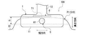
- FIG. 10 is a top view showing a state in which the skin is clamped by the assisting device 100.
- FIG. 11 is a cross-sectional view showing a state in which the nozzle portion 10a of the syringe 200 is received in the receiving portion 5 of the auxiliary tool 100.
- Reference S10 in FIG. 9 indicates the skin of a mammal.
- Reference S1 in FIG. 9 indicates the epidermis
- reference S2 indicates the dermis
- reference S3 indicates the subcutaneous tissue.
- the skin S10 is composed of three layers: epidermis S1, dermis S2, and subcutaneous tissue S3.
- symbol F3 of FIG. 9 shows the surface (henceforth skin surface) of skin S10.
- step S100 the syringe 200 and the auxiliary tool 100 are prepared.
- the skin S10 is pinched by the auxiliary tool 100 as shown in FIG.
- the user operates the auxiliary tool 100 to open it, and pinches the skin S10 between the first pinching piece 11 and the second pinching piece 21, thereby pinching the skin S10.
- the state in which the first clamping piece 11 and the second clamping piece 21 clamp the skin S10 is maintained by the biasing force of the biasing member 4 that attempts to close the assisting device 100 .
- a fold-like portion P1 is formed by protruding the skin S10 in a fold-like shape.
- the skin S1 is deformed so as to be bent into a U shape.
- the symbol T1 in FIG. 9 indicates the most protruding part of the fold P1, that is, the top of the fold P1 (hereinafter referred to as the fold top).
- the crest top T1 is a folded portion of the skin S1.
- the fold root portion B1 is the base end portion of the fold-shaped portion P1. Also, as shown in FIG. 9, the direction in which the folds P1 protrude is the height direction of the folds P1.
- the skin S10 is clamped so that the fold top T1 abuts against the positioning portion 6, thereby positioning the fold top T1.
- the skin surface F3 in the fold apex vicinity region A1 which is the region in the vicinity of the fold apex T1, of the fold P1 is exposed from the receiving portion 5.
- the fold top vicinity region A1 is a region located within the distance d1 from the fold top T1 to the fold base B1 side in the height direction of the fold P1 in the fold P1.
- the injection target substance is injected into the region A1 near the top of the fold.
- the nozzle portion 10a of the syringe 200 is received (inserted) into the receiving portion 5 of the auxiliary tool 100, as shown in FIG.
- the nozzle part 10a is inserted into the receiving part 5 along the direction perpendicular to the first clamping piece 11, that is, along the direction perpendicular to the skin surface F3 in the region A1 near the top of the fold.
- the first extending portion 12 of the first holding member 1 of the auxiliary tool 100 is arranged in the first extending portion 12 such that the first holding piece 11 and the first extending portion 12 form a straight line.
- the second extension portion 22 of the second clamping member 2 extends from the clamping piece 11, and the second clamping piece 21 and the second extension portion 22 form a V shape. extends from In other words, the first extending portion 12 extends so as not to be located on the front side of the first clamping piece 11 in the insertion direction of the nozzle portion 10 a into the receiving portion 5 . Therefore, when the nozzle portion 10 a is received in the receiving portion 5 , the nozzle portion 10 a does not interfere with the first extension portion 12 .
- the receiving part 5 By receiving the nozzle part 10a in the receiving part 5, the receiving part 5 is engaged with the nozzle part 10a, and the ejection port 10b is positioned from the receiving part 5 to the region A1 near the top of the fold where the skin surface F3 is exposed.
- the nozzle part 10a is vertically pressed against the skin surface F3 in the fold top vicinity area A1 of the fold P1, and the injection port 10b faces the fold top vicinity area A1.
- the nozzle part 10a is pressed against the fold top vicinity area A1, and the injection port 10b is brought into contact with the skin surface F3 in the fold top vicinity area A1.
- the user operates the syringe 200 to inject the injection target substance from the injection port 10b into the region A1 near the top of the fold.
- An injection target substance is injected into the skin of A1.
- the region A1 near the top of the fold includes the epidermis S1 and the dermis S2, and the subcutaneous tissue S3. is not included. Therefore, the injection target substance is intensively and reliably injected into the epidermis S1 and the dermis S2.
- the second clamping surface F2 of the second clamping piece 21 located on the opposite side of the nozzle portion 10a across the folds P1 is formed as a flat surface, the folds P1 and the second clamping surface are flat. It is in close contact with F2. Therefore, the fold P1 is stably supported by the second holding surface F2, and the injection target substance is reliably injected into the fold top vicinity area A1.
- the skin S10 forms a fold-like portion P1 in which the skin is raised in a fold-like shape.
- the receiving portion 5 provided in the first clamping piece 11 exposes the crest crest vicinity region A1, which is the region near the crest crest T1, of the crimp P1, and is capable of receiving the nozzle portion 10a of the syringe 200. be.
- the injection target substance is injected into the fold top vicinity region A1.
- substance is ejected.
- the assisting device 100 it is possible to selectively and reliably inject the injection target substance into the epidermis S1 and the dermis S2 in intradermal injection of a mammal using a needle-free syringe.
- a more effective response to a specific injection target substance such as a vaccine or a gene therapy agent
- a specific injection target substance such as a vaccine or a gene therapy agent
- a conventional injection method using a needle-free injector aims at injection into the epidermis or dermis by adjusting the output of the needle-free injector for injecting the injection target substance.
- the thickness of the skin varies depending on the type, site, sex, age (weeks of age), etc. of the animal, it has been difficult to inject the injection target substance selectively and reliably into the epidermis and dermis.
- the assisting device 100 it is possible to inject the target substance into the epidermis S1 and the dermis S2 intensively and reliably, so that the intradermally administered gene can be effectively expressed. can be made As a result, it is possible to effectively realize a response to a specific injection target substance such as a vaccine or a gene therapy agent.
- the receiving portion 5 may expose a region of the fold P1 located within 3 mm from the fold top T1 to the fold base B1 side. That is, d1 may be set to 3 mm, and a region of the fold P1 located within 3 mm from the fold top T1 toward the fold base B1 may be exposed from the receiving portion 5 as the fold top vicinity region A1.
- the injection target substance is injected at a position within 3 mm from the fold top T1 to the fold base B1 side.
- the injection target substance can be more reliably injected into the epidermis S1 and the dermis S2.
- the auxiliary tool 100 is provided on the first clamping surface F1 of the first clamping piece 11, and the positioning part 6 which positions the fold top T1 by coming into contact with the fold top T1 of the fold P1. It has As a result, the pleat crest vicinity region A1 can be reliably exposed from the receiving portion 5 .
- the positioning portion is not an essential component in the technique of the present disclosure.
- the positioning portion may be provided on the holding surface of at least one of the first holding piece and the second holding piece.
- the positioning portion may be provided only on the holding surface of the second holding piece, or may be provided on both the holding surfaces of the first holding piece and the second holding piece.
- the receiving portion 5 of the assisting device 100 is configured to engage with the nozzle portion 10a of the syringe 200 to position the ejection port 10b with respect to the region A1 near the crest portion. According to this, the nozzle part 10a is prevented from being displaced from the fold top vicinity area A1 at the time of injection, and the injection target substance can be more reliably injected into the fold top vicinity area A1.
- FIG. 12 is a top view showing a state in which the nozzle portion of the needle-free syringe is received in the receiving portion of the auxiliary tool according to Embodiment 1.
- FIG. The symbol X in FIG. 12 indicates the distance between the ejection port 10b of the nozzle portion 10a engaged with the receiving portion 5 and the fold top portion T1 in the height direction of the fold portion P1. At this time, X ⁇ 3 mm may be set.
- the receiving portion 5 engages with the nozzle portion 10a of the syringe 200 so that the ejection port 10b is located within 3 mm from the pleat crest T1 toward the pleat root portion B1 of the fold P1. may be positioned.
- the injection target substance can be reliably injected to a position within 3 mm from the fold top T1 to the fold base B1 side. As a result, the injection target substance can be more reliably injected into the epidermis S1 and the dermis S2.
- the receiving portion 5 is engaged with the nozzle portion 10a to position the ejection port 10b so that the ejection port 10b is located within 1.5 mm from the crest of the fold to the root of the fold.
- the injection target substance can be reliably injected to a position within 1.5 mm from the fold top T1 to the fold base B1 side.
- the injection target substance can be more reliably injected into the epidermis S1 and the dermis S2.
- the second holding surface F2 of the second holding piece 21 of the auxiliary tool 100 is formed as a flat surface.
- the folds P1 and the second clamping surface F2 are brought into close contact, the folds P1 are stably supported by the second clamping surfaces F2, and the injection target substance is reliably injected into the region A1 near the top of the folds. can do.
- the first extension portion 12 of the assisting tool 100 is configured so that the nozzle portion 10a does not interfere with the first extension portion 12 when the nozzle portion 10a of the syringe 200 is received in the receiving portion 5. extended. Accordingly, the nozzle portion 10a can be smoothly received in the receiving portion 5. As shown in FIG.
- the luciferase activity was measured using Promega's luciferase assay kit (catalog No. E1500).
- the frozen skin was thawed in 500 ⁇ L of tissue lysing solution and cut to approximately 1.5 mm or less using scissors. It was then freeze-thawed three times. 100 ⁇ L of substrate solution was added to 20 ⁇ L of the supernatant obtained by centrifuging the lysate, and after stirring, the luminescence amount (Relative Light Unit; RLU) was measured using a Kikkoman P-100 device. By doing so, the expression level of the luciferase gene was measured.
- RLU Relative Light Unit
- Example 1 injection was performed by the injection method using the aid according to the first embodiment. Specifically, the skin to be administered was clamped using the aid according to Embodiment 1, and the luciferase-expressing plasmid was injected into the region near the fold top using a needle-free syringe.
- a comparative example administration was performed using a conventional needle-free injector. That is, the luciferase-expressing plasmid was injected by vertically pressing the nozzle portion of a needle-free syringe against the skin to be administered without using the aid according to the present embodiment.
- [Modification 1] 14 is a cross-sectional view of an auxiliary tool 100A according to Modification 1 of Embodiment 1.
- FIG. 14 the assisting tool 100A is different from the assisting tool 100 in that a non-slip portion 7 is provided on the second holding surface F2 of the second holding piece 21.
- the non-slip portion 7 is for suppressing slipping of the fold-shaped portion P1 sandwiched by the first sandwiching piece 11 and the second sandwiching piece 21 .
- the material of the anti-slip portion 7 is not particularly limited, the anti-slip portion 7 can be formed, for example, by coating the second holding surface F2 with silicone resin.
- the assisting tool 100A according to Modification 1 of Embodiment 1, it is possible to prevent the fold P1 from being displaced with respect to the assisting tool 100 during injection. As a result, the fold top vicinity area A1 can be maintained in a state of being exposed from the receiving part 5, and the injection target substance can be more reliably injected into the fold top vicinity area A1.
- the non-slip portion may be provided on the holding surface of at least one of the first holding piece and the second holding piece.
- the anti-slip portion may be provided only on the gripping surface of the first gripping piece, or the gripping surface of both the first gripping piece and the second gripping piece may be provided with the anti-slip portion.
- FIG. 15 is a top view showing a state in which the nozzle portion 10a of the syringe 200 is received in the receiving portion 5B of the auxiliary tool 100B according to Modification 2 of the first embodiment.
- the auxiliary tool 100B differs from the auxiliary tool 100 in that the receiving portion 5B is formed in a slit shape.
- the receiving portion 5B according to Modification 2 is formed as a slit provided in the first holding piece 11 so as to extend along the height direction of the fold-shaped portion P1.
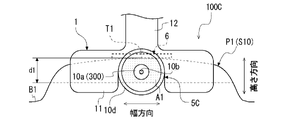
- FIG. 16 is a top view showing a state in which the nozzle portion 10a of the syringe 300 according to the modified example is received in the receiving portion 5C of the auxiliary tool 100C according to the modified example 3 of the first embodiment.
- the assisting tool 100C is different from the assisting tool 100 in that the pressing part 10d is formed so that the receiving part 5C can receive it.
- the pressing portion 10d that can be received by the receiving portion 5C according to Modification 3 surrounds the nozzle portion 10a and has a predetermined gap between itself and the nozzle portion 10a, as disclosed in Japanese Unexamined Patent Application Publication No. 2020-31715. provided to be formed. This makes it easier to form and maintain a suitable contact state between the skin S10, which is the injection target region, and the nozzle portion 10a.
- FIG. 17 is an overall view of an assisting tool 100D according to Embodiment 2.
- FIG. 17 the same reference numerals as those of the assisting tool 100 are assigned to the same configurations as those of the assisting tool 100 according to the first embodiment.
- An auxiliary tool 100D according to the second embodiment is formed by processing a so-called clothespin.
- An auxiliary tool 100D according to the second embodiment includes a first clamping piece 11, a second clamping piece 21, and a receiving portion 5, like the auxiliary tool 100 according to the first embodiment. Therefore, as with the first embodiment, the auxiliary device 100D can also inject the injection target substance selectively and reliably into the epidermis S1 and dermis S2 in intradermal injection of a mammal using a needle-free syringe.
- FIG. 18 is a cross-sectional view of a needle-free syringe 1000 with an assisting device according to Embodiment 3.
- FIG. The needle-free syringe 1000 with an assisting device is obtained by connecting the syringe 200 and the assisting device 100 according to the first embodiment via a connecting means C1.
- the syringe 200 and the auxiliary tool 100 are connected with the nozzle portion 10 a received in the receiving portion 5 .
- the syringe 200 When performing an intradermal injection of a mammal using the needle-free syringe 1000 with an auxiliary tool, the syringe 200 is operated in a state in which the skin S10 is sandwiched by the auxiliary tool 100 to form the fold P1, and the injection is received.
- the injection target substance may be injected from the injection port 10b into the region A1 near the top of the fold exposed from the portion 5 .
- the nozzle portion 10a is received in the receiving portion 5 so that the injection port 10b faces the fold top region A1 of the fold P1. Therefore, the operation of inserting the nozzle portion 10a into the receiving portion 5 after the skin S10 is pinched by the auxiliary tool 100 can be omitted.
- the connecting means C1 is not an essential configuration in the technique of the present disclosure, and it is sufficient that the assisting device and the needle-free syringe are connected while the nozzle portion is received in the receiving portion.
- An injection method for injecting an injection target substance into the skin of a mammal by injecting the injection target substance from an injection port formed in a nozzle portion of a needle-free injector comprising: Preparing the needle-free syringe, an auxiliary tool comprising a first clamping piece and a second clamping piece facing each other, and a receiving portion provided on the first clamping piece and capable of receiving the nozzle portion; The skin is pinched and pinched by the mutually opposing pinching surfaces of the first pinching piece and the second pinching piece to form a fold-shaped portion in which the skin is raised in a fold-like shape, and , exposing a region near the top of the fold, which is the region near the top of the fold, from the receiving portion; receiving the nozzle portion of the needle-free syringe in the receiving portion while holding the skin, and injecting the injection target substance from the injection port into the region near the fold top; injection method.
- ⁇ Appendix 2> In injecting the injection target substance from the injection port, the injection target substance is injected at a position within 3 mm from the fold top to the fold root side in the folds, The injection method according to appendix 1.
- ⁇ Appendix 3> In injecting the injection target substance from the injection port, the injection target substance is injected at a position within 1.5 mm from the fold top to the fold root side in the folds.
- the injection target substance contains a gene, 4.
- Reference Signs List 1 first holding member 2: second holding member 3: connecting member 4: biasing member 5: receiving portion 6: positioning portion 7: anti-slip portion 10a: nozzle portion 10b: injection port 11: first holding piece 12: First extending portion 12a: First gripping portion 21: Second clamping piece 22: Second extending portion 22a: Second gripping portion 100: Auxiliary tool 200: Needle-free syringe 1000: Needle-free syringe with auxiliary tool
Landscapes
- Health & Medical Sciences (AREA)
- Vascular Medicine (AREA)
- Heart & Thoracic Surgery (AREA)
- Engineering & Computer Science (AREA)
- Anesthesiology (AREA)
- Biomedical Technology (AREA)
- Hematology (AREA)
- Life Sciences & Earth Sciences (AREA)
- Animal Behavior & Ethology (AREA)
- General Health & Medical Sciences (AREA)
- Public Health (AREA)
- Veterinary Medicine (AREA)
- Dermatology (AREA)
- Infusion, Injection, And Reservoir Apparatuses (AREA)
Priority Applications (4)
| Application Number | Priority Date | Filing Date | Title |
|---|---|---|---|
| CN202280031899.6A CN117222443A (zh) | 2021-03-01 | 2022-02-28 | 应用于无针注射器的辅助用具、带辅助用具的无针注射器以及对皮内的注射方法 |
| JP2023503831A JPWO2022186145A1 (https=) | 2021-03-01 | 2022-02-28 | |
| US18/279,785 US20240226460A9 (en) | 2021-03-01 | 2022-02-28 | Aid to be applied to needleless syringe, needleless syringe provided with aid, and intradermal injection method |
| EP22763201.5A EP4302807A4 (en) | 2021-03-01 | 2022-02-28 | AID FOR APPLYING TO A NEEDLELESS SYRINGE, NEEDLELESS SYRINGE PROVIDED WITH AID AND INTRADERMAL INJECTION METHOD |
Applications Claiming Priority (2)
| Application Number | Priority Date | Filing Date | Title |
|---|---|---|---|
| JP2021032022 | 2021-03-01 | ||
| JP2021-032022 | 2021-03-01 |
Publications (1)
| Publication Number | Publication Date |
|---|---|
| WO2022186145A1 true WO2022186145A1 (ja) | 2022-09-09 |
Family
ID=83153734
Family Applications (1)
| Application Number | Title | Priority Date | Filing Date |
|---|---|---|---|
| PCT/JP2022/008323 Ceased WO2022186145A1 (ja) | 2021-03-01 | 2022-02-28 | 無針注射器に適用される補助具、補助具付き無針注射器、及び皮内への注射方法 |
Country Status (5)
| Country | Link |
|---|---|
| US (1) | US20240226460A9 (https=) |
| EP (1) | EP4302807A4 (https=) |
| JP (1) | JPWO2022186145A1 (https=) |
| CN (1) | CN117222443A (https=) |
| WO (1) | WO2022186145A1 (https=) |
Cited By (1)
| Publication number | Priority date | Publication date | Assignee | Title |
|---|---|---|---|---|
| EP4529939A1 (de) * | 2023-09-28 | 2025-04-02 | Heraeus Medical GmbH | Vorrichtung zur positionierung eines injektors, injektionsvorrichtung und verfahren |
Citations (11)
| Publication number | Priority date | Publication date | Assignee | Title |
|---|---|---|---|---|
| US5242453A (en) * | 1991-07-01 | 1993-09-07 | Gubich Stephen J | Device for puckering the flesh to facilitate injections |
| US6406456B1 (en) | 2000-06-08 | 2002-06-18 | Avant Drug Delivery Systems, Inc. | Jet injector |
| JP2007061577A (ja) | 2005-09-01 | 2007-03-15 | Eisuke Fujimoto | 無針注射器 |
| JP2007267838A (ja) | 2006-03-30 | 2007-10-18 | Terumo Corp | 無針注射器具 |
| WO2009111794A1 (en) | 2008-03-07 | 2009-09-11 | Pharmajet, Inc. | Intradermal injector and uses thereof |
| WO2012036264A1 (ja) | 2010-09-17 | 2012-03-22 | ダイセル化学工業株式会社 | 注射器 |
| JP2015506211A (ja) * | 2012-01-10 | 2015-03-02 | サノフィ−アベンティス・ドイチュラント・ゲゼルシャフト・ミット・ベシュレンクテル・ハフツング | 皮内注射用の案内アセンブリ |
| WO2019004322A1 (ja) | 2017-06-27 | 2019-01-03 | 株式会社ダイセル | 無針注射器、無針注射器による終了時到達深さの調整方法、および無針注射器の射出パラメータ算出プログラム |
| WO2020027325A1 (ja) * | 2018-08-03 | 2020-02-06 | 株式会社ダイセル | 無針注射器 |
| JP2020031715A (ja) | 2018-08-27 | 2020-03-05 | 株式会社ダイセル | 無針注射器 |
| JP2021500210A (ja) * | 2017-10-26 | 2021-01-07 | エヌディーエム テクノロジーズ リミテッド | 注射装置 |
Family Cites Families (9)
| Publication number | Priority date | Publication date | Assignee | Title |
|---|---|---|---|---|
| JP5249204B2 (ja) * | 2007-04-27 | 2013-07-31 | テルモ株式会社 | 穿刺器具 |
| JP2008295590A (ja) * | 2007-05-29 | 2008-12-11 | Terumo Corp | 穿刺器具 |
| JP5218067B2 (ja) * | 2009-01-05 | 2013-06-26 | ニプロ株式会社 | 穿刺補助器具 |
| EP2435116B1 (en) * | 2009-05-28 | 2020-07-01 | Simcro Limited | Skin gripping means, injector including the skin gripping means for performing a subcutaneous injection |
| US9089655B2 (en) * | 2009-07-23 | 2015-07-28 | Sid Technologies, Llc | Intradermal injection adapter |
| EP3100756A4 (en) * | 2014-01-31 | 2017-10-11 | Terumo Kabushiki Kaisha | Puncture aid and puncture instrument set |
| GB2544499A (en) * | 2015-11-18 | 2017-05-24 | Tickletec Ltd | Injector pen safety aid |
| CN205515031U (zh) * | 2016-02-02 | 2016-08-31 | 冷水龙 | 一种动物皮下注射的辅助装置 |
| CN210330819U (zh) * | 2019-05-31 | 2020-04-17 | 广西壮族自治区畜牧研究所 | 动物皮内注射装置及其注射辅助器 |
-
2022
- 2022-02-28 JP JP2023503831A patent/JPWO2022186145A1/ja active Pending
- 2022-02-28 US US18/279,785 patent/US20240226460A9/en active Pending
- 2022-02-28 CN CN202280031899.6A patent/CN117222443A/zh active Pending
- 2022-02-28 EP EP22763201.5A patent/EP4302807A4/en active Pending
- 2022-02-28 WO PCT/JP2022/008323 patent/WO2022186145A1/ja not_active Ceased
Patent Citations (11)
| Publication number | Priority date | Publication date | Assignee | Title |
|---|---|---|---|---|
| US5242453A (en) * | 1991-07-01 | 1993-09-07 | Gubich Stephen J | Device for puckering the flesh to facilitate injections |
| US6406456B1 (en) | 2000-06-08 | 2002-06-18 | Avant Drug Delivery Systems, Inc. | Jet injector |
| JP2007061577A (ja) | 2005-09-01 | 2007-03-15 | Eisuke Fujimoto | 無針注射器 |
| JP2007267838A (ja) | 2006-03-30 | 2007-10-18 | Terumo Corp | 無針注射器具 |
| WO2009111794A1 (en) | 2008-03-07 | 2009-09-11 | Pharmajet, Inc. | Intradermal injector and uses thereof |
| WO2012036264A1 (ja) | 2010-09-17 | 2012-03-22 | ダイセル化学工業株式会社 | 注射器 |
| JP2015506211A (ja) * | 2012-01-10 | 2015-03-02 | サノフィ−アベンティス・ドイチュラント・ゲゼルシャフト・ミット・ベシュレンクテル・ハフツング | 皮内注射用の案内アセンブリ |
| WO2019004322A1 (ja) | 2017-06-27 | 2019-01-03 | 株式会社ダイセル | 無針注射器、無針注射器による終了時到達深さの調整方法、および無針注射器の射出パラメータ算出プログラム |
| JP2021500210A (ja) * | 2017-10-26 | 2021-01-07 | エヌディーエム テクノロジーズ リミテッド | 注射装置 |
| WO2020027325A1 (ja) * | 2018-08-03 | 2020-02-06 | 株式会社ダイセル | 無針注射器 |
| JP2020031715A (ja) | 2018-08-27 | 2020-03-05 | 株式会社ダイセル | 無針注射器 |
Non-Patent Citations (1)
| Title |
|---|
| See also references of EP4302807A4 |
Cited By (2)
| Publication number | Priority date | Publication date | Assignee | Title |
|---|---|---|---|---|
| EP4529939A1 (de) * | 2023-09-28 | 2025-04-02 | Heraeus Medical GmbH | Vorrichtung zur positionierung eines injektors, injektionsvorrichtung und verfahren |
| AU2024219975B2 (en) * | 2023-09-28 | 2026-03-05 | Heraeus Medical Gmbh | Device for positioning an injector, injection device and method |
Also Published As
| Publication number | Publication date |
|---|---|
| JPWO2022186145A1 (https=) | 2022-09-09 |
| EP4302807A4 (en) | 2024-09-04 |
| EP4302807A1 (en) | 2024-01-10 |
| US20240226460A9 (en) | 2024-07-11 |
| US20240131278A1 (en) | 2024-04-25 |
| CN117222443A (zh) | 2023-12-12 |
Similar Documents
| Publication | Publication Date | Title |
|---|---|---|
| US20230329973A1 (en) | Intradermal injection device | |
| US7699802B2 (en) | Needle-less injector | |
| US6406456B1 (en) | Jet injector | |
| US7618393B2 (en) | Needle-less injector and method of fluid delivery | |
| US20180272120A1 (en) | Apparatus for electrically mediated delivery of therapeutic agents | |
| JP6317676B2 (ja) | 無針皮内注射装置 | |
| CN110913931B (zh) | 带有缩回功能的化学驱动的自动注射器 | |
| CA2558735A1 (en) | Intradermal syringe and needle assembly | |
| JP5608498B2 (ja) | 注射器 | |
| JP2015500131A5 (https=) | ||
| CN107921215B (zh) | 无针注射器 | |
| WO2022186145A1 (ja) | 無針注射器に適用される補助具、補助具付き無針注射器、及び皮内への注射方法 | |
| JP6954521B2 (ja) | 射出装置 | |
| MX2023005067A (es) | Ensamblaje de dispositivo de administracion de farmacos y accesorio para dispositivo de administracion de farmacos. | |
| JP7119121B2 (ja) | 無針注射器 | |
| US11975177B2 (en) | Subconjunctival injector and method | |
| DE60134428D1 (de) | Arzneiverabreichungssystem mit halter und arzneimittelbehälter | |
| JP7853225B2 (ja) | 注入器 | |
| WO2019004323A1 (ja) | 注入器 | |
| WO2024057929A1 (ja) | 注入器及び該注入器を用いて溶液を注入する方法 | |
| WO2025105251A1 (ja) | 注入器、及び該注入器を用いて対象に溶液を注入する方法 | |
| CN121419804A (zh) | 防错位件和无针注射器 |
Legal Events
| Date | Code | Title | Description |
|---|---|---|---|
| 121 | Ep: the epo has been informed by wipo that ep was designated in this application |
Ref document number: 22763201 Country of ref document: EP Kind code of ref document: A1 |
|
| WWE | Wipo information: entry into national phase |
Ref document number: 2023503831 Country of ref document: JP |
|
| WWE | Wipo information: entry into national phase |
Ref document number: 18279785 Country of ref document: US |
|
| WWE | Wipo information: entry into national phase |
Ref document number: 2022763201 Country of ref document: EP |
|
| NENP | Non-entry into the national phase |
Ref country code: DE |
|
| ENP | Entry into the national phase |
Ref document number: 2022763201 Country of ref document: EP Effective date: 20231002 |
|
| WWE | Wipo information: entry into national phase |
Ref document number: 202280031899.6 Country of ref document: CN |