WO2022185454A1 - 成分測定装置および成分測定方法 - Google Patents
成分測定装置および成分測定方法 Download PDFInfo
- Publication number
- WO2022185454A1 WO2022185454A1 PCT/JP2021/008216 JP2021008216W WO2022185454A1 WO 2022185454 A1 WO2022185454 A1 WO 2022185454A1 JP 2021008216 W JP2021008216 W JP 2021008216W WO 2022185454 A1 WO2022185454 A1 WO 2022185454A1
- Authority
- WO
- WIPO (PCT)
- Prior art keywords
- excitation light
- stratum corneum
- intensity
- optical medium
- emitted
- Prior art date
- Legal status (The legal status is an assumption and is not a legal conclusion. Google has not performed a legal analysis and makes no representation as to the accuracy of the status listed.)
- Ceased
Links
Images


Classifications
-
- G—PHYSICS
- G01—MEASURING; TESTING
- G01N—INVESTIGATING OR ANALYSING MATERIALS BY DETERMINING THEIR CHEMICAL OR PHYSICAL PROPERTIES
- G01N21/00—Investigating or analysing materials by the use of optical means, i.e. using sub-millimetre waves, infrared, visible or ultraviolet light
- G01N21/17—Systems in which incident light is modified in accordance with the properties of the material investigated
- G01N21/171—Systems in which incident light is modified in accordance with the properties of the material investigated with calorimetric detection, e.g. with thermal lens detection
-
- A—HUMAN NECESSITIES
- A61—MEDICAL OR VETERINARY SCIENCE; HYGIENE
- A61B—DIAGNOSIS; SURGERY; IDENTIFICATION
- A61B5/00—Measuring for diagnostic purposes; Identification of persons
- A61B5/103—Measuring devices for testing the shape, pattern, colour, size or movement of the body or parts thereof, for diagnostic purposes
- A61B5/107—Measuring physical dimensions, e.g. size of the entire body or parts thereof
- A61B5/1075—Measuring physical dimensions, e.g. size of the entire body or parts thereof for measuring dimensions by non-invasive methods, e.g. for determining thickness of tissue layer
-
- A—HUMAN NECESSITIES
- A61—MEDICAL OR VETERINARY SCIENCE; HYGIENE
- A61B—DIAGNOSIS; SURGERY; IDENTIFICATION
- A61B5/00—Measuring for diagnostic purposes; Identification of persons
- A61B5/145—Measuring characteristics of blood in vivo, e.g. gas concentration or pH-value ; Measuring characteristics of body fluids or tissues, e.g. interstitial fluid or cerebral tissue
- A61B5/14532—Measuring characteristics of blood in vivo, e.g. gas concentration or pH-value ; Measuring characteristics of body fluids or tissues, e.g. interstitial fluid or cerebral tissue for measuring glucose, e.g. by tissue impedance measurement
-
- A—HUMAN NECESSITIES
- A61—MEDICAL OR VETERINARY SCIENCE; HYGIENE
- A61B—DIAGNOSIS; SURGERY; IDENTIFICATION
- A61B5/00—Measuring for diagnostic purposes; Identification of persons
- A61B5/145—Measuring characteristics of blood in vivo, e.g. gas concentration or pH-value ; Measuring characteristics of body fluids or tissues, e.g. interstitial fluid or cerebral tissue
- A61B5/1455—Measuring characteristics of blood in vivo, e.g. gas concentration or pH-value ; Measuring characteristics of body fluids or tissues, e.g. interstitial fluid or cerebral tissue using optical sensors, e.g. spectral photometrical oximeters
-
- A—HUMAN NECESSITIES
- A61—MEDICAL OR VETERINARY SCIENCE; HYGIENE
- A61B—DIAGNOSIS; SURGERY; IDENTIFICATION
- A61B5/00—Measuring for diagnostic purposes; Identification of persons
- A61B5/68—Arrangements of detecting, measuring or recording means, e.g. sensors, in relation to patient
- A61B5/6801—Arrangements of detecting, measuring or recording means, e.g. sensors, in relation to patient specially adapted to be attached to or worn on the body surface
- A61B5/6813—Specially adapted to be attached to a specific body part
- A61B5/6825—Hand
- A61B5/6826—Finger
-
- G—PHYSICS
- G01—MEASURING; TESTING
- G01N—INVESTIGATING OR ANALYSING MATERIALS BY DETERMINING THEIR CHEMICAL OR PHYSICAL PROPERTIES
- G01N21/00—Investigating or analysing materials by the use of optical means, i.e. using sub-millimetre waves, infrared, visible or ultraviolet light
- G01N21/17—Systems in which incident light is modified in accordance with the properties of the material investigated
- G01N21/1717—Systems in which incident light is modified in accordance with the properties of the material investigated with a modulation of one or more physical properties of the sample during the optical investigation, e.g. electro-reflectance
-
- A—HUMAN NECESSITIES
- A61—MEDICAL OR VETERINARY SCIENCE; HYGIENE
- A61B—DIAGNOSIS; SURGERY; IDENTIFICATION
- A61B2562/00—Details of sensors; Constructional details of sensor housings or probes; Accessories for sensors
- A61B2562/02—Details of sensors specially adapted for in-vivo measurements
- A61B2562/0233—Special features of optical sensors or probes classified in A61B5/00
- A61B2562/0238—Optical sensor arrangements for performing transmission measurements on body tissue
-
- A—HUMAN NECESSITIES
- A61—MEDICAL OR VETERINARY SCIENCE; HYGIENE
- A61B—DIAGNOSIS; SURGERY; IDENTIFICATION
- A61B2562/00—Details of sensors; Constructional details of sensor housings or probes; Accessories for sensors
- A61B2562/14—Coupling media or elements to improve sensor contact with skin or tissue
- A61B2562/146—Coupling media or elements to improve sensor contact with skin or tissue for optical coupling
-
- G—PHYSICS
- G01—MEASURING; TESTING
- G01N—INVESTIGATING OR ANALYSING MATERIALS BY DETERMINING THEIR CHEMICAL OR PHYSICAL PROPERTIES
- G01N21/00—Investigating or analysing materials by the use of optical means, i.e. using sub-millimetre waves, infrared, visible or ultraviolet light
- G01N21/17—Systems in which incident light is modified in accordance with the properties of the material investigated
- G01N21/1717—Systems in which incident light is modified in accordance with the properties of the material investigated with a modulation of one or more physical properties of the sample during the optical investigation, e.g. electro-reflectance
- G01N2021/1725—Modulation of properties by light, e.g. photoreflectance
-
- G—PHYSICS
- G01—MEASURING; TESTING
- G01N—INVESTIGATING OR ANALYSING MATERIALS BY DETERMINING THEIR CHEMICAL OR PHYSICAL PROPERTIES
- G01N21/00—Investigating or analysing materials by the use of optical means, i.e. using sub-millimetre waves, infrared, visible or ultraviolet light
- G01N21/17—Systems in which incident light is modified in accordance with the properties of the material investigated
- G01N21/25—Colour; Spectral properties, i.e. comparison of effect of material on the light at two or more different wavelengths or wavelength bands
- G01N21/31—Investigating relative effect of material at wavelengths characteristic of specific elements or molecules, e.g. atomic absorption spectrometry
- G01N21/314—Investigating relative effect of material at wavelengths characteristic of specific elements or molecules, e.g. atomic absorption spectrometry with comparison of measurements at specific and non-specific wavelengths
Definitions
- the present invention relates to a component measuring device and a component measuring method, and more specifically to a component measuring device and a component measuring method for measuring components in a living body.
- component measurement devices are known that measure components contained in samples.
- a component measuring device for measuring components contained in a living body is known.
- Most of the component measuring devices adopt an invasive method based on chemical analysis.
- measurement involves partial separation of substances or changes due to chemical reactions.
- an invasive sensor that collects blood using a needle and reacts the reagent with the blood is widely used.
- Invasive component measurement devices cause pain to the patient due to puncture, for example, when measuring blood sugar levels. Therefore, especially in the fields of medicine and healthcare, there has been a demand for a non-invasive component measuring device.
- non-invasive component measurement devices use photothermal spectroscopy to perform measurements based on interstitial fluid, in which biological components are propagated from blood.
- the non-invasive component measuring device of Patent Document 1 when measuring components such as blood sugar levels and lipids in biological measurements, measurements are performed based on interstitial fluid in which biological components are propagated from blood.
- Interstitial fluid is liquid contained in cells and is present even in regions closer to the surface of the skin than blood vessels, so it is also preferable for measurement from the outside of the living body.
- the stratum corneum the outermost surface of the skin, is a layer of dead cells.
- the interstitial fluid is not contained in the outermost stratum corneum of the skin, which is a layer of dead cells, but exists in the stratum granulosum below the stratum corneum and deeper.
- the thickness of the stratum corneum is generally determined by the part of the living body, and may differ in parts such as arms, wrists, forehead, abdomen, and parts such as fingers, palms, and soles that come into frequent contact with external substances. Therefore, in the case of the above-described non-invasive component measuring device configured to use interstitial fluid for measurement, there is a possibility that the measurement is performed based on information from a portion that does not contain interstitial fluid. . Therefore, in the non-invasive component measuring apparatus as described above, improvement in component measurement accuracy is required.
- the present invention has been made to solve the above problems, and aims to provide a non-invasive component measuring device and a component measuring method with improved component measurement accuracy.
- a component measuring device is a component measuring device for measuring a target component contained in a sample, comprising: an optical medium section on which the sample is placed; and an excitation light source that emits excitation light to the optical medium section. Then, based on the probe light source that emits probe light to the optical medium portion and the stratum corneum information about the stratum corneum of the sample, intensity modulation is performed on the excitation light emitted by the excitation light source to generate intensity-modulated excitation light.
- An intensity modulating portion that emits intensity-modulated excitation light to an optical medium portion, a probe light emitted from the optical medium portion in the first state from which the excitation light is emitted, and an optical medium in the second state from which the intensity-modulated excitation light is emitted a measurement unit that measures the target component based on the difference from the probe light emitted from the unit.
- a component measuring method is a component measuring method for measuring a target component contained in a sample, and comprises a standing step of placing the sample in an optical medium portion, and exciting excitation light in the optical medium portion. a step of emitting excitation light emitted from a light source; a step of emitting probe light from the probe light source to an optical medium portion; a step of obtaining stratum corneum information about the stratum corneum of the sample; an intensity modulation step of performing intensity modulation on the excitation light emitted by the excitation light source based on the stratum corneum information acquired in the step to generate intensity-modulated excitation light, and emitting the generated intensity-modulated excitation light to the optical medium;
- the target component is measured based on the difference between the probe light emitted from the optical medium portion in the first state from which the light was emitted and the probe light emitted from the optical medium portion in the second state from which the intensity-modulated excitation light was emitted. and a measuring step.
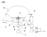
- FIG. 1 is a diagram showing the configuration of a component measuring device according to Embodiment 1.
- FIG. 2 is a top view of an optical medium portion of the component measuring device according to Embodiment 1.
- FIG. 4 is a diagram showing the relationship between the modulation frequency used for measurement and the diffusion length of heat generated inside the skin.
- FIG. 10 is a diagram showing the configuration of a component measuring device according to Embodiment 2;
- component measuring device that measures the blood sugar level in a living body as a component contained in a sample will be described below with reference to the drawings.
- the component measuring device of the present invention can be applied to measure components other than the blood sugar level.
- FIG. 1 is a diagram showing the configuration of a component measuring device 100 according to Embodiment 1.
- the component measuring device 100 according to Embodiment 1 includes an excitation light source 1, a probe light source 2, an optical medium section 3, an optical position detector 4, an optical chopper 9, a lock-in amplifier 10, a stratum corneum information acquisition section 11, and a calculation section. 20.
- the excitation light source 1 includes at least one or more infrared light sources.
- the excitation light source 1 excites infrared light in the entire wavelength range of 8 ⁇ m to 10 ⁇ m including the wavelength of the fingerprint spectrum that can specify the sugar of the blood sugar level to be measured this time, or in a part of the wavelength range.
- the excitation light source 1 includes, as wavelengths used for measurement, wavelengths ⁇ 1 and ⁇ 2 that are absorbed by sugar in the human body, and a wavelength ⁇ 3 that is not absorbed by sugar in the human body and is used as a reference wavelength. Configured.
- the excitation light source 1 may be configured so that four or more wavelengths are used for measurement.
- the probe light source 2 is a laser that outputs, as probe light 7, light in a wavelength range that passes through an optical medium portion 3, which will be described later.
- the probe light source 2 is preferably configured as a laser that outputs light having a wavelength in the visible to near-infrared wavelength region. This is because light with a wavelength in the visible to near-infrared wavelength region is easy to generate and detect as output light, and can reduce the assembly load of the component measuring device 100 .
- the optical medium part 3 is a sample stand on which the sample 5 containing sugar of the blood sugar level to be measured is placed.
- a finger is placed still as the sample 5 on the optical medium section 3 which is the sample table.
- the optical medium section 3 uses, as an optical medium, a substance such as zinc sulfide (ZnS), zinc selenide (ZnSe), germanium (Ge), silicon (Si), chalcogenide glass, or the like, which is highly transmissive in the wavelength region of infrared light. , and is configured to have a predetermined refractive index gradient 8 .
- the refractive index gradient 8 is changed by the excitation light 6 emitted by the excitation light source 1 .
- the optical position detector 4 is a light detection sensor that detects light from the probe light source 2 emitted from the optical medium section 3 .
- the optical position detector 4 detects the path through the optical medium portion 3 of the light emitted from the probe light source 2 by this detection.
- the optical position detector 4 is configured to be able to detect an emitted probe light 7a and an emitted probe refracted light 7b, which will be described later.
- the optical position detector 4 detects the position of light incident on the optical position detector 4 .
- the optical position detector 4 is constructed using, for example, a four-part split photodiode.
- the optical chopper 9 is a component that modulates the intensity of passing light with a specific frequency component.
- the optical chopper 9 is arranged between the excitation light source 1 and the optical medium section 3, performs intensity modulation on the excitation light 6 emitted from the excitation light source 1, and transmits the intensity-modulated excitation light 6' to the optical medium section. It is configured to send to 3.
- the optical chopper 9 has a rotating blade, and by periodically interrupting the continuous excitation light 6 by rotating the rotating blade, the excitation light 6 is subjected to intensity modulation.
- the refractive index gradient 8 of the optical medium portion 3 when irradiated with the excitation light 6 whose intensity is not modulated is different from the refractive index gradient 8 of the optical medium portion 3 when irradiated with the excitation light 6′ whose intensity is modulated. different.
- the optical position detector 4 detects the path of the emitted probe light 7a when irradiated with the excitation light 6 whose intensity is not modulated and the path of the emitted probe refracted light 7b when irradiated with the excitation light 6' whose intensity is modulated. detect differences in
- a lock-in amplifier 10 is connected to the optical position detector 4 and the optical chopper 9 .
- a lock-in amplifier 10 reads a signal synchronized with the modulated frequency component of the excitation light 6 among the signals measured by the optical position detector 4 . Therefore, the component measuring device 100 can perform highly accurate measurement.
- the measurement signal contains noise containing various frequency components, and the lower the frequency, the greater the amount of noise.
- the desired measurement signal is a modulated signal having the same frequency and phase as the modulated excitation light but a different amplitude.
- the measurement signal contains noise containing a large amount of different frequency components, a measurement signal corresponding to the modulation frequency of the excitation light and the frequency of the noise is added.
- the desired component is contained only in the DC component. Therefore, by measuring only the direct-current component using a low-pass filter, noise components can be removed even in minute signals, enabling highly accurate measurement.
- the stratum corneum information acquisition unit 11 is a component that acquires stratum corneum information about the stratum corneum of the sample 5 placed in the optical medium unit 3 .
- the stratum corneum information acquisition unit 11 is an input device that acquires stratum corneum information input by the user of the component measuring device 100 .
- the thickness of the stratum corneum can vary in accuracy due to differences in measurement methods or individual differences, but can generally be determined according to the part of the body. It is known that the thickness is about 20 ⁇ m in parts such as arms, wrists, forehead, and abdomen, while it is formed as thick as 100 to 300 ⁇ m in areas such as fingers, palms, and feet, and parts that come into frequent contact with external substances. ing. Therefore, the stratum corneum information acquisition unit 11 according to Embodiment 1 is a numeric input device such as a numeric keypad, and acquires a thickness value such as 20 ⁇ m from the user as stratum corneum information.
- the input device may be an input device that can select the target part corresponding to the sample 5 from parts such as the arm, wrist, forehead, abdomen, fingers, palm, and foot.
- the thickness values of the stratum corneum corresponding to each part such as the arm, wrist, forehead, abdomen, fingers, palm, and sole are stored in the storage unit, and one selected using the stratum corneum information acquisition unit 11 is obtained. It may be configured so that the thickness value corresponding to the part can be acquired. By using this configuration, it is possible to increase the design flexibility of the component measuring device 100 .
- the calculation unit 20 is a component that calculates the blood sugar level in order to measure the sugar contained in the sample 5.
- the arithmetic section 20 is connected to the lock-in amplifier 10 .
- the calculator 20 calculates the blood sugar level based on the signal acquired by the lock-in amplifier 10 .
- the calculation unit 20 is also a component for adjusting the stratum corneum of the sample 5 .
- the calculation unit 20 is connected to the stratum corneum information acquisition unit 11 in addition to the lock-in amplifier 10 .
- the calculation unit 20 performs intensity modulation on the excitation light 6 emitted from the excitation light source 1 based on the stratum corneum information acquired by the stratum corneum information acquisition unit 11 .
- the calculation unit 20 controls the rotation speed of the optical chopper 9 and sets a modulation frequency, which will be described later.
- the modulation frequency means the frequency in the intensity modulation of the excitation light.
- the component measuring apparatus 100 is arranged such that the probe light 7 from the probe light source 2 enters the optical medium section 3 as incident probe light and is emitted to the optical position detector 4 as outgoing probe light 7a. are placed in
- the excitation light source 1 irradiates the excitation light 6 toward the optical medium portion 3 and absorption heat is generated in the sample 5
- the generated absorption heat propagates to the optical medium portion 3 and causes a temperature gradient in the optical medium portion 3. is formed, and the refractive index gradient 8 of the optical medium portion 3 changes.
- the refractive index of the optical medium portion 3 also changes due to the changed refractive index gradient 8.
- the probe light 7 is emitted to the optical position detector 4 as emitted probe refracted light 7b that follows the .
- the component measuring device 100 detects the deviation between the emitted probe light 7a and the emitted probe refracted light 7b with the optical position detector 4, and performs calculation on the detection result with the calculation unit 20 via the lock-in amplifier 10 to obtain the component It is configured to take measurements.
- the optical position detector 4, the lock-in amplifier 10, the arithmetic unit 20, and the combination thereof described above combine the emitted probe light 7a emitted from the optical medium portion 3 from which the excitation light 6 is emitted and the intensity-modulated excitation light 7a.
- the present invention relates to an example of a measurement unit that measures a target component based on the difference from the emitted probe refracted light 7b emitted from the optical medium portion 3 to which the light 6' is emitted.
- the optical chopper 9 performs intensity modulation based on the modulation frequency set by the calculation unit 20 so that the excitation light 6 emitted from the excitation light source 1 has a modulation frequency corresponding to the stratum corneum information acquired by the stratum corneum information acquisition unit 11. I do.
- the excitation light 6 is intensity-modulated by rotating the rotary blade at a rotation speed corresponding to the modulation frequency set by the calculation unit 20 . That is, the optical chopper 9 corresponds to an example of the intensity modulating section according to the invention.
- the excitation light 6 ′ intensity-modulated after passing through the optical chopper 9 passes through the optical medium portion 3 and enters the sample 5 .
- the sample 5 corresponds to a subject's finger, wrist, arm, earlobe, or other site.
- the calculation unit 20 calculates the absorption of sugar components contained in the interstitial fluid of the sample 5 on which the probe light 7 is incident from the skin.
- FIG. 2 is a top view of the optical medium part 3 of the component measuring device 100 according to Embodiment 1.
- the excitation light source 1 and the probe light source 2 are configured so that the optical path of the probe light 7 intersects the excitation light 6 from the excitation light source 1 at the excitation light irradiation site in plan view of FIG.
- the beam width of the excitation light 6 emitted by the excitation light source 1 is approximately the same as the beam width of the probe light 7 emitted by the probe light source 2. It is preferable that it is above.
- the refractive index gradient generating region ⁇ will become smaller than the beam width of the probe light 7 . If the refractive index gradient generating region ⁇ is smaller than the beam width of the probe light 7, only a part of the probe light is affected, making it difficult to measure changes in the optical path of the probe light 7. FIG. On the other hand, if the beam width of the excitation light is too large, the density of the excitation light may decrease, or the refractive index gradient generation region ⁇ may expand. If the density of the excitation light becomes unnecessarily low, or if the refractive index gradient generating region ⁇ expands unnecessarily, the refractive index gradient itself may become small.
- the beam width of the excitation light is set to 50 ⁇ m and the beam width of the probe light to 30 ⁇ m.
- the operation of blood sugar level measurement in the component measuring device 100 will be described.
- An example in which the light output of the excitation light source 1 is zero will be described as a reference state.
- the reference state the internal state of the optical medium portion 3 is considered uniform. Therefore, the probe light 7 output from the probe light source 2 is refracted only when it enters the optical medium portion 3 and when it leaves the optical medium portion 3 .
- the position at which the emitted probe light 7a is incident on the optical position detector 4 in the reference state is defined as the reference position.
- the probe light 7 is totally reflected once by the contact surface with the sample 5 at the excitation light irradiation site.
- a refractive index gradient 8 generated in the optical medium which will be described later, is generated near the surface of the optical medium portion 3, and the gradient increases as it approaches the surface in contact with the area where heat is generated.
- the probe light source By arranging the probe light source as described above, it becomes possible to make the incident angle of the probe light 7 shallow, and the probe light 7 becomes a path through which the probe light 7 passes near the surface of the optical medium. Therefore, the optical path can be changed efficiently.
- the probe light 7 is refracted by passing through the refractive index gradient 8, and the optical path is changed. Therefore, for example, it may be configured such that the path is totally reflected twice or more in the optical medium portion 3, or it may be configured as a path that passes through the vicinity of the contact surface with the sample 5 in parallel with the contact surface. good.
- the excitation light source 1 emits infrared light of sugar fingerprint spectrum wavelength as the excitation light 6 .
- the optical chopper 9 modulates the intensity of the excitation light 6 output from the excitation light source 1 .
- the excitation light 6 intensity-modulated by the optical chopper 9 passes through the optical medium portion 3 and enters the sample 5 .
- the excitation light 6 which is infrared light incident on the sample 5 is absorbed by sugar contained in the interstitial fluid existing near the surface of the sample 5 . Heat of absorption is generated inside the sample 5 when the excitation light 6 is absorbed by the sugar. The generated absorption heat propagates from the sample 5 to the optical medium portion 3 .
- the refractive index of the optical medium portion 3 generally has temperature dependence. Therefore, when a temperature gradient occurs in the optical medium portion 3, a refractive index gradient 8 is formed in which the refractive index has a gradient.
- state A The state in which the refractive index gradient 8 is formed is referred to as state A, and the following description will be given.
- the thermal diffusion length L which is the length in which the generated heat diffuses, is the modulation of the excitation light 6.
- the frequency f at which the heat of absorption corresponding to the frequency is generated and the thermal diffusion coefficient ⁇ of the sample 5 it is expressed by the following equation (1).
- the thermal diffusion coefficient of the skin of this part is about 0.13 to 0.17 mm 2 /s. ... formula (1)
- FIG. 3 is a diagram showing the relationship between the modulation frequency used for measurement and the diffusion length of heat generated inside the skin.
- FIG. 3 shows the thermal diffusion length inside the skin versus the modulation frequency when the thermal diffusion coefficient is 0.15 mm 2 /s.
- the modulation frequency is about 20 ⁇ m at 100 Hz, about 40 ⁇ m at 30 Hz, and about 100 ⁇ m at 5 Hz.
- the modulation frequency f is set as f ⁇ /(d 2 ⁇ ).
- the thermal diffusion length is in the range of 1 to 3 times the thickness of the stratum corneum, and ⁇ / ⁇ (3d) 2 ⁇ f ⁇ /(d 2 ⁇ ) is set. .
- the modulation frequency it is necessary to lower the modulation frequency, but the noise generated during measurement usually increases in the lower frequency region. Therefore, if the modulation frequency is low, the S/N ratio of the signal may decrease even if a lock-in amplifier is used. Therefore, the frequency used is preferably as high as possible within the range where interstitial fluid can be measured.
- the calculation unit 20 when measuring a finger or palm with a thick stratum corneum of 100 ⁇ m or more, the calculation unit 20 modulates the excitation light 6 via the lock-in amplifier 10 so that the modulation frequency is 0.5 to 5 Hz. Set the rotation speed of the chopper 9. Similarly, when measuring a part such as the arm, wrist, or forehead, where the stratum corneum is about 20 ⁇ m, the calculation unit 20 sets the modulation frequency of the excitation light 6 to 15 to 100 Hz through the lock-in amplifier 10. set as By using the configuration described above, it is possible to measure using higher modulation frequencies when the stratum corneum is relatively thin.
- the probe light 7 is transmitted through the refractive index gradient 8 in which no refractive index gradient occurs, the probe light 7 is refracted according to the refractive index at the position in the optical medium portion 3 where it is transmitted.
- the refracted probe light 7 is emitted from the optical medium section 3 as emitted probe light 7 a and enters the optical position detector 4 .
- the optical position detector detects the position at which the emitted probe light 7a is incident on the optical position detector 4 as a reference position.
- the probe light 7 when the probe light 7 is transmitted through the refractive index gradient 8 in which the refractive index gradient is generated, the probe light 7 has a refractive index within the refractive index gradient 8 at the position where the probe light 7 is transmitted in the optical medium portion 3. refracts according to The refracted incident probe light 7 is emitted from the optical medium section 3 as emitted probe refracted light 7 b and enters the optical position detector 4 .
- the optical position detector detects the position at which the output probe refracted light 7b is incident on the optical position detector 4 as a displacement position.
- the lock-in amplifier 10 reads the signal value based on the difference between the reference position detected by the optical position detector 4 and the displacement position.
- the calculation unit 20 acquires the signal regarding the difference read by the lock-in amplifier 10 and calculates the blood sugar level as a component.
- the component measuring device 100 drives the optical chopper 9 based on the stratum corneum information acquired by the stratum corneum information acquiring unit 11, thereby controlling It is possible to efficiently measure the heat of absorption generated by the target component in the quality liquid.
- the diffusion length of the heat generated inside the living body in the measurement is about 1 to 3 times the thickness of the stratum corneum, and the absorption heat generated by the sugar component in the interstitial fluid contained in the deeper layer than the stratum corneum. can be measured efficiently.
- a component measuring method for measuring the blood sugar level which is the target component contained in the sample 5, will be described using the component measuring device 100 according to the first embodiment.
- a standing step of placing the sample 5 in the optical medium section 3 is executed.
- the excitation light emitting step of emitting the excitation light 6 from the excitation light source 1 to the optical medium portion 3 is performed in the method for measuring this component.
- the method of measuring this component also performs a probe light emitting step of emitting the probe light 7 from the probe light source 2 to the optical medium portion 3 .
- a stratum corneum information obtaining step of obtaining stratum corneum information about the stratum corneum of the sample 5 is also executed.
- excitation light 6 emitted by excitation light source 1 is intensity-modulated to perform intensity-modulated excitation.
- An intensity modulation step of generating light and emitting the generated intensity-modulated excitation light to the optical medium portion 3 is performed.
- the emitted probe light 7a emitted from the optical medium portion 3 from which the excitation light 6 was emitted and the emitted probe light 7a emitted from the optical medium portion 3 from which the intensity-modulated excitation light was emitted A measurement step is executed to measure the blood glucose level, which is the target component, based on the difference from the outgoing probe refracted light 7b.
- the component measurement method according to Embodiment 1 drives the optical chopper 9 based on the stratum corneum information acquired by the stratum corneum information acquisition unit 11 to perform the intensity modulation step, thereby reducing the intensity of the stratum corneum. It is possible to efficiently measure the heat of absorption generated by the target component in the interstitial fluid contained in the deep layer. Specifically, the diffusion length of the heat generated inside the living body in the measurement is about 1 to 3 times the thickness of the stratum corneum, and the absorption heat generated by the sugar component in the interstitial fluid contained in the deeper layer than the stratum corneum. can be measured efficiently. In other words, it is possible to provide a non-invasive component measuring method with improved component measurement accuracy by suppressing the risk of performing measurement based on information from a portion not containing interstitial fluid.
- the present invention is not limited to the above example.
- it may be a component measuring device that calculates proteins, amino acids, sugars, fatty acids, hormones, neurotransmitters, etc. contained in the interstitial fluid of a living body. Therefore, the component measuring device according to the present invention can be applied to measure various biological information.
- FIG. 4 is a diagram showing the configuration of component measuring device 101 according to Embodiment 2.
- the component measuring device 101 according to the second embodiment does not include the optical chopper 9, unlike the component measuring device 100 according to the first embodiment.
- the component measuring apparatus 101 according to Embodiment 2 includes a modulator 22 that modulates the power source of the excitation light source 1 .
- the component measuring apparatus 101 according to the second embodiment performs intensity modulation of the pumping light 6 by the modulator 22 supplying a periodically modulated signal to the pumping light source 1 . That is, the modulator 22 corresponds to an example of the intensity modulating section according to the present invention.
- the modulator 22 is configured using, for example, a signal generator that outputs a pulse signal intensity-modulated according to a set frequency.
- the invention is not limited to this example. It may be a device or equipment that can modulate an electrical signal.
- the modulating signal can be implemented with a periodic function such as a sine wave, square wave, or sawtooth wave.
- the power source of the excitation light source 1 supplies power to the excitation light source 1 by current output or voltage output modulated according to the signal of the modulator 22 .
- the invention is not limited to this example.
- a configuration may be adopted in which a power source with a modulating function is integrated into the modulator 22 .
- a lock-in amplifier 10 is connected to a modulator 22 in a component measuring device 101 according to the second embodiment.
- the modulator 22 determines the operating frequency of the lock-in amplifier and synchronizes the modulation frequency of the excitation light source 1 with the operating frequency of the lock-in amplifier.
- Other configurations are the same as those of the component measuring device 100 according to the first embodiment.
- the component measuring device 101 according to the second embodiment does not have the optical chopper 9, unlike the component measuring device 100 according to the first embodiment. Therefore, modulation frequency measurement can be performed without using a physical driving mechanism that externally modulates the laser intensity. Therefore, a non-invasive component measuring device that not only improves component measurement accuracy while suppressing the risk of performing measurement based on information from a portion that does not contain interstitial fluid, but also can be miniaturized by saving space. can be provided.
- 1 excitation light source 2 probe light source, 3 optical medium part, 4 optical position detector, 5 sample, 6 excitation light, 7 probe light, 7a output probe light, 7b output probe refracted light, 8 refractive index gradient, 9 optical chopper, 10 lock-in amplifier, 11 stratum corneum information acquiring unit, 20 computing unit, 22 modulator, 100, 101 component measuring device.
Landscapes
- Health & Medical Sciences (AREA)
- Life Sciences & Earth Sciences (AREA)
- Physics & Mathematics (AREA)
- Pathology (AREA)
- General Health & Medical Sciences (AREA)
- Surgery (AREA)
- Veterinary Medicine (AREA)
- Engineering & Computer Science (AREA)
- Biomedical Technology (AREA)
- Heart & Thoracic Surgery (AREA)
- Medical Informatics (AREA)
- Molecular Biology (AREA)
- Biophysics (AREA)
- Animal Behavior & Ethology (AREA)
- Public Health (AREA)
- Optics & Photonics (AREA)
- Spectroscopy & Molecular Physics (AREA)
- Emergency Medicine (AREA)
- Chemical & Material Sciences (AREA)
- Analytical Chemistry (AREA)
- Biochemistry (AREA)
- General Physics & Mathematics (AREA)
- Immunology (AREA)
- Dentistry (AREA)
- Oral & Maxillofacial Surgery (AREA)
- Measurement Of The Respiration, Hearing Ability, Form, And Blood Characteristics Of Living Organisms (AREA)
- Investigating Or Analysing Materials By Optical Means (AREA)
Priority Applications (5)
| Application Number | Priority Date | Filing Date | Title |
|---|---|---|---|
| PCT/JP2021/008216 WO2022185454A1 (ja) | 2021-03-03 | 2021-03-03 | 成分測定装置および成分測定方法 |
| JP2021532470A JP6966028B1 (ja) | 2021-03-03 | 2021-03-03 | 成分測定装置および成分測定方法 |
| DE112021006621.8T DE112021006621B4 (de) | 2021-03-03 | 2021-03-03 | Komponenten-messeinrichtung und komponenten-messverfahren |
| CN202180094819.7A CN116917713A (zh) | 2021-03-03 | 2021-03-03 | 成分测定装置及成分测定方法 |
| US18/279,070 US12144617B2 (en) | 2021-03-03 | 2021-03-03 | Component measurement device and component measurement method |
Applications Claiming Priority (1)
| Application Number | Priority Date | Filing Date | Title |
|---|---|---|---|
| PCT/JP2021/008216 WO2022185454A1 (ja) | 2021-03-03 | 2021-03-03 | 成分測定装置および成分測定方法 |
Publications (1)
| Publication Number | Publication Date |
|---|---|
| WO2022185454A1 true WO2022185454A1 (ja) | 2022-09-09 |
Family
ID=78466275
Family Applications (1)
| Application Number | Title | Priority Date | Filing Date |
|---|---|---|---|
| PCT/JP2021/008216 Ceased WO2022185454A1 (ja) | 2021-03-03 | 2021-03-03 | 成分測定装置および成分測定方法 |
Country Status (5)
| Country | Link |
|---|---|
| US (1) | US12144617B2 (https=) |
| JP (1) | JP6966028B1 (https=) |
| CN (1) | CN116917713A (https=) |
| DE (1) | DE112021006621B4 (https=) |
| WO (1) | WO2022185454A1 (https=) |
Families Citing this family (2)
| Publication number | Priority date | Publication date | Assignee | Title |
|---|---|---|---|---|
| JP7422956B1 (ja) * | 2023-05-31 | 2024-01-26 | 三菱電機株式会社 | 非侵襲成分分析装置 |
| CN121359014A (zh) * | 2023-06-20 | 2026-01-16 | 三菱电机株式会社 | 生物体成分测定装置以及生物体成分测定方法 |
Citations (11)
| Publication number | Priority date | Publication date | Assignee | Title |
|---|---|---|---|---|
| JP2005095317A (ja) * | 2003-09-24 | 2005-04-14 | Hitachi Ltd | 光学測定装置及びそれを用いた血糖値測定装置 |
| WO2006051778A1 (ja) * | 2004-11-12 | 2006-05-18 | Matsushita Electric Industrial Co., Ltd. | 生体情報測定用光学素子およびそれを用いた生体情報測定装置 |
| JP2008237775A (ja) * | 2007-03-28 | 2008-10-09 | Toshiba Corp | 血液成分計測装置 |
| JP2014140423A (ja) * | 2013-01-22 | 2014-08-07 | Sharp Corp | 肌状態測定装置 |
| JP2017519214A (ja) * | 2014-06-16 | 2017-07-13 | ディアモンテク、ゲゼルシャフト、ミット、ベシュレンクテル、ハフツングDiamontech Gmbh | 非侵襲物質分析 |
| US20180306726A1 (en) * | 2015-12-30 | 2018-10-25 | Blue Ocean Nova AG | Device for analyzing a product to be analyzed located in a product space |
| JP2019037752A (ja) * | 2017-08-23 | 2019-03-14 | 株式会社リコー | 測定装置、及び測定方法 |
| JP2019507319A (ja) * | 2015-12-09 | 2019-03-14 | ディアモンテク、ゲゼルシャフト、ミット、ベシュレンクテル、ハフツングDiamontech Gmbh | 物質を分析するための装置及び方法 |
| WO2019150543A1 (ja) * | 2018-02-02 | 2019-08-08 | 三菱電機株式会社 | 生体物質測定装置 |
| WO2019176157A1 (ja) * | 2018-03-15 | 2019-09-19 | 三菱電機株式会社 | 生体物質測定装置 |
| JP6786027B1 (ja) * | 2020-03-04 | 2020-11-18 | 三菱電機株式会社 | 生体成分測定装置 |
Family Cites Families (3)
| Publication number | Priority date | Publication date | Assignee | Title |
|---|---|---|---|---|
| CA2376747A1 (en) * | 2002-03-13 | 2003-09-13 | Stig Ollmar | Apparatus for quantitative in vivo optical measurement of a mammalian analyte concentration and use thereof |
| US12111256B2 (en) | 2019-12-23 | 2024-10-08 | Mitsubishi Electric Corporation | Biological component measurement apparatus |
| WO2021233560A1 (en) * | 2020-05-20 | 2021-11-25 | Diamontech Ag | Method and apparatus for analyte measurement including real-time quality assessment and improvement |
-
2021
- 2021-03-03 WO PCT/JP2021/008216 patent/WO2022185454A1/ja not_active Ceased
- 2021-03-03 US US18/279,070 patent/US12144617B2/en active Active
- 2021-03-03 CN CN202180094819.7A patent/CN116917713A/zh active Pending
- 2021-03-03 DE DE112021006621.8T patent/DE112021006621B4/de active Active
- 2021-03-03 JP JP2021532470A patent/JP6966028B1/ja active Active
Patent Citations (11)
| Publication number | Priority date | Publication date | Assignee | Title |
|---|---|---|---|---|
| JP2005095317A (ja) * | 2003-09-24 | 2005-04-14 | Hitachi Ltd | 光学測定装置及びそれを用いた血糖値測定装置 |
| WO2006051778A1 (ja) * | 2004-11-12 | 2006-05-18 | Matsushita Electric Industrial Co., Ltd. | 生体情報測定用光学素子およびそれを用いた生体情報測定装置 |
| JP2008237775A (ja) * | 2007-03-28 | 2008-10-09 | Toshiba Corp | 血液成分計測装置 |
| JP2014140423A (ja) * | 2013-01-22 | 2014-08-07 | Sharp Corp | 肌状態測定装置 |
| JP2017519214A (ja) * | 2014-06-16 | 2017-07-13 | ディアモンテク、ゲゼルシャフト、ミット、ベシュレンクテル、ハフツングDiamontech Gmbh | 非侵襲物質分析 |
| JP2019507319A (ja) * | 2015-12-09 | 2019-03-14 | ディアモンテク、ゲゼルシャフト、ミット、ベシュレンクテル、ハフツングDiamontech Gmbh | 物質を分析するための装置及び方法 |
| US20180306726A1 (en) * | 2015-12-30 | 2018-10-25 | Blue Ocean Nova AG | Device for analyzing a product to be analyzed located in a product space |
| JP2019037752A (ja) * | 2017-08-23 | 2019-03-14 | 株式会社リコー | 測定装置、及び測定方法 |
| WO2019150543A1 (ja) * | 2018-02-02 | 2019-08-08 | 三菱電機株式会社 | 生体物質測定装置 |
| WO2019176157A1 (ja) * | 2018-03-15 | 2019-09-19 | 三菱電機株式会社 | 生体物質測定装置 |
| JP6786027B1 (ja) * | 2020-03-04 | 2020-11-18 | 三菱電機株式会社 | 生体成分測定装置 |
Also Published As
| Publication number | Publication date |
|---|---|
| CN116917713A (zh) | 2023-10-20 |
| US12144617B2 (en) | 2024-11-19 |
| DE112021006621B4 (de) | 2025-10-16 |
| JP6966028B1 (ja) | 2021-11-10 |
| DE112021006621T5 (de) | 2023-10-26 |
| US20240122503A1 (en) | 2024-04-18 |
| JPWO2022185454A1 (https=) | 2022-09-09 |
Similar Documents
| Publication | Publication Date | Title |
|---|---|---|
| US11412963B2 (en) | Method for measuring concentration of substance in blood | |
| Tanaka et al. | Differential continuous wave photoacoustic spectroscopy for non-invasive glucose monitoring | |
| CA2333565C (en) | Tissue modulation process for quantitative noninvasive in vivo spectroscopic analysis of tissues | |
| Tura et al. | Non-invasive glucose monitoring: Assessment of technologies and devices according to quantitative criteria | |
| US6353226B1 (en) | Non-invasive sensor capable of determining optical parameters in a sample having multiple layers | |
| US10667795B2 (en) | Wearable, noninvasive glucose sensing methods and systems | |
| JP4393705B2 (ja) | 組織温度のコントロールを伴う非侵襲的光学センサー | |
| Wróbel | Non-invasive blood glucose monitoring with Raman spectroscopy: prospects for device miniaturization | |
| JP2005095317A (ja) | 光学測定装置及びそれを用いた血糖値測定装置 | |
| JP2005013273A (ja) | 血糖値測定装置 | |
| US20220039699A1 (en) | Wearable, Noninvasive Monitors Of Glucose, Vital Sign Sensing, And Other Important Variables And Methods For Using Same | |
| JP2009520548A (ja) | 血糖濃度の非侵襲測定システム | |
| US9332936B2 (en) | Concentration determination apparatus and concentration determination method for detecting an absorbance of living body tissue based on a light intensity and measuring a concentration of a measured component contained in living body tissue | |
| WO2022201301A1 (ja) | 生体成分測定装置および生体成分測定方法 | |
| JP6966028B1 (ja) | 成分測定装置および成分測定方法 | |
| Uwadaira et al. | Noninvasive blood glucose measurement | |
| JP2023029143A (ja) | 無侵襲血糖値測定器 | |
| EP4505940B1 (en) | Device and method for detecting an analyte in tissue using an adjustable irradiation position | |
| JP2013140126A (ja) | 濃度定量装置、濃度定量方法及びプログラム | |
| JP2013138811A (ja) | 濃度定量装置、濃度定量方法及びプログラム |
Legal Events
| Date | Code | Title | Description |
|---|---|---|---|
| ENP | Entry into the national phase |
Ref document number: 2021532470 Country of ref document: JP Kind code of ref document: A |
|
| 121 | Ep: the epo has been informed by wipo that ep was designated in this application |
Ref document number: 21929030 Country of ref document: EP Kind code of ref document: A1 |
|
| WWE | Wipo information: entry into national phase |
Ref document number: 202327055436 Country of ref document: IN |
|
| WWE | Wipo information: entry into national phase |
Ref document number: 112021006621 Country of ref document: DE |
|
| WWE | Wipo information: entry into national phase |
Ref document number: 18279070 Country of ref document: US |
|
| WWE | Wipo information: entry into national phase |
Ref document number: 202180094819.7 Country of ref document: CN |
|
| 122 | Ep: pct application non-entry in european phase |
Ref document number: 21929030 Country of ref document: EP Kind code of ref document: A1 |
|
| WWG | Wipo information: grant in national office |
Ref document number: 112021006621 Country of ref document: DE |