WO2022180980A1 - 固体電解質材料およびそれを用いた電池 - Google Patents
固体電解質材料およびそれを用いた電池 Download PDFInfo
- Publication number
- WO2022180980A1 WO2022180980A1 PCT/JP2021/044436 JP2021044436W WO2022180980A1 WO 2022180980 A1 WO2022180980 A1 WO 2022180980A1 JP 2021044436 W JP2021044436 W JP 2021044436W WO 2022180980 A1 WO2022180980 A1 WO 2022180980A1
- Authority
- WO
- WIPO (PCT)
- Prior art keywords
- solid electrolyte
- electrolyte material
- material according
- ybcl
- licl
- Prior art date
Links
- 239000007784 solid electrolyte Substances 0.000 title claims abstract description 432
- 239000000463 material Substances 0.000 title claims abstract description 421
- 239000003792 electrolyte Substances 0.000 claims abstract description 26
- 229910052749 magnesium Inorganic materials 0.000 claims abstract description 17
- 229910052712 strontium Inorganic materials 0.000 claims abstract description 17
- 229910052727 yttrium Inorganic materials 0.000 claims abstract description 17
- 229910052688 Gadolinium Inorganic materials 0.000 claims abstract description 16
- 229910052794 bromium Inorganic materials 0.000 claims abstract description 16
- 229910052801 chlorine Inorganic materials 0.000 claims abstract description 16
- 229910052725 zinc Inorganic materials 0.000 claims abstract description 16
- 229910052771 Terbium Inorganic materials 0.000 claims abstract description 15
- 229910052791 calcium Inorganic materials 0.000 claims abstract description 14
- 229910052740 iodine Inorganic materials 0.000 claims abstract description 14
- 229910052738 indium Inorganic materials 0.000 claims abstract description 12
- 229910052788 barium Inorganic materials 0.000 claims abstract description 9
- 229910052731 fluorine Inorganic materials 0.000 claims abstract description 9
- 229910052772 Samarium Inorganic materials 0.000 claims abstract description 8
- 229910052735 hafnium Inorganic materials 0.000 claims abstract description 8
- 229910052726 zirconium Inorganic materials 0.000 claims abstract description 8
- 238000002441 X-ray diffraction Methods 0.000 claims description 102
- KWGKDLIKAYFUFQ-UHFFFAOYSA-M lithium chloride Chemical compound [Li+].[Cl-] KWGKDLIKAYFUFQ-UHFFFAOYSA-M 0.000 description 400
- AMXOYNBUYSYVKV-UHFFFAOYSA-M lithium bromide Chemical compound [Li+].[Br-] AMXOYNBUYSYVKV-UHFFFAOYSA-M 0.000 description 290
- 239000000843 powder Substances 0.000 description 145
- 239000002994 raw material Substances 0.000 description 131
- 239000013078 crystal Substances 0.000 description 122
- 239000000203 mixture Substances 0.000 description 69
- IUVCFHHAEHNCFT-INIZCTEOSA-N 2-[(1s)-1-[4-amino-3-(3-fluoro-4-propan-2-yloxyphenyl)pyrazolo[3,4-d]pyrimidin-1-yl]ethyl]-6-fluoro-3-(3-fluorophenyl)chromen-4-one Chemical compound C1=C(F)C(OC(C)C)=CC=C1C(C1=C(N)N=CN=C11)=NN1[C@@H](C)C1=C(C=2C=C(F)C=CC=2)C(=O)C2=CC(F)=CC=C2O1 IUVCFHHAEHNCFT-INIZCTEOSA-N 0.000 description 57
- 239000002245 particle Substances 0.000 description 49
- HBBGRARXTFLTSG-UHFFFAOYSA-N Lithium ion Chemical compound [Li+] HBBGRARXTFLTSG-UHFFFAOYSA-N 0.000 description 48
- 229910001416 lithium ion Inorganic materials 0.000 description 48
- 230000000052 comparative effect Effects 0.000 description 40
- 229910007926 ZrCl Inorganic materials 0.000 description 36
- -1 transition metal sulfides Chemical class 0.000 description 25
- 239000012300 argon atmosphere Substances 0.000 description 22
- 239000011701 zinc Substances 0.000 description 16
- 239000007773 negative electrode material Substances 0.000 description 15
- 238000012360 testing method Methods 0.000 description 15
- 238000009792 diffusion process Methods 0.000 description 14
- 239000007774 positive electrode material Substances 0.000 description 14
- 238000005259 measurement Methods 0.000 description 12
- 229910003002 lithium salt Inorganic materials 0.000 description 11
- 229910052717 sulfur Inorganic materials 0.000 description 11
- NINIDFKCEFEMDL-UHFFFAOYSA-N Sulfur Chemical compound [S] NINIDFKCEFEMDL-UHFFFAOYSA-N 0.000 description 10
- 159000000002 lithium salts Chemical class 0.000 description 10
- 239000011593 sulfur Substances 0.000 description 10
- 238000007599 discharging Methods 0.000 description 9
- 238000011156 evaluation Methods 0.000 description 9
- 238000002360 preparation method Methods 0.000 description 9
- 238000002847 impedance measurement Methods 0.000 description 8
- 238000000034 method Methods 0.000 description 8
- 239000004570 mortar (masonry) Substances 0.000 description 8
- VYPSYNLAJGMNEJ-UHFFFAOYSA-N Silicium dioxide Chemical compound O=[Si]=O VYPSYNLAJGMNEJ-UHFFFAOYSA-N 0.000 description 7
- 230000015572 biosynthetic process Effects 0.000 description 7
- 238000004519 manufacturing process Methods 0.000 description 7
- RWSOTUBLDIXVET-UHFFFAOYSA-N Dihydrogen sulfide Chemical compound S RWSOTUBLDIXVET-UHFFFAOYSA-N 0.000 description 6
- 229910021617 Indium monochloride Inorganic materials 0.000 description 6
- 229910052782 aluminium Inorganic materials 0.000 description 6
- 150000004820 halides Chemical class 0.000 description 6
- 229910000037 hydrogen sulfide Inorganic materials 0.000 description 6
- APHGZSBLRQFRCA-UHFFFAOYSA-M indium(1+);chloride Chemical compound [In]Cl APHGZSBLRQFRCA-UHFFFAOYSA-M 0.000 description 6
- 229910052744 lithium Inorganic materials 0.000 description 6
- HSZCZNFXUDYRKD-UHFFFAOYSA-M lithium iodide Inorganic materials [Li+].[I-] HSZCZNFXUDYRKD-UHFFFAOYSA-M 0.000 description 6
- 239000003125 aqueous solvent Substances 0.000 description 5
- 239000012298 atmosphere Substances 0.000 description 5
- 239000011230 binding agent Substances 0.000 description 5
- 229910052751 metal Inorganic materials 0.000 description 5
- 239000002904 solvent Substances 0.000 description 5
- IJGRMHOSHXDMSA-UHFFFAOYSA-N Atomic nitrogen Chemical compound N#N IJGRMHOSHXDMSA-UHFFFAOYSA-N 0.000 description 4
- OKTJSMMVPCPJKN-UHFFFAOYSA-N Carbon Chemical compound [C] OKTJSMMVPCPJKN-UHFFFAOYSA-N 0.000 description 4
- WHXSMMKQMYFTQS-UHFFFAOYSA-N Lithium Chemical compound [Li] WHXSMMKQMYFTQS-UHFFFAOYSA-N 0.000 description 4
- 101100496858 Mus musculus Colec12 gene Proteins 0.000 description 4
- 229920002845 Poly(methacrylic acid) Polymers 0.000 description 4
- 229920002125 Sokalan® Polymers 0.000 description 4
- 150000001450 anions Chemical class 0.000 description 4
- 150000001875 compounds Chemical class 0.000 description 4
- 239000002001 electrolyte material Substances 0.000 description 4
- 239000004210 ether based solvent Substances 0.000 description 4
- 229910052733 gallium Inorganic materials 0.000 description 4
- 239000011812 mixed powder Substances 0.000 description 4
- 239000004584 polyacrylic acid Substances 0.000 description 4
- 229920000642 polymer Polymers 0.000 description 4
- 239000007787 solid Substances 0.000 description 4
- 238000006467 substitution reaction Methods 0.000 description 4
- 239000002203 sulfidic glass Substances 0.000 description 4
- 229910052723 transition metal Inorganic materials 0.000 description 4
- 125000001889 triflyl group Chemical group FC(F)(F)S(*)(=O)=O 0.000 description 4
- IAYPIBMASNFSPL-UHFFFAOYSA-N Ethylene oxide Chemical group C1CO1 IAYPIBMASNFSPL-UHFFFAOYSA-N 0.000 description 3
- PNEYBMLMFCGWSK-UHFFFAOYSA-N aluminium oxide Inorganic materials [O-2].[O-2].[O-2].[Al+3].[Al+3] PNEYBMLMFCGWSK-UHFFFAOYSA-N 0.000 description 3
- 229910052799 carbon Inorganic materials 0.000 description 3
- JBTWLSYIZRCDFO-UHFFFAOYSA-N ethyl methyl carbonate Chemical compound CCOC(=O)OC JBTWLSYIZRCDFO-UHFFFAOYSA-N 0.000 description 3
- 239000011261 inert gas Substances 0.000 description 3
- 239000002608 ionic liquid Substances 0.000 description 3
- 150000002500 ions Chemical class 0.000 description 3
- 239000002184 metal Substances 0.000 description 3
- 239000007769 metal material Substances 0.000 description 3
- 238000000465 moulding Methods 0.000 description 3
- 229910052757 nitrogen Inorganic materials 0.000 description 3
- 239000011255 nonaqueous electrolyte Substances 0.000 description 3
- 239000000376 reactant Substances 0.000 description 3
- 229910052710 silicon Inorganic materials 0.000 description 3
- CKLHRQNQYIJFFX-UHFFFAOYSA-K ytterbium(III) chloride Chemical compound [Cl-].[Cl-].[Cl-].[Yb+3] CKLHRQNQYIJFFX-UHFFFAOYSA-K 0.000 description 3
- YEJRWHAVMIAJKC-UHFFFAOYSA-N 4-Butyrolactone Chemical group O=C1CCCO1 YEJRWHAVMIAJKC-UHFFFAOYSA-N 0.000 description 2
- XKRFYHLGVUSROY-UHFFFAOYSA-N Argon Chemical compound [Ar] XKRFYHLGVUSROY-UHFFFAOYSA-N 0.000 description 2
- BVKZGUZCCUSVTD-UHFFFAOYSA-L Carbonate Chemical compound [O-]C([O-])=O BVKZGUZCCUSVTD-UHFFFAOYSA-L 0.000 description 2
- XTHFKEDIFFGKHM-UHFFFAOYSA-N Dimethoxyethane Chemical compound COCCOC XTHFKEDIFFGKHM-UHFFFAOYSA-N 0.000 description 2
- 229910013131 LiN Inorganic materials 0.000 description 2
- 229910013385 LiN(SO2C2F5)2 Inorganic materials 0.000 description 2
- 229910013406 LiN(SO2CF3)2 Inorganic materials 0.000 description 2
- 229910001290 LiPF6 Inorganic materials 0.000 description 2
- TWRXJAOTZQYOKJ-UHFFFAOYSA-L Magnesium chloride Chemical compound [Mg+2].[Cl-].[Cl-] TWRXJAOTZQYOKJ-UHFFFAOYSA-L 0.000 description 2
- 239000002033 PVDF binder Substances 0.000 description 2
- WYURNTSHIVDZCO-UHFFFAOYSA-N Tetrahydrofuran Chemical compound C1CCOC1 WYURNTSHIVDZCO-UHFFFAOYSA-N 0.000 description 2
- 229910009523 YCl3 Inorganic materials 0.000 description 2
- XLOMVQKBTHCTTD-UHFFFAOYSA-N Zinc monoxide Chemical compound [Zn]=O XLOMVQKBTHCTTD-UHFFFAOYSA-N 0.000 description 2
- 229910052787 antimony Inorganic materials 0.000 description 2
- 229910052785 arsenic Inorganic materials 0.000 description 2
- 229910021383 artificial graphite Inorganic materials 0.000 description 2
- 229910052796 boron Inorganic materials 0.000 description 2
- 239000003575 carbonaceous material Substances 0.000 description 2
- 150000001768 cations Chemical class 0.000 description 2
- 150000005676 cyclic carbonates Chemical class 0.000 description 2
- 150000004292 cyclic ethers Chemical class 0.000 description 2
- 125000004122 cyclic group Chemical group 0.000 description 2
- 238000010586 diagram Methods 0.000 description 2
- 238000009826 distribution Methods 0.000 description 2
- 239000003759 ester based solvent Substances 0.000 description 2
- 125000004494 ethyl ester group Chemical group 0.000 description 2
- 239000000835 fiber Substances 0.000 description 2
- 238000010304 firing Methods 0.000 description 2
- 239000011245 gel electrolyte Substances 0.000 description 2
- 229910052732 germanium Inorganic materials 0.000 description 2
- 125000001475 halogen functional group Chemical group 0.000 description 2
- 239000001257 hydrogen Substances 0.000 description 2
- 229910052739 hydrogen Inorganic materials 0.000 description 2
- 239000012535 impurity Substances 0.000 description 2
- 230000001965 increasing effect Effects 0.000 description 2
- 239000007788 liquid Substances 0.000 description 2
- 229910001547 lithium hexafluoroantimonate(V) Inorganic materials 0.000 description 2
- 229910001540 lithium hexafluoroarsenate(V) Inorganic materials 0.000 description 2
- 229910001496 lithium tetrafluoroborate Inorganic materials 0.000 description 2
- QSZMZKBZAYQGRS-UHFFFAOYSA-N lithium;bis(trifluoromethylsulfonyl)azanide Chemical compound [Li+].FC(F)(F)S(=O)(=O)[N-]S(=O)(=O)C(F)(F)F QSZMZKBZAYQGRS-UHFFFAOYSA-N 0.000 description 2
- MCVFFRWZNYZUIJ-UHFFFAOYSA-M lithium;trifluoromethanesulfonate Chemical compound [Li+].[O-]S(=O)(=O)C(F)(F)F MCVFFRWZNYZUIJ-UHFFFAOYSA-M 0.000 description 2
- 229910021645 metal ion Inorganic materials 0.000 description 2
- 150000004702 methyl esters Chemical class 0.000 description 2
- 229910021382 natural graphite Inorganic materials 0.000 description 2
- 229910052759 nickel Inorganic materials 0.000 description 2
- 229920000620 organic polymer Polymers 0.000 description 2
- 229910052760 oxygen Inorganic materials 0.000 description 2
- 230000000737 periodic effect Effects 0.000 description 2
- 229920002239 polyacrylonitrile Polymers 0.000 description 2
- 229920000447 polyanionic polymer Polymers 0.000 description 2
- 229920002981 polyvinylidene fluoride Polymers 0.000 description 2
- 150000003377 silicon compounds Chemical class 0.000 description 2
- 229910052596 spinel Inorganic materials 0.000 description 2
- 239000011029 spinel Substances 0.000 description 2
- 239000010935 stainless steel Substances 0.000 description 2
- 229910001220 stainless steel Inorganic materials 0.000 description 2
- 239000000126 substance Substances 0.000 description 2
- 229910052718 tin Inorganic materials 0.000 description 2
- 150000003606 tin compounds Chemical class 0.000 description 2
- 229910000314 transition metal oxide Inorganic materials 0.000 description 2
- 150000003624 transition metals Chemical class 0.000 description 2
- PCMOZDDGXKIOLL-UHFFFAOYSA-K yttrium chloride Chemical compound [Cl-].[Cl-].[Cl-].[Y+3] PCMOZDDGXKIOLL-UHFFFAOYSA-K 0.000 description 2
- 239000011592 zinc chloride Substances 0.000 description 2
- 235000005074 zinc chloride Nutrition 0.000 description 2
- JIAARYAFYJHUJI-UHFFFAOYSA-L zinc dichloride Chemical compound [Cl-].[Cl-].[Zn+2] JIAARYAFYJHUJI-UHFFFAOYSA-L 0.000 description 2
- XMBSMMCPKFDGEO-ZETCQYMHSA-N (2s)-2-amino-5-[[amino-(2-methoxyethylamino)methylidene]amino]pentanoic acid Chemical compound COCCNC(=N)NCCC[C@H](N)C(O)=O XMBSMMCPKFDGEO-ZETCQYMHSA-N 0.000 description 1
- NQRKKQKMTGLNOZ-XBWDGYHZSA-N (3as,5ar,8ar,8bs)-2,2,7,7-tetramethyl-3a-[(sulfamoylamino)methyl]-5,5a,8a,8b-tetrahydrodi[1,3]dioxolo[4,5-a:5',3'-d]pyran Chemical compound C1O[C@@]2(CNS(N)(=O)=O)OC(C)(C)O[C@H]2[C@@H]2OC(C)(C)O[C@@H]21 NQRKKQKMTGLNOZ-XBWDGYHZSA-N 0.000 description 1
- QWFFPYQWUWLDBV-NSHDSACASA-N (4r)-n-[4-({[2-(dimethylamino)ethyl]amino}carbonyl)-1,3-thiazol-2-yl]-4-methyl-1-oxo-2,3,4,9-tetrahydro-1h-β-carboline-6-carboxamide Chemical compound C([C@@H](C=1C2=C3)C)NC(=O)C=1NC2=CC=C3C(=O)NC1=NC(C(=O)NCCN(C)C)=CS1 QWFFPYQWUWLDBV-NSHDSACASA-N 0.000 description 1
- BQCIDUSAKPWEOX-UHFFFAOYSA-N 1,1-Difluoroethene Chemical compound FC(F)=C BQCIDUSAKPWEOX-UHFFFAOYSA-N 0.000 description 1
- ZZXUZKXVROWEIF-UHFFFAOYSA-N 1,2-butylene carbonate Chemical compound CCC1COC(=O)O1 ZZXUZKXVROWEIF-UHFFFAOYSA-N 0.000 description 1
- LZDKZFUFMNSQCJ-UHFFFAOYSA-N 1,2-diethoxyethane Chemical compound CCOCCOCC LZDKZFUFMNSQCJ-UHFFFAOYSA-N 0.000 description 1
- WNXJIVFYUVYPPR-UHFFFAOYSA-N 1,3-dioxolane Chemical compound C1COCO1 WNXJIVFYUVYPPR-UHFFFAOYSA-N 0.000 description 1
- RYHBNJHYFVUHQT-UHFFFAOYSA-N 1,4-Dioxane Chemical compound C1COCCO1 RYHBNJHYFVUHQT-UHFFFAOYSA-N 0.000 description 1
- SMZOUWXMTYCWNB-UHFFFAOYSA-N 2-(2-methoxy-5-methylphenyl)ethanamine Chemical compound COC1=CC=C(C)C=C1CCN SMZOUWXMTYCWNB-UHFFFAOYSA-N 0.000 description 1
- NIXOWILDQLNWCW-UHFFFAOYSA-N 2-Propenoic acid Natural products OC(=O)C=C NIXOWILDQLNWCW-UHFFFAOYSA-N 0.000 description 1
- CMEJFHBXHREXBP-AVAZHIDJSA-N 2-[[(2s)-1-[(2s)-1-[(2s)-2-[[(2s)-2-[[(2s)-4-amino-2-[[(2s)-1-[(2s)-2-[[(2s)-2-[[(2s)-1-[(2s)-2-[[(2s)-5-amino-5-oxo-2-[[(2s)-1-[(2s)-1-[(2s)-pyrrolidine-2-carbonyl]pyrrolidine-2-carbonyl]pyrrolidine-2-carbonyl]amino]pentanoyl]amino]-3-methylbutanoyl]pyrr Chemical compound C([C@H]1C(=O)N2CCC[C@H]2C(=O)N[C@@H](CCC(N)=O)C(=O)N[C@@H](C(C)C)C(=O)N2[C@@H](CCC2)C(=O)N[C@@H](CO)C(=O)N[C@@H](CCCN=C(N)N)C(=O)N2[C@@H](CCC2)C(=O)N[C@@H](CC(N)=O)C(=O)N[C@@H](CCCN=C(N)N)C(=O)N[C@@H](C)C(=O)N2[C@@H](CCC2)C(=O)N2[C@@H](CCC2)C(=O)NCC(O)=O)CCN1C(=O)[C@@H]1CCCN1 CMEJFHBXHREXBP-AVAZHIDJSA-N 0.000 description 1
- SBLRHMKNNHXPHG-UHFFFAOYSA-N 4-fluoro-1,3-dioxolan-2-one Chemical compound FC1COC(=O)O1 SBLRHMKNNHXPHG-UHFFFAOYSA-N 0.000 description 1
- CHWVDGYLKPLBES-UHFFFAOYSA-N 5-(2-methoxyphenyl)-2-furoic acid Chemical compound COC1=CC=CC=C1C1=CC=C(C(O)=O)O1 CHWVDGYLKPLBES-UHFFFAOYSA-N 0.000 description 1
- IBFXLTFIVWRUQC-OVGYCKTGSA-N 9b,10b-epoxyroridin d Chemical compound C([C@@]12[C@]3(C)[C@H]4C[C@H]1OC1C5OC5(C)CCC13COC(=O)C1O[C@@]1(C)CCOC(\C=C\C=C/C(=O)O4)C(O)C)O2 IBFXLTFIVWRUQC-OVGYCKTGSA-N 0.000 description 1
- 229910017008 AsF 6 Inorganic materials 0.000 description 1
- 229920000049 Carbon (fiber) Polymers 0.000 description 1
- 229920002134 Carboxymethyl cellulose Polymers 0.000 description 1
- OIFBSDVPJOWBCH-UHFFFAOYSA-N Diethyl carbonate Chemical compound CCOC(=O)OCC OIFBSDVPJOWBCH-UHFFFAOYSA-N 0.000 description 1
- KMTRUDSVKNLOMY-UHFFFAOYSA-N Ethylene carbonate Chemical compound O=C1OCCO1 KMTRUDSVKNLOMY-UHFFFAOYSA-N 0.000 description 1
- YCKRFDGAMUMZLT-UHFFFAOYSA-N Fluorine atom Chemical compound [F] YCKRFDGAMUMZLT-UHFFFAOYSA-N 0.000 description 1
- UFHFLCQGNIYNRP-UHFFFAOYSA-N Hydrogen Chemical compound [H][H] UFHFLCQGNIYNRP-UHFFFAOYSA-N 0.000 description 1
- 239000002227 LISICON Substances 0.000 description 1
- 229910018111 Li 2 S-B 2 S 3 Inorganic materials 0.000 description 1
- 229910018127 Li 2 S-GeS 2 Inorganic materials 0.000 description 1
- 229910018130 Li 2 S-P 2 S 5 Inorganic materials 0.000 description 1
- 229910018133 Li 2 S-SiS 2 Inorganic materials 0.000 description 1
- 229910000733 Li alloy Inorganic materials 0.000 description 1
- 229910003528 Li(Ni,Co,Al)O2 Inorganic materials 0.000 description 1
- 229910005313 Li14ZnGe4O16 Inorganic materials 0.000 description 1
- 229910007860 Li3.25Ge0.25P0.75S4 Inorganic materials 0.000 description 1
- 229910002984 Li7La3Zr2O12 Inorganic materials 0.000 description 1
- 229910012851 LiCoO 2 Inorganic materials 0.000 description 1
- 229910032387 LiCoO2 Inorganic materials 0.000 description 1
- 229910000857 LiTi2(PO4)3 Inorganic materials 0.000 description 1
- 239000002228 NASICON Substances 0.000 description 1
- 229920003171 Poly (ethylene oxide) Polymers 0.000 description 1
- 239000004952 Polyamide Substances 0.000 description 1
- 239000004962 Polyamide-imide Substances 0.000 description 1
- 239000004695 Polyether sulfone Substances 0.000 description 1
- 239000004698 Polyethylene Substances 0.000 description 1
- 239000004642 Polyimide Substances 0.000 description 1
- 239000004721 Polyphenylene oxide Substances 0.000 description 1
- 239000004743 Polypropylene Substances 0.000 description 1
- XBDQKXXYIPTUBI-UHFFFAOYSA-M Propionate Chemical group CCC([O-])=O XBDQKXXYIPTUBI-UHFFFAOYSA-M 0.000 description 1
- 229910018286 SbF 6 Inorganic materials 0.000 description 1
- XUIMIQQOPSSXEZ-UHFFFAOYSA-N Silicon Chemical compound [Si] XUIMIQQOPSSXEZ-UHFFFAOYSA-N 0.000 description 1
- 229910010252 TiO3 Inorganic materials 0.000 description 1
- ATJFFYVFTNAWJD-UHFFFAOYSA-N Tin Chemical compound [Sn] ATJFFYVFTNAWJD-UHFFFAOYSA-N 0.000 description 1
- GWEVSGVZZGPLCZ-UHFFFAOYSA-N Titan oxide Chemical compound O=[Ti]=O GWEVSGVZZGPLCZ-UHFFFAOYSA-N 0.000 description 1
- IVTVGDXNLFLDRM-HNNXBMFYSA-N Tomudex Chemical compound C=1C=C2NC(C)=NC(=O)C2=CC=1CN(C)C1=CC=C(C(=O)N[C@@H](CCC(O)=O)C(O)=O)S1 IVTVGDXNLFLDRM-HNNXBMFYSA-N 0.000 description 1
- RWHOZGRAXYWRNX-DVKNGEFBSA-N [(2s,3r,4s,5s,6r)-3,4,5-trihydroxy-6-(phosphonooxymethyl)oxan-2-yl] dihydrogen phosphate Chemical compound O[C@H]1[C@H](O)[C@@H](COP(O)(O)=O)O[C@@H](OP(O)(O)=O)[C@@H]1O RWHOZGRAXYWRNX-DVKNGEFBSA-N 0.000 description 1
- MPBUFKZCEBTBSK-UHFFFAOYSA-N [1-hydroxy-2-[3-(4-phenylphenyl)phenyl]-1-phosphonoethyl]phosphonic acid Chemical compound OP(=O)(O)C(P(O)(O)=O)(O)CC1=CC=CC(C=2C=CC(=CC=2)C=2C=CC=CC=2)=C1 MPBUFKZCEBTBSK-UHFFFAOYSA-N 0.000 description 1
- UUBNUVGMYMXEBE-XFCANUNOSA-N [[4-[(2S)-3-[[(2S)-1-[[(2R)-1-amino-3-[[2-(4-hydroxy-3-methoxyphenyl)acetyl]amino]-1-oxopropan-2-yl]amino]-5-[(3-iodobenzoyl)amino]-1-oxopentan-2-yl]amino]-2-[(4-bromo-3-methylbenzoyl)amino]-3-oxopropyl]phenyl]-difluoromethyl]phosphonic acid Chemical compound C1=C(O)C(OC)=CC(CC(=O)NC[C@@H](NC(=O)[C@H](CCCNC(=O)C=2C=C(I)C=CC=2)NC(=O)[C@H](CC=2C=CC(=CC=2)C(F)(F)P(O)(O)=O)NC(=O)C=2C=C(C)C(Br)=CC=2)C(N)=O)=C1 UUBNUVGMYMXEBE-XFCANUNOSA-N 0.000 description 1
- KXKVLQRXCPHEJC-UHFFFAOYSA-N acetic acid trimethyl ester Natural products COC(C)=O KXKVLQRXCPHEJC-UHFFFAOYSA-N 0.000 description 1
- 239000006230 acetylene black Substances 0.000 description 1
- 239000011149 active material Substances 0.000 description 1
- HJMBCNJTGVMDOA-KQYNXXCUSA-N adenosine-5'-phosphate-2',3'-cyclic phosphate Chemical compound NC1=NC=NC2=C1N=CN2[C@H]1[C@@H]2OP(O)(=O)O[C@@H]2[C@@H](COP(O)(O)=O)O1 HJMBCNJTGVMDOA-KQYNXXCUSA-N 0.000 description 1
- 125000001931 aliphatic group Chemical group 0.000 description 1
- 229910045601 alloy Inorganic materials 0.000 description 1
- 239000000956 alloy Substances 0.000 description 1
- XAGFODPZIPBFFR-UHFFFAOYSA-N aluminium Chemical compound [Al] XAGFODPZIPBFFR-UHFFFAOYSA-N 0.000 description 1
- 229910003481 amorphous carbon Inorganic materials 0.000 description 1
- 239000004760 aramid Substances 0.000 description 1
- 229910052786 argon Inorganic materials 0.000 description 1
- 229920003235 aromatic polyamide Polymers 0.000 description 1
- QVGXLLKOCUKJST-UHFFFAOYSA-N atomic oxygen Chemical compound [O] QVGXLLKOCUKJST-UHFFFAOYSA-N 0.000 description 1
- KCQLSIKUOYWBAO-UHFFFAOYSA-N azaborinine Chemical compound B1=NC=CC=C1 KCQLSIKUOYWBAO-UHFFFAOYSA-N 0.000 description 1
- MOWNZPNSYMGTMD-UHFFFAOYSA-N boron monoxide Inorganic materials O=[B] MOWNZPNSYMGTMD-UHFFFAOYSA-N 0.000 description 1
- XEQLFNPSYWZPOW-SVRMBHBBSA-N butirosin A Chemical compound O([C@@H]1[C@@H](N)C[C@H]([C@@H]([C@H]1O[C@H]1[C@@H]([C@@H](O)[C@@H](CO)O1)O)O)NC(=O)[C@@H](O)CCN)[C@H]1O[C@H](CN)[C@@H](O)[C@H](O)[C@H]1N XEQLFNPSYWZPOW-SVRMBHBBSA-N 0.000 description 1
- 239000006229 carbon black Substances 0.000 description 1
- 235000019241 carbon black Nutrition 0.000 description 1
- 239000004917 carbon fiber Substances 0.000 description 1
- 239000001768 carboxy methyl cellulose Substances 0.000 description 1
- 235000010948 carboxy methyl cellulose Nutrition 0.000 description 1
- 239000008112 carboxymethyl-cellulose Substances 0.000 description 1
- 150000005678 chain carbonates Chemical class 0.000 description 1
- 230000008859 change Effects 0.000 description 1
- 239000000571 coke Substances 0.000 description 1
- 229920001940 conductive polymer Polymers 0.000 description 1
- 239000000470 constituent Substances 0.000 description 1
- 229920001577 copolymer Polymers 0.000 description 1
- 230000001186 cumulative effect Effects 0.000 description 1
- 230000007423 decrease Effects 0.000 description 1
- 238000009831 deintercalation Methods 0.000 description 1
- IEJIGPNLZYLLBP-UHFFFAOYSA-N dimethyl carbonate Chemical compound COC(=O)OC IEJIGPNLZYLLBP-UHFFFAOYSA-N 0.000 description 1
- LAWOZCWGWDVVSG-UHFFFAOYSA-N dioctylamine Chemical compound CCCCCCCCNCCCCCCCC LAWOZCWGWDVVSG-UHFFFAOYSA-N 0.000 description 1
- NJLLQSBAHIKGKF-UHFFFAOYSA-N dipotassium dioxido(oxo)titanium Chemical compound [K+].[K+].[O-][Ti]([O-])=O NJLLQSBAHIKGKF-UHFFFAOYSA-N 0.000 description 1
- 239000006185 dispersion Substances 0.000 description 1
- SNRUBQQJIBEYMU-UHFFFAOYSA-N dodecane Chemical compound CCCCCCCCCCCC SNRUBQQJIBEYMU-UHFFFAOYSA-N 0.000 description 1
- 238000002593 electrical impedance tomography Methods 0.000 description 1
- 230000002708 enhancing effect Effects 0.000 description 1
- 239000011737 fluorine Substances 0.000 description 1
- 239000002223 garnet Substances 0.000 description 1
- 229910052736 halogen Inorganic materials 0.000 description 1
- 150000002367 halogens Chemical class 0.000 description 1
- 238000010438 heat treatment Methods 0.000 description 1
- 229910052734 helium Inorganic materials 0.000 description 1
- 239000001307 helium Substances 0.000 description 1
- SWQJXJOGLNCZEY-UHFFFAOYSA-N helium atom Chemical compound [He] SWQJXJOGLNCZEY-UHFFFAOYSA-N 0.000 description 1
- AHAREKHAZNPPMI-UHFFFAOYSA-N hexa-1,3-diene Chemical compound CCC=CC=C AHAREKHAZNPPMI-UHFFFAOYSA-N 0.000 description 1
- HCDGVLDPFQMKDK-UHFFFAOYSA-N hexafluoropropylene Chemical group FC(F)=C(F)C(F)(F)F HCDGVLDPFQMKDK-UHFFFAOYSA-N 0.000 description 1
- 150000002431 hydrogen Chemical class 0.000 description 1
- 238000010191 image analysis Methods 0.000 description 1
- 238000009830 intercalation Methods 0.000 description 1
- 239000003273 ketjen black Substances 0.000 description 1
- 239000001989 lithium alloy Substances 0.000 description 1
- 229910001386 lithium phosphate Inorganic materials 0.000 description 1
- 229910001629 magnesium chloride Inorganic materials 0.000 description 1
- 229910044991 metal oxide Inorganic materials 0.000 description 1
- 150000004706 metal oxides Chemical class 0.000 description 1
- 229910052752 metalloid Inorganic materials 0.000 description 1
- MHAIQPNJLRLFLO-UHFFFAOYSA-N methyl 2-fluoropropanoate Chemical compound COC(=O)C(C)F MHAIQPNJLRLFLO-UHFFFAOYSA-N 0.000 description 1
- 238000003801 milling Methods 0.000 description 1
- 238000002156 mixing Methods 0.000 description 1
- PYLWMHQQBFSUBP-UHFFFAOYSA-N monofluorobenzene Chemical compound FC1=CC=CC=C1 PYLWMHQQBFSUBP-UHFFFAOYSA-N 0.000 description 1
- ZIZTVWLWYFAMPU-UHFFFAOYSA-N n'-cyclopropyl-4-[5-[4-(n'-cyclopropylcarbamimidoyl)phenyl]furan-2-yl]benzenecarboximidamide Chemical compound C=1C=C(C=2OC(=CC=2)C=2C=CC(=CC=2)C(N)=NC2CC2)C=CC=1C(N)=NC1CC1 ZIZTVWLWYFAMPU-UHFFFAOYSA-N 0.000 description 1
- ZFYULDAPZWEGGQ-UHFFFAOYSA-N n-ethyl-n'-[3-(propylamino)propyl]propane-1,3-diamine Chemical compound CCCNCCCNCCCNCC ZFYULDAPZWEGGQ-UHFFFAOYSA-N 0.000 description 1
- 229910052758 niobium Inorganic materials 0.000 description 1
- 150000004767 nitrides Chemical class 0.000 description 1
- QJGQUHMNIGDVPM-UHFFFAOYSA-N nitrogen group Chemical group [N] QJGQUHMNIGDVPM-UHFFFAOYSA-N 0.000 description 1
- 238000005457 optimization Methods 0.000 description 1
- 239000001301 oxygen Substances 0.000 description 1
- 239000008188 pellet Substances 0.000 description 1
- 229910052698 phosphorus Inorganic materials 0.000 description 1
- 229920003229 poly(methyl methacrylate) Polymers 0.000 description 1
- 229920002647 polyamide Polymers 0.000 description 1
- 229920002312 polyamide-imide Polymers 0.000 description 1
- 229920000767 polyaniline Polymers 0.000 description 1
- 239000004417 polycarbonate Substances 0.000 description 1
- 229920000515 polycarbonate Polymers 0.000 description 1
- 229920000570 polyether Polymers 0.000 description 1
- 229920006393 polyether sulfone Polymers 0.000 description 1
- 229920000573 polyethylene Polymers 0.000 description 1
- 229920001721 polyimide Polymers 0.000 description 1
- 239000002861 polymer material Substances 0.000 description 1
- 239000004926 polymethyl methacrylate Substances 0.000 description 1
- 229920001155 polypropylene Polymers 0.000 description 1
- 229920000128 polypyrrole Polymers 0.000 description 1
- 239000004810 polytetrafluoroethylene Substances 0.000 description 1
- 229920001343 polytetrafluoroethylene Polymers 0.000 description 1
- 229920000123 polythiophene Polymers 0.000 description 1
- 239000011118 polyvinyl acetate Substances 0.000 description 1
- 229920002689 polyvinyl acetate Polymers 0.000 description 1
- 229920000036 polyvinylpyrrolidone Polymers 0.000 description 1
- 239000001267 polyvinylpyrrolidone Substances 0.000 description 1
- 235000013855 polyvinylpyrrolidone Nutrition 0.000 description 1
- 238000001556 precipitation Methods 0.000 description 1
- 238000003825 pressing Methods 0.000 description 1
- 230000008569 process Effects 0.000 description 1
- RUOJZAUFBMNUDX-UHFFFAOYSA-N propylene carbonate Chemical compound CC1COC(=O)O1 RUOJZAUFBMNUDX-UHFFFAOYSA-N 0.000 description 1
- 230000009467 reduction Effects 0.000 description 1
- 238000011160 research Methods 0.000 description 1
- 229920005989 resin Polymers 0.000 description 1
- 239000011347 resin Substances 0.000 description 1
- 230000004044 response Effects 0.000 description 1
- 150000003839 salts Chemical group 0.000 description 1
- 229910052706 scandium Inorganic materials 0.000 description 1
- 229910052711 selenium Inorganic materials 0.000 description 1
- 239000010703 silicon Substances 0.000 description 1
- 229920003048 styrene butadiene rubber Polymers 0.000 description 1
- 238000003786 synthesis reaction Methods 0.000 description 1
- 229910052715 tantalum Inorganic materials 0.000 description 1
- 229910052714 tellurium Inorganic materials 0.000 description 1
- 125000005207 tetraalkylammonium group Chemical group 0.000 description 1
- 125000005497 tetraalkylphosphonium group Chemical group 0.000 description 1
- BFKJFAAPBSQJPD-UHFFFAOYSA-N tetrafluoroethene Chemical group FC(F)=C(F)F BFKJFAAPBSQJPD-UHFFFAOYSA-N 0.000 description 1
- TXEYQDLBPFQVAA-UHFFFAOYSA-N tetrafluoromethane Chemical compound FC(F)(F)F TXEYQDLBPFQVAA-UHFFFAOYSA-N 0.000 description 1
- YLQBMQCUIZJEEH-UHFFFAOYSA-N tetrahydrofuran Natural products C=1C=COC=1 YLQBMQCUIZJEEH-UHFFFAOYSA-N 0.000 description 1
- 229910052719 titanium Inorganic materials 0.000 description 1
- 239000010936 titanium Substances 0.000 description 1
- OGIDPMRJRNCKJF-UHFFFAOYSA-N titanium oxide Inorganic materials [Ti]=O OGIDPMRJRNCKJF-UHFFFAOYSA-N 0.000 description 1
- 238000012546 transfer Methods 0.000 description 1
- 229910021561 transition metal fluoride Inorganic materials 0.000 description 1
- TWQULNDIKKJZPH-UHFFFAOYSA-K trilithium;phosphate Chemical compound [Li+].[Li+].[Li+].[O-]P([O-])([O-])=O TWQULNDIKKJZPH-UHFFFAOYSA-K 0.000 description 1
- 239000011787 zinc oxide Substances 0.000 description 1
Images


Classifications
-
- H—ELECTRICITY
- H01—ELECTRIC ELEMENTS
- H01B—CABLES; CONDUCTORS; INSULATORS; SELECTION OF MATERIALS FOR THEIR CONDUCTIVE, INSULATING OR DIELECTRIC PROPERTIES
- H01B1/00—Conductors or conductive bodies characterised by the conductive materials; Selection of materials as conductors
- H01B1/06—Conductors or conductive bodies characterised by the conductive materials; Selection of materials as conductors mainly consisting of other non-metallic substances
-
- H—ELECTRICITY
- H01—ELECTRIC ELEMENTS
- H01M—PROCESSES OR MEANS, e.g. BATTERIES, FOR THE DIRECT CONVERSION OF CHEMICAL ENERGY INTO ELECTRICAL ENERGY
- H01M10/00—Secondary cells; Manufacture thereof
- H01M10/05—Accumulators with non-aqueous electrolyte
- H01M10/056—Accumulators with non-aqueous electrolyte characterised by the materials used as electrolytes, e.g. mixed inorganic/organic electrolytes
- H01M10/0561—Accumulators with non-aqueous electrolyte characterised by the materials used as electrolytes, e.g. mixed inorganic/organic electrolytes the electrolyte being constituted of inorganic materials only
- H01M10/0562—Solid materials
-
- C—CHEMISTRY; METALLURGY
- C01—INORGANIC CHEMISTRY
- C01F—COMPOUNDS OF THE METALS BERYLLIUM, MAGNESIUM, ALUMINIUM, CALCIUM, STRONTIUM, BARIUM, RADIUM, THORIUM, OR OF THE RARE-EARTH METALS
- C01F17/00—Compounds of rare earth metals
- C01F17/30—Compounds containing rare earth metals and at least one element other than a rare earth metal, oxygen or hydrogen, e.g. La4S3Br6
- C01F17/36—Compounds containing rare earth metals and at least one element other than a rare earth metal, oxygen or hydrogen, e.g. La4S3Br6 halogen being the only anion, e.g. NaYF4
-
- C—CHEMISTRY; METALLURGY
- C01—INORGANIC CHEMISTRY
- C01G—COMPOUNDS CONTAINING METALS NOT COVERED BY SUBCLASSES C01D OR C01F
- C01G15/00—Compounds of gallium, indium or thallium
- C01G15/006—Compounds containing, besides gallium, indium, or thallium, two or more other elements, with the exception of oxygen or hydrogen
-
- C—CHEMISTRY; METALLURGY
- C01—INORGANIC CHEMISTRY
- C01G—COMPOUNDS CONTAINING METALS NOT COVERED BY SUBCLASSES C01D OR C01F
- C01G25/00—Compounds of zirconium
- C01G25/006—Compounds containing, besides zirconium, two or more other elements, with the exception of oxygen or hydrogen
-
- C—CHEMISTRY; METALLURGY
- C01—INORGANIC CHEMISTRY
- C01G—COMPOUNDS CONTAINING METALS NOT COVERED BY SUBCLASSES C01D OR C01F
- C01G27/00—Compounds of hafnium
- C01G27/006—Compounds containing, besides hafnium, two or more other elements, with the exception of oxygen or hydrogen
-
- C—CHEMISTRY; METALLURGY
- C01—INORGANIC CHEMISTRY
- C01G—COMPOUNDS CONTAINING METALS NOT COVERED BY SUBCLASSES C01D OR C01F
- C01G9/00—Compounds of zinc
- C01G9/006—Compounds containing, besides zinc, two ore more other elements, with the exception of oxygen or hydrogen
-
- H—ELECTRICITY
- H01—ELECTRIC ELEMENTS
- H01M—PROCESSES OR MEANS, e.g. BATTERIES, FOR THE DIRECT CONVERSION OF CHEMICAL ENERGY INTO ELECTRICAL ENERGY
- H01M10/00—Secondary cells; Manufacture thereof
- H01M10/05—Accumulators with non-aqueous electrolyte
- H01M10/052—Li-accumulators
-
- H—ELECTRICITY
- H01—ELECTRIC ELEMENTS
- H01M—PROCESSES OR MEANS, e.g. BATTERIES, FOR THE DIRECT CONVERSION OF CHEMICAL ENERGY INTO ELECTRICAL ENERGY
- H01M4/00—Electrodes
- H01M4/02—Electrodes composed of, or comprising, active material
- H01M4/13—Electrodes for accumulators with non-aqueous electrolyte, e.g. for lithium-accumulators; Processes of manufacture thereof
-
- H—ELECTRICITY
- H01—ELECTRIC ELEMENTS
- H01M—PROCESSES OR MEANS, e.g. BATTERIES, FOR THE DIRECT CONVERSION OF CHEMICAL ENERGY INTO ELECTRICAL ENERGY
- H01M4/00—Electrodes
- H01M4/02—Electrodes composed of, or comprising, active material
- H01M4/62—Selection of inactive substances as ingredients for active masses, e.g. binders, fillers
-
- C—CHEMISTRY; METALLURGY
- C01—INORGANIC CHEMISTRY
- C01P—INDEXING SCHEME RELATING TO STRUCTURAL AND PHYSICAL ASPECTS OF SOLID INORGANIC COMPOUNDS
- C01P2002/00—Crystal-structural characteristics
- C01P2002/70—Crystal-structural characteristics defined by measured X-ray, neutron or electron diffraction data
- C01P2002/72—Crystal-structural characteristics defined by measured X-ray, neutron or electron diffraction data by d-values or two theta-values, e.g. as X-ray diagram
-
- C—CHEMISTRY; METALLURGY
- C01—INORGANIC CHEMISTRY
- C01P—INDEXING SCHEME RELATING TO STRUCTURAL AND PHYSICAL ASPECTS OF SOLID INORGANIC COMPOUNDS
- C01P2006/00—Physical properties of inorganic compounds
- C01P2006/40—Electric properties
-
- H—ELECTRICITY
- H01—ELECTRIC ELEMENTS
- H01M—PROCESSES OR MEANS, e.g. BATTERIES, FOR THE DIRECT CONVERSION OF CHEMICAL ENERGY INTO ELECTRICAL ENERGY
- H01M2300/00—Electrolytes
- H01M2300/0017—Non-aqueous electrolytes
- H01M2300/0065—Solid electrolytes
- H01M2300/0068—Solid electrolytes inorganic
- H01M2300/008—Halides
-
- Y—GENERAL TAGGING OF NEW TECHNOLOGICAL DEVELOPMENTS; GENERAL TAGGING OF CROSS-SECTIONAL TECHNOLOGIES SPANNING OVER SEVERAL SECTIONS OF THE IPC; TECHNICAL SUBJECTS COVERED BY FORMER USPC CROSS-REFERENCE ART COLLECTIONS [XRACs] AND DIGESTS
- Y02—TECHNOLOGIES OR APPLICATIONS FOR MITIGATION OR ADAPTATION AGAINST CLIMATE CHANGE
- Y02E—REDUCTION OF GREENHOUSE GAS [GHG] EMISSIONS, RELATED TO ENERGY GENERATION, TRANSMISSION OR DISTRIBUTION
- Y02E60/00—Enabling technologies; Technologies with a potential or indirect contribution to GHG emissions mitigation
- Y02E60/10—Energy storage using batteries
Definitions
- the present disclosure relates to solid electrolyte materials and batteries using the same.
- Patent Document 1 discloses an all-solid battery using a sulfide solid electrolyte material.
- Non-Patent Documents 1 and 2 disclose solid electrolyte materials represented by the compositional formulas Li 3 YbCl 6 and Li 3 YbBr 6 respectively .
- the purpose of the present disclosure is to provide a new highly useful solid electrolyte material.
- the solid electrolyte material of the present disclosure consists of Li, Yb, M, and X
- M is at least one selected from the group consisting of Mg, Ca, Sr, Ba, Zn, Y, Tb, Gd, Sm, In, Zr, and Hf
- X is at least one selected from the group consisting of F, Cl, Br and I;
- the present disclosure provides a new solid electrolyte material with high utility.
- FIG. 1 shows a cross-sectional view of a battery 1000 according to a second embodiment.
- FIG. 2 shows a schematic diagram of a pressure forming die 300 used to evaluate the ionic conductivity of solid electrolyte materials.
- 3 is a graph showing a cole-cole plot obtained by alternating current (AC) impedance measurement of the solid electrolyte material according to Example 1.
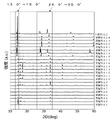
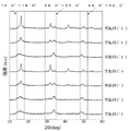
- FIG. 4 is a graph showing X-ray diffraction patterns of solid electrolyte materials according to Examples 1, 3 to 14, and 16 to 24 and Comparative Example 2.
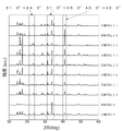
- FIG. 5 is a graph showing X-ray diffraction patterns of solid electrolyte materials according to Examples 2, 3 and 15 and Comparative Example 1.
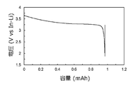
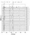
- FIG. 6 is a graph showing X-ray diffraction patterns of solid electrolyte materials according to Examples 8 to 17; 7 is a graph showing the initial discharge characteristics of the battery according to Example 1.
- FIG. FIG. 8 is a graph showing a cole-cole plot obtained by alternating current (AC) impedance measurement of the solid electrolyte material according to Example B1.
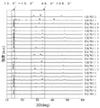
- FIG. 9 is a graph showing X-ray diffraction patterns of solid electrolyte materials according to Examples B1 to B5, B8 to B10, B12 to B22, and B24 to B33, and Comparative Examples B1 and B2.
- FIG. 10 is a graph showing X-ray diffraction patterns of solid electrolyte materials according to Examples B6, B7, B9 to B11, B19, B20, and B23, and Comparative Examples B1 and B2.
- FIG. 11 is a graph showing the initial discharge characteristics of the battery according to Example B1.
- FIG. 12 is a graph showing a cole-cole plot obtained by alternating current (AC) impedance measurement of the solid electrolyte material according to Example C1.
- FIG. 13 is a graph showing X-ray diffraction patterns of solid electrolyte materials according to Examples C1 to C4 and C11 to C13.
- FIG. 14 is a graph showing X-ray diffraction patterns of solid electrolyte materials according to Examples C5 to C10, C14, and C15.
- FIG. 15 is a graph showing the initial discharge characteristics of the battery according to Example C1.
- FIG. 16 is a graph showing a cole-cole plot obtained by alternating current (AC) impedance measurement of the solid electrolyte material according to Example D1.
- FIG. 17 is a graph showing X-ray diffraction patterns of solid electrolyte materials according to Examples D1, D2, D4, D5, D7 to D19, D22 to D24, and D26, and Comparative Examples D1 and D2.
- FIG. 18 is a graph showing X-ray diffraction patterns of solid electrolyte materials according to Examples D3, D6, D20 to D22, and D25 to D27, and Comparative Examples D1 and D2.
- FIG. 19 is a graph showing the initial discharge characteristics of the battery according to Example D1.
- the solid electrolyte material according to the first embodiment consists of Li, Yb, M, and X.
- M is at least one selected from the group consisting of Mg, Ca, Sr, Ba, Zn, Y, Tb, Gd, Sm, In, Zr, and Hf.
- X is at least one selected from the group consisting of F, Cl, Br and I;
- the solid electrolyte material according to the first embodiment is a highly useful new solid electrolyte material.
- the solid electrolyte material according to the first embodiment may for example have a practical lithium ion conductivity, for example a high lithium ion conductivity.
- the high lithium ion conductivity is, for example, 5.0 ⁇ 10 ⁇ 5 S/cm or more near room temperature (eg, 25° C.). That is, the solid electrolyte material according to the first embodiment can have an ionic conductivity of, for example, 5.0 ⁇ 10 ⁇ 5 S/cm or more.
- the solid electrolyte material according to the first embodiment can be used to obtain batteries with excellent charge/discharge characteristics.
- An example of such a battery is an all solid state battery.
- the all-solid-state battery may be a primary battery or a secondary battery.
- the solid electrolyte material according to the first embodiment does not substantially contain sulfur.
- the fact that the solid electrolyte material according to the first embodiment does not substantially contain sulfur means that the solid electrolyte material does not contain sulfur as a constituent element except sulfur that is unavoidably mixed as an impurity. In this case, sulfur mixed as an impurity in the solid electrolyte material is, for example, 1 mol % or less.
- the solid electrolyte material according to the first embodiment does not contain sulfur.
- a sulfur-free solid electrolyte material does not generate hydrogen sulfide even when exposed to the atmosphere, and is therefore excellent in safety.
- the sulfide solid electrolyte disclosed in Patent Document 1 can generate hydrogen sulfide when exposed to the air.
- the solid electrolyte material according to the first embodiment may contain elements that are unavoidably mixed. Examples of such elements are hydrogen, oxygen or nitrogen. Such elements can be present in the raw powder of the solid electrolyte material or in the atmosphere for manufacturing or storing the solid electrolyte material. In the solid electrolyte material according to the first embodiment, the elements that are unavoidably mixed as described above are, for example, 1 mol % or less.
- M may be at least one selected from the group consisting of Mg, Ca, Sr, Ba, and Zn in order to increase the ionic conductivity of the solid electrolyte material.
- M may be at least one selected from the group consisting of Mg, Ca, Sr, and Zn.
- X may be at least one selected from the group consisting of Cl, Br and I in the solid electrolyte material according to the first embodiment.
- the solid electrolyte material according to the first embodiment may be a material represented by the following compositional formula (1).
- compositional formula (1) Li 6-3a-2b Yb a M b Cl 6-xy Br x I y (1) Now the following five formulas: 0.2 ⁇ a ⁇ 1.4, 0 ⁇ b ⁇ 0.9, 0 ⁇ x ⁇ 6, 0 ⁇ y ⁇ 3, and 0 ⁇ x+y ⁇ 6 is satisfied.
- the material represented by compositional formula (1) has high ionic conductivity.
- the upper and lower limits of the range of a in composition formula (1) are 0.5, 0.6, 0.7, 0.75, 0.8, 0.85, 0.9, 1, and 1.0. It may be defined by any combination selected from one numerical value.
- the upper and lower limits of the range of b in the composition formula (1) are greater than 0 (that is, 0 ⁇ b), 0.05, 0.1, 0.15, 0.2, 0.3, 0.4 , 0.5, and 0.6.
- composition formula (1) may be defined by any combination selected from the numerical values of 0, 2, 3, and 6.
- the solid electrolyte material according to the first embodiment has higher lithium ion conductivity.
- X may be at least two selected from the group consisting of F, Cl, Br, and I in order to increase the ionic conductivity of the solid electrolyte material.
- M may contain Zn.
- M may be Zn.
- the X-ray diffraction pattern of the solid electrolyte material according to the first embodiment was obtained by X It can be obtained by line diffraction measurements.
- the obtained X-ray diffraction pattern at least one peak exists in the range of diffraction angles 2 ⁇ of 13.0° or more and 15.0° or less, and in addition, 26.0° or more and 35.0° or less. There may be at least two peaks in the range of diffraction angles 2 ⁇ .
- a crystal phase having such a peak is called a first crystal phase.
- paths for lithium ions to diffuse within the crystal are likely to be formed. Therefore, when the solid electrolyte material according to the first embodiment contains the first crystal phase, the solid electrolyte material according to the first embodiment has high ionic conductivity.
- the crystal system of the first crystal phase belongs to the monoclinic system.
- the “monoclinic crystal” in the present disclosure has a crystal structure similar to Li 3 InCl 6 disclosed in ICSD (Inorganic Crystal Structure Database) Collection Code 89617, and a crystal phase having an X-ray diffraction pattern unique to this structure. means.
- "having a similar crystal structure” means being classified into the same space group and having a close atomic arrangement structure, and does not limit lattice constants.
- the relative intensity ratio and the diffraction angle of the diffraction peaks of the X-ray diffraction pattern of the solid electrolyte material according to the first embodiment may change from the diffraction pattern of Li 3 InCl 6 .
- the solid electrolyte material according to the first embodiment In the X-ray diffraction pattern of the solid electrolyte material according to the first embodiment obtained by X-ray diffraction measurement using Cu—K ⁇ rays, at least 1 at least two peaks in the range of diffraction angles 2 ⁇ of 31.0° or more and 35.0° or less, and of diffraction angles 2 ⁇ of 40.0° or more and 42.0° or less There may be at least one peak in the range. A crystalline phase with these peaks is called a secondary crystalline phase.
- a solid electrolyte material containing a second crystal phase is likely to form a path for lithium ions to diffuse in the crystal. Therefore, when the solid electrolyte material according to the first embodiment contains the second crystal phase, the solid electrolyte material according to the first embodiment has high ionic conductivity.
- the crystal system of the second crystal phase belongs to the cubic system.
- "Orthogonal" in this disclosure means a crystalline phase that has a crystal structure similar to Li3YbCl6 disclosed in ICSD Collection Code 50152 and has an X-ray diffraction pattern unique to this structure.
- the relative intensity ratios and diffraction angles of the diffraction peaks of the X-ray diffraction pattern of the solid electrolyte material according to the first embodiment may vary from the diffraction pattern of Li 3 YbCl 6 .
- the solid electrolyte material according to the first embodiment obtained by X-ray diffraction measurement using a Cu—K ⁇ ray, at least 2 in the range of diffraction angles 2 ⁇ of 21.0° or more and 24.0° or less at least two peaks in the range of diffraction angles 2 ⁇ of 31.0° or more and 35.0° or less, and of diffraction angles 2 ⁇ of 40.0° or more and 42.0° or less There may be at least one peak in the range.
- the crystalline phase with these peaks is called the tertiary crystalline phase.
- a solid electrolyte material containing a third crystal phase is likely to form a path for lithium ions to diffuse in the crystal. Therefore, when the solid electrolyte material according to the first embodiment contains the third crystal phase, the solid electrolyte material according to the first embodiment has high ionic conductivity.
- the crystal system of the third crystal phase belongs to the trigonal system.
- "Trigonal” in this disclosure means a crystalline phase that has a similar crystal structure to Li3ErCl6 disclosed in ICSD Collection Code 50151 and has an X-ray diffraction pattern unique to this structure.
- the relative intensity ratios and diffraction angles of the diffraction peaks of the X - ray diffraction pattern of the solid electrolyte material according to the first embodiment may vary from the diffraction pattern of Li3ErCl6 .
- the solid electrolyte material according to the first embodiment may further contain a fourth crystal phase different from the first, second and third crystal phases. That is, the solid electrolyte material according to the first embodiment may further contain a fourth crystal phase having a clear peak outside the range of the diffraction angle 2 ⁇ .
- the fourth crystal phase may, for example, be attributed to a spinel structure.
- the spinel structure may be, for example, a structure similar to Li 2 ZnCl 4 disclosed in ICSD Collection Code 202743.
- M in the solid electrolyte material according to the first embodiment, M may be at least one selected from the group consisting of Y, Tb, Gd, Sm, and In. . In order to further increase the ionic conductivity of the solid electrolyte material, M may be at least one selected from the group consisting of Y, Tb, Gd, and Sm in the solid electrolyte material according to the first embodiment.
- X may be at least one selected from the group consisting of Cl, Br and I in the solid electrolyte material according to the first embodiment.
- the solid electrolyte material according to the first embodiment may be a material represented by the following compositional formula (2).
- compositional formula (2) Li 6-3a (Yb 1-b M b ) a Cl 6-xy Br x I y (2) Now the following five formulas: 0.5 ⁇ a ⁇ 1.5, 0 ⁇ b ⁇ 1, 0 ⁇ x ⁇ 6, 0 ⁇ y ⁇ 3, and 0 ⁇ x+y ⁇ 6 is satisfied.
- the material represented by compositional formula (2) has high ionic conductivity.
- the upper and lower limits of the range of b in the composition formula (2) are greater than 0 (that is, 0 ⁇ b), 0.1, 0.2, 0.3, 0.4, 0.5, 0.7 , 0.9, and any combination of numbers less than 1 (ie, b ⁇ 1).
- composition formula (2) may be defined by any combination selected from the numerical values of 0, 1, 1.5, 2, 3, and 6.
- composition formula (2) may be defined by any combination selected from numerical values of 0, 0.5, 1, and 2.
- the X-ray diffraction pattern of the solid electrolyte material according to the first embodiment was obtained by X It can be obtained by line diffraction measurements.
- the obtained X-ray diffraction pattern at least one peak exists in the range of diffraction angles 2 ⁇ of 13.0° or more and 15.0° or less, and in addition, 26.0° or more and 35.0° or less. There may be at least two peaks in the range of diffraction angles 2 ⁇ .
- a crystal phase having such a peak is called a fifth crystal phase.
- the solid electrolyte material containing the fifth crystal phase paths for lithium ions to diffuse within the crystal are likely to be formed. Therefore, when the solid electrolyte material according to the first embodiment contains the fifth crystal phase, the solid electrolyte material according to the first embodiment has high ionic conductivity.
- the crystal system of the fifth crystal phase belongs to the monoclinic system.
- the solid electrolyte material according to the first embodiment obtained by X-ray diffraction measurement using Cu—K ⁇ rays, at least 2 in the range of diffraction angles 2 ⁇ of 20.5° or more and 24.0° or less at least two peaks in the range of diffraction angles 2 ⁇ of 30.0° or more and 35.0° or less, and of diffraction angles 2 ⁇ of 39.0° or more and 42.0° or less There may be at least one peak in the range.
- the crystalline phase with these peaks is called the 6th crystalline phase.
- a solid electrolyte material containing a sixth crystal phase is likely to form a path for diffusion of lithium ions in the crystal. Therefore, when the solid electrolyte material according to the first embodiment contains the sixth crystal phase, the solid electrolyte material according to the first embodiment has high ionic conductivity.
- the crystal system of the sixth crystal phase belongs to the trigonal system.
- the solid electrolyte material according to the first embodiment may further contain a seventh crystal phase different from the fifth and sixth crystal phases. That is, the solid electrolyte material according to the first embodiment may further contain a seventh crystal phase in which a clear peak is present outside the diffraction angle 2 ⁇ range described above.
- the seventh crystal phase for example, belongs to a crystal structure similar to Li3YbCl6 disclosed in ICSD Collection Code 50152 or a crystal structure similar to LiGdCl4 disclosed in ICSD Collection Code 38326.
- M may be at least one selected from the group consisting of Zr and Hf in the solid electrolyte material according to the first embodiment.
- X may be at least one selected from the group consisting of Cl, Br and I in the solid electrolyte material according to the first embodiment.
- the solid electrolyte material according to the first embodiment may be a material represented by the following compositional formula (3).
- compositional formula (3) Li 6-3a-4b Yb a M b Cl 6-xy Br x I y (3) Now the following six formulas: 0 ⁇ a ⁇ 1.5, 0 ⁇ b ⁇ 1.5, 0 ⁇ 3a+4b ⁇ 6 0 ⁇ x ⁇ 6, 0 ⁇ y ⁇ 3, and 0 ⁇ x+y ⁇ 6 is satisfied.
- the material represented by compositional formula (3) has high ionic conductivity.
- the upper and lower limits of the range of a in the composition formula (3) are greater than 0 (that is, 0 ⁇ a), 0.1, 0.3, 0.4, 0.5, 0.55, 0.6 , 0.7, 0.8, 0.9, and any combination of numbers less than 1 (ie, a ⁇ 1).
- the upper and lower limits of the range of b in the composition formula (3) are greater than 0 (that is, 0 ⁇ b), 0.1, 0.3, 0.35, 0.4, 0.45, 0.5 , 0.6, 0.9, and any combination of numbers less than 1 (ie, b ⁇ 1).
- 0 ⁇ b ⁇ 1 may be satisfied in the composition formula (3).
- the upper limit and lower limit of the range of x in composition formula (3) may be defined by any combination selected from numerical values of 0, 1, 2, 3, 4, and 6.
- composition formula (3) may be defined by any combination selected from the numerical values of 0, 1, and 2.
- composition formula (3) In order to increase the ionic conductivity of the solid electrolyte material, 0 ⁇ y ⁇ 2 may be satisfied in the composition formula (3). In order to increase the ionic conductivity of the solid electrolyte material, y>0 may be satisfied in the compositional formula (3).
- a ⁇ 0.7 and b ⁇ 0.3 may be satisfied in the composition formula (3).
- the X-ray diffraction pattern of the solid electrolyte material according to the first embodiment was obtained by X It can be obtained by line diffraction measurements.
- diffraction angles 2 ⁇ of 14.0° or more and 18.0° or less, 29.0° or more and 35.0° or less, and 48.0° or more and 52.0° or less
- a crystal phase having such a peak is called an eighth crystal phase.
- a solid electrolyte material containing the eighth crystal phase is likely to form a path for lithium ions to diffuse in the crystal. Therefore, when the solid electrolyte material according to the first embodiment contains the first crystal phase, the solid electrolyte material according to the first embodiment has high ionic conductivity.
- the solid electrolyte material according to the first embodiment In the X-ray diffraction pattern of the solid electrolyte material according to the first embodiment obtained by X-ray diffraction measurement using Cu—K ⁇ rays, at least 2 in the range of diffraction angles 2 ⁇ of 26.0° or more and 35.0° or less There may be two peaks, and at least one peak may be present in the diffraction angle 2 ⁇ range of 13.0° or more and 17.0° or less. The crystalline phase with these peaks is called the ninth crystalline phase.
- a solid electrolyte material containing a second crystal phase is likely to form a path for lithium ions to diffuse in the crystal. Therefore, when the solid electrolyte material according to the first embodiment contains the ninth crystal phase, the solid electrolyte material according to the first embodiment has high ionic conductivity.
- the solid electrolyte material according to the first embodiment may further contain a tenth crystal phase different from the eighth and ninth crystal phases. That is, the solid electrolyte material according to the first embodiment may further contain a tenth crystal phase in which a clear peak is present outside the diffraction angle 2 ⁇ range described above.
- M consists of M1 and M2, and M1 is selected from the group consisting of Y, Tb, Gd, Sm, and In. and M2 may be at least one selected from the group consisting of Mg, Ca, Sr, Ba, and Zn.
- M1 may be one selected from the group consisting of Y, Tb, Gd, and Sm in the solid electrolyte material according to the first embodiment.
- M2 may be at least one selected from the group consisting of Mg, Ca, Sr, and Zn in the solid electrolyte material according to the first embodiment.
- M2 may be at least one selected from the group consisting of Mg, Sr, and Zn.
- X may be at least one selected from the group consisting of Cl and Br in the solid electrolyte material according to the first embodiment.
- the solid electrolyte material according to the first embodiment may be a material represented by the following compositional formula (4).
- the material represented by compositional formula (4) has high ionic conductivity.
- the upper and lower limits of the range of b in the composition formula (4) are arbitrary values selected from values greater than 0 (that is, 0 ⁇ b), 0.1, 0.2, 0.25, and 0.3 may be defined by a combination of
- the upper and lower limits of the range of c in the composition formula (4) are arbitrary values selected from values greater than 0 (that is, 0 ⁇ c), 0.05, 0.1, 0.15, and 0.2 may be defined by a combination of
- composition formula (4) In order to increase the ionic conductivity of the solid electrolyte material, 0 ⁇ c ⁇ 0.2 may be satisfied in the composition formula (4). In order to further increase the ionic conductivity of the solid electrolyte material, 0 ⁇ c ⁇ 0.1 may be satisfied in composition formula (4).
- composition formula (4) may be defined by any combination selected from the numerical values of 0, 1, 3, and 6.
- the X-ray diffraction pattern of the solid electrolyte material according to the first embodiment was obtained by X It can be obtained by line diffraction measurements.
- the obtained X-ray diffraction pattern at least one peak exists in the range of the diffraction angle 2 ⁇ of 13.0° or more and 15.0° or less, and the diffraction angle 2 ⁇ is 26.0° or more and 35.0° or less. At least two peaks may be present in the range of 2 ⁇ .
- a crystal phase having such a peak is called an eleventh crystal phase.
- the solid electrolyte material containing the eleventh crystal phase paths for lithium ions to diffuse within the crystal are likely to be formed. Therefore, when the solid electrolyte material according to the first embodiment contains the eleventh crystal phase, the solid electrolyte material according to the first embodiment has high ionic conductivity.
- the crystal system of the eleventh crystal phase belongs to the monoclinic system.
- the solid electrolyte material according to the first embodiment obtained by X-ray diffraction measurement using Cu—K ⁇ rays, at least 2 in the range of diffraction angles 2 ⁇ of 20.5° or more and 24.0° or less at least two peaks in the range of diffraction angles 2 ⁇ of 30.0° or more and 35.0° or less, and of diffraction angles 2 ⁇ of 39.0° or more and 42.0° or less There may be at least one peak in the range.
- the crystalline phase with these peaks is called the 12th crystalline phase.
- a solid electrolyte material containing a twelfth crystal phase is likely to form a path for lithium ions to diffuse in the crystal. Therefore, when the solid electrolyte material according to the first embodiment contains the twelfth crystal phase, the solid electrolyte material according to the first embodiment has high ionic conductivity.
- the crystal system of the 12th crystal phase belongs to the trigonal system.
- the solid electrolyte material according to the first embodiment may further contain a thirteenth crystal phase different from the eleventh and twelfth crystal phases. That is, the solid electrolyte material according to the first embodiment may further contain a thirteenth crystal phase having a clear peak outside the diffraction angle 2 ⁇ range described above.
- the thirteenth crystal phase for example, belongs to a crystal structure similar to Li3YbCl6 disclosed in ICSD Collection Code 50152 or a crystal structure similar to LiGdCl4 disclosed in ICSD Collection Code 38326.
- the solid electrolyte material according to the first embodiment may be crystalline or amorphous. Further, the solid electrolyte material according to the first embodiment may be a mixture of crystalline and amorphous.
- crystalline refers to the presence of peaks in the X-ray diffraction pattern.
- Amorphous refers to the presence of broad peaks (ie halos) in the X-ray diffraction pattern. When amorphous and crystalline are mixed, there are peaks and halos in the X-ray diffraction pattern.
- the shape of the solid electrolyte material according to the first embodiment is not limited. Examples of such shapes are acicular, spherical, or ellipsoidal.
- the solid electrolyte material according to the first embodiment may be particles.
- the solid electrolyte material according to the first embodiment may be formed to have a pellet or plate shape.
- the solid electrolyte material may have a median diameter of 0.1 ⁇ m or more and 100 ⁇ m or less.
- Median size means the particle size when the cumulative volume in a volume-based particle size distribution is equal to 50%.
- the volume-based particle size distribution is measured by, for example, a laser diffraction measurement device or an image analysis device.
- the solid electrolyte material according to the first embodiment may have a median diameter of 0.5 ⁇ m or more and 10 ⁇ m or less. Thereby, the solid electrolyte material according to the first embodiment has higher ionic conductivity. Furthermore, when the solid electrolyte material according to the first embodiment is mixed with another material such as an active material, the solid electrolyte material according to the first embodiment and the other material are well dispersed.
- the solid electrolyte material according to the first embodiment is produced, for example, by the following method.
- Two or more halide raw material powders are mixed so as to have the desired composition.
- LiCl raw powder , YbCl3 raw powder, and MgCl2 raw powder are mixed so as to have a molar ratio of approximately 3.15:0.85:0.15.
- the raw material powders may be mixed in pre-adjusted molar ratios to compensate for possible compositional changes in the synthesis process.
- a mixture of raw material powders is fired in an inert gas atmosphere to react with each other to obtain a reactant.
- Helium, nitrogen, or argon, for example, can be used as inert gases.
- the firing step may be performed in vacuum.
- the mixed material powder may be placed in a container (eg, a crucible or a sealed tube) and fired in a heating furnace.
- the raw material powders may be mechanochemically reacted with each other in a mixing device such as a planetary ball mill (that is, using a mechanochemical milling method) to obtain a reactant.
- a mixing device such as a planetary ball mill (that is, using a mechanochemical milling method) to obtain a reactant.
- the mechanochemically obtained reactant may be further calcined in an inert gas atmosphere or in vacuum.
- the solid electrolyte material according to the first embodiment is obtained.
- the second embodiment describes a battery using the solid electrolyte material according to the first embodiment.
- a battery according to the second embodiment includes a positive electrode, a negative electrode, and an electrolyte layer.
- the electrolyte layer is provided between the positive electrode and the negative electrode.
- At least one selected from the group consisting of the positive electrode, the electrolyte layer, and the negative electrode contains the solid electrolyte material according to the first embodiment.
- the battery according to the second embodiment contains the solid electrolyte material according to the first embodiment, it has excellent charge/discharge characteristics.
- the battery may be an all solid state battery.
- FIG. 1 shows a cross-sectional view of a battery 1000 according to the second embodiment.
- a battery 1000 according to the second embodiment includes a positive electrode 201 , an electrolyte layer 202 and a negative electrode 203 .
- Electrolyte layer 202 is provided between positive electrode 201 and negative electrode 203 .
- the positive electrode 201 contains positive electrode active material particles 204 and solid electrolyte particles 100 .
- the electrolyte layer 202 contains an electrolyte material.
- the electrolyte material is, for example, a solid electrolyte material.
- the negative electrode 203 contains negative electrode active material particles 205 and solid electrolyte particles 100 .
- the solid electrolyte particles 100 are particles containing the solid electrolyte material according to the first embodiment.
- the solid electrolyte particles 100 may be particles made of the solid electrolyte material according to the first embodiment, or particles containing the solid electrolyte material according to the first embodiment as a main component.
- particles containing the solid electrolyte material according to the first embodiment as a main component means particles in which the component contained in the largest molar ratio is the solid electrolyte material according to the first embodiment.
- the solid electrolyte particles 100 may have a median diameter of 0.1 ⁇ m or more and 100 ⁇ m or less, or may have a median diameter of 0.5 ⁇ m or more and 10 ⁇ m or less. In this case, the solid electrolyte particles 100 have higher ionic conductivity.
- the positive electrode 201 contains a material that can occlude and release metal ions (eg, lithium ions).
- the material is, for example, a positive electrode active material (eg, positive electrode active material particles 204).
- positive electrode active materials are lithium-containing transition metal oxides, transition metal fluorides, polyanion materials, fluorinated polyanion materials, transition metal sulfides, transition metal oxyfluorides, transition metal oxysulfides, or transition metal oxynitrides. be.
- lithium - containing transition metal oxides are Li(Ni,Co,Al) O2 or LiCoO2.
- the notation "(A, B, C)" in the chemical formula means "at least one selected from the group consisting of A, B, and C".
- “(Ni, Co, Al)” is synonymous with “at least one selected from the group consisting of Ni, Co, and Al”.
- the positive electrode active material particles 204 may have a median diameter of 0.1 ⁇ m or more and 100 ⁇ m or less. When the positive electrode active material particles 204 have a median diameter of 0.1 ⁇ m or more, the positive electrode active material particles 204 and the solid electrolyte particles 100 are well dispersed in the positive electrode 201 . This improves the charge/discharge characteristics of the battery. When the positive electrode active material particles 204 have a median diameter of 100 ⁇ m or less, the diffusion rate of lithium in the positive electrode active material particles 204 is improved. This allows the battery to operate at high output.
- the positive electrode active material particles 204 may have a larger median diameter than the solid electrolyte particles 100 . As a result, the positive electrode active material particles 204 and the solid electrolyte particles 100 are dispersed well in the positive electrode 201 .
- the ratio of the volume of the positive electrode active material particles 204 to the sum of the volume of the positive electrode active material particles 204 and the volume of the solid electrolyte particles 100 is 0.30 or more and 0.30. It may be 95 or less.
- the positive electrode 201 may have a thickness of 10 ⁇ m or more and 500 ⁇ m or less.
- the electrolyte layer 202 contains an electrolyte material.
- the electrolyte material is, for example, the solid electrolyte material according to the first embodiment.
- the electrolyte layer 202 may be a solid electrolyte layer.
- the electrolyte layer 202 may be composed only of the solid electrolyte material according to the first embodiment. Alternatively, the electrolyte layer 202 may be composed only of a solid electrolyte material different from the solid electrolyte material according to the first embodiment.
- solid electrolyte materials different from the solid electrolyte material according to the first embodiment are Li 2 MgX′ 4 , Li 2 FeX′ 4 , Li(Al, Ga, In)X′ 4 , Li 3 (Al, Ga, In ) X′ 6 , or LiI.
- X' is at least one selected from the group consisting of F, Cl, Br and I.
- the solid electrolyte material different from the solid electrolyte material according to the first embodiment may be a solid electrolyte containing a halogen element, that is, a halide solid electrolyte.
- the solid electrolyte material according to the first embodiment is hereinafter referred to as the first solid electrolyte material.
- a solid electrolyte material different from the solid electrolyte material according to the first embodiment is called a second solid electrolyte material.
- the electrolyte layer 202 may contain not only the first solid electrolyte material but also the second solid electrolyte material.
- the first solid electrolyte material and the second solid electrolyte material may be uniformly dispersed in the electrolyte layer 202 .
- a layer made of the first solid electrolyte material and a layer made of the second solid electrolyte material may be stacked along the stacking direction of battery 1000 .
- the electrolyte layer 202 may have a thickness of 1 ⁇ m or more and 1000 ⁇ m or less. When the electrolyte layer 202 has a thickness of 1 ⁇ m or more, the short circuit between the positive electrode 201 and the negative electrode 203 is less likely to occur. If the electrolyte layer 202 has a thickness of 1000 ⁇ m or less, the battery can operate at high power.
- the negative electrode 203 contains a material capable of intercalating and deintercalating metal ions such as lithium ions.
- the material is, for example, a negative electrode active material (eg, negative electrode active material particles 205).
- Examples of negative electrode active materials are metal materials, carbon materials, oxides, nitrides, tin compounds, or silicon compounds.
- the metallic material may be a single metal or an alloy.
- Examples of metallic materials are lithium metal or lithium alloys.
- Examples of carbon materials are natural graphite, coke, ungraphitized carbon, carbon fibers, spherical carbon, artificial graphite, or amorphous carbon. From the viewpoint of capacity density, suitable examples of negative electrode active materials are silicon (ie, Si), tin (ie, Sn), silicon compounds, or tin compounds.
- the negative electrode active material particles 205 may have a median diameter of 0.1 ⁇ m or more and 100 ⁇ m or less. When the negative electrode active material particles 205 have a median diameter of 0.1 ⁇ m or more, the negative electrode active material particles 205 and the solid electrolyte particles 100 are well dispersed in the negative electrode 203 . This improves the charge/discharge characteristics of the battery. When the negative electrode active material particles 205 have a median diameter of 100 ⁇ m or less, the diffusion rate of lithium in the negative electrode active material particles 205 is improved. This allows the battery to operate at high output.
- the negative electrode active material particles 205 may have a larger median diameter than the solid electrolyte particles 100 . Thereby, in the negative electrode 203, the dispersion state of the negative electrode active material particles 205 and the solid electrolyte particles 100 is improved.
- the ratio of the volume of the negative electrode active material particles 205 to the total volume of the negative electrode active material particles 205 and the volume of the solid electrolyte particles 100 is 0.30 or more and 0.30. It may be 95 or less.
- the negative electrode 203 may have a thickness of 10 ⁇ m or more and 500 ⁇ m or less.
- At least one selected from the group consisting of positive electrode 201, electrolyte layer 202, and negative electrode 203 contains a second solid electrolyte material for the purpose of enhancing ion conductivity, chemical stability, and electrochemical stability. may be
- the second solid electrolyte material may be a halide solid electrolyte.
- halide solid electrolytes are Li 2 MgX′ 4 , Li 2 FeX′ 4 , Li(Al,Ga,In)X′ 4 , Li 3 (Al,Ga,In)X′ 6 or LiI.
- X' is at least one selected from the group consisting of F, Cl, Br and I.
- halide solid electrolyte is the compound represented by Li p Me q Y r Z 6 .
- Me is at least one element selected from the group consisting of metal elements other than Li and Y and metalloid elements.
- the value of m' represents the valence of Me.
- Z is at least one selected from the group consisting of F, Cl, Br and I; "Semimetallic elements" are B, Si, Ge, As, Sb, and Te.
- Metallic element means all elements contained in Groups 1 to 12 of the periodic table (excluding hydrogen), and all elements contained in Groups 13 to 16 of the periodic table (where B, Si, Ge, As, Sb, Te, C, N, P, O, S, and Se).
- Me is selected from the group consisting of Mg, Ca, Sr, Ba, Zn, Sc, Al, Ga, Bi, Zr, Hf, Ti, Sn, Ta, and Nb. At least one may be selected.
- the second solid electrolyte material may be a sulfide solid electrolyte.
- Examples of sulfide solid electrolytes are Li 2 S—P 2 S 5 , Li 2 S—SiS 2 , Li 2 S—B 2 S 3 , Li 2 S—GeS 2 , Li 3.25 Ge 0.25 P 0 .75 S 4 , or Li 10 GeP 2 S 12 .
- the second solid electrolyte material may be an oxide solid electrolyte.
- oxide solid electrolytes are (i) NASICON - type solid electrolytes such as LiTi2(PO4)3 or elemental substitutions thereof; (ii) perovskite-type solid electrolytes such as (LaLi) TiO3 , ( iii) LISICON - type solid electrolytes such as Li14ZnGe4O16 , Li4SiO4 , LiGeO4 or elemental substitutions thereof; ( iv ) garnet - type solid electrolytes such as Li7La3Zr2O12 or its elemental substitutions, or ( v) Li3PO4 or its N substitutions.
- NASICON - type solid electrolytes such as LiTi2(PO4)3 or elemental substitutions thereof
- perovskite-type solid electrolytes such as (LaLi) TiO3 ,
- LISICON - type solid electrolytes such as Li14ZnGe4O16 , Li4SiO4 , LiGeO4 or
- the second solid electrolyte material may be an organic polymer solid electrolyte.
- organic polymer solid electrolytes examples include polymeric compounds and lithium salt compounds.
- the polymer compound may have an ethylene oxide structure. Since a polymer compound having an ethylene oxide structure can contain a large amount of lithium salt, the ionic conductivity can be further increased.
- lithium salts are LiPF6 , LiBF4 , LiSbF6 , LiAsF6 , LiSO3CF3, LiN(SO2CF3)2 , LiN ( SO2C2F5 ) 2 , LiN ( SO2CF3 ). ( SO2C4F9 ) , or LiC ( SO2CF3 ) 3 .
- One lithium salt selected from these may be used alone. Alternatively, a mixture of two or more lithium salts selected from these may be used.
- At least one selected from the group consisting of the positive electrode 201, the electrolyte layer 202, and the negative electrode 203 is composed of a non-aqueous electrolyte liquid, a gel electrolyte, or an ion electrolyte for the purpose of facilitating the transfer of lithium ions and improving the output characteristics of the battery. It may contain liquids.
- the non-aqueous electrolyte contains a non-aqueous solvent and a lithium salt dissolved in the non-aqueous solvent.
- non-aqueous solvents examples include cyclic carbonate solvents, chain carbonate solvents, cyclic ether solvents, chain ether solvents, cyclic ester solvents, chain ester solvents, or fluorine solvents.
- cyclic carbonate solvents are ethylene carbonate, propylene carbonate, or butylene carbonate.
- linear carbonate solvents are dimethyl carbonate, ethyl methyl carbonate, or diethyl carbonate.
- examples of cyclic ether solvents are tetrahydrofuran, 1,4-dioxane, or 1,3-dioxolane.
- linear ether solvents are 1,2-dimethoxyethane or 1,2-diethoxyethane.
- An example of a cyclic ester solvent is ⁇ -butyrolactone.
- An example of a linear ester solvent is methyl acetate.
- fluorosolvents are fluoroethylene carbonate, methyl fluoropropionate, fluorobenzene, fluoroethyl methyl carbonate, or fluorodimethylene carbonate.
- One non-aqueous solvent selected from these may be used alone. Alternatively, a mixture of two or more non-aqueous solvents selected from these may be used.
- lithium salts are LiPF6 , LiBF4 , LiSbF6 , LiAsF6 , LiSO3CF3, LiN(SO2CF3)2 , LiN ( SO2C2F5 ) 2 , LiN ( SO2CF3 ). ( SO2C4F9 ) , or LiC ( SO2CF3 ) 3 .
- One lithium salt selected from these may be used alone. Alternatively, a mixture of two or more lithium salts selected from these may be used.
- the lithium salt concentration is, for example, 0.5 mol/liter or more and 2 mol/liter or less.
- a polymer material impregnated with a non-aqueous electrolyte can be used as the gel electrolyte.
- examples of polymeric materials are polyethylene oxide, polyacrylonitrile, polyvinylidene fluoride, polymethyl methacrylate, or polymers with ethylene oxide linkages.
- ionic liquids examples include (i) aliphatic chain quaternary salts such as tetraalkylammonium or tetraalkylphosphonium; (ii) aliphatic cyclic ammoniums such as pyrrolidiniums, morpholiniums, imidazoliniums, tetrahydropyrimidiniums, piperaziniums, or piperidiniums; or (iii) nitrogen-containing heterogeneous compounds such as pyridiniums or imidazoliums It is a ring aromatic cation.
- aliphatic chain quaternary salts such as tetraalkylammonium or tetraalkylphosphonium
- aliphatic cyclic ammoniums such as pyrrolidiniums, morpholiniums, imidazoliniums, tetrahydropyrimidiniums, piperaziniums, or piperidiniums
- nitrogen-containing heterogeneous compounds
- Examples of anions contained in ionic liquids are PF 6 ⁇ , BF 4 ⁇ , SbF 6 ⁇ , AsF 6 ⁇ , SO 3 CF 3 ⁇ , N(SO 2 CF 3 ) 2 ⁇ , N(SO 2 C 2 F 5 ) 2 ⁇ , N(SO 2 CF 3 )(SO 2 C 4 F 9 ) ⁇ , or C(SO 2 CF 3 ) 3 ⁇ .
- the ionic liquid may contain a lithium salt.
- At least one selected from the group consisting of the positive electrode 201, the electrolyte layer 202, and the negative electrode 203 may contain a binder for the purpose of improving adhesion between particles.
- binders include polyvinylidene fluoride, polytetrafluoroethylene, polyethylene, polypropylene, aramid resin, polyamide, polyimide, polyamideimide, polyacrylonitrile, polyacrylic acid, polyacrylic acid methyl ester, polyacrylic acid ethyl ester, Polyacrylic acid hexyl ester, polymethacrylic acid, polymethacrylic acid methyl ester, polymethacrylic acid ethyl ester, polymethacrylic acid hexyl ester, polyvinyl acetate, polyvinylpyrrolidone, polyether, polyether sulfone, hexafluoropolypropylene, styrene-butadiene rubber , or carboxymethyl cellulose.
- Copolymers can also be used as binders.
- binders are tetrafluoroethylene, hexafluoroethylene, hexafluoropropylene, perfluoroalkyl vinyl ethers, vinylidene fluoride, chlorotrifluoroethylene, ethylene, propylene, pentafluoropropylene, fluoromethyl vinyl ether, acrylic acid , and hexadiene.
- a mixture of two or more selected from the above materials may be used as the binder.
- At least one selected from the positive electrode 201 and the negative electrode 203 may contain a conductive aid for the purpose of increasing electronic conductivity.
- Examples of conductive aids are (i) graphites such as natural or artificial graphite; (ii) carbon blacks such as acetylene black or ketjen black; (iii) conductive fibers such as carbon or metal fibers; (iv) carbon fluoride, (v) metal powders such as aluminum, (vi) conductive whiskers such as zinc oxide or potassium titanate; (vii) conductive metal oxides such as titanium oxide; or (viii) conductive polymeric compounds such as polyaniline, polypyrrole, or polythiophene.
- the conductive aid (i) or (ii) may be used.
- Examples of the shape of the battery according to the second embodiment are coin-shaped, cylindrical, rectangular, sheet-shaped, button-shaped, flat-shaped, and laminated.
- a material for forming a positive electrode, a material for forming an electrolyte layer, and a material for forming a negative electrode are prepared, and the positive electrode, the electrolyte layer, and the negative electrode are arranged in this order by a known method. It may also be manufactured by making laminated laminates.
- the solid electrolyte material according to Example A can be represented by the compositional formula (1) above.
- Example A1> (Preparation of solid electrolyte material)
- a molar ratio of 85:0.15 was provided.
- These raw material powders were ground and mixed in an agate mortar.
- the obtained mixed powder was placed in an alumina crucible and fired at 600° C. for 1 hour in a dry argon atmosphere.
- the fired product obtained was ground in an agate mortar.
- a solid electrolyte material powder according to Example A1 was obtained.
- the solid electrolyte material according to Example A1 had a composition represented by Li3.15Yb0.85Mg0.15Cl6 .
- FIG. 2 shows a schematic diagram of a pressure forming die 300 used to evaluate the ionic conductivity of solid electrolyte materials.
- the pressure forming die 300 had a punch upper part 301 , a frame mold 302 and a punch lower part 303 . Both the punch upper portion 301 and the punch lower portion 303 were made of electronically conductive stainless steel.
- the frame mold 302 was made of insulating polycarbonate.
- the ionic conductivity of the solid electrolyte material according to Example A1 was evaluated by the following method.
- the powder of the solid electrolyte material according to Example A1 was filled inside the pressure molding die 300 . Inside the pressing die 300, a pressure of 360 MPa was applied to the powder 101 of the solid electrolyte material according to Example A1 using an upper punch 301 and a lower punch 303.
- the upper punch 301 and lower punch 303 were connected to a potentiostat (Princeton Applied Research, VersaSTAT4) equipped with a frequency response analyzer.
- the punch upper part 301 was connected to the working electrode and the terminal for potential measurement.
- the punch bottom 303 was connected to the counter and reference electrodes.
- the impedance of the solid electrolyte material was measured by electrochemical impedance measurement at room temperature.
- FIG. 3 is a graph showing a Cole-Cole plot obtained by AC impedance measurement of the solid electrolyte material according to Example A1.
- the real value of the impedance at the measurement point where the absolute value of the phase of the complex impedance was the smallest was regarded as the resistance to ion conduction of the solid electrolyte material. See arrow R SE shown in FIG. 3 for the real value.
- the ionic conductivity was calculated based on the following formula (5) using the resistance value.
- ⁇ (R SE ⁇ S/t) ⁇ 1 (5)
- ⁇ represents ionic conductivity.
- S represents the contact area of the solid electrolyte material with the punch upper part 301 . That is, S is equal to the cross-sectional area of the hollow portion of the frame mold 302 in FIG.
- R SE represents the resistance value of the solid electrolyte material in impedance measurements.
- t represents the thickness of the solid electrolyte material. That is, t is equal to the thickness of the layer formed from the solid electrolyte material powder 101 in FIG.
- FIG. 4 is a graph showing the X-ray diffraction pattern of the solid electrolyte material according to Example A1. The results shown in Figure 4 were measured by the following method.
- the X-ray diffraction pattern of the solid electrolyte material according to Example A1 was measured using an X-ray diffractometer (MiniFlex 600, Rigaku) in a dry environment with a dew point of -50°C or less.
- the X-ray diffraction pattern was measured by the ⁇ -2 ⁇ method using Cu-K ⁇ rays (wavelengths of 1.5405 ⁇ and 1.5444 ⁇ ) as the X-ray source.
- the solid electrolyte material according to Example A1 contained the first crystalline phase (ie monoclinic). Observed clear X-ray diffraction peak angles derived from the first crystal phase are shown in Table 2.
- the solid electrolyte material (80 mg) according to Example A1 and the above mixture (10 mg) were layered in this order.
- a pressure of 720 MPa was applied to the obtained laminate to form a solid electrolyte layer formed from the solid electrolyte material according to Example A1 and a positive electrode formed from the above mixture.
- the solid electrolyte layer had a thickness of 400 ⁇ m.
- current collectors made of stainless steel were attached to the positive and negative electrodes, and current collecting leads were attached to the current collectors.
- Example A1 a battery according to Example A1 was obtained.
- FIG. 5 is a graph showing the initial discharge characteristics of the battery according to Example A1. Initial charge/discharge characteristics were measured by the following method.
- Example A1 The battery according to Example A1 was placed in a constant temperature bath at 25°C.
- Example A1 The cell according to Example A1 was then discharged at a current density of 54 ⁇ A/cm 2 until a voltage of 1.88 V was reached.
- the battery according to Example A1 had an initial discharge capacity of 0.97 mAh.
- Example A2 to A17 the raw material powder mixture was fired at 600°C for 1 hour in a dry argon atmosphere.
- Example A20 the raw material powder mixture was fired at 480°C for 1 hour in a dry argon atmosphere.
- Solid electrolyte materials according to Examples A2 to A24 were obtained in the same manner as in Example A1 except for the above matters.
- FIG. 4 to 6 are graphs showing X-ray diffraction patterns of solid electrolyte materials according to Examples A2 to A24. Specifically, FIG. 4 is a graph showing X-ray diffraction patterns of solid electrolyte materials according to Examples A3 to A14 and A16 to A24.
- FIG. 5 is a graph showing X-ray diffraction patterns of solid electrolyte materials according to Examples A2, A3, and A15.
- FIG. 6 is a graph showing X-ray diffraction patterns of solid electrolyte materials according to Examples A8 to A17. Examples A4 to A7 and A18 to A24 contained the first crystalline phase.
- Example A2 had a second crystalline phase.
- Example A3 contained a first crystalline phase and a second crystalline phase.
- Examples A8 through A14, A16, and A17 contained the first and third crystalline phases.
- Example A15 contained a second crystalline phase and a third crystalline phase.
- the observed peak angles from the first, second, and third crystalline phases are shown in Tables 2 to 4, respectively.
- Batteries of Examples A2 to A24 were obtained in the same manner as in Example 1 using the solid electrolyte materials of Examples A2 to A24. Using the batteries according to Examples A2 to A24, charge-discharge tests were carried out in the same manner as in Example A1. As a result, the batteries according to Examples A2 to A24 were charged and discharged as well as the battery according to Example A1.
- Comparative Examples A1 and A2> (Preparation of solid electrolyte material)
- the raw material powder mixture was sintered at 600° C. for 1 hour in a dry argon atmosphere.
- FIG. 5 is a graph showing the X-ray diffraction pattern of the solid electrolyte material according to Comparative Example A1.
- FIG. A4 is a graph showing the X-ray diffraction pattern of the solid electrolyte material according to Comparative Example A2.
- the solid electrolyte material according to Comparative Example A1 contained a second crystal phase.
- the solid electrolyte material according to Comparative Example A2 contained a first crystal phase.
- the observed X-ray diffraction peak angles from the first and second crystalline phases are shown in Tables 2 and 3.
- compositions of the solid electrolyte materials of Example A and Comparative Example A are shown in Table 1. Also, Table 1 shows the values corresponding to a, b, x, and y in the composition formula (1) and the element type of M.
- the solid electrolyte materials according to Examples A1 to A24 have a high lithium ion conductivity of 5.0 ⁇ 10 ⁇ 5 S/cm or more near room temperature.
- the batteries according to Examples A1 to A24 were charged and discharged at room temperature.
- the solid electrolyte material according to Example B can be represented by the compositional formula (2) above.
- Example B1> (Preparation of solid electrolyte material)
- These raw material powders were ground and mixed in an agate mortar.
- the obtained mixed powder was placed in an alumina crucible and fired in a dry argon atmosphere at 550° C. for 1 hour. The fired product obtained was ground in an agate mortar.
- the solid electrolyte material powder according to Example 1 was obtained.
- the solid electrolyte material according to Example B1 had a composition represented by Li3Yb0.9Y0.1Br1Cl5 .
- FIG. 8 is a graph showing a Cole-Cole plot obtained by AC impedance measurement of the solid electrolyte material according to Example B1.
- FIG. 9 is a graph showing the X-ray diffraction pattern of the solid electrolyte material according to Example B1. The results shown in FIG. 9 were measured in the same manner as in Example A1.
- the solid electrolyte material according to Example B1 contained the fifth crystal phase (ie monoclinic). Observed distinct X-ray diffraction peak angles derived from the fifth crystal phase are shown in Table 6.
- Example B1 (Production of battery) A battery of Example B1 was obtained in the same manner as in Example A1, except that the solid electrolyte material of Example B1 was used instead of the solid electrolyte material of Example A1.
- FIG. 11 is a graph showing the initial discharge characteristics of the battery according to Example B1. The initial charge/discharge characteristics were measured in the same manner as in Example A1.
- the battery according to Example B1 had an initial discharge capacity of 0.84 mAh.
- Example B23 the raw material powder mixture was fired at 600°C for 1 hour in a dry argon atmosphere.
- Example B25 to B30 the raw material powder mixture was fired at 480°C for 1 hour in a dry argon atmosphere.
- Example B31 the raw material powder mixture was fired at 350°C for 5 hours in a dry argon atmosphere.
- FIG. 9 and 10 are graphs showing X-ray diffraction patterns of solid electrolyte materials according to Examples B2 to B33. Specifically, FIG. 9 is a graph showing the X-ray diffraction patterns of solid electrolyte materials according to Examples B2 to B5, B8 to B10, B12 to B22, and B24 to B33.
- FIG. 10 is a graph showing X-ray diffraction patterns of solid electrolyte materials according to Examples B6, B7, B9 to B11, B19, B20, and B23. Examples B2 to B5, B8, B12 to B18, B21, B22, and B24 to B33 contained the fifth crystalline phase. Examples B6, B7, B11, and B23 contained a sixth crystalline phase. Examples B9, B10, B19, and B20 contained the fifth and sixth crystalline phases. The observed peak angles from the fifth and sixth crystalline phases are shown in Tables 6 and 7, respectively.
- FIGS. 9 and 10 are graphs showing X-ray diffraction patterns of solid electrolyte materials according to Comparative Examples B1 and B2.
- the solid electrolyte material according to Comparative Example B2 contained a fifth crystal phase.
- the solid electrolyte material according to Comparative Example B1 had a structure similar to Li 3 YbCl 6 disclosed in ICSD Collection Code 50152. Table 6 shows the X-ray diffraction peak angles derived from the fifth crystal phase observed in Comparative Example B2.
- compositions of the solid electrolyte materials according to Example B and Comparative Example B are shown in Table 5. Also, Table 5 shows the values corresponding to a, b, x, and y in the composition formula (2) and the element type of M.
- the solid electrolyte materials according to Examples B1 to B33 have a high lithium ion conductivity of 5.0 ⁇ 10 ⁇ 5 S/cm or more near room temperature.
- the solid electrolyte material has higher ionic conductivity when 0 ⁇ x ⁇ 6 is satisfied. It is considered that this is because when X contains two or more elements, a path for diffusion of lithium ions is easily formed in the crystal lattice.
- the solid electrolyte material has high ionic conductivity. Also, the solid electrolyte material has a higher ionic conductivity, especially when the value of y is 1, as is evident when Examples B28 and B29 are compared with Examples B14, B26, and B30. It is believed that this is because when the amount of I is 1 mol, the path for diffusion of lithium ions in the crystal lattice is optimized.
- the solid electrolyte material has higher ionic conductivity when M is Y, Gd, Tb, or Sm.
- M is Y, Gd, or Tb
- the solid electrolyte material has even higher ionic conductivity.
- the batteries according to Examples B1 to B33 were charged and discharged at room temperature.
- the solid electrolyte material according to Example C can be represented by the compositional formula (3) above.
- Example C1> (Preparation of solid electrolyte material)
- These raw material powders were ground and mixed in an agate mortar.
- the obtained mixed powder was milled at 500 rpm for 12 hours using a planetary ball mill.
- the solid electrolyte material powder according to Example 1 was obtained.
- the solid electrolyte material according to Example C1 had a composition represented by Li2.9Yb0.9Zr0.1Cl6 .
- FIG. 13 is a graph showing the X-ray diffraction pattern of the solid electrolyte material according to Example C1. The results shown in FIG. 13 were measured in the same manner as in Example A1.
- the solid electrolyte material according to Example C1 has an X-ray diffraction pattern of 14.0° or more and 18.0° or less, 29.0° or more and 35.0° or less, 48.0° or more and 52.0° or less. , each had at least one peak in the range of diffraction angles 2 ⁇ . Therefore, the solid electrolyte material according to Example C1 contained the eighth crystal phase.
- the observed X-ray diffraction peak angles from the eighth crystal phase are shown in Table 9.
- Example C1 (Production of battery) A battery of Example C1 was obtained in the same manner as in Example A1, except that the solid electrolyte material of Example C1 was used instead of the solid electrolyte material of Example A1.
- FIG. 15 is a graph showing the initial discharge characteristics of the battery according to Example C1. The initial charge/discharge characteristics were measured in the same manner as in Example A1.
- the battery according to Example C1 had an initial discharge capacity of 0.86 mAh.
- FIG. 13 is a graph showing X-ray diffraction patterns of solid electrolyte materials according to Examples C2 to C4 and C11 to C13.
- FIG. 14 is a graph showing X-ray diffraction patterns of solid electrolyte materials according to Examples C5 to C10, C14, and C15.
- Examples C2 to C4 and C11 to C13 contained the eighth crystal phase.
- Examples C5 through C10, C14, and C15 contained the ninth crystalline phase. The observed peak angles from the eighth and ninth crystal phases are shown in Tables 9 and 10, respectively.
- compositions of the solid electrolyte materials according to Example C and Comparative Example C are shown in Table 8. Also, Table 8 shows the values corresponding to a, b, x, and y in the composition formula (3) and the element type of M.
- the solid electrolyte materials according to Examples C1 to C24 have a high lithium ion conductivity of 5.0 ⁇ 10 ⁇ 5 S/cm or more near room temperature.
- the solid electrolyte material has higher ionic conductivity as the value of x decreases. This is probably because the width of the lithium ion conduction path in the crystal lattice becomes narrower as Br, which has a larger ionic radius than Cl, becomes narrower, making it difficult for lithium ions to diffuse.
- the solid electrolyte material has higher ionic conductivity when y>0 is satisfied. This is probably because the introduction of I having a high polarizability into the crystal lattice facilitates the diffusion of lithium ions.
- the batteries according to Examples C1 to C24 were charged and discharged at room temperature.
- the solid electrolyte material according to Example D can be represented by the above compositional formula (4).
- Example D1> (Preparation of solid electrolyte material)
- These raw material powders were ground and mixed in an agate mortar.
- the obtained mixed powder was placed in an alumina crucible and fired in a dry argon atmosphere at 550° C. for 1 hour.
- the fired product obtained was ground in an agate mortar.
- a solid electrolyte material powder according to Example D1 was obtained.
- the solid electrolyte material according to Example 1 had a composition represented by Li3.15Yb0.65Y0.2Zn0.15Br1Cl5 .
- FIG. 16 is a graph showing a Cole-Cole plot obtained by AC impedance measurement of the solid electrolyte material according to Example D1.
- FIG. 17 is a graph showing the X-ray diffraction pattern of the solid electrolyte material according to Example D1. The results shown in FIG. 17 were measured in the same manner as in Example A1.
- the solid electrolyte material according to Example D1 contained the eleventh crystal phase (ie monoclinic). Observed distinct X-ray diffraction peak angles derived from the eleventh crystal phase are shown in Table 12.
- Example D1 (Production of battery) A battery according to Example D1 was obtained in the same manner as in Example A1, except that the solid electrolyte material according to Example D1 was used instead of the solid electrolyte material according to Example A1.
- FIG. 19 is a graph showing the initial discharge characteristics of the battery according to Example D1. The initial charge/discharge characteristics were measured in the same manner as in Example A1.
- the battery according to Example D1 had an initial discharge capacity of 0.93 mAh.
- Example D9 the raw material powder mixture was fired at 350°C for 5 hours in a dry argon atmosphere.
- Example D13 the raw material powder mixture was fired at 600°C for 1 hour in a dry argon atmosphere.
- FIG. 17 and 18 are graphs showing X-ray diffraction patterns of solid electrolyte materials according to Examples D2 to D27. Specifically, FIG. 17 is a graph showing the X-ray diffraction patterns of the solid electrolyte materials according to Examples D2, D4, D5, D7 to D19, D22 to D24, and D26. FIG. 18 is a graph showing X-ray diffraction patterns of solid electrolyte materials according to Examples D3, D6, D20 to D22, and D25 to D27. Examples D2, D4, D5, D7 through D19, D23, and D24 contained the eleventh crystalline phase. Examples D3, D6, D20, D21, and D25 contained the 12th crystalline phase. Examples D22 and D26 contained the 11th and 12th crystalline phases. The observed peak angles from the 11th and 12th crystal phases are shown in Tables 12 and 13, respectively.
- FIG. 17 and 18 are graphs showing X-ray diffraction patterns of solid electrolyte materials according to Comparative Examples D1 and D2.
- the solid electrolyte material according to Comparative Example D2 contained an eleventh crystal phase.
- the solid electrolyte material according to Comparative Example D1 had a structure similar to Li 3 YbCl 6 disclosed in ICSD Collection Code 50152.
- Table 12 shows the X-ray diffraction peak angles derived from the eleventh crystal phase observed in Comparative Example D2.
- Table 11 shows the values corresponding to a, b, c, x, and y in the composition formula (4) and the elemental species of M1 and M2.
- the solid electrolyte materials according to Examples D1 to D27 have a high lithium ion conductivity of 5.0 ⁇ 10 ⁇ 5 S/cm or more near room temperature.
- the solid electrolyte material exhibits particularly high ionic conductivity when it contains Mg, Sr, or Zn as M2. have degrees. This is probably because the solid electrolyte material easily forms the eleventh crystal phase when M2 is Mg, Sr, or Zn. In the material represented by the compositional formula (4), the eleventh crystal phase is more likely to appropriately form a conduction path for lithium ion diffusion than the twelfth crystal phase.
- the solid electrolyte material when the solid electrolyte material contains Y, Tb, Gd, or Sm as M1, the solid electrolyte material has particularly high ionic conductivity. It is believed that this is because when M1 is Y, Tb, Gd, or Sm, which is an element having an ionic radius larger than that of Yb, a path for diffusion of lithium ions within the crystal lattice is likely to be formed. be done.
- Example D8 and D13 when the value of x is 3 or less, the solid electrolyte material has higher ionic conductivity. It is considered that this is because the size of the anion skeleton when the value of x is 3 or less is suitable for lithium ion conduction.
- the batteries according to Examples D1 to D27 were charged and discharged at room temperature.
- the solid electrolyte materials according to Examples D1 to D27 did not contain sulfur, so hydrogen sulfide was not generated.
- the solid electrolyte material according to the present disclosure has high lithium ion conductivity near room temperature and is suitable for providing batteries that can be charged and discharged satisfactorily.
- the solid electrolyte material and manufacturing method thereof of the present disclosure are used, for example, in batteries (eg, all-solid lithium ion secondary batteries).
- Solid electrolyte particles 101 Solid electrolyte material powder 201 Positive electrode 202 Electrolyte layer 203 Negative electrode 204 Positive electrode active material particles 205 Negative electrode active material particles 300 Pressure molding die 301 Punch upper part 302 Frame mold 303 Punch lower part 1000 Battery
Landscapes
- Chemical & Material Sciences (AREA)
- Organic Chemistry (AREA)
- Inorganic Chemistry (AREA)
- Electrochemistry (AREA)
- Chemical Kinetics & Catalysis (AREA)
- General Chemical & Material Sciences (AREA)
- Engineering & Computer Science (AREA)
- Manufacturing & Machinery (AREA)
- General Physics & Mathematics (AREA)
- Physics & Mathematics (AREA)
- Condensed Matter Physics & Semiconductors (AREA)
- Materials Engineering (AREA)
- Life Sciences & Earth Sciences (AREA)
- Geology (AREA)
- Conductive Materials (AREA)
- Secondary Cells (AREA)
Abstract
Description
Mは、Mg、Ca、Sr、Ba、Zn、Y、Tb、Gd、Sm、In、Zr、およびHfからなる群より選択される少なくとも1つであり、
Xは、F、Cl、Br、およびIからなる群より選択される少なくとも1つである。
第1実施形態による固体電解質材料は、Li、Yb、M、およびXからなる。Mは、Mg、Ca、Sr、Ba、Zn、Y、Tb、Gd、Sm、In、Zr、およびHfからなる群より選択される少なくとも1つである。Xは、F、Cl、Br、およびIからなる群より選択される少なくとも1つである。
ここで、以下の5つの数式:
0.2≦a<1.4、
0<b<0.9、
0≦x≦6、
0≦y≦3、および
0≦x+y≦6
が充足される。組成式(1)により表される材料は、高いイオン伝導度を有する。
0<b≦0.6、
0≦x≦6、
0≦y≦2、および
0≦x+y≦6
組成式(1)においては、0<b≦0.4、かつ、a+b=1が満たされていてもよい。以上の構成によれば、第1実施形態による固体電解質材料は、より高いリチウムイオン伝導度を有する。
ここで、以下の5つの数式:
0.5≦a≦1.5、
0<b<1、
0≦x≦6、
0≦y≦3、および
0≦x+y≦6
が充足される。組成式(2)により表される材料は、高いイオン伝導度を有する。
0<b<1、
0≦x≦6、
0≦y≦2、および
0≦x+y≦6
固体電解質材料のイオン伝導性を高めるために、組成式(2)において、1≦a≦1.1が充足されてもよい。固体電解質材料のイオン伝導性をより高めるために、組成式(2)において、a=1が充足されてもよい。
ここで、以下の6つの数式:
0<a<1.5、
0<b<1.5、
0<3a+4b<6
0≦x≦6、
0≦y≦3、および
0≦x+y≦6
が充足される。組成式(3)により表される材料は、高いイオン伝導度を有する。
0<b<1.5、
0<3a+4b<6
0≦x≦6、
0≦y≦3、および
0≦x+y≦6
第1実施形態による固体電解質材料のX線回折パターンは、Cu-Kα線(波長1.5405Åおよび1.5444Å、すなわち、波長0.15405nmおよび0.15444nm)を用いて、θ-2θ法によるX線回折測定により取得され得る。得られたX線回折パターンにおいて、14.0°以上かつ18.0°以下、29.0°以上かつ35.0°以下、および48.0°以上かつ52.0°以下の回折角2θの範囲に、それぞれ少なくとも1つのピークが存在していてもよい。このようなピークを有する結晶相は、第8結晶相と呼ばれる。第8結晶相を含有する固体電解質材料は、結晶内にリチウムイオンが拡散するための経路が形成されやすい。このため、第1実施形態による固体電解質材料が第1結晶相を含有する場合、第1実施形態による固体電解質材料は、高いイオン伝導度を有する。
ここで、以下の4つの数式:
0.3≦a≦1.2、
0<b≦0.5、
0<c≦0.4、および、
0≦x≦6、
が充足される。組成式(4)により表される材料は、高いイオン伝導度を有する。
0<b≦0.3、
0<c≦0.2、および、
0≦x≦6
組成式(4)におけるaの範囲の上限値および下限値は、0.65、0.7、0.8、および、1未満(すなわち、a<1)の数値から選ばれる任意の組み合わせによって規定されてもよい。
第1実施形態による固体電解質材料は、例えば、下記の方法により、製造される。
以下、本開示の第2実施形態が説明される。第1実施形態において説明された事項は、省略され得る。
(i) LiTi2(PO4)3またはその元素置換体のようなNASICON型固体電解質、
(ii) (LaLi)TiO3のようなペロブスカイト型固体電解質、
(iii) Li14ZnGe4O16、Li4SiO4、LiGeO4またはその元素置換体のようなLISICON型固体電解質、
(iv) Li7La3Zr2O12またはその元素置換体のようなガーネット型固体電解質、または
(v) Li3PO4またはそのN置換体
である。
(i) テトラアルキルアンモニウムまたはテトラアルキルホスホニウムのような脂肪族鎖状4級塩類、
(ii) ピロリジニウム類、モルホリニウム類、イミダゾリニウム類、テトラヒドロピリミジニウム類、ピペラジニウム類、またはピペリジニウム類のような脂肪族環状アンモニウム、または
(iii) ピリジニウム類またはイミダゾリウム類のような含窒ヘテロ環芳香族カチオン
である。
(i) 天然黒鉛または人造黒鉛のようなグラファイト類、
(ii) アセチレンブラックまたはケッチェンブラックのようなカーボンブラック類、
(iii) 炭素繊維または金属繊維のような導電性繊維類、
(iv) フッ化カーボン、
(v) アルミニウムのような金属粉末類、
(vi) 酸化亜鉛またはチタン酸カリウムのような導電性ウィスカー類、
(vii) 酸化チタンのような導電性金属酸化物、または
(viii) ポリアニリン、ポリピロール、またはポリチオフェンのような導電性高分子化合物
である。低コスト化のために、上記(i)または(ii)の導電助剤が使用されてもよい。
(固体電解質材料の作製)
-60℃以下の露点を有するアルゴン雰囲気(以下、「乾燥アルゴン雰囲気」という)中で、原料粉としてLiCl、YbCl3、およびMgCl2が、LiCl:YbCl3:MgCl2=3.15:0.85:0.15のモル比となるように用意された。これらの原料粉が、メノウ製乳鉢中で粉砕され、混合された。得られた混合粉は、アルミナ製るつぼに入れられ、乾燥アルゴン雰囲気中で600℃、1時間焼成された。得られた焼成物は、メノウ乳鉢中で粉砕された。このようにして、実施例A1による固体電解質材料の粉末が得られた。実施例A1による固体電解質材料は、Li3.15Yb0.85Mg0.15Cl6により表される組成を有していた。
図2は、固体電解質材料のイオン伝導度を評価するために用いられた加圧成形ダイス300の模式図を示す。
ここで、σは、イオン伝導度を表す。Sは、固体電解質材料のパンチ上部301との接触面積を表す。すなわち、Sは、図2において、枠型302の中空部の断面積に等しい。RSEは、インピーダンス測定における固体電解質材料の抵抗値を表す。tは、固体電解質材料の厚みを表す。すなわち、tは、図2において、固体電解質材料の粉末101から形成される層の厚みに等しい。
図4は、実施例A1による固体電解質材料のX線回折パターンを示すグラフである。図4に示される結果は、下記の方法により測定された。
乾燥アルゴン雰囲気中で、実施例A1による固体電解質材料およびLiCoO2が、30:70の体積比率となるように用意された。これらの材料が乳鉢中で混合され、混合物が得られた。
図5は、実施例A1による電池の初期放電特性を示すグラフである。初期充放電特性は、下記の方法により測定された。
(固体電解質材料の作製)
実施例A2においては、原料粉としてLiCl、YbCl3、およびMgCl2が、LiCl:YbCl3:MgCl2=3.1:0.9:0.1のモル比となるように用意された。
実施例A2からA24による固体電解質材料のイオン伝導度は、実施例A1と同様にして測定された。測定結果は、表1に示される。
実施例A2からA24による固体電解質材料のX線回折パターンが、実施例A1と同様に測定された。
実施例A2からA24による固体電解質材料を用いて、実施例1と同様にして、実施例A2からA24による電池が得られた。実施例A2からA24による電池を用いて、実施例A1と同様に充放電試験が実施された。その結果、実施例A2からA24による電池は、実施例A1による電池と同様に、良好に充電および放電された。
(固体電解質材料の作製)
比較例A1においては、原料粉としてLiCl、およびYbCl3が、LiCl:YbCl3=3:1のモル比となるように用意された。また、原料粉の混合物は、乾燥アルゴン雰囲気中で600℃、1時間焼成された。
比較例A1およびA2による固体電解質材料のイオン伝導度は、実施例A1と同様にして測定された。測定結果は、表1に示される。
比較例A1およびA2による固体電解質材料のX線回折パターンが、実施例A1と同様に測定された。


実施例A1からA24による固体電解質材料は、室温近傍において5.0×10⁻⁵S/cm以上の高いリチウムイオン伝導度を有する。
(固体電解質材料の作製)
乾燥アルゴン雰囲気中で、原料粉としてLiCl、LiBr、YbCl3、およびYCl3が、LiCl:LiBr:YbCl3:YCl3=2:1:0.9:0.1のモル比となるように用意された。これらの原料粉が、メノウ製乳鉢中で粉砕され、混合された。得られた混合粉は、アルミナ製るつぼに入れられ、乾燥アルゴン雰囲気中で550℃、1時間焼成された。得られた焼成物は、メノウ乳鉢中で粉砕された。このようにして、実施例1による固体電解質材料の粉末が得られた。実施例B1による固体電解質材料は、Li3Yb0.9Y0.1Br1Cl5により表される組成を有していた。
実施例A1と同様にして、実施例B1による固体電解質材料のイオン伝導度が評価された。
図9は、実施例B1による固体電解質材料のX線回折パターンを示すグラフである。図9に示される結果は、実施例A1と同様にして測定された。
実施例A1による固体電解質材料の代わりに実施例B1の固体電解質材料を用いたこと以外は、実施例A1と同様にして、実施例B1による電池が得られた。
図11は、実施例B1による電池の初期放電特性を示すグラフである。初期充放電特性は、実施例A1と同様にして測定された。
(固体電解質材料の作製)
実施例B2においては、原料粉としてLiCl、LiBr、YbCl3、およびYCl3が、LiCl:LiBr:YbCl3:YCl3=2:1:0.8:0.2のモル比となるように用意された。
実施例B2からB33による固体電解質材料のイオン伝導度は、実施例A1と同様にして測定された。測定結果は、表5に示される。
実施例B2からB33による固体電解質材料のX線回折パターンが、実施例A1と同様にして測定された。
実施例B2からB33による固体電解質材料を用いて、実施例A1と同様にして、実施例B2からB33による電池が得られた。実施例B2からB33による電池を用いて、実施例A1と同様に充放電試験が実施された。その結果、実施例B2からB33による電池は、実施例B1による電池と同様に、良好に充電および放電された。
比較例B1およびB2による固体電解質材料として、それぞれ上述の比較例A1およびA2による固体電解質材料が使用された。


実施例B1からB33による固体電解質材料は、室温近傍において5.0×10⁻⁵S/cm以上の高いリチウムイオン伝導度を有する。
(固体電解質材料の作製)
乾燥アルゴン雰囲気中で、原料粉としてLiCl、YbCl3、およびZrCl4が、LiCl:YbCl3:ZrCl4=2.9:0.9:0.1のモル比となるように用意された。これらの原料粉が、メノウ製乳鉢中で粉砕され、混合された。得られた混合粉は、遊星型ボールミルを用い、12時間、500rpmでミリング処理された。このようにして、実施例1による固体電解質材料の粉末が得られた。実施例C1による固体電解質材料は、Li2.9Yb0.9Zr0.1Cl6により表される組成を有していた。
実施例A1と同様にして、実施例C1による固体電解質材料のイオン伝導度が評価された。
図13は、実施例C1による固体電解質材料のX線回折パターンを示すグラフである。図13に示される結果は、実施例A1と同様にして測定された。
実施例A1による固体電解質材料の代わりに実施例C1の固体電解質材料を用いたこと以外は、実施例A1と同様にして、実施例C1による電池が得られた。
図15は、実施例C1による電池の初期放電特性を示すグラフである。初期充放電特性は、実施例A1と同様にして測定された。
(固体電解質材料の作製)
実施例C2においては、原料粉としてLiCl、YbCl3、およびZrCl4が、LiCl:YbCl3:ZrCl4=2.7:0.7:0.3のモル比となるように用意された。
実施例C2からC24による固体電解質材料のイオン伝導度は、実施例A1と同様にして測定された。測定結果は、表8に示される。
実施例C2からC15による固体電解質材料のX線回折パターンが、実施例A1と同様にして測定された。
実施例C2からC24による固体電解質材料を用いて、実施例A1と同様にして、実施例C2からC24による電池が得られた。実施例C2からC24による電池を用いて、実施例A1と同様に充放電試験が実施された。その結果、実施例C2からC24による電池は、実施例C1による電池と同様に、良好に充電および放電された。
比較例C1およびC2による固体電解質材料として、それぞれ上述の比較例A1およびA2による固体電解質材料が使用された。


実施例C1からC24による固体電解質材料は、室温近傍において5.0×10⁻⁵S/cm以上の高いリチウムイオン伝導度を有する。
(固体電解質材料の作製)
乾燥アルゴン雰囲気中で、原料粉としてLiCl、LiBr、YbCl3、YCl3、およびZnCl2が、LiCl:LiBr:YbCl3:YCl3:ZnCl2=2.15:1:0.65:0.2:0.15のモル比となるように用意された。これらの原料粉が、メノウ製乳鉢中で粉砕され、混合された。得られた混合粉は、アルミナ製るつぼに入れられ、乾燥アルゴン雰囲気中で550℃、1時間焼成された。得られた焼成物は、メノウ乳鉢中で粉砕された。このようにして、実施例D1による固体電解質材料の粉末が得られた。実施例1による固体電解質材料は、Li3.15Yb0.65Y0.2Zn0.15Br1Cl5により表される組成を有していた。
実施例A1と同様にして、実施例D1による固体電解質材料のイオン伝導度が評価された。
図17は、実施例D1による固体電解質材料のX線回折パターンを示すグラフである。図17に示される結果は、実施例A1と同様にして測定された。
実施例A1による固体電解質材料の代わりに実施例D1による固体電解質材料を用いたこと以外は、実施例A1と同様にして、実施例D1による電池が得られた。
図19は、実施例D1による電池の初期放電特性を示すグラフである。初期充放電特性は、実施例A1と同様にして測定された。
(固体電解質材料の作製)
実施例D2においては、原料粉としてLiCl、LiBr、YbCl3、YCl3、およびMgCl2が、LiCl:LiBr:YbCl3:YCl3:MgCl2=2.15:1:0.65:0.2:0.15のモル比となるように用意された。
実施例D2からD27による固体電解質材料のイオン伝導度は、実施例A1と同様にして測定された。測定結果は、表11に示される。
実施例D2からD27による固体電解質材料のX線回折パターンが、実施例A1と同様にして測定された。
比較例D1およびD2による固体電解質材料として、それぞれ上述の比較例A1およびA2による固体電解質材料が使用された。


実施例D1からD27による固体電解質材料は、室温近傍において5.0×10⁻⁵S/cm以上の高いリチウムイオン伝導度を有する。
101 固体電解質材料の粉末
201 正極
202 電解質層
203 負極
204 正極活物質粒子
205 負極活物質粒子
300 加圧成形ダイス
301 パンチ上部
302 枠型
303 パンチ下部
1000 電池
Claims (40)
- Li、Yb、M、およびXからなり、
Mは、Mg、Ca、Sr、Ba、Zn、Y、Tb、Gd、Sm、In、Zr、およびHfからなる群より選択される少なくとも1つであり、
Xは、F、Cl、Br、およびIからなる群より選択される少なくとも1つである、
固体電解質材料。 - Mは、Mg、Ca、Sr、Ba、およびZnからなる群より選択される少なくとも1つである、
請求項1に記載の固体電解質材料。 - Mは、Mg、Ca、Sr、およびZnからなる群より選択される少なくとも1つである、
請求項1または2に記載の固体電解質材料。 - Xは、Cl、Br、およびIからなる群より選択される少なくとも1つである、
請求項1から3のいずれか一項に記載の固体電解質材料。 - Mは、Znを含有する、
請求項1から4のいずれか一項に記載の固体電解質材料。 - 以下の組成式(1)により表され、
Li6-3a-2bYbaMbCl6-x-yBrxIy・・・(1)ここで、以下の5つの数式: 0.2≦a<1.4、
0<b<0.9、
0≦x≦6、
0≦y≦3、および
0≦x+y≦6が充足される、
請求項1から5のいずれか一項に記載の固体電解質材料。 - 数式:0.5≦a≦1.1、が充足される、
請求項6に記載の固体電解質材料。 - 数式:0<b≦0.6、が充足される、
請求項6または7に記載の固体電解質材料。 - 数式:0≦y≦2、が充足される、
請求項6から8のいずれか一項に記載の固体電解質材料。 - Cu-Kα線を用いた前記固体電解質材料のX線回折測定によって得られるX線回折パターンにおいて、
13.0°以上かつ15.0°以下の回折角2θの範囲に少なくとも1つのピークが存在し、かつ、
26.0°以上かつ35.0°以下の回折角2θの範囲に少なくとも2つのピークが存在する、
請求項1から9のいずれか一項に記載の固体電解質材料。 - Cu-Kα線を用いた前記固体電解質材料のX線回折測定によって得られるX線回折パターンにおいて、
22.0°以上かつ23.5°以下の回折角2θの範囲に少なくとも1つのピークが存在し、
31.0°以上かつ35.0°以下の回折角2θの範囲に少なくとも2つのピークが存在し、かつ、
40.0°以上かつ42.0°以下の回折角2θの範囲に少なくとも1つのピークが存在する、
請求項1から9のいずれか一項に記載の固体電解質材料。 - Cu-Kα線を用いた前記固体電解質材料のX線回折測定によって得られるX線回折パターンにおいて、
21.0°以上かつ24.0°以下の回折角2θの範囲に少なくとも2つピークが存在し、
31.0°以上かつ35.0°以下の回折角2θの範囲に少なくとも2つのピークが存在し、かつ、
40.0°以上かつ42.0°以下の回折角2θの範囲に少なくとも1つのピークが存在する、
請求項1から9のいずれか一項に記載の固体電解質材料。 - Mは、Y、Tb、Gd、Sm、およびInからなる群より選択される少なくとも1つである、
請求項1に記載の固体電解質材料。 - Mは、Y、Tb、Gd、およびSmからなる群より選択される少なくとも1つである、請求項13に記載の固体電解質材料。
- Xは、Cl、Br、およびIからなる群より選択される少なくとも1つである、
請求項13または14に記載の固体電解質材料。 - 以下の組成式(2)により表され、
Li6-3a(Yb1-bMb)aCl6-x-yBrxIy・・・(2)
ここで、以下の5つの数式: 0.5≦a≦1.5、
0<b<1、
0≦x≦6、
0≦y≦3、および
0≦x+y≦6が充足される、
請求項13から16のいずれか一項に記載の固体電解質材料。 - 数式:1≦a≦1.1、が充足される、
請求項16に記載の固体電解質材料。 - 数式:0≦y≦2、が充足される、
請求項16または17に記載の固体電解質材料。 - Cu-Kα線を用いた前記固体電解質材料のX線回折測定によって得られるX線回折パターンにおいて、
13.0°以上かつ15.0°以下の回折角2θの範囲に少なくとも1つのピークが存在し、かつ、
26.0°以上かつ35.0°以下の回折角2θの範囲に少なくとも2つのピークが存在する、
請求項13から18のいずれか一項に記載の固体電解質材料。 - Cu-Kα線を用いた前記固体電解質材料のX線回折測定によって得られるX線回折パターンにおいて、
20.5°以上かつ24.0°以下の回折角2θの範囲に少なくとも2つのピークが存在し、
30.0°以上かつ35.0°以下の回折角2θの範囲に少なくとも2つのピークが存在し、かつ、
39.0°以上かつ42.0°以下の回折角2θの範囲に少なくとも1つのピークが存在する、
請求項13から18のいずれか一項に記載の固体電解質材料。 - Mは、ZrおよびHfからなる群より選択される少なくとも1つである、
請求項1に記載の固体電解質材料。 - Xは、Cl、Br、およびIからなる群より選択される少なくとも1つである、
請求項21に記載の固体電解質材料。 - 以下の組成式(3)により表され、
Li6-3a-4bYbaMbCl6-x-yBrxIy・・・(3)
ここで、以下の6つの数式:
0<a<1.5、
0<b<1.5、
0<3a+4b<6
0≦x≦6、
0≦y≦3、および
0≦x+y≦6が充足される、
請求項21または22に記載の固体電解質材料。 - 数式:0<a<1が充足される、
請求項23に記載の固体電解質材料。 - 数式:0<b<1が充足される、
請求項23または24に記載の固体電解質材料。 - 数式:0≦x≦3が充足される、
請求項23から25のいずれか一項に記載の固体電解質材料。 - 数式:0≦y≦2が充足される、
請求項23から26のいずれか一項に記載の固体電解質材料。 - Cu-Kα線を用いた前記固体電解質材料のX線回折測定によって得られるX線回折パターンにおいて、
14.0°以上かつ18.0°以下、29.0°以上かつ35.0°以下、48.0°以上かつ52.0°以下の回折角2θの範囲に、それぞれ少なくとも1つのピークが存在する、
請求項21から27のいずれか一項に記載の固体電解質材料。 - Cu-Kα線を用いた前記固体電解質材料のX線回折測定によって得られるX線回折パターンにおいて、
26.0°以上かつ35.0°以下の回折角2θの範囲に少なくとも2つのピークが存在し、かつ、
13.0°以上かつ17.0°以下の回折角2θの範囲に少なくとも1つのピークが存在する、
請求項21から27のいずれか一項に記載の固体電解質材料。 - Mは、M1およびM2からなり、
M1は、Y、Tb、Gd、Sm、およびInからなる群より選択される少なくとも1つであり、
M2は、Mg、Ca、Sr、Ba、およびZnからなる群より選択される少なくとも1つである、
請求項1に記載の固体電解質材料。 - M1は、Y、Tb、Gd、およびSmからなる群より選択される1つである、
請求項30に記載の固体電解質材料。 - M2は、Mg、Ca、Sr、およびZnからなる群より選択される少なくとも1つである、
請求項30または31に記載の固体電解質材料。 - Xは、ClおよびBrからなる群より選択される少なくとも1つである、
請求項30から32のいずれか一項に記載の固体電解質材料。 - 以下の組成式(4)により表され、
Li6-3a-3b-2cYbaM1bM2cCl6-xBrx・・・(4)
ここで、以下の4つの数式:
0.3≦a≦1.2、
0<b≦0.5、
0<c≦0.4、および、
0≦x≦6、が充足される、
請求項30から33のいずれか一項に記載の固体電解質材料。 - 数式:0.65≦a<1、が充足される、
請求項34に記載の固体電解質材料。 - 数式:0<b≦0.3、が充足される、
請求項34または35に記載の固体電解質材料。 - 数式:0<c≦0.2、が充足される、
請求項34から36のいずれか一項に記載の固体電解質材料。 - Cu-Kα線を用いた前記固体電解質材料のX線回折測定によって得られるX線回折パターンにおいて、
13.0°以上かつ15.0°以下の回折角2θの範囲に少なくとも1つのピークが存在し、かつ、
26.0°以上かつ35.0°以下の回折角2θの範囲に少なくとも2つのピークが存在する、請求項30から37のいずれか一項に記載の固体電解質材料。 - Cu-Kα線を用いた前記固体電解質材料のX線回折測定によって得られるX線回折パターンにおいて、
20.5°以上かつ24.0°以下の回折角2θの範囲に少なくとも2つのピークが存在し、
30.0°以上かつ35.0°以下の回折角2θの範囲に少なくとも2つのピークが存在し、かつ、
39.0°以上かつ42.0°以下の回折角2θの範囲に少なくとも1つのピークが存在する、
請求項30から37のいずれか一項に記載の固体電解質材料。 - 正極、
負極、および
前記正極および前記負極の間に設けられている電解質層、
を備え、
前記正極、前記負極、および前記電解質層からなる群より選択される少なくとも1つは、請求項1から39のいずれか一項に記載の固体電解質材料を含有する、
電池。
Priority Applications (4)
| Application Number | Priority Date | Filing Date | Title |
|---|---|---|---|
| JP2023502083A JPWO2022180980A1 (ja) | 2021-02-26 | 2021-12-03 | |
| CN202180093447.6A CN116848592A (zh) | 2021-02-26 | 2021-12-03 | 固体电解质材料及使用该固体电解质材料的电池 |
| EP21928073.2A EP4299525A1 (en) | 2021-02-26 | 2021-12-03 | Solid electrolyte material and battery using same |
| US18/362,962 US20240021870A1 (en) | 2021-02-26 | 2023-08-01 | Solid electrolyte material and battery using same |
Applications Claiming Priority (8)
| Application Number | Priority Date | Filing Date | Title |
|---|---|---|---|
| JP2021031023 | 2021-02-26 | ||
| JP2021031020 | 2021-02-26 | ||
| JP2021-031021 | 2021-02-26 | ||
| JP2021-031023 | 2021-02-26 | ||
| JP2021031026 | 2021-02-26 | ||
| JP2021-031026 | 2021-02-26 | ||
| JP2021031021 | 2021-02-26 | ||
| JP2021-031020 | 2021-02-26 |
Related Child Applications (1)
| Application Number | Title | Priority Date | Filing Date |
|---|---|---|---|
| US18/362,962 Continuation US20240021870A1 (en) | 2021-02-26 | 2023-08-01 | Solid electrolyte material and battery using same |
Publications (1)
| Publication Number | Publication Date |
|---|---|
| WO2022180980A1 true WO2022180980A1 (ja) | 2022-09-01 |
Family
ID=83047976
Family Applications (1)
| Application Number | Title | Priority Date | Filing Date |
|---|---|---|---|
| PCT/JP2021/044436 WO2022180980A1 (ja) | 2021-02-26 | 2021-12-03 | 固体電解質材料およびそれを用いた電池 |
Country Status (4)
| Country | Link |
|---|---|
| US (1) | US20240021870A1 (ja) |
| EP (1) | EP4299525A1 (ja) |
| JP (1) | JPWO2022180980A1 (ja) |
| WO (1) | WO2022180980A1 (ja) |
Cited By (2)
| Publication number | Priority date | Publication date | Assignee | Title |
|---|---|---|---|---|
| CN115732751A (zh) * | 2022-11-28 | 2023-03-03 | 蜂巢能源科技(无锡)有限公司 | 卤化物固态电解质材料、其制备方法及锂离子电池 |
| WO2024058053A1 (ja) * | 2022-09-12 | 2024-03-21 | 住友化学株式会社 | アルカリ金属含有ハロゲン化物、電解質、電池及びハロゲン化物固体電解質の製造方法 |
Citations (4)
| Publication number | Priority date | Publication date | Assignee | Title |
|---|---|---|---|---|
| JP2011129312A (ja) | 2009-12-16 | 2011-06-30 | Toyota Motor Corp | 硫化物固体電解質材料の製造方法、硫化物固体電解質材料およびリチウム電池 |
| JP2018092863A (ja) * | 2016-12-07 | 2018-06-14 | トヨタ自動車株式会社 | フッ化物イオン全固体電池 |
| CN111900462A (zh) * | 2020-07-17 | 2020-11-06 | 国联汽车动力电池研究院有限责任公司 | 一种固体电解质材料及其制备方法和固态锂电池 |
| JP2021163522A (ja) * | 2020-03-30 | 2021-10-11 | Tdk株式会社 | 固体電解質、固体電解質層および固体電解質電池 |
-
2021
- 2021-12-03 EP EP21928073.2A patent/EP4299525A1/en active Pending
- 2021-12-03 WO PCT/JP2021/044436 patent/WO2022180980A1/ja active Application Filing
- 2021-12-03 JP JP2023502083A patent/JPWO2022180980A1/ja active Pending
-
2023
- 2023-08-01 US US18/362,962 patent/US20240021870A1/en active Pending
Patent Citations (4)
| Publication number | Priority date | Publication date | Assignee | Title |
|---|---|---|---|---|
| JP2011129312A (ja) | 2009-12-16 | 2011-06-30 | Toyota Motor Corp | 硫化物固体電解質材料の製造方法、硫化物固体電解質材料およびリチウム電池 |
| JP2018092863A (ja) * | 2016-12-07 | 2018-06-14 | トヨタ自動車株式会社 | フッ化物イオン全固体電池 |
| JP2021163522A (ja) * | 2020-03-30 | 2021-10-11 | Tdk株式会社 | 固体電解質、固体電解質層および固体電解質電池 |
| CN111900462A (zh) * | 2020-07-17 | 2020-11-06 | 国联汽车动力电池研究院有限责任公司 | 一种固体电解质材料及其制备方法和固态锂电池 |
Non-Patent Citations (1)
| Title |
|---|
| Z. ANORG. ALLG. CHEM., vol. 623, 1997, pages 1352 - 1356 |
Cited By (2)
| Publication number | Priority date | Publication date | Assignee | Title |
|---|---|---|---|---|
| WO2024058053A1 (ja) * | 2022-09-12 | 2024-03-21 | 住友化学株式会社 | アルカリ金属含有ハロゲン化物、電解質、電池及びハロゲン化物固体電解質の製造方法 |
| CN115732751A (zh) * | 2022-11-28 | 2023-03-03 | 蜂巢能源科技(无锡)有限公司 | 卤化物固态电解质材料、其制备方法及锂离子电池 |
Also Published As
| Publication number | Publication date |
|---|---|
| EP4299525A1 (en) | 2024-01-03 |
| US20240021870A1 (en) | 2024-01-18 |
| JPWO2022180980A1 (ja) | 2022-09-01 |
Similar Documents
| Publication | Publication Date | Title |
|---|---|---|
| US11760649B2 (en) | Solid electrolyte material and battery | |
| US20200350622A1 (en) | Solid electrolyte material and battery | |
| US20220109185A1 (en) | Solid electrolyte material and battery | |
| JP7253706B2 (ja) | 固体電解質材料、および、電池 | |
| US20200350615A1 (en) | Solid electrolyte material and battery | |
| JP7417923B2 (ja) | 固体電解質材料、および、電池 | |
| US20200328454A1 (en) | Solid electrolyte material and battery | |
| JP7417924B2 (ja) | 固体電解質材料、および、電池 | |
| WO2019135348A1 (ja) | 固体電解質材料、および、電池 | |
| US11485646B2 (en) | Solid electrolyte material and battery | |
| JP7445868B2 (ja) | 固体電解質材料、およびそれを用いた電池 | |
| JP7432897B2 (ja) | 固体電解質材料およびそれを用いた電池 | |
| JP7418014B2 (ja) | 固体電解質材料およびそれを用いた電池 | |
| JP7445876B2 (ja) | 固体電解質材料およびそれを用いた電池 | |
| US11777132B2 (en) | Solid electrolyte material and battery | |
| US20240021870A1 (en) | Solid electrolyte material and battery using same | |
| JP7417953B2 (ja) | 固体電解質およびそれを用いた電池 | |
| WO2023013232A1 (ja) | 固体電解質材料およびそれを用いた電池 | |
| JP7417952B2 (ja) | 固体電解質材料およびそれを用いた電池 | |
| JP7442144B2 (ja) | 固体電解質材料およびそれを用いた電池 | |
| JP7329776B2 (ja) | 固体電解質材料、およびこれを用いた電池 | |
| WO2022180964A1 (ja) | 固体電解質材料およびそれを用いた電池 | |
| WO2022259781A1 (ja) | 固体電解質材料およびそれを用いた電池 | |
| WO2022259782A1 (ja) | 固体電解質材料およびそれを用いた電池 | |
| WO2023053807A1 (ja) | 固体電解質材料およびそれを用いた電池 |
Legal Events
| Date | Code | Title | Description |
|---|---|---|---|
| 121 | Ep: the epo has been informed by wipo that ep was designated in this application |
Ref document number: 21928073 Country of ref document: EP Kind code of ref document: A1 |
|
| WWE | Wipo information: entry into national phase |
Ref document number: 2023502083 Country of ref document: JP |
|
| WWE | Wipo information: entry into national phase |
Ref document number: 202180093447.6 Country of ref document: CN |
|
| WWE | Wipo information: entry into national phase |
Ref document number: 2021928073 Country of ref document: EP |
|
| NENP | Non-entry into the national phase |
Ref country code: DE |
|
| ENP | Entry into the national phase |
Ref document number: 2021928073 Country of ref document: EP Effective date: 20230926 |