WO2022176870A1 - サーモスタット装置 - Google Patents
サーモスタット装置 Download PDFInfo
- Publication number
- WO2022176870A1 WO2022176870A1 PCT/JP2022/006040 JP2022006040W WO2022176870A1 WO 2022176870 A1 WO2022176870 A1 WO 2022176870A1 JP 2022006040 W JP2022006040 W JP 2022006040W WO 2022176870 A1 WO2022176870 A1 WO 2022176870A1
- Authority
- WO
- WIPO (PCT)
- Prior art keywords
- thermo
- cooling liquid
- inlet
- coolant
- thermostat device
- Prior art date
Links
- 239000000110 cooling liquid Substances 0.000 claims abstract description 83
- 210000000078 claw Anatomy 0.000 claims abstract description 52
- 239000002826 coolant Substances 0.000 claims description 68
- 230000001105 regulatory effect Effects 0.000 claims description 30
- 238000002485 combustion reaction Methods 0.000 claims description 6
- 238000001816 cooling Methods 0.000 claims description 2
- 239000007788 liquid Substances 0.000 claims description 2
- 230000035945 sensitivity Effects 0.000 abstract description 8
- XLYOFNOQVPJJNP-UHFFFAOYSA-N water Substances O XLYOFNOQVPJJNP-UHFFFAOYSA-N 0.000 description 6
- 239000000498 cooling water Substances 0.000 description 3
- 230000008602 contraction Effects 0.000 description 2
- 230000001276 controlling effect Effects 0.000 description 2
- 238000010586 diagram Methods 0.000 description 2
- 238000003780 insertion Methods 0.000 description 2
- 230000037431 insertion Effects 0.000 description 2
- 238000000034 method Methods 0.000 description 2
- 238000012856 packing Methods 0.000 description 2
- 230000004308 accommodation Effects 0.000 description 1
- 238000005452 bending Methods 0.000 description 1
- 230000000694 effects Effects 0.000 description 1
- 238000010438 heat treatment Methods 0.000 description 1
- 239000000463 material Substances 0.000 description 1
- 239000000203 mixture Substances 0.000 description 1
- 230000002093 peripheral effect Effects 0.000 description 1
- 239000011347 resin Substances 0.000 description 1
- 229920005989 resin Polymers 0.000 description 1
- 238000011144 upstream manufacturing Methods 0.000 description 1
Images


Classifications
-
- F—MECHANICAL ENGINEERING; LIGHTING; HEATING; WEAPONS; BLASTING
- F01—MACHINES OR ENGINES IN GENERAL; ENGINE PLANTS IN GENERAL; STEAM ENGINES
- F01P—COOLING OF MACHINES OR ENGINES IN GENERAL; COOLING OF INTERNAL-COMBUSTION ENGINES
- F01P7/00—Controlling of coolant flow
- F01P7/14—Controlling of coolant flow the coolant being liquid
- F01P7/16—Controlling of coolant flow the coolant being liquid by thermostatic control
-
- G—PHYSICS
- G05—CONTROLLING; REGULATING
- G05D—SYSTEMS FOR CONTROLLING OR REGULATING NON-ELECTRIC VARIABLES
- G05D23/00—Control of temperature
- G05D23/01—Control of temperature without auxiliary power
- G05D23/13—Control of temperature without auxiliary power by varying the mixing ratio of two fluids having different temperatures
- G05D23/1306—Control of temperature without auxiliary power by varying the mixing ratio of two fluids having different temperatures for liquids
- G05D23/132—Control of temperature without auxiliary power by varying the mixing ratio of two fluids having different temperatures for liquids with temperature sensing element
- G05D23/1333—Control of temperature without auxiliary power by varying the mixing ratio of two fluids having different temperatures for liquids with temperature sensing element measuring the temperature of incoming fluid
-
- F—MECHANICAL ENGINEERING; LIGHTING; HEATING; WEAPONS; BLASTING
- F16—ENGINEERING ELEMENTS AND UNITS; GENERAL MEASURES FOR PRODUCING AND MAINTAINING EFFECTIVE FUNCTIONING OF MACHINES OR INSTALLATIONS; THERMAL INSULATION IN GENERAL
- F16K—VALVES; TAPS; COCKS; ACTUATING-FLOATS; DEVICES FOR VENTING OR AERATING
- F16K31/00—Actuating devices; Operating means; Releasing devices
- F16K31/02—Actuating devices; Operating means; Releasing devices electric; magnetic
- F16K31/025—Actuating devices; Operating means; Releasing devices electric; magnetic actuated by thermo-electric means
Definitions
- the present invention is arranged in a circulation flow path for circulating a coolant between an internal combustion engine (hereinafter also referred to as an engine) mounted on a vehicle, for example, and a radiator, and appropriately controls the temperature of the coolant. It relates to a thermostat device.
- an engine hereinafter also referred to as an engine mounted on a vehicle, for example, and a radiator
- the thermostat device has a thermoelement containing a thermal expansion body (wax) that expands and contracts in response to changes in the temperature of the cooling liquid flowing through the circulation passage between the engine and the radiator. ⁇ By opening and closing the control valve (valve element) due to the change in volume that accompanies contraction, it functions to maintain the cooling liquid at a predetermined temperature.
- a thermal expansion body wax
- thermo-actuating unit including a thermo-element containing a thermal expansion member and a control valve is accommodated in a housing and arranged, for example, on the inlet side of a cooling water passage of the engine.
- the control valve When the coolant temperature is low, the control valve is closed and the coolant is circulated through the bypass passage without passing through the radiator. Also, when the coolant temperature rises, the coolant is circulated through the radiator by opening the control valve. As a result, the temperature of the cooling liquid passing through the water jacket, which is the cooling water passage in the engine, is controlled to an appropriate state.
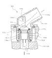
- FIG. 13 shows the thermostat device disclosed in Patent Document 1.
- This thermostat device 11 is constructed by accommodating a thermo operating unit 15 in a housing 12 composed of a case 13 and an inlet 14 .
- an inflow port 14a for the coolant from the radiator side is formed on the side of the case 13, which also constitutes the housing 12.
- an inflow port 13a for the coolant from the bypass passage bypassing the radiator On the side of the case 13, which also constitutes the housing 12, there are an inflow port 13a for the coolant from the bypass passage bypassing the radiator, and an inflow port 13b for the coolant via the heater core as a heat exchanger for heating the passenger compartment. is formed.
- the cooling liquid from the respective inlets 13a, 13b, and 14a is mixed in the housing 12 and sent out toward the water jacket of the engine through the cooling liquid outlet 13c.
- thermo operation unit 15 includes a thermo element (temperature sensing part) 15a containing a thermal expansion body (wax) that reacts to the temperature of the cooling liquid, a piston 15b that expands and contracts by the action of the thermal expansion body, and a thermo element 15a.
- a disk-shaped control valve (valve body) 15c is attached, and a spring member 15d is provided to bring the control valve 15c into contact with the inlet 14 side and bias it to the closed state.
- the tip of the piston 15b is mounted on a shaft support portion 14b formed in the inlet 14, and the open state of the control valve 15c is controlled according to the temperature of the coolant applied to the thermoelement 15a. be done. As a result, the inflow of coolant from the radiator side in particular is adjusted, and the temperature of the coolant applied to the engine is maintained at an appropriate level.
- thermo-element 15a controls the opening state of the control valve 15c depending on the temperature of the coolant from the bypass passage, thereby providing excellent temperature sensitivity corresponding to the temperature of the coolant from the engine. It is stated that it is possible to provide a thermostat device comprising:
- the present invention has been made in view of the above-mentioned technical problems of the conventional thermostat device.
- the main object is to provide a thermostat device with correspondingly good temperature sensitivity.
- a thermostat device which has been made to solve the above-described problems, comprises a first inlet for introducing coolant cooled by a radiator, and an internal combustion engine that does not pass through the radiator. a second inlet for introducing heated coolant; and a coolant outlet for supplying a mixture of the coolants from the first inlet and the second inlet to the internal combustion engine. a thermoelement housed in the housing and moving in the axial direction depending on the temperature of the cooling liquid from the second inlet; and the first inlet moving along with the movement of the thermoelement.
- thermo-element a control valve that controls the amount of coolant introduced from the a plurality of guide bodies for axially movably supporting the thermo-element; and cooling liquid rectifying claws arranged around the thermo-element at a position avoiding the guide body with a gap from the thermo-element. , the cooling liquid flowing from the second inlet side to the outlet formed between the adjacent guide bodies and the cooling liquid regulating claws, between the guide bodies, or between the cooling liquid rectifying claws.
- a detour passage is provided.
- thermo-element a plurality of guides are provided along the periphery of the thermo element forming the thermo operation unit on the side of the second inlet through which the coolant heated in the internal combustion engine is introduced without passing through the radiator.
- a body is intermittently arranged, and the thermo-element is axially movably supported by the guide body.
- thermo-element between the guide bodies that support the thermo-element, a cooling liquid regulating claw is provided with a gap from the thermo-element. According to this coolant regulating claw, part of the coolant from the second inlet can flow along the thermo-element between the coolant rectifying claw and the thermo-element. Therefore, the thermo-element can efficiently respond to the temperature of the cooling liquid from the second inlet and can control the opening and closing of the control valve, which can contribute to improving the temperature sensitivity of the thermo-actuating unit.
- a gap is formed between the guide body and the cooling liquid regulating claw, between the guide body and the guide body, or between the cooling liquid rectifying claws and the cooling liquid rectifying claw, which are arranged along the circumference.
- the thermo-element is formed in a cylindrical shape, and the guide bodies are arranged at at least three points along the circumference of the thermo-element. is arranged in sliding contact with the side surface of the thermo-element, and the length dimension along the axial direction of the thermo-element in each of the guide bodies is formed larger than the length dimension of the cooling liquid rectifying claw. be done.
- the length dimension along the axial direction of the thermo-element in each of the guide bodies is formed to be larger than the length dimension of the cooling liquid rectifying claws.
- a range of movement on the bottom side of the element can be covered. Therefore, the guide body can effectively prevent the radial deflection of the thermo-element moving in the axial direction, particularly near the bottom portion, so that the thermo-element can move smoothly in the axial direction.
- the end portion of each of the guide bodies on the second inlet side is located closer to the second inlet side than the coolant regulating claw. and a coolant flow path extending from the second inlet side to the outlet is formed between the guide bodies in a state in which the thermo-element is most moved toward the second inlet side. desirable.
- the cooling liquid flow path from the second inlet side to the outlet is formed between the guide bodies. It is formed. This flow path allows a low flow rate of coolant to flow from the second inlet to the outlet even when the thermo-element moves downward from the bottom of the case when the control valve is wide open. of cooling liquid can be secured.
- the coolant regulating claws are arranged along the axial direction of the thermoelement.
- the cooling liquid rectifying claws are arranged along the axial direction of the thermo-element, so that the cooling liquid rectifying claws direct the flow of the cooling liquid along the longitudinal direction of the cooling liquid rectifying claws. , to provide effective contact with the thermo-element. This can contribute to providing a thermostat device having excellent temperature sensitivity corresponding to the coolant temperature.
- thermoelectric device that can ensure a sufficient flow rate of coolant from the bypass passage and that has excellent temperature sensitivity corresponding to the temperature of the coolant from the engine.
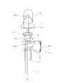
- FIG. 1 is a front view showing the overall configuration of a thermostat device according to the invention.
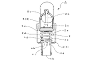
- FIG. 2 is a partial cross-sectional view showing the front half of the housing in FIG. 1.
- FIG. 3 is a partial cross-sectional view of the right half of the housing cut away and viewed from the broken direction.
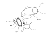
- FIG. 4 is a perspective view showing the overall configuration of the thermostat device.
- FIG. 5 is a perspective view showing a state in which the top and bottom are reversed from the state shown in FIG.
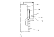
- FIG. 6 is a plan view of the second inlet side viewed from the central portion of the housing.
- FIG. 7 is a partially enlarged view showing the relationship between the second inlet and the thermo-element.
- FIG. 8 is a schematic diagram showing a state in the middle of assembling the thermostat device.
- FIG. 9 is a partially enlarged view of the state seen from the assembly jig side shown in FIG.
- FIG. 10 is an enlarged view of part A in the schematic diagram shown in FIG.
- FIG. 11 is a partially enlarged view showing the flow of coolant through the coolant bypass passage.
- FIG. 12 is a partially enlarged view showing the flow of the cooling liquid by the cooling liquid regulating claws.
- FIG. 13 is a sectional view showing an example of a conventional thermostat device.
- thermostat device according to the present invention will be described based on the embodiment shown in the drawings. 1 to 5 show the overall configuration of a thermostat device, and this thermostat device 1 is arranged in a circulation flow path for circulating coolant between an engine and a radiator to provide cooling to the engine.
- a thermo operating unit 2 for controlling liquid temperature is housed in a housing 3 .
- the thermostat device 1 is arranged at the intersection of the cooling water passage from the radiator side and the bypass passage from the engine outlet side that does not pass through the radiator, and is configured to It acts to properly control the coolant temperature to the engine inlet by mixing with the coolant from the engine inlet.
- the housing 3 forming the outer shell of the thermostat device 1 is composed of a case 4 both made of a resin material and an inlet 5 joined to the upper part of the case 4 and attached.
- the inlet 5 is provided with a cylindrically formed first inlet 5a for receiving cooling liquid from the radiator side. It is formed in a state of being bent about 10 degrees (see FIG. 3).
- a unit accommodating space 4a for the thermo-operation unit 2 is formed in the central portion, and a cylindrical second inlet 4b is formed downward from the unit accommodating space 4a. The cooling liquid from the bypass passage is introduced into the second inlet 4b.
- case 4 is formed with a coolant outlet 4c for supplying the coolant to the engine side in a direction perpendicular to the movement axis of the thermo-operation unit 2.
- 4c is formed toward the side opposite to the bending direction of the first inlet 5a formed in the inlet 5 (see FIG. 3).
- the coolant outflow port 4c is configured so that it can be arranged upstream of a water pump that feeds the coolant into the engine. 4d and an insertion hole 4e (see FIGS. 4 and 5) for a fastening bolt is formed at a position opposed to the flange 4d by 180 degrees. An annular packing 4f is attached along the opening so as to surround the outflow port 4c of the cooling liquid and is joined to the water pump side.
- the thermo-operation unit 2 housed in the unit housing space 4a of the housing 3 has a cylindrical thermo-element (temperature-sensing part) 2a containing a thermal expansion body (wax) that expands and contracts depending on the temperature of the cooling liquid. is provided, and due to expansion and contraction of the thermal expansion body, the piston 2b arranged along the axis of the thermo-element 2a operates to extend and retract from the thermo-element 2a.
- the tip portion of the piston 2b is fitted in a shaft support portion 5b formed in an upper center portion of an inlet 5 that constitutes the housing 3, and is mounted inside the housing 3. As shown in FIG. Therefore, the cylindrical thermo-element 2a moves axially within the unit housing space 4a as the piston 2b expands and contracts.
- a disk-shaped control valve (valve body) 2c is attached to the upper portion of the thermo-element 2a, and this control valve 2c contacts an annular valve seat 5c formed in the lower opening of the inlet 5. , the valve is closed.
- a spring member 2d is arranged so as to surround the thermo-element 2a so that one end thereof is in contact with the control valve 2c. It abuts on the inner bottom portion 4j (see FIGS. 6 and 7) of the case 4 so as to surround the guide body 4g and the cooling liquid regulating claw 4h. Therefore, the spring member 2d provides a biasing force to press the disk-shaped control valve 2c against the annular valve seat 5c formed in the inlet 5. As shown in FIG.
- the guide body 4g and the cooling liquid regulating claw 4h are raised from the second inlet 4b side of the case 4 toward the unit housing space 4a. formed.
- the guide body 4g is formed extending from the side of the second inlet 4b toward the thermo-element 2a. It is That is, the axially long inner contact surfaces of the three guide bodies 4g are in sliding contact with the side surfaces of the thermo-element 2a, thereby functioning to support the thermo-element 2a so as to be axially movable.
- the upper end of the guide body 4g is positioned higher than the upper end of the coolant regulating claw 4h. Furthermore, as shown in FIG. 7, the guide body 4g covers the movement range of the lower bottom side of the thermo-element 2a so as to extend from the inner bottom 4j of the case to the second inlet 4b side. is formed as Thereby, the length dimension along the axial direction of the thermo-element 2a in each of the guide bodies 4g is formed to be larger than the length dimension of the coolant regulating claw 4h.
- the guide body 4g effectively prevents radial deflection of the axially moving thermo-element 2a, particularly in the vicinity of the lower bottom, thereby allowing the thermo-element 2a to move smoothly in the axial direction. is realized.
- the cooling liquid regulating claws 4h are arranged at regular intervals in the circumferential direction between the three guide bodies 4g. That is, as shown in FIG. 7, the three cooling liquid rectifying claws 4h rise from the inner bottom portion 4j of the case, and the upper end portion thereof is formed to be slightly lower than the upper end portion of the guide body 4g. there is
- the cooling liquid regulating claw 4h is arranged with a predetermined gap from the side surface of the thermo-element 2a.
- the gap between the side surface of the thermo-element 2a and the coolant regulating claw 4h is preferably set to 1 mm or more.
- a gap portion 4i is formed in the upper portion of the inner bottom portion 4j of the case 4 between the guide body 4g and the coolant regulating claw 4h.
- the gap 4i functions as a coolant bypass passage (indicated by the same reference numeral 4i as the gap) from the second inlet 4b side to the coolant outlet 4c. The effects of the coolant bypass passage 4i will be described later.
- the ends of the guide bodies 4g on the side of the second inlet 4b are located closer to the second inlet 4b than the cooling liquid regulating claws 4h, and the control valve 2c is opened.
- the thermo-element 2a moves downward from the inner bottom portion 4j of the case due to the increased amount, as shown in FIG. is formed.
- the control valve 2c is wide open, the flow rate of the arcuate flow path 4k is low from the second inlet 4b toward the cooling liquid outlet.
- the cooling liquid can flow, and the supply amount of the cooling liquid to the engine can be secured.
- FIG. 8 to 10 show the procedure for assembling the thermostat device 1 described above.
- a support member for the thermoelement formed in a column shape is prepared as an assembly jig 7.
- the assembling jig 7 is based on an equilateral triangular prism, and the ridge lines forming the three inner corners of the equilateral prism are formed into arcuate surfaces. is as shown in FIG.
- Each arc-shaped surface is formed to have a dimension to be in contact with the second inlet 4b of the case 4 and the coolant regulating claw 4h as shown in FIG.
- the assembly jig 7 is formed with a shaft hole 7a along its axis, and at its upper end, as shown in a partially enlarged view of FIG. 10 (corresponding to part A in FIG. 8) , a small protrusion 7b is formed to protrude from the arc-shaped end face.
- the arc-shaped small projection 7b is configured to contact the bottom peripheral surface of the thermo-element 2a so that the thermo-element 2a can be placed on the upper end portion of the assembly jig 7. As shown in FIG.
- the column-shaped assembly jig 7 is inserted from the second inlet 4b side of the case 4 as shown in FIG.
- the guide body 4g formed in the case 4 is positioned so that the prismatic surface 7c of the assembly jig 7 is positioned, that is, the arc surface of the assembly jig 7 is positioned on the guide body 4g.
- the assembling jig 7 is inserted into the second inlet 4b so as not to hit it.
- the spring member 2 d is attached along the periphery of the assembly jig 7 projecting upward from the case 4 .
- thermo-element 2a to which the control valve 2c is attached in advance, is put on the upper part of the spring member 2d and pressed in the axial direction, so that the lower bottom portion of the thermo-element 2a is axially moved by using the small projection 7b as a guide as shown in FIG. The lower bottom portion thereof abuts on the upper end portion of the assembly jig 7 .
- the thermo-element 2a is attracted to the upper end portion of the assembly jig 7 and temporarily fixed.
- thermo-element 2 a With the thermo-element 2 a temporarily fixed to the upper end of the assembly jig 7 , the tip of the piston 2 b provided on the thermo-element 2 a is inserted into the shaft support portion 5 b of the inlet 5 .
- the thermo-element 2a By pulling out the assembly jig 7 from the second inlet 4b while pushing the inlet 5 toward the case 4 in this state, the thermo-element 2a is moved to the central portion of the annularly arranged guide body 4g and the cooling liquid regulating claws 4h. are housed in Finally, by joining the inlet 5 onto the case 4, the assembly of the thermostat device 1 is completed.
- the center of the thermo-element 2a is aligned with the center of the guide body 4g and the cooling liquid regulating claws 4h arranged so as to surround the second inlet 4b, and the thermo-element 2a is moved to the guide body 4g in a centered state. , can be pulled into the inside of the coolant regulating claw 4h.
- the spring member 2d does not fall during assembly, and the thermo-element 2a can always be inserted inside the guide member 4g and the coolant regulating claw 4h. In this way, the spring member 2d is prevented from collapsing, and the thermo-element 2a can always be inserted inside the guide member 4g and the cooling liquid regulating claw 4h, so assembly by an automatic machine becomes possible.
- the procedure for assembling the thermostat device 1 is not limited to this, and can be changed as appropriate.
- the thermostat device 1 may of course be manually assembled.
- the shape of the pipeline on the side of the bypass passage where the second inlet 4b is formed may of course be straight as shown in the figure, or may be L-shaped or other shapes. Even if there is, the assembly of the thermostat device 1 is possible. That is, the shape of the pipeline on the side of the bypass passage where the second inlet 4b is formed may be straight, L-shaped, or any other shape.
- the coolant supplied to the second inlet 4b from the bypass passage side is supplied into the unit accommodating space 4a of the housing 3 where the thermoelement 2a is located. Therefore, when the temperature of the cooling liquid from the bypass passage side rises, the thermal expansion body built in the thermo-element 2a expands and the piston 2b extends (protrudes). As a result, the control valve 2c attached to the thermo-element 2a is opened by retracting toward the second inlet 4b against the biasing force of the spring member 2d. Coolant is introduced through the radiator.
- the coolant from the first inlet 5a and the coolant from the second inlet 4b are mixed in the vicinity of the unit housing space 4a and sent to the water jacket of the engine from the coolant outlet 4c. Thereby, the temperature of the coolant passing through the water jacket of the engine can be controlled to an appropriate state.
- the thermostat device 1 described above has three guide bodies 4g arranged at equal intervals along the periphery of the thermoelement 2a so that the thermoelement 2a is axially moved. supported so that it can be moved to As a result, the thermo-element 2a can move smoothly along the axial direction, and the reliability of the operation of the thermo-operation unit 2 can be ensured.
- thermo-element 2a can efficiently respond to the temperature of the cooling liquid from the second inlet 4b to control the opening and closing of the control valve 2c, thereby improving the temperature sensitivity of the thermo-operation unit 2. can contribute.
- a gap is formed between the guide body 4g arranged along the periphery of the thermo-element 2a and the cooling liquid regulating claw 4h, so that the cooling liquid flows from the second inlet 4b. 12, the coolant from the second inlet 4b is diverted by the bypass passage 4i formed by the gap. can flow efficiently. Therefore, the cooling liquid from the second inlet 4b is added to the flow indicated by the arrow B in FIG. 11 and the flow indicated by the arrow C in FIG. It becomes possible to provide a thermostat device 1 that can be secured.
- three guide bodies 4g are provided at equal intervals along the circumferential direction. Unequal intervals can also be provided. Furthermore, the cooling liquid regulating claws 4h are arranged between the respective guide bodies 4g. The number can also be selectively set according to the Therefore, depending on the arrangement of the guide body 4g and the cooling liquid regulating claw 4h, the gap 4i forming the bypass passage for the cooling liquid is divided between the adjacent guide body 4g and the cooling liquid rectifying claw 4h. It may be formed between each other or between the cooling liquid regulating claws 4h.
- the thermostat device according to the present invention is useful as a device for supplying coolant to an automobile engine, and is particularly suitable for controlling the temperature of the coolant to be supplied to the engine to an appropriate state. .
Landscapes
- Engineering & Computer Science (AREA)
- General Engineering & Computer Science (AREA)
- Mechanical Engineering (AREA)
- Chemical & Material Sciences (AREA)
- Combustion & Propulsion (AREA)
- Physics & Mathematics (AREA)
- General Physics & Mathematics (AREA)
- Automation & Control Theory (AREA)
- Temperature-Responsive Valves (AREA)
- Control Of Temperature (AREA)
Abstract
Description
また冷却液温度が高くなった場合は、制御バルブが開くことで冷却液はラジエータを通して循環される。これにより、エンジン内の冷却水路であるウォータジャケット内を通る冷却液の温度を適正な状態に制御するように動作する。
この特許文献1に示されたサーモスタット装置が図13に示されており、このサーモスタット装置11はケース13とインレット14により構成されたハウジング12内に、サーモ動作ユニット15が収容されて構成される。
そして、前記ピストン15bの先端部は、前記したインレット14内に形成されたシャフト支持部14bに装着されて、サーモエレメント15aに加わる冷却液の温度に応じて、制御バルブ15cの開弁状態が制御される。これにより特にラジエータ側からの冷却液の流入量が調整され、エンジンに加わる冷却液温度を適正に保つように動作する。
この構成によると、サーモエレメント15aはバイパス通路からの冷却液温度に依存して、制御バルブ15cの開弁状態を制御することになり、エンジンからの冷却液温度に対応した優れた感温性を有するサーモスタット装置を提供することができると記載されている。
このために、前記したサーモエレメント15aと円筒体16との間の隙間において、冷却液の流れが絞られるために、ラジエータを迂回するバイパス通路からの流量が多い場合に、その流量を確保することが難しいという技術的な課題があった。
これにより、第2流入口からの冷却液の流量を十分に確保し得るサーモスタット装置を提供することが可能となる。
したがって、ガイド体は、軸方向に移動するサーモエレメントの特に下底部付近の径方向の振れを効果的に防止し、サーモエレメントの軸方向に沿った円滑な移動動作を実現させることができる。
この流路は、サーモエレメントがケース内底部より下方へ移動した制御バルブの大開口時においても、第2流入口側から流出口に向かって低流量の冷却液を流すことができるので、エンジンへの冷却液の供給量を確保することができる。
これにより、冷却液温度に対応した優れた感温性を有するサーモスタット装置を提供することに寄与できる。
前記インレット5には、ラジエータ側からの冷却液を受ける円筒状に形成された第1流入口5aが備えられ、この第1流入口5aは後述するサーモ動作ユニット2の移動軸線に対して、60度程度屈曲(図3参照)された状態で形成されている。
また、ケース4には、中央部にサーモ動作ユニット2のユニット収容空間4aが形成されると共に、そのユニット収容空間4aから下向きに、円筒状の第2流入口4bが形成されており、この第2流入口4bに、バイパス通路からの冷却液が導入される。
前記ピストン2bの先端部は、ハウジング3を構成するインレット5内の中央上部に形成されたシャフト支持部5bに嵌め込まれて、ハウジング3内に取り付けられている。
したがって、円筒状のサーモエレメント2aは、ピストン2bの伸縮に伴って、ユニット収容空間4a内を軸方向に移動するように動作する。
したがって、前記したばね部材2dは、インレット5に形成された環状の弁座5cに対して、円板状の制御バルブ2cを押し当てるように付勢力を与えている。
このうち、ガイド体4gは、第2流入口4b側からサーモエレメント2aに向かって延出して形成されており、この実施の形態においては、サーモエレメント2aの周囲に沿って、120度間隔をもって配置されている。すなわち、3本のガイド体4gにおける軸方向に長い内接面が、サーモエレメント2aの側面に摺接して、サーモエレメント2aを軸方向に移動可能に支持する機能を果たしている。
これにより、前記各ガイド体4gにおけるサーモエレメント2aの軸方向に沿った長さ寸法は、前記冷却液整流爪4hの長さ寸法に対して大きく形成されている。
そして、前記したガイド体4gは、軸方向に移動するサーモエレメント2aの特に下底部付近の径方向の振れを効果的に防止し、これにより、サーモエレメント2aの軸方向に沿った円滑な移動動作を実現させている。
そして、冷却液整流爪4hは、サーモエレメント2aの側面に対して、所定の隙間をもって配置されている。なお、サーモエレメント2aの側面と冷却液整流爪4hとの隙間は、1mm以上となるように設定されていることが望ましい。
これにより、各冷却液整流爪4hは、第2流入口4bからの冷却液の流れを、冷却液整流爪4hの長手方向に沿わせて、サーモエレメント2aに効果的に接触させる作用を与える。
この円弧状の流路4kは、サーモエレメント2aがケース内底部4jより下方へ移動した制御バルブ2cの大開口時においても、第2流入口4b側から冷却液の流出口に向かって低流量の冷却液を流すことができ、エンジンへの冷却液の供給量を確保することができる。
この組み立て治具7は、正三角柱を基本として、正三角柱の3つの内角部を形成する稜線部分を、それぞれ円弧面に成形した構成にされており、その長手方向の下端部側から見た形状は、図9に示したとおりとなる。そして、各円弧状に成形された面が、図8に示すようにケース4の第2流入口4b、及び、冷却液整流爪4hに接する寸法となるように成形されている。
この状態でインレット5をケース4側に押しつつ、組み立て治具7を第2流入口4bから引き抜くことで、サーモエレメント2aは、環状に配列されたガイド体4gと冷却液整流爪4hの中央部に収容される。
最後に、ケース4の上に、インレット5を接合することで、サーモスタット装置1の組み立てが完了する。
これにより、組み立て時にばね部材2dに倒れが生じず、必ず、サーモエレメント2aをガイド体4g、冷却液整流爪4hの内側に挿入することができる。
このように、ばね部材2dの倒れを防いで、サーモエレメント2aを必ずガイド体4g、冷却液整流爪4hの内側に挿入できるので、自動機械による組み付けが可能となる。
つまり、第2流入口4bが形成されるバイパス通路側の管路の形状は、ストレート形状、L字状、又はその他の形状であっても良い。
これにより、サーモエレメント2aに取り付けられた制御バルブ2cは、ばね部材2dの付勢力に抵抗して、第2流入口4b側に向けて後退することで開弁し、第1流入口5aからのラジエータを介した冷却液が導入される。
したがって、第1流入口5aからの冷却液と、第2流入口4bからの冷却液は、ユニット収容空間4a付近で混合されて、冷却液の流出口4cからエンジンのウォータジャケットに送り込まれる。これにより、エンジンのウォータジャケットを通る冷却液の温度を適正な状態に制御することができる。
したがって、サーモエレメント2aは、第2流入口4bからの冷却液温度に効率良く反応して、制御バルブ2cの開閉制御を行うことが可能となり、サーモ動作ユニット2の感温性を向上させることに寄与することができる。
したがって、第2流入口4bからの冷却液は、図11に矢印Bで示す流れに、図12に矢印Cで示す流れが加わることになり、バイパス通路を経由する冷却液の流量を、十分に確保し得るサーモスタット装置1を提供することが可能となる。
さらに、冷却液整流爪4hは、各ガイド体4gの間にそれぞれ配置されているが、これは各ガイド体4gの間に2本以上配置することも、また、冷却液の流出口4cの位置に応じて、その数を選択的に設定することもできる。
したがって、冷却液の迂回通路を形成する空隙部4iは、ガイド体4gと冷却液整流爪4hの配列状況に応じて、隣接するガイド体4gと冷却液整流爪4hとの間、前記ガイド体4g同士の間、又は前記冷却液整流爪4h同士の間に形成される場合もある。
2 サーモ動作ユニット
2a サーモエレメント
2b ピストン
2c 制御バルブ(弁体)
2d ばね部材
3 ハウジング
4 ケース
4a ユニット収容空間
4b 第2流入口
4c 冷却液の流出口
4d フランジ
4e ボルト挿通孔
4f パッキン
4g ガイド体
4h 冷却液整流爪
4i 空隙部(冷却液の迂回通路)
4j ケース内底部
4k 流路
5 インレット
5a 第1流入口
5b シャフト支持部
5c 弁座
Claims (4)
- ラジエータによって冷却された冷却液を導入する第1流入口と、前記ラジエータを介さない内燃機関において加熱された冷却液を導入する第2流入口と、前記第1流入口と前記第2流入口からの各冷却液を混合した冷却液を前記内燃機関に供給する冷却液の流出口とを備えたハウジングと、
前記ハウジング内に収容され、前記第2流入口からの冷却液の温度に依存して、軸方向に移動するサーモエレメントと、
前記サーモエレメントの移動に伴って、前記第1流入口からの冷却液の導入量を制御する制御バルブと、
前記第2流入口側から前記サーモエレメントに向かって延出して形成されると共に、前記サーモエレメントの周囲に沿って間欠的に配置されて、前記サーモエレメントを軸方向に移動可能に支持する複数のガイド体と、
前記サーモエレメントの周囲であって前記ガイド体を避けた位置に前記サーモエレメントと隙間を開けて配置される冷却液整流爪と、
隣接する前記ガイド体と前記冷却液整流爪との間、前記ガイド体同士の間、又は前記冷却液整流爪同士の間に形成された前記第2流入口側から前記流出口へ向かう冷却液の迂回通路と、
を備えた、
ことを特徴とするサーモスタット装置。 - 前記サーモエレメントは円筒状に形成され、前記サーモエレメントの周囲に沿った少なくとも3か所において前記ガイド体が前記サーモエレメントの側面に摺接した状態で配置されると共に、前記各ガイド体における前記サーモエレメントの軸方向に沿った長さ寸法は、前記冷却液整流爪の長さ寸法に対して大きく形成されている、
ことを特徴とする請求項1に記載のサーモスタット装置。 - 前記各ガイド体の前記第2流入口側の端部は、前記冷却液整流爪よりも前記第2流入口側に位置し、前記サーモエレメントが前記第2流入口側に最も移動した状態において、前記各ガイド体の間に、前記第2流入口側から前記流出口に至る冷却液の流路が形成される、
ことを特徴とする請求項1に記載のサーモスタット装置。 - 前記冷却液整流爪は、前記サーモエレメントの軸方向に沿って配置される、
ことを特徴とする請求項1ないし3のいずれか1項に記載のサーモスタット装置。
Priority Applications (5)
| Application Number | Priority Date | Filing Date | Title |
|---|---|---|---|
| CA3208751A CA3208751A1 (en) | 2021-02-17 | 2022-02-16 | Thermostat device |
| EP22756188.3A EP4296483A1 (en) | 2021-02-17 | 2022-02-16 | Thermostat device |
| AU2022224178A AU2022224178A1 (en) | 2021-02-17 | 2022-02-16 | Thermostat device |
| CN202280015074.5A CN116940749A (zh) | 2021-02-17 | 2022-02-16 | 恒温装置 |
| US18/274,336 US11965454B2 (en) | 2021-02-17 | 2022-02-16 | Thermostat device |
Applications Claiming Priority (2)
| Application Number | Priority Date | Filing Date | Title |
|---|---|---|---|
| JP2021-023600 | 2021-02-17 | ||
| JP2021023600A JP7332643B2 (ja) | 2021-02-17 | 2021-02-17 | サーモスタット装置 |
Publications (1)
| Publication Number | Publication Date |
|---|---|
| WO2022176870A1 true WO2022176870A1 (ja) | 2022-08-25 |
Family
ID=82931773
Family Applications (1)
| Application Number | Title | Priority Date | Filing Date |
|---|---|---|---|
| PCT/JP2022/006040 WO2022176870A1 (ja) | 2021-02-17 | 2022-02-16 | サーモスタット装置 |
Country Status (7)
| Country | Link |
|---|---|
| US (1) | US11965454B2 (ja) |
| EP (1) | EP4296483A1 (ja) |
| JP (1) | JP7332643B2 (ja) |
| CN (1) | CN116940749A (ja) |
| AU (1) | AU2022224178A1 (ja) |
| CA (1) | CA3208751A1 (ja) |
| WO (1) | WO2022176870A1 (ja) |
Citations (4)
| Publication number | Priority date | Publication date | Assignee | Title |
|---|---|---|---|---|
| WO2007108273A1 (ja) * | 2006-03-17 | 2007-09-27 | Fuji Bellows Co., Ltd. | サーモスタット装置 |
| WO2009028539A1 (ja) * | 2007-08-28 | 2009-03-05 | Toyota Jidosha Kabushiki Kaisha | 車両の冷却装置 |
| JP2011208532A (ja) * | 2010-03-29 | 2011-10-20 | Fuji Seiko Kk | サーモスタット装置 |
| JP2012026341A (ja) * | 2010-07-22 | 2012-02-09 | Aisin Seiki Co Ltd | 流体制御弁 |
Family Cites Families (5)
| Publication number | Priority date | Publication date | Assignee | Title |
|---|---|---|---|---|
| JP4683007B2 (ja) * | 2007-04-03 | 2011-05-11 | 株式会社デンソー | 四方弁および車両用蓄熱システム |
| FR2955167B1 (fr) * | 2010-01-13 | 2012-02-10 | Mark Iv Systemes Moteurs Sa | Dispositif de vanne a tiroir et circuit comprenant une telle vanne |
| DE102010032345B4 (de) * | 2010-07-27 | 2012-05-24 | Hydrometer Gmbh | Brandschutzventil und Gaszähler |
| JP5936868B2 (ja) * | 2012-01-31 | 2016-06-22 | 日本サーモスタット株式会社 | サーモスタット装置 |
| WO2018097811A1 (en) * | 2016-11-22 | 2018-05-31 | Kirpart Otomoti̇v Parçalari Sanayi̇ Ve Ti̇caret A.Ş. | Thermostat assembly with tandem thermal actuator |
-
2021
- 2021-02-17 JP JP2021023600A patent/JP7332643B2/ja active Active
-
2022
- 2022-02-16 AU AU2022224178A patent/AU2022224178A1/en active Pending
- 2022-02-16 CA CA3208751A patent/CA3208751A1/en active Pending
- 2022-02-16 EP EP22756188.3A patent/EP4296483A1/en active Pending
- 2022-02-16 US US18/274,336 patent/US11965454B2/en active Active
- 2022-02-16 CN CN202280015074.5A patent/CN116940749A/zh active Pending
- 2022-02-16 WO PCT/JP2022/006040 patent/WO2022176870A1/ja active Application Filing
Patent Citations (4)
| Publication number | Priority date | Publication date | Assignee | Title |
|---|---|---|---|---|
| WO2007108273A1 (ja) * | 2006-03-17 | 2007-09-27 | Fuji Bellows Co., Ltd. | サーモスタット装置 |
| WO2009028539A1 (ja) * | 2007-08-28 | 2009-03-05 | Toyota Jidosha Kabushiki Kaisha | 車両の冷却装置 |
| JP2011208532A (ja) * | 2010-03-29 | 2011-10-20 | Fuji Seiko Kk | サーモスタット装置 |
| JP2012026341A (ja) * | 2010-07-22 | 2012-02-09 | Aisin Seiki Co Ltd | 流体制御弁 |
Also Published As
| Publication number | Publication date |
|---|---|
| EP4296483A1 (en) | 2023-12-27 |
| US20240093630A1 (en) | 2024-03-21 |
| JP2022125803A (ja) | 2022-08-29 |
| CA3208751A1 (en) | 2022-08-25 |
| US11965454B2 (en) | 2024-04-23 |
| JP7332643B2 (ja) | 2023-08-23 |
| CN116940749A (zh) | 2023-10-24 |
| AU2022224178A1 (en) | 2023-08-17 |
Similar Documents
| Publication | Publication Date | Title |
|---|---|---|
| US6401670B2 (en) | Device for regulating the temperature of oil | |
| JP4412368B2 (ja) | 車両の冷却装置 | |
| US6592046B2 (en) | Thermostat device | |
| US5738276A (en) | Valve | |
| JP4498636B2 (ja) | サーモスタット装置 | |
| WO2022176870A1 (ja) | サーモスタット装置 | |
| JPH09112715A (ja) | 流量制御弁 | |
| TWI826674B (zh) | 恆溫器裝置 | |
| JP5114376B2 (ja) | サーモスタット装置 | |
| JP7350669B2 (ja) | 冷却水温度制御装置 | |
| WO2022176872A1 (ja) | サーモスタット装置 | |
| WO2022176871A1 (ja) | サーモスタット装置 | |
| JP7171453B2 (ja) | サーモバルブ一体型のオイルクーラまたはオイルウォーマ | |
| JP4223137B2 (ja) | サーモスタット装置 | |
| JP2004132242A (ja) | エンジン冷却水制御弁 | |
| JP2004278589A (ja) | 弁機構 | |
| JP2005127361A (ja) | サーモスタット装置 | |
| JP2017003054A (ja) | 流体制御弁及び温水加熱装置 |
Legal Events
| Date | Code | Title | Description |
|---|---|---|---|
| 121 | Ep: the epo has been informed by wipo that ep was designated in this application |
Ref document number: 22756188 Country of ref document: EP Kind code of ref document: A1 |
|
| WWE | Wipo information: entry into national phase |
Ref document number: 18274336 Country of ref document: US |
|
| WWE | Wipo information: entry into national phase |
Ref document number: 202280015074.5 Country of ref document: CN |
|
| WWE | Wipo information: entry into national phase |
Ref document number: 3208751 Country of ref document: CA |
|
| ENP | Entry into the national phase |
Ref document number: 2022224178 Country of ref document: AU Date of ref document: 20220216 Kind code of ref document: A |
|
| WWE | Wipo information: entry into national phase |
Ref document number: 2022756188 Country of ref document: EP |
|
| NENP | Non-entry into the national phase |
Ref country code: DE |
|
| ENP | Entry into the national phase |
Ref document number: 2022756188 Country of ref document: EP Effective date: 20230918 |