WO2022176794A1 - ステータ - Google Patents
ステータ Download PDFInfo
- Publication number
- WO2022176794A1 WO2022176794A1 PCT/JP2022/005574 JP2022005574W WO2022176794A1 WO 2022176794 A1 WO2022176794 A1 WO 2022176794A1 JP 2022005574 W JP2022005574 W JP 2022005574W WO 2022176794 A1 WO2022176794 A1 WO 2022176794A1
- Authority
- WO
- WIPO (PCT)
- Prior art keywords
- stator
- slot
- coil
- core
- insulating resin
- Prior art date
- Legal status (The legal status is an assumption and is not a legal conclusion. Google has not performed a legal analysis and makes no representation as to the accuracy of the status listed.)
- Ceased
Links
Images





Classifications
-
- H—ELECTRICITY
- H02—GENERATION; CONVERSION OR DISTRIBUTION OF ELECTRIC POWER
- H02K—DYNAMO-ELECTRIC MACHINES
- H02K3/00—Details of windings
- H02K3/30—Windings characterised by the insulating material
-
- H—ELECTRICITY
- H02—GENERATION; CONVERSION OR DISTRIBUTION OF ELECTRIC POWER
- H02K—DYNAMO-ELECTRIC MACHINES
- H02K1/00—Details of the magnetic circuit
- H02K1/06—Details of the magnetic circuit characterised by the shape, form or construction
- H02K1/12—Stationary parts of the magnetic circuit
- H02K1/16—Stator cores with slots for windings
-
- H—ELECTRICITY
- H02—GENERATION; CONVERSION OR DISTRIBUTION OF ELECTRIC POWER
- H02K—DYNAMO-ELECTRIC MACHINES
- H02K3/00—Details of windings
- H02K3/32—Windings characterised by the shape, form or construction of the insulation
- H02K3/34—Windings characterised by the shape, form or construction of the insulation between conductors or between conductor and core, e.g. slot insulation
- H02K3/345—Windings characterised by the shape, form or construction of the insulation between conductors or between conductor and core, e.g. slot insulation between conductor and core, e.g. slot insulation
Definitions
- the present disclosure relates to stators.
- Patent Documents 1 and 2 disclose stators. This stator has a coil fixed to a stator core via insulating paper.
- an object of the present disclosure is to provide a technique capable of improving the heat dissipation of the coil.
- the stator of the present disclosure is comprising a stator core and a coil
- the stator core has an annular yoke portion and a plurality of annularly arranged tooth portions, each of the teeth protrudes from the yoke,
- the coil has a winding that passes through the slot and is wound around the teeth,
- the winding comprises a core wire forming a conductive path and a covering portion covering the core wire, In the slot, the insulating resin is continuously filled between the inner wall of the tooth portion and the covering portion.
- FIG. 1 is a perspective view of the stator core of the first embodiment.
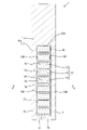
- FIG. FIG. 2 is a cross-sectional view around a coil arranged in a slot.
- FIG. 3 is a cross-sectional view taken along line AA in FIG.
- FIG. 4 is an explanatory diagram illustrating that the stator core of the first embodiment can increase the maximum torque of the motor.
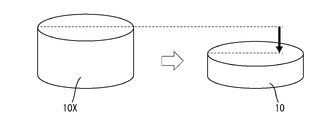
- FIG. 5 is an explanatory diagram illustrating that the stator core stack thickness of the stator core of the first embodiment can be reduced.
- FIG. 6 is an explanatory diagram explaining that the cross-sectional area of the core wire can be reduced by the stator core of the first embodiment.
- FIG. 7 is an explanatory diagram explaining that the stator core of the first embodiment can increase the effective magnetic flux.
- a stator core and a coil are provided, and the stator core has an annular yoke portion and a plurality of annularly arranged tooth portions.
- the winding includes a core wire forming a conductive path and a covering portion covering the core wire, and the insulating resin is continuously applied within the slot between the inner wall of the tooth portion and the covering portion. is filled with the stator.
- the insulating resin is continuously filled between the inner wall of the tooth portion and the covering portion in the slot without the interposition of the insulating paper. , the heat dissipation of the coil can be improved.
- the insulating resin is continuously filled in the configuration extending from the upper end side to the lower end side of the tooth portion, so that the heat dissipation can be further improved. Moreover, the state in which the coil is fixed within the slot can be further stabilized.
- the insulation between the coil and the stator core can be ensured more reliably.
- the insulation between the coil and the stator core can be ensured more reliably, and the thickness of the covering portion can be easily suppressed, so the core wire can be made thicker. Therefore, it is easy to improve the performance of the motor.
- the stator 1 of the first embodiment is used as a part of a rotating electric machine (specifically, a motor).
- the stator 1 includes a stator core 10, coils 30, and insulating resin 50, as shown in FIG.
- the radial direction of the stator 1 is called the radial direction
- the axial direction of the stator 1 is called the axial direction
- the circumferential direction of the stator 1 is called the circumferential direction.
- the stator core 10 has a yoke portion 11 and teeth portions 12, as shown in FIG.
- the yoke portion 11 has an annular shape, more specifically an annular shape.
- a plurality of teeth portions 12 are provided in a ring along the inner peripheral surface of the yoke portion 11 .
- Each tooth portion 12 is spaced apart from each other in the circumferential direction.
- Each tooth portion 12 protrudes radially inward from the inner peripheral surface of the yoke portion 11 .
- Each tooth portion 12 has a wall shape along the radial direction and the axial direction.
- Each tooth portion 12 has a wall-shaped tooth body 13 along the radial direction and the axial direction, and an overhang projecting from the tip portion (in other words, the radially inner end portion) of the tooth body 13 to both sides in the circumferential direction. a portion 14;
- the stator core 10 may be, for example, a laminated steel plate manufactured by laminating a plurality of electromagnetic steel plates (for example, silicon steel plates) in the thickness direction, or may be a compacted powder formed by press-molding magnetic particles coated with insulation. It may be a magnetic core.
- two adjacent tooth portions 12 form a slot 20.
- the slots 20 are defined by the tooth portions 12 on both sides in the circumferential direction, and by the yoke portions 11 on the radial outer surface.
- the slots 20 are open on both axial and radial inner surfaces of the stator 1 .
- the coil 30 may be distributed winding or concentrated winding.
- the coil 30 has a wire 31 that passes through the slot 20 and is wound around the teeth 12, as shown in FIG.
- the winding 31 includes a core wire 32 forming a conductive path and a covering portion 33 covering the core wire 32 .
- the core wire 32 is a conductor.
- the covering portion 33 forms an insulating layer.
- the material of the covering portion 33 is not particularly limited.
- the covering portion 33 is a low dielectric constant enamel having a low dielectric constant in this embodiment.
- the covering portion 33 is mainly composed of a thermosetting resin such as polyvinyl formal, thermosetting polyurethane, thermosetting acrylic, epoxy, thermosetting polyester, thermosetting polyesterimide, aromatic polyamide, thermosetting polyamideimide, and thermosetting polyimide. good too.
- the covering portion 33 may be made mainly of a thermoplastic resin such as polyetherimide, polyphenylene ether, polyether sulfone, polyphenylene sulfide, polyether ether ketone, or thermoplastic polyimide.
- the "main component” is the component with the largest content, for example, a component containing 50% by mass or more.
- the slot 20 is filled with an insulating resin 50 .
- a filling method is not particularly limited.
- the filling method is, for example, transfer molding.
- the type of insulating resin is not particularly limited. Types of insulating resin include, for example, epoxy resin, PBT resin, PET resin, PPS resin, SPS resin, m-PPE resin, nylon resin (PA6, PA46, PA66), aromatic nylon resin (PA4T, PA6T, PA9T, PA10T ), LCP resin and the like are preferred.
- the insulating resin 50 is continuously filled in the slot 20 between the inner wall 12A of the tooth portion 12 and the covering portion 33 of the winding 31.
- the insulating resin 50 is continuously filled between the inner wall 12A of the tooth portion 12 and the covering portion 33 in the slots 20 without the interposition of insulating paper. Therefore, the stator 1 can improve heat dissipation of the coil 30 as compared with a configuration in which insulating paper is interposed. For example, when varnish is impregnated into insulating paper, an air layer is likely to occur, and as a result, the heat dissipation tends to decrease.
- the winding 31 has a plurality of insertion portions 34 arranged in the same slot 20 .
- the insertion portion 34 includes the core wire 32 and the covering portion 33 described above.
- the plurality of insertion portions 34 are arranged side by side in the radial direction.
- the insulating resin 50 is also continuously filled between two insertion portions 34 arranged adjacent to each other in the same slot 20 . For this reason, it is easy to improve heat dissipation even between two insertion portions 34 that are arranged adjacent to each other in the same slot 20 .
- the insulating resin 50 is continuously filled with the insulating resin 50 so as to extend from the upper end portion 12B side to the lower end portion 12C side of the tooth portion 12 . Therefore, the stator 1 can further improve heat dissipation. Moreover, the state in which the coil 30 is fixed within the slot 20 can be further stabilized.
- the inner wall 20A of the slot 20 is spaced apart from the windings 31 throughout. Therefore, the stator 1 can ensure the insulation between the coils 30 and the stator core 10 more reliably.
- the covering portion 33 is made of low dielectric constant enamel. Therefore, in the stator 1, the insulation between the coils 30 and the stator core 10 can be ensured more reliably, and the thickness of the covering portion 33 can be easily reduced, so that the core wire 32 can be easily thickened. That is, the space factor, which is the ratio of the core wires 32 occupying the slot 20, can be improved. Therefore, it is easy to improve the performance (for example, torque) of the motor. Moreover, insulation can be ensured only by the covering portion 33 . In other words, the insulating resin 50 can be continuously filled into the slot 20 to improve the heat dissipation, and the insulating property can be ensured by the covering portion 33 of the low dielectric constant enamel.
- the insulating resin 50 is continuously filled between the inner wall 12A of the tooth portion 12 and the covering portion 33 in the slot 20 without an insulating paper interposed therebetween. can be improved.
- the covering portion 33 is made of low dielectric constant enamel.
- insulation can be ensured by the winding 31 alone.
- the insulating paper is removed and the slots 20 are continuously filled with the insulating resin 50 to improve the heat dissipation, while the low dielectric constant enamel covering portion 33 enhances the insulating property. can be guaranteed.
- the core wire 32 When current flows through the coil 30, the core wire 32 generates heat.
- the upper limit of the current flowing through the core wire 32 is determined based on the upper limit of the allowable temperature range of the core wire 32 .
- heat dissipation is improved, so the upper limit of the current flowing through the core wire 32 is increased. That is, according to the stator 1 , the upper limit of the current flowing through the core wire 32 can be increased without changing the size of the stator 1 .
- the maximum torque of the motor is proportional to the current flowing through the coil 30 . Therefore, according to the stator 1, the maximum torque of the motor to which the stator 1 is applied can be increased. For example, as shown in FIG. 4, the maximum torque can be increased by the second area AR2 as compared to the first area AR1 corresponding to the stator provided with insulating paper.
- the laminated thickness (length in the axial direction) of the stator core 10 can be reduced without changing the applied maximum torque of the motor.
- the stack thickness of the stator core 10 is proportional to the maximum applied torque of the motor. That is, the thickness of the stator core 10 can be reduced without changing the maximum torque of the motor.
- the stack thickness (length in the axial direction) of the stator core 10 is reduced while maintaining the same maximum torque of the motor to be applied. be able to.
- the laminated thickness of the stator core 10 By reducing the laminated thickness of the stator core 10, the amount of material used is reduced, and as a result, the material cost is reduced.
- the stator cores 10 and 10X are schematically drawn.
- the cross-sectional area of the core wire 32 can be reduced without changing the applied maximum torque of the motor and the laminated thickness (length in the axial direction) of the stator core 10 .
- the current flowing through the core wire 32 is proportional to the cross-sectional area of the core wire 32 . That is, the cross-sectional area of the core wire 32 can be reduced without changing the current flowing through the core wire 32 (maximum torque of the motor applied) and the stack thickness (length in the axial direction) of the stator core 10 .
- the width dimension (length in the circumferential direction) of the core wire 32 can be made smaller than the core wire 32Y of the stator 1Y provided with insulating paper (not shown).
- the amount of material used for the core wire 32 can be reduced, resulting in reduced material costs. Further, even if the thickness (the length in the circumferential direction) of the teeth portion 12 is increased as shown in FIG. A lower price per unit volume reduces overall material costs.
- the effective magnetic flux 60 is increased by increasing the thickness (length in the circumferential direction) of the tooth portion 12 compared to the tooth portion 12Z where the leakage magnetic flux 61 exists.
- the maximum torque of the motor is proportional to the effective flux. Therefore, according to this configuration, the maximum torque of the motor to which the stator 1 is applied can be increased.
Landscapes
- Engineering & Computer Science (AREA)
- Power Engineering (AREA)
- Insulation, Fastening Of Motor, Generator Windings (AREA)
- Iron Core Of Rotating Electric Machines (AREA)
Priority Applications (4)
| Application Number | Priority Date | Filing Date | Title |
|---|---|---|---|
| JP2023500816A JP7468774B2 (ja) | 2021-02-18 | 2022-02-14 | ステータ |
| CN202280012328.8A CN116762260A (zh) | 2021-02-18 | 2022-02-14 | 定子 |
| US18/546,442 US12573907B2 (en) | 2021-02-18 | 2022-02-14 | Stator having slots filled with resin for insulation |
| DE112022001114.9T DE112022001114T5 (de) | 2021-02-18 | 2022-02-14 | Stator |
Applications Claiming Priority (2)
| Application Number | Priority Date | Filing Date | Title |
|---|---|---|---|
| JP2021-024027 | 2021-02-18 | ||
| JP2021024027 | 2021-02-18 |
Publications (1)
| Publication Number | Publication Date |
|---|---|
| WO2022176794A1 true WO2022176794A1 (ja) | 2022-08-25 |
Family
ID=82930577
Family Applications (1)
| Application Number | Title | Priority Date | Filing Date |
|---|---|---|---|
| PCT/JP2022/005574 Ceased WO2022176794A1 (ja) | 2021-02-18 | 2022-02-14 | ステータ |
Country Status (5)
| Country | Link |
|---|---|
| US (1) | US12573907B2 (https=) |
| JP (1) | JP7468774B2 (https=) |
| CN (1) | CN116762260A (https=) |
| DE (1) | DE112022001114T5 (https=) |
| WO (1) | WO2022176794A1 (https=) |
Families Citing this family (2)
| Publication number | Priority date | Publication date | Assignee | Title |
|---|---|---|---|---|
| US12573907B2 (en) * | 2021-02-18 | 2026-03-10 | Autonetworks Technologies, Ltd. | Stator having slots filled with resin for insulation |
| JP7695098B2 (ja) * | 2021-04-14 | 2025-06-18 | 株式会社日立産機システム | 回転電機 |
Citations (2)
| Publication number | Priority date | Publication date | Assignee | Title |
|---|---|---|---|---|
| JP2014154262A (ja) * | 2013-02-05 | 2014-08-25 | Furukawa Electric Co Ltd:The | 耐インバータサージ絶縁ワイヤ |
| JP2018107921A (ja) * | 2016-12-27 | 2018-07-05 | トヨタ自動車株式会社 | 回転電機のステータ |
Family Cites Families (9)
| Publication number | Priority date | Publication date | Assignee | Title |
|---|---|---|---|---|
| JP4998450B2 (ja) * | 2008-12-09 | 2012-08-15 | トヨタ自動車株式会社 | ステータの製造方法 |
| JP2013062911A (ja) | 2011-09-12 | 2013-04-04 | Toyota Motor Corp | モータ用の絶縁シートとステータコアにコイルを固定する方法 |
| JP2017163797A (ja) | 2016-03-11 | 2017-09-14 | 本田技研工業株式会社 | 電動機用ステータの製造方法および電動機用ステータ |
| EP3547506B1 (en) * | 2016-11-28 | 2026-03-25 | Panasonic Intellectual Property Management Co., Ltd. | Motor |
| CN110383643B (zh) * | 2017-02-28 | 2021-04-02 | 松下知识产权经营株式会社 | 模制马达 |
| JP7092617B2 (ja) | 2018-08-29 | 2022-06-28 | 日立Astemo株式会社 | 回転電機の固定子の製造方法 |
| US12573907B2 (en) * | 2021-02-18 | 2026-03-10 | Autonetworks Technologies, Ltd. | Stator having slots filled with resin for insulation |
| CN115441643A (zh) * | 2021-06-03 | 2022-12-06 | 株式会社牧田 | 电动作业机 |
| JP2022185821A (ja) * | 2021-06-03 | 2022-12-15 | 株式会社マキタ | 電動作業機 |
-
2022
- 2022-02-14 US US18/546,442 patent/US12573907B2/en active Active
- 2022-02-14 DE DE112022001114.9T patent/DE112022001114T5/de active Pending
- 2022-02-14 CN CN202280012328.8A patent/CN116762260A/zh active Pending
- 2022-02-14 JP JP2023500816A patent/JP7468774B2/ja active Active
- 2022-02-14 WO PCT/JP2022/005574 patent/WO2022176794A1/ja not_active Ceased
Patent Citations (2)
| Publication number | Priority date | Publication date | Assignee | Title |
|---|---|---|---|---|
| JP2014154262A (ja) * | 2013-02-05 | 2014-08-25 | Furukawa Electric Co Ltd:The | 耐インバータサージ絶縁ワイヤ |
| JP2018107921A (ja) * | 2016-12-27 | 2018-07-05 | トヨタ自動車株式会社 | 回転電機のステータ |
Also Published As
| Publication number | Publication date |
|---|---|
| JP7468774B2 (ja) | 2024-04-16 |
| JPWO2022176794A1 (https=) | 2022-08-25 |
| US12573907B2 (en) | 2026-03-10 |
| DE112022001114T5 (de) | 2023-12-14 |
| CN116762260A (zh) | 2023-09-15 |
| US20240186857A1 (en) | 2024-06-06 |
Similar Documents
| Publication | Publication Date | Title |
|---|---|---|
| US9893594B2 (en) | Armature of rotating electrical machine and method for manufacturing same | |
| JP5267091B2 (ja) | 回転電機用ステータ | |
| JP6299729B2 (ja) | 回転電機ステータ | |
| CN104620474B (zh) | 旋转电机的定子 | |
| JP2015033173A (ja) | モータ | |
| JP7468774B2 (ja) | ステータ | |
| CN107408859B (zh) | 轴向间隙型旋转电机和定子 | |
| JP7394396B2 (ja) | ステータ及びそれを用いたモータ | |
| JP3743480B2 (ja) | 回転機 | |
| CN111903037B (zh) | 感应电动机的转子及感应电动机 | |
| US20120256511A1 (en) | Stator | |
| CN103035463A (zh) | 具有带轭铁绕组的定子的旋转阳极的驱动装置 | |
| JP7280706B2 (ja) | 回転電機の固定子及びそれを用いた回転電機 | |
| US20240235311A1 (en) | Armature and motor | |
| JP2022175072A (ja) | モータ | |
| WO2011148501A1 (ja) | ステータ | |
| JP2005198500A (ja) | 回転機 | |
| JP5271991B2 (ja) | 回転電機の固定子 | |
| JP2023161806A (ja) | ステータ及びステータの製造方法 | |
| CN116998091A (zh) | 定子及具有定子的旋转电机 | |
| JP2014054044A (ja) | ステータ及びこのステータを備えた回転電機 | |
| JP6776850B2 (ja) | 回転電機 | |
| JP5958216B2 (ja) | 回転電機の固定子 | |
| JP2003088030A (ja) | ギャップワインディングモータ | |
| JP2023150105A (ja) | ステータ |
Legal Events
| Date | Code | Title | Description |
|---|---|---|---|
| 121 | Ep: the epo has been informed by wipo that ep was designated in this application |
Ref document number: 22754766 Country of ref document: EP Kind code of ref document: A1 |
|
| ENP | Entry into the national phase |
Ref document number: 2023500816 Country of ref document: JP Kind code of ref document: A |
|
| WWE | Wipo information: entry into national phase |
Ref document number: 202280012328.8 Country of ref document: CN |
|
| WWE | Wipo information: entry into national phase |
Ref document number: 18546442 Country of ref document: US |
|
| WWE | Wipo information: entry into national phase |
Ref document number: 112022001114 Country of ref document: DE |
|
| 122 | Ep: pct application non-entry in european phase |
Ref document number: 22754766 Country of ref document: EP Kind code of ref document: A1 |
|
| WWG | Wipo information: grant in national office |
Ref document number: 18546442 Country of ref document: US |