WO2022176702A1 - 自動分析装置 - Google Patents
自動分析装置 Download PDFInfo
- Publication number
- WO2022176702A1 WO2022176702A1 PCT/JP2022/004851 JP2022004851W WO2022176702A1 WO 2022176702 A1 WO2022176702 A1 WO 2022176702A1 JP 2022004851 W JP2022004851 W JP 2022004851W WO 2022176702 A1 WO2022176702 A1 WO 2022176702A1
- Authority
- WO
- WIPO (PCT)
- Prior art keywords
- control sequence
- unit
- liquid level
- control
- cleaning liquid
- Prior art date
- Legal status (The legal status is an assumption and is not a legal conclusion. Google has not performed a legal analysis and makes no representation as to the accuracy of the status listed.)
- Ceased
Links
Images








Classifications
-
- G—PHYSICS
- G01—MEASURING; TESTING
- G01N—INVESTIGATING OR ANALYSING MATERIALS BY DETERMINING THEIR CHEMICAL OR PHYSICAL PROPERTIES
- G01N35/00—Automatic analysis not limited to methods or materials provided for in any single one of groups G01N1/00 - G01N33/00; Handling materials therefor
- G01N35/02—Automatic analysis not limited to methods or materials provided for in any single one of groups G01N1/00 - G01N33/00; Handling materials therefor using a plurality of sample containers moved by a conveyor system past one or more treatment or analysis stations
Definitions
- the present invention relates to an automatic analyzer.
- the valve adjustment function 84 operates the first nozzle 251, the fourth nozzle 254, and the fifth nozzle according to the determination result regarding the state of the cleaning mechanism 230 determined by the determination function 82. 255 and the sixth nozzle 256.
- the control circuit 8A adjusts the absorbance change rate calculated by executing the determination function 82. For example, the amount of increase or decrease in the amount of cleaning liquid ejected from the first nozzle is calculated based on the calculated amount of increase or decrease in the amount of cleaning liquid.
- the opening time of the three-way electromagnetic valve 271 is adjusted so that the amount of cleaning liquid discharged from the first nozzle 251 is appropriate" (Paragraph 0084).
- Patent Document 1 if the adjusted amount of cleaning liquid satisfies a predetermined range condition, the adjustment process is terminated. Therefore, even if the liquid amount is adjusted to near the upper and lower limits of the range condition, the adjustment will be completed if the liquid amount is within the range condition. In this case, readjustment is required soon after the adjustment, and there is a problem that it takes time and money for the operator. In addition, there is also the problem that the analysis must be stopped frequently in order to adjust the amount of washing liquid.
- the present invention has been made in view of such problems, and its purpose is to provide an automatic analyzer that reduces the frequency of adjusting the amount of cleaning liquid in the reaction vessel.
- the present invention provides a discharge nozzle for discharging a cleaning liquid into a reaction vessel, an electromagnetic valve provided in a path for supplying the cleaning liquid to the discharge nozzle, and a liquid amount of the cleaning liquid.
- An automatic analyzer comprising a liquid level detector and a control unit for controlling the solenoid valve, wherein the control unit stores a control sequence for causing the solenoid valve to perform different operations; a determination unit for determining which of the different control sequences should be applied during analysis, and all or part of the control sequences stored in the storage unit are executed when adjusting the amount of cleaning liquid; , the liquid amount of the cleaning liquid corresponding to each control sequence is detected by the liquid amount detector, and the determination unit relatively The control sequence with a high likelihood is determined to be applied at the time of analysis.
- FIG. 1 is an overall configuration diagram of an automatic analyzer according to an embodiment; FIG. The figure which showed together the structure for washing
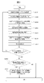
- 4 is a flow chart showing a procedure for liquid level height adjustment according to the first embodiment. A data table showing that all control sequences have been executed and the data has been updated. The graph which showed the electromagnetic valve opening time and liquid level height as an execution result of all the control sequences.
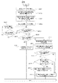
- 8 is a flowchart showing a procedure for liquid level height adjustment according to the second embodiment; A data table showing that some control sequence has been executed and the data has been updated. A graph showing solenoid valve open time and liquid level as a result of execution of some control sequences.
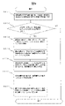
- 10 is a flowchart showing a procedure for predicting the date and time when the selected control sequence no longer satisfies the allowable range condition in the third embodiment; A data table that holds data related to the slope of the relational expression for each past liquid volume adjustment. An example of the screen that an operator sees when scheduling the start of cleaning fluid volume adjustment. 10 is a flowchart showing a procedure for predicting a date and time when all control sequences no longer satisfy the allowable range condition in the fourth embodiment; An example of the screen displayed when notifying the operator that the adjustment of the amount of cleaning fluid has been completed. 10 is a flow chart showing a procedure for a diagnosis unit to diagnose an abnormality of a solenoid valve due to a factor other than aged deterioration in the fifth embodiment; An example of an analysis result detail screen.
- FIG. 1 is an overall configuration diagram of an automatic biochemical analyzer according to this embodiment.
- the automatic analyzer includes a mechanism drive section 103 , an operation section 108 operated by an operator, and a control section 102 that controls the mechanism drive section 103 .
- the mechanism drive unit 103 includes a drive circuit 110, a sample container 111 that holds a measurement target, a sample dispensing mechanism 113 that dispenses the sample in the sample container 111 into a reaction container 112 (reaction cell), and a reaction cell.
- a reagent dispensing mechanism 114 that dispenses the reagent into the container 112, a stirring mechanism 115 that stirs the mixed solution in the reaction container 112, a photometer 116 that measures the absorbance of the mixed solution in the reaction container 112, and the measurement is completed.
- the operation unit 108 is a terminal including an input unit 119 such as a keyboard and mouse, and an output unit 120 such as a display and printer.
- the control unit 102 includes a CPU 104, a memory 121 that stores programs executed by the CPU 104, a storage unit 105 that stores a control sequence 124 that defines procedures for controlling the mechanism driving unit 103, and the mechanism driving unit 103. It has an I/O 106 that is an input/output for control, an ADC 107 that converts an analog signal to digital and takes in measurement data, and an I/F 109 that is an interface for communicating with the operation unit 108 . Note that the programs stored in the memory are conceptually divided into a determination unit 122 and a prediction unit 123 for each function.
- the storage unit 105 stores a plurality of control sequences 124 that cause the solenoid valve 205 for discharging cleaning liquid to perform different operations, specifically, a plurality of control sequences 124 with different opening times of the solenoid valve 205.
- the determination unit 122 determines which of the different control sequences 124 should be applied during analysis.
- the prediction unit 123 predicts when the control sequence 124 being applied (during selection) will no longer satisfy a predetermined condition.
- the drive circuit 110 of the mechanism drive unit 103 is controlled by a signal from the I/O 106 of the control unit 102 to operate each mechanism such as the sample dispensing mechanism 113, the reagent dispensing mechanism 114, and the stirring mechanism 115.
- the sample and the reagent are mixed in the reaction container 112 by driving.
- the photometer 116 of the mechanism drive unit 103 measures the absorbance of this mixture at a wavelength corresponding to each analysis item, and the ADC 107 takes in the measurement data to analyze the sample.
- the control unit 102 calculates the concentration of a predetermined component contained in the specimen based on the measured absorbance, and outputs the calculation result to the output unit 120 .
- the sample may be analyzed by detecting scattered light or using other measurement principles.
- the used reaction container 112 after being used for analysis is washed inside after aspirating the mixed liquid by a washing mechanism 117 arranged near the reaction disk 130, thereby enabling repeated use.
- FIG. 2 is a diagram showing both the configuration for cleaning the reaction container and the configuration for adjusting the amount of the cleaning liquid.
- the cleaning mechanism 117 includes a discharge nozzle 207 for discharging the cleaning liquid and a suction nozzle 208 for discarding the cleaning liquid.
- a channel 203 is connected to the discharge nozzle 207 as a cleaning liquid supply channel, and an electromagnetic valve 205 and a pump 204 are provided upstream of the channel 203 .
- Electromagnetic valve 205 and pump 204 are controlled by control circuit 206 to send cleaning liquid to discharge nozzle 207 through channel 203 .
- the control circuit 206 is controlled by the CPU 104 of the control unit 102 .
- the cleaning mechanism 117 cleans the inside of the reaction container 112 by supplying the cleaning liquid from the discharge nozzle 207 to the reaction container 112 arranged on the reaction disk 130 .
- the cleaning liquid in the reaction container 112 after cleaning is sucked by the suction nozzle 208 and discharged from the reaction container 112 .
- the height detector 202 detects the height of the cleaning liquid supplied to the reaction vessel 112 by the discharge nozzle 207 .
- a liquid level detector that is provided in the probe 201 of the reagent dispensing mechanism 114 and detects contact of the liquid level with the probe 201 is used.
- the drive circuit 110 is connected to the probe 201 , and the drive circuit 110 moves the probe 201 horizontally or vertically according to a signal from the CPU via the I/O 106 . Therefore, the control unit 102 positions the probe 201 in the reaction container 112 and detects the amount of movement of the probe 201 when the height detector 202 detects the liquid level of the cleaning solution in the reaction container 112, thereby detecting the cleaning solution. can be calculated.
- the invention is not limited to this as long as it has a mechanism capable of detecting the liquid level.
- the height detector 202 of the specimen dispensing mechanism 113 may be used.
- an example of using a liquid level detector as the height detector 202 is given, but it is also possible to detect the liquid level height by other methods such as image processing.
- cleaning liquid amount adjustment processing (maintenance processing) is performed in a standby state in which the automatic analyzer does not perform analysis. For example, maintenance processing is started when an operator issues an instruction to perform maintenance processing using the input unit 119 of the automatic analyzer. An example of adjusting the amount of cleaning liquid by changing the opening time of the solenoid valve 205 will be described below.
- FIG. 3 is a flow chart showing the procedure for adjusting the liquid level according to the first embodiment.
- control unit 102 selects an arbitrary (unexecuted) control sequence 124 stored in the storage unit 105 (step S301), and the selected control sequence 124 is executed up to step S307 below.
- the CPU 104 commands the I/O 106 to move the ejection nozzle 207 of the cleaning mechanism 117 from the normal standby position to the cleaning liquid ejection position.
- the drive circuit 110 receives an input from the I/O 106 and moves the ejection nozzle 207 from the normal standby position to the cleaning liquid ejection position.
- the CPU 104 controls the pump 204 and the electromagnetic valve 205 via the control circuit 206 to start discharging the washing liquid into the empty reaction vessel 112 (step S302). .
- the CPU 104 commands the I/O 106 to move the discharge nozzle 207 from the cleaning liquid discharge position to the normal standby position.
- the drive circuit 110 receives an input from the I/O 106 and raises the discharge nozzle 207 to the normal standby position.
- the CPU 104 instructs the I/O 106 to rotate the reaction disk 130 until the reaction container 112 discharged with the cleaning liquid moves to the dispensing position of the probe 201 of the reagent dispensing mechanism 114 .
- the driving circuit 110 receives an input from the I/O 106 and rotates the reaction disk 130 until the reaction vessel 112 reaches the dispensing position of the probe 201 (step S303).
- the CPU 104 commands the I/O 106 to lower the probe 201 until the height detector 202 detects the liquid level.
- Drive circuit 110 receives input from I/O 106 to lower probe 201 .
- the control unit 102 derives the liquid level of the cleaning liquid based on the amount of movement of the probe 201 until the height detector 202 detects the liquid level (step S304).
- the control unit 102 stores the derived liquid level in the data table shown in FIG. 4 in the storage unit 105 (step S305).
- This data table contains, for each control sequence 124, the opening time of the solenoid valve 205 defined in the control sequence 124, the liquid level obtained as a result of executing the control sequence 124, and the date and time when the control sequence 124 was executed. , and a selection flag indicating that the control sequence 124 is applied to the cleaning operation during analysis.
- the control unit 102 updates the liquid level height and measurement date/time data corresponding to the executed control sequence 124 in the data table to the liquid level height and measurement date/time derived above.
- the data of the control sequence 124 are arranged in ascending order of the opening time of the solenoid valve 205.
- the control sequence The arrangement order of the 124 data is not limited to this.
- the data of the control sequence 124 may be arranged in descending order of the opening time of the solenoid valve 205 .
- the CPU 104 commands the I/O 106 to rotate the reaction disk 130 until the reaction container 112 moves to the suction position of the suction nozzle 208 of the cleaning mechanism 117 .
- the drive circuit 110 receives an input from the I/O 106 and rotates the reaction disk 130 until the reaction container 112 is sucked by the suction nozzle 208 (step S306).
- control unit 102 moves the suction nozzle 208 of the cleaning mechanism 117 from the normal standby position to the cleaning liquid discharge position.
- the control unit 102 controls the pump 204 via the control circuit 206 to start sucking the cleaning liquid (step S307).
- the CPU 104 commands the I/O 106 to move the suction nozzle 208 from the cleaning liquid suction position to the normal standby position.
- the drive circuit 110 receives an input from the I/O 106 and raises the suction nozzle 208 to the normal standby position.
- each control sequence 124 may be executed sequentially by pipeline processing. In this pipeline processing, for example, while the n-th control sequence 124 is performing step S303, the n+1-th control sequence 124 simultaneously performs step S302.
- the determination unit 122 of the control unit 102 determines whether or not the derived liquid surface height of the cleaning liquid satisfies a predetermined allowable range condition. .
- the storage unit 105 of this embodiment holds an upper limit value and a lower limit value as the allowable range condition of the liquid level, and furthermore, whether or not the likelihood is relatively high within the allowable range condition is determined. It holds the reference value of the liquid level for judgment.
- the operator may set the upper limit value and the lower limit value of the allowable range condition from the input unit 119 .
- the reference value in this embodiment is the median value between the upper limit value and the lower limit value of the liquid level height, but is not limited to this.
- the reference value may be set to a value closer to the lower limit of the allowable range condition than the median value. Also, instead of the reference value, a reference range narrower than the allowable range condition described above may be set.
- the determination unit 122 determines whether or not there is liquid level height data that satisfies the allowable range condition among the updated liquid level heights in the data table (step S308).
- the control unit 102 notifies the operator via the output unit 120 that the cleaning liquid amount cannot be adjusted.
- the content of the notification to the operator includes prompting the operator to replace the electromagnetic valve 205 .
- the determination unit 122 determines the liquid level that is relatively close to the reference value of the liquid level held by the storage unit 105 .
- the height realization control sequence 124 is extracted from the data table. In this way, the determination unit 122 determines that the control sequence 124 with a relatively high likelihood among the plurality of control sequences 124 satisfying the allowable range condition should be applied at the time of analysis. A selection flag is set to ON (step S309). If there is only one data of the liquid level that satisfies the allowable range condition, the selection flag of the control sequence 124 corresponding to that data is set to ON. After that, the control unit 102 notifies the operator via the output unit 120 that the adjustment of the amount of cleaning liquid has been completed.
- the control unit 102 applies the control sequence 124 in which the selection flag is set to ON as the control sequence 124 during the cleaning operation of the reaction vessel 112 during operation (analysis), and discharges the cleaning liquid.
- the automatic analyzer of this embodiment can guarantee discharge of a specified amount of liquid when cleaning the reaction container 112, and can suppress the frequency of adjusting the amount of cleaning liquid.
- FIG. 4 is a data table showing that all control sequences 124 have been executed and the data has been updated
- FIG. It is a graph showing the degree.
- the control unit 102 of the automatic analyzer reselects the control sequence 124 to be used when cleaning the empty reaction container 112 for which measurement has been completed based on the trigger set by the operator using the input unit 119, so that maintenance processing is performed.
- the trigger set for adjustment of the amount of cleaning liquid includes a manual execution mode, an automatic execution mode based on an adjustment interval or timing pre-selected by the operator, and a mode predicted in Example 3 described later. There is a mode that automatically runs based on the time of year, and so on.
- the storage unit 105 holds six control sequences 124 as shown in FIG.
- the control unit 102 executes all of these control sequences 124 according to steps S302 to S307 shown in FIG.
- the graph in FIG. 5 shows the resulting liquid level for each control sequence 124 .
- control sequence No. 1 is to open the electromagnetic valve 205 for 0.5 seconds, and as a result of discharging the cleaning liquid, the liquid level was 8.9 mm.
- control sequence No. 2 when the solenoid valve 205 is opened for 0.6 seconds, the liquid level becomes 9.3 mm
- control sequence No. 3 when the solenoid valve 205 is opened for 0.7 seconds, the liquid level becomes 9.
- control sequence No. 4 when the solenoid valve 205 is opened for 0.8 seconds, the liquid level becomes 10.1 mm
- control sequence No. 5 when the solenoid valve 205 is opened for 0.9 seconds, the liquid level becomes was 10.4 mm
- control sequence No. 6 when the electromagnetic valve 205 was opened for 1.0 second, the liquid surface height was 10.7 mm.
- the determination unit 122 determines whether or not there is data on the liquid level that satisfies the allowable range condition, as in step S308 of FIG. 3 described above.
- the allowable range condition is 9.5 to 10.5 mm, and there are three execution results (control sequence Nos. 3 to 5) of the control sequence 124 that satisfy the allowable range condition. to step S309.
- step S309 the determination unit 122 extracts the control sequence 124 that achieves a liquid level relatively close to the above-described reference value from the three control sequences 124 that satisfy the allowable range condition.
- the reference value is the median value of 10.0 between the lower limit value of 9.5 mm and the upper limit value of 10.5 mm.
- the execution result of control sequence No. 3 is a liquid level height of 9.7 mm
- the execution result of control sequence No. 4 is a liquid level height of 10.1 mm
- the execution result of control sequence No. 3 is a liquid level height of 10.4 mm.
- Control sequence No. 4 which achieves a liquid level height of 10.1 mm, achieves a liquid level height relatively close to the reference value of 10.0 mm.
- the determination unit 122 determines the control sequence No. 4 as the control sequence 124 to be applied at the time of analysis, and turns on (1 in this embodiment) the selection flag corresponding to the control sequence No. 4 in the data table of FIG.
- the selection flags corresponding to other control sequences are set to off (0 in this embodiment).
- the liquid level is used as an adjustment index to adjust the liquid volume.
- the liquid amount may be derived from the liquid surface height and the liquid amount itself may be used as the adjustment index.
- the liquid volume can be calculated from the measured liquid level.
- the control sequence 124 closest to the reference value (relatively highly likely) is extracted.
- the second embodiment illustrates a more efficient adjustment method that requires fewer control sequences 124 to be executed than the first embodiment. In the following, explanations of parts common to the first embodiment will be omitted as appropriate.
- FIG. 6 is a flow chart showing the procedure for adjusting the liquid level according to the second embodiment.
- execution flag data for each control sequence is held in the data table held by the storage unit 105 of this embodiment.
- the execution flag is for distinguishing between the executed control sequence 124 and the non-executed control sequence 124 when adjusting the amount of cleaning liquid.
- the determination unit 122 can more efficiently select the control sequence 124 to be executed next from the unexecuted control sequences 124 whose execution flag is turned off. Note that the execution flag is set to OFF (0 in this embodiment) each time adjustment is started, and then adjustment is started.
- control unit 102 sets all execution flags and selection flags in the data table to off.
- two control sequences 124 with smaller control sequence numbers are executed (step S501). Since the control flow of steps S302 to S307 shown in FIG. 3 is defined for each control sequence 124, two control sequences 124 are executed according to this definition.
- the determination unit 122 calculates a relational expression between the opening time of the electromagnetic valve 205 and the detected liquid level based on the execution results of the two control sequences 124 (step S502). Further, the determining unit 122 uses the relational expression calculated in step S502 to determine whether the solenoid valve 205 is open, which is considered to achieve a liquid level relatively close to the reference value of the liquid level held in the storage unit 105.
- a control sequence 124 having time is extracted from the control sequences 124 whose execution flag is off (step S503).
- the control unit 102 executes the control sequence 124 extracted in step S503 (step S504), stores the execution result in the data table, and sets the execution flag of the control sequence 124 to ON.
- the determination unit 122 determines whether or not the liquid level obtained as a result of step S504 satisfies the allowable range condition held by the storage unit 105 (step S505). If it is determined in step S505 that the permissible range condition is not satisfied, the determination unit 122 determines whether or not the control sequence 124 whose execution flag is set to OFF exists in the data table (step S506). ). In step S506, if there is no control sequence 124 whose execution flag is set to OFF, the control unit 102 notifies the operator via the output unit 120 that the amount of cleaning liquid cannot be adjusted.
- control unit 102 executes one unexecuted control sequence 124 (step S507).
- step S507 an example of executing a control sequence having a relatively small control sequence No. among unexecuted control sequences is given, but the control sequence 124 to be executed is not limited to this.
- the control unit 102 not only saves the execution result of step S507 in the data table, but also sets the execution flag of the control sequence 124 to ON.
- step S505 when it is determined that the liquid level height obtained as the execution result of step S504 satisfies the allowable range condition held by the storage unit 105, the determination unit 122 It is determined whether or not the obtained liquid level height is the same as the reference value held by the storage unit 105 (step S508). In this determination, it may be determined whether or not they are the same with a certain width. For example, when the liquid level height obtained as a result of executing step S504 is a value within ⁇ 1% of the reference value, the liquid level height is determined to be the same as the reference value. good too.
- step S504 If it is determined that the liquid level height obtained as a result of executing step S504 is the same as the reference value of the liquid level held by the storage unit 105, the control unit 102 stores the data table executed in step S504. The selection flag of the data corresponding to the control sequence 124 is set to ON (step S509). After that, the control unit 102 notifies the operator via the output unit 120 that the adjustment of the amount of cleaning liquid has been completed.
- step S504 determines that the control sequence 124 executed in step S504 Check if there is a control sequence that is close to the reference value. Therefore, using the relational expression calculated in step S502, determination unit 122 determines whether the opening time of solenoid valve 205 is longer than the opening time of solenoid valve 205 defined in control sequence 124 executed in step S504. It is determined whether the length should be shortened or whether the length should be shortened (step S510).
- a specific determination method of the determination unit 122 in step S510 is that if the liquid level height obtained as a result of the execution of step S504 is lower than the reference value, the opening time of the solenoid valve 205 is lengthened and the If it is high, the opening time of the solenoid valve 205 is shortened.
- the determination unit 122 narrows down the control sequence 124 to be executed next based on the opening time of the control sequence 124 executed immediately before and based on the determination result in step S510. Then, the control unit 102 executes the control sequence 124 narrowed down by the determination unit 122 (step S511). The control unit 102 not only saves the execution result of step S511 in the data table, but also sets the execution flag of the control sequence 124 to ON.
- the determination unit 122 determines whether or not the liquid level obtained as a result of executing step S511 satisfies the allowable range condition held by the storage unit 105 (step S512). If it is determined in step S512 that the permissible range condition is not satisfied, the determining unit 122 turns on the selection flag of the data corresponding to the second last executed control sequence 124 in the data table (step S513).
- step S512 determines that the liquid level height obtained from the control sequence 124 executed second last is higher than the liquid level height obtained from the control sequence 124 executed last. 124 is relatively close to the reference value (step S514).
- the determination unit 122 sets the selection flag corresponding to the second last executed control sequence 124 to ON (1 in this embodiment), and sets the selection flags corresponding to the other control sequences to OFF (0 in this embodiment). (step S513).
- the determination unit 122 sets the selection flag corresponding to the last executed control sequence 124 to ON (1 in this embodiment), and sets the selection flags corresponding to the other control sequences to OFF (0 in this embodiment). (Step S515).
- FIG. 7 is a data table showing that part of the control sequence 124 (resulting in No, 1, 2, 4, 5) has been executed and the data has been updated
- FIG. is a graph showing the opening time of the solenoid valve 205 and the liquid level as the execution result of .
- the control unit 102 of the automatic analyzer starts maintenance processing in order to reselect the control sequence 124 to be used when cleaning the empty reaction container 112 for which measurement has been completed, based on the trigger set by the operator through the input unit 119. .
- step S501 of FIG. 6 described above the control unit 102 executes control sequence No. 1 and control sequence No. 2. As shown in FIG. 8, the result of executing the control sequence No. 1 is 10 mm, and the result of executing the control sequence No. 2 is 13 mm.
- step S502 of FIG. 6 the determination unit 122 calculates a relational expression between the opening time of the solenoid valve 205 and the liquid level obtained by executing the control sequence 124 from the execution result of step S501.
- the liquid level is 10 mm for an opening time of the solenoid valve 205 of 0.5 seconds
- the liquid level is 13 mm for an opening time of the solenoid valve 205 of 0.6 seconds.
- step S503 the reference value is 20 mm, and the determination unit 122 calculates the electromagnetic valve open time corresponding to this reference value using the above-described relational expression, resulting in approximately 0.83 seconds.
- Control sequence 124 in which the electromagnetic valve opening time relatively close to 0.83 seconds is defined is control sequence No. 4 in which the electromagnetic valve opening time is defined to be 0.8 seconds. Therefore, in step S504 of FIG. 6, control sequence No. 4 is executed, and the liquid level height obtained as a result of the execution is 19 mm.
- step S504 of FIG. 6 the determination unit 122 determines whether or not the liquid level height of 19 mm obtained as the execution result of step S504 of FIG. 6 satisfies the allowable range condition.
- the allowable range condition is 15 mm to 25 mm, and the liquid level height of 19 mm satisfies the allowable range condition, so the process proceeds to step S508 in FIG.
- step S508 of FIG. 6 the determination unit 122 determines whether or not the liquid level height of 19 mm obtained as a result of executing step S504 of FIG. 6 is the same as the reference value. As shown in FIG. 8, the reference value is 20 mm, and the liquid level height of 19 mm is not the same as the reference value.
- step S510 of FIG. 6 the determination unit 122 selects, as the control sequence 124 to be executed next, a control sequence 124 with a longer electromagnetic valve opening time than the control sequence 124 executed in step S504 of FIG. Determine whether to Here, when the liquid level height obtained as the execution result of step S504 is higher than the reference value, the determination unit 122 performs to extract On the other hand, if the liquid level obtained as a result of execution of step S504 is lower than the reference value, control sequence 124 with a longer electromagnetic valve open time than control sequence 124 executed in step S504 is extracted. Now, the liquid level height of 19 mm obtained as a result of executing step S504 is lower than the reference value of 20 mm. Therefore, the determination unit 122 extracts, as the control sequence 124 to be executed next, a control sequence 124 having a longer electromagnetic valve opening time than the control sequence 124 executed in step S504, and proceeds to step S511 in FIG.
- step S511 of FIG. 6 the determination unit 122 is relatively close to the electromagnetic valve opening time of the control sequence 124 executed in step S504 and satisfies the determination result in step S510, that is, the time executed in step S504
- the control sequence is narrowed down to those having a longer electromagnetic valve open time than the control sequence 124 .
- the determination unit 122 narrows down the control sequence No. 5 as the control sequence 124 to be executed next.
- the control unit 102 executes control sequence No. 5, and proceeds to step S512 in FIG.
- the determination unit 122 determines whether or not the liquid level height obtained as a result of executing step S511 satisfies the allowable range condition. As shown in FIG. 8, the tolerance condition is 15 mm to 25 mm. Since the liquid level height of 22 mm obtained by executing the control sequence No. 5 in step S511 satisfies the allowable range condition, the process proceeds to step S514 in FIG.
- step S514 of FIG. 6 the determination unit 122 determines that the liquid level obtained from the control sequence 124 executed last is higher than the liquid level obtained from the control sequence 124 executed second to last. , is relatively close to the reference value.
- the liquid level height obtained from the second last executed control sequence 124 (control sequence No. 4) is 19 mm
- the liquid level height obtained from the last executed control sequence 124 (control sequence No. 5) length is 22 mm.
- the reference value is 20 mm, so the second last executed control sequence 124 (control sequence No. 4) is relatively close to the reference value. Therefore, the process proceeds to step S515 in FIG.
- step S515 of FIG. 6 the determination unit 122 determines the control sequence 124 executed second to last (control sequence No. 4) as the control sequence 124 to be applied at the time of analysis, and in the data table of FIG.
- the selection flag corresponding to No. 4 is set to ON (1 in this embodiment), and the selection flag corresponding to the other control sequences is set to OFF (0 in this embodiment).
- two control sequences 124 to be executed first two control sequences 124 with relatively small control sequence Nos in the data table are used as an example, but the present invention is not limited to this.
- the control sequence 124 with the shortest opening time of the solenoid valve 205 and the control sequence 124 with the longest opening time of the solenoid valve 205 may be executed first.
- the operator may use the input unit 119 to select the two control sequences 124 to be executed first.
- the prediction unit 123 of the control unit 102 predicts the date and time when the applied (selected) control sequence 124 no longer satisfies the allowable range condition of the liquid level held in the storage unit 105. do. This allows the operator to more accurately know the date and time when the liquid level of the cleaning liquid should be readjusted according to the usage environment of the automatic analyzer.
- FIG. 9 is a flowchart showing a procedure for the prediction unit 123 to predict the date and time when the currently selected control sequence 124 no longer satisfies the allowable range condition in the third embodiment.
- the prediction unit 123 performs predicts an example.
- the timing to be predicted is not limited to this, and may be performed independently of the cleaning liquid amount adjustment process.
- the prediction unit 123 calculates the relational expression between the open time of the electromagnetic valve 205 and the detected liquid level based on the results of all or at least two control sequences 124 executed during the cleaning liquid amount adjustment process. , information such as the slope of the relational expression is stored in the data table of the storage unit 105 (step S601).
- FIG. 10 is a data table holding data on the slope of the relational expression for each past liquid volume adjustment. As shown in FIG. 10, this data table includes, for example, the slope of the relational expression calculated for each cleaning liquid amount adjustment, and the difference value between the slope and the slope at the time of the previous adjustment (the slope from the time of the previous adjustment).
- the cleaning liquid amount adjustment that is performed first includes the difference value between the slope and the slope at the time of the previous adjustment, the number of days elapsed from the date and time of the previous adjustment to the date and time of the adjustment, the amount of change in slope per day, and the predicted date and time. , are left blank.
- the prediction unit 123 determines whether or not the data table shown in FIG. 10 contains data for two or more cleaning liquid volume adjustments (step S602). If there is no cleaning liquid amount adjustment data for two or more times, the prediction unit 123 ends the process of predicting the date and time when the currently selected control sequence 124 no longer satisfies the allowable range condition of the liquid level. On the other hand, if there is data for two or more cleaning liquid volume adjustments, the prediction unit 123 acquires all the data of “slope change from previous adjustment” stored in the data table shown in FIG. A value is calculated, and whether the sign of the average value is plus or minus is calculated (step S603). Note that the data used when calculating the average value may not be all the data, but may be the latest three data or the like.
- the prediction unit 123 determines whether the liquid level height realized by the currently selected control sequence 124 will change over time to either the upper limit value or the lower limit value of the allowable range condition. It predicts whether it will approach (step S604). Specifically, when the calculation result in step S603 is positive, it indicates that the slope of the relational expression between the solenoid valve open time and the liquid level height increases with age. is predicted to approach the upper limit value. On the other hand, if the calculation result in step S603 is negative, it indicates that the slope of the relational expression between the solenoid valve open time and the liquid level decreases with age. It is predicted that the liquid level achieved by 124 will approach the lower limit.
- the prediction unit 123 calculates a relational expression (limit relation Equation) is calculated (step S605).
- the relational expression between the solenoid valve opening time and the liquid level approximates a proportional relational expression, so the prediction unit 123 corresponds to the currently selected control sequence 124 from the boundary value predicted in step S604.
- the slope of the limit relational expression can be calculated by dividing the electromagnetic valve opening time.
- the prediction unit 123 calculates the period required for the slope of the relational expression saved in the data table in step S601 to reach the slope of the limit relational expression calculated in step S605 (S606). Specifically, first, the prediction unit 123 acquires all the data of the “amount of tilt change per day” stored in the data table shown in FIG. 10, and calculates the average value thereof. It should be noted that the data used when calculating the average value may not be all the data, but may be the latest three data or the like. Next, the prediction unit 123 subtracts the slope of the relational expression stored in step S601 from the slope of the limit relational expression calculated in step S605.
- the prediction unit 123 divides the difference obtained as a result of the subtraction by the average value, so that the slope of the relational expression saved in the data table in step S601 becomes the slope of the limit relational expression calculated in step S605. It is possible to calculate the period required to reach the target.
- the prediction unit 123 adds the period obtained in step S606 to the current date and time, and uses the calculation result as the predicted date and time when the selected control sequence 124 no longer satisfies the allowable range condition for the liquid level height. Save in the table (step S607).
- control unit 102 sets the predicted date and time in step S607 as shown in (1) of FIG. , are displayed on the output unit 120 as candidates for the next adjustment date and time.
- control unit 102 displays the predicted date and time of step S607 as shown in FIG. It can be so. For example, when the operator selects "Manual” in FIG. 11 and operates the Set button, adjustment of the amount of cleaning liquid is immediately executed. On the other hand, when the operator selects "Auto” in FIG. 11, selects "Recommendation”, and operates the Set button, the amount of cleaning liquid is automatically adjusted at the predicted date and time in step S607. Further, when the operator selects "Auto” in FIG. 11, selects "Regular interval” and operates the Set button, the cleaning liquid amount is automatically adjusted at intervals specified by the operator. Note that the control unit 102 may notify via the output unit 120 if the predicted date and time in step S607 is reached before the period specified by the operator is reached.
- the predicted date and time in step S607 are displayed in the input unit 119 as they are, but the predicted date and time displayed in the input unit 119 are not limited to this.
- the control unit 102 may display, on the input unit 119, the date and time 30 days before the predicted date and time in step S607. Further, for example, the control unit 102 may display on the input unit 119 from 30 days before the predicted date and time in step S607 prompting the operator to readjust the cleaning liquid amount.
- the cleaning liquid amount may be adjusted according to the schedule set by the operator from the input unit 119, but the operator's setting is not necessarily required.
- an automatic analyzer may perform adjustment at a predetermined timing such as before each analysis.
- the prediction unit 123 of the control unit 102 predicts the date and time when all the control sequences 124 held in the storage unit 105 by the automatic analysis control device no longer satisfy the allowable range condition of the liquid level. do. This allows the operator to more accurately know the date and time when the electromagnetic valve 205 should be replaced according to the usage environment of the automatic analyzer.
- FIG. 12 is a flowchart showing a procedure for the prediction unit 123 to predict the date and time when all the control sequences 124 held by the automatic analysis control device no longer satisfy the allowable range conditions in the fourth embodiment.
- the prediction unit 123 makes a prediction immediately before the output unit 120 outputs a notification to the operator that the cleaning liquid amount adjustment process has been completed.
- the timing for prediction is not limited to this, and may be performed independently of the cleaning liquid amount adjustment process, or may be performed together with the third embodiment.
- the prediction unit 123 calculates the relational expression between the open time of the electromagnetic valve 205 and the detected liquid level based on the results of all or at least two control sequences 124 executed during the cleaning liquid amount adjustment process. , information such as the slope of the relational expression is stored in the data table of the storage unit 105 (step S901).
- the slope of the relational expression calculated for each cleaning liquid amount adjustment and the difference value between the slope and the slope at the time of the previous adjustment change in slope
- the adjustment date and time when the cleaning liquid amount adjustment was performed the number of days elapsed from the previous adjustment date and time to the adjustment date and time
- the slope change amount per day and the predicted date and time.
- the predicted date and time in this embodiment is the date and time when all the control sequences 124 held in the storage unit 105 are predicted to no longer satisfy the allowable range condition.
- the prediction unit 123 determines whether or not the data table contains data for two or more cleaning liquid volume adjustments (step S902). If there is no cleaning liquid amount adjustment data for two or more times, the prediction unit 123 ends the process of predicting the date and time when all the control sequences 124 no longer satisfy the allowable range condition of the liquid level. On the other hand, if there is data for two or more cleaning liquid volume adjustments, the prediction unit 123 acquires all the data of the “slope change from the previous adjustment” saved in the data table, and calculates the average value. , whether the sign of the average value is plus or minus is calculated (step S903).
- the prediction unit 123 uses the calculation result of step S903 to determine whether the liquid level height realized by the control sequence 124 approaches the upper limit value or the lower limit value of the allowable range condition with aging. is predicted (step S904).
- step S904 when it is predicted that the liquid level achieved by the control sequence 124 will approach the lower limit with age, the prediction unit 123 , the relational expression between the solenoid valve opening time and the liquid level (lower limit relational expression ) is calculated (step S905).
- step S904 when it is predicted that the liquid level height realized by the control sequence 124 will approach the upper limit with age, the prediction unit 123 predicts the control sequence 124 held by the automatic analyzer. Among them, the relational expression between the solenoid valve opening time and the liquid level (upper limit relational expression) is calculated (step S906).
- the prediction unit 123 calculates the period required for the slope of the relational expression stored in the data table in step S901 to reach the slope of the lower limit relational expression or upper limit relational expression calculated in step S905 or step S906 (step S907). Specifically, first, the prediction unit 123 acquires all the data of the “amount of tilt change per day” stored in the data table, and calculates the average value thereof. Next, the prediction unit 123 subtracts the slope of the relational expression stored in step S901 from the slope of the lower limit relational expression or the upper limit relational expression calculated in step S905 or step S906.
- the prediction unit 123 divides the difference obtained as a result of the subtraction by the average value, so that the slope of the relational expression stored in the data table in step S901 becomes the lower limit relational expression calculated in step S905 or S906.
- the period required to reach the slope of the upper limit relational expression can be calculated.
- the prediction unit 123 adds the period obtained in step S907 to the current date and time, and determines that all the control sequences 124 held by the automatic analysis control device satisfy the permissible range condition of the liquid level height. It is saved in the data table as the predicted date and time when it will disappear (step S908).
- control unit 102 sets the predicted date and time in step S908 as shown in (2) of FIG. , the date and time when the solenoid valve 205 should be replaced is displayed on the output unit 120 .
- the fifth embodiment exemplifies a method of diagnosing whether or not the electromagnetic valve 205 has an abnormality due to a factor other than deterioration over time.
- Factors other than aging deterioration include, for example, clogging with dust. This allows the operator to detect an abnormality in the solenoid valve 205 before the solenoid valve 205 fails and becomes unusable.
- FIG. 14 is a flow chart showing the procedure for the diagnosis unit to diagnose an abnormality of the solenoid valve 205 due to factors other than aged deterioration in the fifth embodiment.
- the diagnosis unit performs diagnosis immediately before the output unit 120 outputs a notification to the effect that the cleaning liquid amount adjustment process has been completed to the operator.
- the timing of diagnosis is not limited to this, and may be performed independently of the cleaning liquid amount adjustment processing, or may be performed together with the third or fourth embodiment.
- the diagnostic unit calculates a relational expression between the open time of the solenoid valve 205 and the detected liquid level, Information such as the slope of the relational expression and the amount of change in the slope is stored in the data table of the storage unit 105 (step S1101).
- the data table of this embodiment includes, for each cleaning liquid amount adjustment, the calculated slope of the relational expression, the difference value between the slope and the slope at the previous adjustment (slope change from the previous adjustment), and the cleaning liquid amount It holds the adjustment date and time when the adjustment was performed, the number of days elapsed from the previous adjustment date and time to the adjustment date and time, the inclination change amount per day, and the abnormality diagnosis result.
- the diagnosis unit determines whether or not there is data for two or more washing liquid volume adjustments in the data table (step S1102). If there is no cleaning liquid amount adjustment data for two or more times, the diagnosis unit terminates the abnormality diagnosis process. On the other hand, if there is data for adjusting the amount of cleaning liquid for two or more times, the diagnosis unit acquires all the data of the "slope change amount per day" saved in the data table and calculates the average value (step S1103). Note that the data used when calculating the average value may not be all the data, but may be the latest three data or the like.
- the diagnosis unit calculates the degree of divergence from the average value of the "slope change amount per day” saved in the data table in step S1101 and the "slope change amount per day” calculated in step S1103, and the ratio. (step S1104).
- the method for calculating the degree of divergence is not limited to this, and for example, the average value calculated in step S1103 is subtracted from the "slope change amount per day" saved in step S1101 to calculate the degree of divergence as an absolute value. You may
- the diagnosis unit diagnoses whether the degree of divergence calculated in step S1104 falls within the allowable range condition held by the storage unit 105 (step S1105).
- the storage unit 105 holds the permissible range conditions in the form of percentages for the diagnosis of step S1105, and the diagnosis unit uses them for diagnosis.
- the allowable range conditions held by the storage unit 105 may be held in the form of real numbers.
- step S1105 if the degree of divergence falls within the allowable range condition, the diagnosis unit sets the abnormality diagnosis result data corresponding to the cleaning liquid amount adjustment to "no abnormality" in the data table held by the storage unit 105. is set and saved (step S1106). On the other hand, in step S1105, if the degree of divergence does not fall within the allowable range condition, the diagnosis unit stores the data of the abnormality diagnosis result corresponding to the cleaning liquid volume adjustment in the data table held by the storage unit 105 as "abnormality”. "Yes” is set and saved (step S1107).
- control unit 102 outputs the abnormality diagnosis result of step S1106 or step S1107 to (3) of FIG. is displayed in accordance with the output unit 120 as shown in .
- Example 6 when the control unit 102 uses a different control sequence 124 for analysis according to the usage status of the automatic analyzer, the used control sequence 124 and the analysis result are stored in the storage unit 105 in association with each other. be. After the analysis is completed, the automatic analyzer of the present embodiment displays the type of control sequence 124 applied at the time of analysis on the output unit 120 together with the analysis result. As a result, the automatic analyzer of this embodiment can ensure traceability even when different control sequences 124 are used depending on the situation.
- FIG. 15 is a detailed screen of analysis results output by the control unit 102 to the output unit 120.
- FIG. The storage unit 105 holds the control sequence 124 used during analysis for each analysis operation, and the control unit 102 outputs the corresponding relationship to the output unit 120 as shown in (1) of FIG. .
- a case where the storage unit 105 holds the data table shown in FIG. 7 will be described below.
- the control sequence No. 4 in FIG. 7 is used as the control sequence for the cleaning operation when cleaning the reaction container 112 used for analysis, 'Washing' in (1) 'Sequence Details' in FIG. Operation) corresponds to control sequence No. 4.
- the control sequences held in the data table of FIG. 7 differ in the opening time of the solenoid valve 205 respectively.
- an example of an automatic biochemical analyzer has been described, but the present invention is not limited to this, and can also be applied to an automatic immune analyzer, an automatic coagulation analyzer, and the like.
- a height detector for detecting the height of the liquid surface was used as the liquid level detector, but the liquid level of the cleaning liquid may be detected by other methods.
- the amount of liquid is adjusted by changing the opening time of the solenoid valve, but the amount of liquid may be adjusted by other methods such as changing the degree of opening of the solenoid valve.
Landscapes
- Physics & Mathematics (AREA)
- Health & Medical Sciences (AREA)
- Life Sciences & Earth Sciences (AREA)
- Chemical & Material Sciences (AREA)
- Analytical Chemistry (AREA)
- Biochemistry (AREA)
- General Health & Medical Sciences (AREA)
- General Physics & Mathematics (AREA)
- Immunology (AREA)
- Pathology (AREA)
- Automatic Analysis And Handling Materials Therefor (AREA)
Priority Applications (2)
| Application Number | Priority Date | Filing Date | Title |
|---|---|---|---|
| JP2023500761A JP7516648B2 (ja) | 2021-02-22 | 2022-02-08 | 自動分析装置 |
| JP2024107290A JP7787243B2 (ja) | 2021-02-22 | 2024-07-03 | 自動分析装置、および、自動分析装置による分析方法 |
Applications Claiming Priority (2)
| Application Number | Priority Date | Filing Date | Title |
|---|---|---|---|
| JP2021026169 | 2021-02-22 | ||
| JP2021-026169 | 2021-02-22 |
Publications (1)
| Publication Number | Publication Date |
|---|---|
| WO2022176702A1 true WO2022176702A1 (ja) | 2022-08-25 |
Family
ID=82930485
Family Applications (1)
| Application Number | Title | Priority Date | Filing Date |
|---|---|---|---|
| PCT/JP2022/004851 Ceased WO2022176702A1 (ja) | 2021-02-22 | 2022-02-08 | 自動分析装置 |
Country Status (2)
| Country | Link |
|---|---|
| JP (2) | JP7516648B2 (https=) |
| WO (1) | WO2022176702A1 (https=) |
Citations (5)
| Publication number | Priority date | Publication date | Assignee | Title |
|---|---|---|---|---|
| JP2010085097A (ja) * | 2008-09-29 | 2010-04-15 | Olympus Corp | 分析装置およびプローブ洗浄方法 |
| JP2010122177A (ja) * | 2008-11-21 | 2010-06-03 | Beckman Coulter Inc | 自動分析装置および洗剤ポンプ異常判定方法 |
| JP2016090345A (ja) * | 2014-10-31 | 2016-05-23 | 株式会社東芝 | 臨床検査装置 |
| JP2017106791A (ja) * | 2015-12-09 | 2017-06-15 | 株式会社日立ハイテクノロジーズ | 自動分析装置及び自動分析装置の異常判定方法 |
| JP2018048820A (ja) * | 2016-09-20 | 2018-03-29 | キヤノンメディカルシステムズ株式会社 | 自動分析装置 |
Family Cites Families (2)
| Publication number | Priority date | Publication date | Assignee | Title |
|---|---|---|---|---|
| JP2007315949A (ja) | 2006-05-26 | 2007-12-06 | Toshiba Corp | 自動分析装置 |
| JP5366689B2 (ja) | 2009-07-16 | 2013-12-11 | 株式会社東芝 | 自動分析装置 |
-
2022
- 2022-02-08 JP JP2023500761A patent/JP7516648B2/ja active Active
- 2022-02-08 WO PCT/JP2022/004851 patent/WO2022176702A1/ja not_active Ceased
-
2024
- 2024-07-03 JP JP2024107290A patent/JP7787243B2/ja active Active
Patent Citations (5)
| Publication number | Priority date | Publication date | Assignee | Title |
|---|---|---|---|---|
| JP2010085097A (ja) * | 2008-09-29 | 2010-04-15 | Olympus Corp | 分析装置およびプローブ洗浄方法 |
| JP2010122177A (ja) * | 2008-11-21 | 2010-06-03 | Beckman Coulter Inc | 自動分析装置および洗剤ポンプ異常判定方法 |
| JP2016090345A (ja) * | 2014-10-31 | 2016-05-23 | 株式会社東芝 | 臨床検査装置 |
| JP2017106791A (ja) * | 2015-12-09 | 2017-06-15 | 株式会社日立ハイテクノロジーズ | 自動分析装置及び自動分析装置の異常判定方法 |
| JP2018048820A (ja) * | 2016-09-20 | 2018-03-29 | キヤノンメディカルシステムズ株式会社 | 自動分析装置 |
Also Published As
| Publication number | Publication date |
|---|---|
| JP7787243B2 (ja) | 2025-12-16 |
| JP7516648B2 (ja) | 2024-07-16 |
| JP2024127942A (ja) | 2024-09-20 |
| JPWO2022176702A1 (https=) | 2022-08-25 |
Similar Documents
| Publication | Publication Date | Title |
|---|---|---|
| JP7399330B2 (ja) | 自動分析装置、及びその洗浄方法 | |
| JP5761753B2 (ja) | 自動分析装置及びその動作不良判定方法 | |
| US9897622B2 (en) | Automatic analyzer | |
| JP7455142B2 (ja) | 自動分析装置 | |
| EP2876449A1 (en) | Automatic analysis device | |
| JP6660844B2 (ja) | 自動分析装置及びプログラム | |
| JPWO2015019880A1 (ja) | 自動分析装置 | |
| EP3872496B1 (en) | Automated analyzer | |
| US11828765B2 (en) | Automatic analysis apparatus and method of controlling automatic analysis apparatus | |
| JP2017106791A (ja) | 自動分析装置及び自動分析装置の異常判定方法 | |
| WO2022176702A1 (ja) | 自動分析装置 | |
| US12360077B2 (en) | Automatic analysis device and automatic analysis method of specimen | |
| JP2013217740A (ja) | 自動分析装置 | |
| EP4350358A1 (en) | Automatic analysis device | |
| JP6333550B2 (ja) | 自動分析装置 | |
| JP2015215367A (ja) | 自動分析装置 | |
| JP7560647B2 (ja) | 自動分析システム及び検体分配方法 | |
| WO2022196157A1 (ja) | 自動分析装置およびその流路確認方法 | |
| JP7139171B2 (ja) | 自動分析装置 | |
| JP7817108B2 (ja) | 自動分析装置および洗浄液量の調整方法 | |
| JP2011047838A (ja) | 自動分析装置 | |
| JP2024027707A (ja) | 自動分析装置 | |
| JP2013120161A (ja) | 自動分析装置 | |
| JP5215164B2 (ja) | 自動分析装置及び自動分析装置における手分注測定方法 | |
| JPWO2020066523A1 (ja) | 自動分析装置 |
Legal Events
| Date | Code | Title | Description |
|---|---|---|---|
| 121 | Ep: the epo has been informed by wipo that ep was designated in this application |
Ref document number: 22756023 Country of ref document: EP Kind code of ref document: A1 |
|
| ENP | Entry into the national phase |
Ref document number: 2023500761 Country of ref document: JP Kind code of ref document: A |
|
| NENP | Non-entry into the national phase |
Ref country code: DE |
|
| 122 | Ep: pct application non-entry in european phase |
Ref document number: 22756023 Country of ref document: EP Kind code of ref document: A1 |