WO2022176600A1 - 採血装置及び採血方法 - Google Patents
採血装置及び採血方法 Download PDFInfo
- Publication number
- WO2022176600A1 WO2022176600A1 PCT/JP2022/003795 JP2022003795W WO2022176600A1 WO 2022176600 A1 WO2022176600 A1 WO 2022176600A1 JP 2022003795 W JP2022003795 W JP 2022003795W WO 2022176600 A1 WO2022176600 A1 WO 2022176600A1
- Authority
- WO
- WIPO (PCT)
- Prior art keywords
- blood
- blood collection
- collected
- flow rate
- volume
- Prior art date
Links
- 239000008280 blood Substances 0.000 title claims abstract description 492
- 210000004369 blood Anatomy 0.000 title claims abstract description 492
- 238000000034 method Methods 0.000 title claims abstract description 28
- 230000017531 blood circulation Effects 0.000 claims abstract description 101
- 230000007423 decrease Effects 0.000 claims abstract description 99
- 230000008859 change Effects 0.000 claims description 54
- 210000004204 blood vessel Anatomy 0.000 claims description 22
- 230000003247 decreasing effect Effects 0.000 claims description 17
- 230000009467 reduction Effects 0.000 claims description 11
- 230000000694 effects Effects 0.000 claims description 9
- 230000036770 blood supply Effects 0.000 claims description 8
- 230000023555 blood coagulation Effects 0.000 claims description 7
- 208000012266 Needlestick injury Diseases 0.000 claims description 5
- 238000011084 recovery Methods 0.000 claims description 4
- 230000004308 accommodation Effects 0.000 abstract 2
- 238000010241 blood sampling Methods 0.000 description 36
- 230000008569 process Effects 0.000 description 10
- 238000012544 monitoring process Methods 0.000 description 9
- 230000005856 abnormality Effects 0.000 description 7
- 238000010586 diagram Methods 0.000 description 7
- 238000001514 detection method Methods 0.000 description 6
- 238000012545 processing Methods 0.000 description 6
- 230000007704 transition Effects 0.000 description 6
- 208000007536 Thrombosis Diseases 0.000 description 5
- 230000007246 mechanism Effects 0.000 description 5
- 238000005452 bending Methods 0.000 description 3
- 230000010485 coping Effects 0.000 description 3
- 230000006866 deterioration Effects 0.000 description 3
- 230000000903 blocking effect Effects 0.000 description 2
- 238000012790 confirmation Methods 0.000 description 2
- 238000005259 measurement Methods 0.000 description 2
- 238000007789 sealing Methods 0.000 description 2
- 102000003712 Complement factor B Human genes 0.000 description 1
- 108090000056 Complement factor B Proteins 0.000 description 1
- 230000009471 action Effects 0.000 description 1
- 230000002776 aggregation Effects 0.000 description 1
- 238000004220 aggregation Methods 0.000 description 1
- 239000003146 anticoagulant agent Substances 0.000 description 1
- 229940127219 anticoagulant drug Drugs 0.000 description 1
- 239000010836 blood and blood product Substances 0.000 description 1
- 229940125691 blood product Drugs 0.000 description 1
- 230000036760 body temperature Effects 0.000 description 1
- 239000012141 concentrate Substances 0.000 description 1
- 238000009472 formulation Methods 0.000 description 1
- 230000005484 gravity Effects 0.000 description 1
- 239000004973 liquid crystal related substance Substances 0.000 description 1
- 239000000203 mixture Substances 0.000 description 1
- 238000012986 modification Methods 0.000 description 1
- 230000004048 modification Effects 0.000 description 1
- 230000002093 peripheral effect Effects 0.000 description 1
- 238000012805 post-processing Methods 0.000 description 1
- 238000002360 preparation method Methods 0.000 description 1
- 210000002784 stomach Anatomy 0.000 description 1
- 231100000331 toxic Toxicity 0.000 description 1
- 230000002588 toxic effect Effects 0.000 description 1
- 210000003462 vein Anatomy 0.000 description 1
Images


Classifications
-
- A—HUMAN NECESSITIES
- A61—MEDICAL OR VETERINARY SCIENCE; HYGIENE
- A61M—DEVICES FOR INTRODUCING MEDIA INTO, OR ONTO, THE BODY; DEVICES FOR TRANSDUCING BODY MEDIA OR FOR TAKING MEDIA FROM THE BODY; DEVICES FOR PRODUCING OR ENDING SLEEP OR STUPOR
- A61M1/00—Suction or pumping devices for medical purposes; Devices for carrying-off, for treatment of, or for carrying-over, body-liquids; Drainage systems
- A61M1/02—Blood transfusion apparatus
Definitions
- the present invention relates to a blood collection device and blood collection method for collecting whole blood from a donor.
- Japanese Unexamined Patent Application Publication No. 2004-81305 discloses a blood collection device that uses negative pressure to collect blood from a donor into a blood collection bag.
- a blood collection bag is stored in the bag storage chamber of the blood collection device, and the blood collection needle attached to the blood collection container is pierced into the vein of the donor's arm, and the inside of the bag storage chamber is brought into a negative pressure state by the exhaust pump. to collect blood.
- the blood collection volume may decrease due to various factors. If the prescribed blood collection time is exceeded due to a decrease in the amount of collected blood, blood collection is terminated, which may cause the generation of insufficient volume of blood products, which may lead to disposal loss.
- Some conventional blood collection devices also have a function to monitor the blood collection volume and issue an alarm when the blood collection volume drops to call the attention of the person in charge of blood collection.
- the person in charge of blood collection such as a nurse who collects blood, should adjust the suction pressure of the blood collection device, check for abnormalities in the blood collection line, and keep the arm warm while observing the alarm display of the blood collection device and the state of the donor. , Calling out to the donor and having them grip their hands, etc., are used to prevent a drop in blood flow.
- An object of the present invention is to provide a blood collection device and a blood collection method that can detect a drop in blood collection volume that requires attention and prompt the person in charge of blood collection to take action.
- a blood collection apparatus that collects whole blood by storing a blood collection bag in a storage chamber and applying a negative pressure to the storage chamber, the load sensor detecting the weight of the blood collection bag, and A control unit for detecting a blood collection amount, which is a change in the blood collection amount per hour, a storage unit for storing blood collection data including a change in the blood collection amount with respect to time, a determination pattern, and blood collection information including the blood collection amount during blood collection. and a display unit for displaying, wherein the control unit monitors the collected blood flow rate, and when detecting a decrease in the collected blood flow rate, compares the collected blood flow rate data in the storage unit with a judgment pattern, and displays the collected blood flow rate.
- the blood collecting device determines a cause of decrease and displays a warning display including the cause of decrease in blood collection volume on the display unit.
- Another aspect includes a load sensor that detects the weight of the blood collection bag, a control unit that detects the blood collection volume that is a change in the blood collection volume per unit time, collection blood volume data that includes the change in the collection blood volume with respect to time, and a judgment pattern. and a display unit for displaying blood collection information including the amount of blood collected during blood collection.
- the blood sampling method comprises the step of determining, and the step of causing the display section to display a warning display including a factor of decrease in blood sampling volume by the control section.
- the blood collection device and blood collection method from the above viewpoints, it is possible to detect a decrease in the blood collection volume that should be noted, and include the cause of the decrease in the blood collection volume in the warning display, thereby prompting the person in charge of blood collection to take appropriate measures.
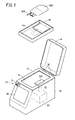
- FIG. 1 is a perspective view of a blood collection device according to an embodiment of the present invention
- FIG. FIG. 2 is an exploded perspective view showing the internal structure of the blood collection device of FIG. 1
- FIG. 2 is a block diagram showing the configuration of the blood sampling device of FIG. 1
- 2 is a flow chart showing the operation of the blood collection device of FIG. 1
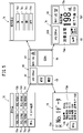
- FIG. 2 is an explanatory diagram showing the transition of display images on the display input unit of the blood sampling apparatus of FIG. 1
- FIG. 5 is a flow chart showing the operation of the blood sampling apparatus in the blood sampling abnormality monitoring process of FIG. 4
- FIG. 10 is a graph showing changes in blood collection volume according to determination pattern 1.
- FIG. FIG. FIG. 1 is a perspective view of a blood collection device according to an embodiment of the present invention
- FIG. FIG. 2 is an exploded perspective view showing the internal structure of the blood collection device of FIG. 1
- FIG. 2 is a block diagram showing the configuration of the blood sampling device of FIG. 1
- 2 is a flow
- FIG. 10 is an explanatory diagram showing a warning display based on a change in blood collection volume according to determination pattern 1; 10 is a graph showing changes in blood collection volume according to determination pattern 2.
- FIG. FIG. 11 is an explanatory diagram showing a warning display based on a change in the collected blood volume according to determination pattern 2; 10 is a graph showing changes in blood collection volume according to determination pattern 3.
- FIG. 10 is an explanatory diagram showing a warning display based on a change in the collected blood volume according to determination pattern 3; 10 is a graph showing changes in blood collection volume according to determination pattern 4.
- FIG. FIG. 11 is an explanatory diagram showing a warning display based on a change in the collected blood volume according to determination pattern 4;
- FIG. 11 is an explanatory diagram showing a blood collection end screen;
- the blood collection device 10 is a vacuum blood collection device that collects blood from a blood donor into a blood collection bag 200 using negative pressure. Placed and used.
- the blood collection device 10 includes a box-shaped housing 14 in which a storage chamber 12 for housing a blood collection bag 200 is formed, and a lid 16 provided on the top of the storage chamber 12 of the box-shaped housing 14 so as to be freely opened and closed. and
- the housing chamber 12 is formed in a concave shape having a peripheral wall portion and a bottom portion, and is open upward.
- a hinge 30 is provided on the rear side of the housing chamber 12, and the lid body 16 is attached to the hinge 30 so as to be openable and closable.
- the lid 16 covers from above a blood collection bag 200 placed on a storage tray 18, which will be described later, in a closed state.
- the lid 16 is transparent so that the blood collection bag 200 during blood collection can be visually recognized from the outside.
- a sealing member 15 for hermetically sealing the lid 16 and the storage chamber 12 is provided at the upper end of the storage chamber 12 or the lower end of the lid 16 .
- the lid 16 is provided with a tube holder 21 that holds a blood collection tube 202 connected to the blood collection bag 200 in a state of being led out to the outside.
- the storage chamber 12 is provided with a storage tray 18 for placing a blood collection bag 200, a swing mechanism 20, and a bracket 22.
- the storage dish 18 is arranged to be rockable in order to mix the anticoagulant contained in the blood collection bag 200 with the blood (whole blood) collected from the blood donor, and is rocked via the bracket 22 . It is connected to the movement mechanism 20 .
- a mounting portion 18a is provided on the bottom surface of the storage tray 18, and is fixed to the bracket 22 through the mounting portion 18a by a method such as screwing.
- a detachable connection structure using the attraction force of a magnet may be configured.
- the bracket 22 is provided with a load sensor 22a.
- the load sensor 22a detects the weight of the blood collection bag 200 accommodated in the container 18.
- the swinging mechanism 20 includes a swinging motor, and generates a swinging motion for moving the storage tray 18 in the direction of inclination along the circumferential direction.
- the storage chamber 12 of the blood sampling apparatus 10 includes an exhaust pump 24 that exhausts the air inside the storage chamber 12 to generate a negative pressure, and a pressure sensor that detects the negative pressure in the storage chamber 12. 26 and a clamp portion 28 for blocking or conducting the blood collection tube 202 are provided.
- an operation panel 32 is provided on the front of the housing 14 .
- the operation panel 32 is provided with a power switch 34 , an operation switch 36 and a display input section 38 .
- the operation switch 36 is configured as, for example, a mechanical button switch.
- the operation switch 36 may be an electrostatic or pressure-sensitive switch or the like.
- the operation switches 36 include, for example, a start/stop switch 40 and a clamp release switch 42.
- the start/stop switch 40 is a switch for manually starting and stopping blood sampling.
- the clamp release switch 42 is for manually releasing the clamped state (closed state) of the blood collection tube 202 by the clamp section 28 .
- the clamp release switch 42 does not need to be provided on the operation panel 32, and may be provided at a location other than the operation panel 32 as a lever-operated switch such as an operation lever (not shown).
- the display input unit 38 consists of, for example, a liquid crystal display and has a touch panel function. Therefore, the display input unit 38 also serves as an input unit that receives input for operating the blood collection device 10 .
- the blood sampling device 10 further includes a storage unit 48 and a control unit 44.
- the storage unit 48 stores blood collection data on blood collected from blood donors.
- the control unit 44 includes a time measurement unit 44a, a flow rate detection unit 44b, and a change rate detection unit 50.
- the time measurement unit 44a measures the blood collection start time, the elapsed time from the blood collection start, and the blood collection end time.
- the flow rate detection unit 44b detects the amount of collected blood based on the weight of the blood collection bag 200 and the specific gravity of the blood, and also detects the amount of collected blood, which is the rate of blood collection, based on the amount of change in the amount of collected blood per unit time. Changes in the amount of collected blood with respect to time are stored in the storage unit 48 as collected blood amount data.
- the collected blood volume data in the storage unit 48 is updated as needed along with the elapsed time.
- the rate-of-change detector 50 obtains the rate of change in the collected blood flow rate (flow rate of change) by differentiating the data of the collected blood flow rate.
- control unit 44 controls each unit of the blood sampling device 10 to perform the blood sampling operation.
- the control unit 44 acquires the amount of blood collected, the start time of blood collection, the end time of blood collection, the time required for blood collection, the blood collection abnormality, and the end information as blood collection data, and stores them in the storage unit 48 as blood collection data.
- the blood sampling abnormality recorded in the blood sampling data includes a warning display due to a drop in the blood sampling volume and the rate of change in the flow volume.
- a determination pattern is stored in the storage unit 48 together with the above-described blood collection data and blood collection data.
- the determination pattern is used for matching with the blood collection data, and is data for identifying the cause of the decrease in the blood collection volume. It includes parameters related to changes in the collected blood flow after the drop.
- the control unit 44 monitors the blood collection volume during the blood collection operation, and when a decrease in the blood collection volume is detected, compares the blood collection volume data with the determination pattern to determine the cause of the decrease in the blood collection volume. Then, a warning display including factors for decreasing the collected blood flow rate is displayed on the display unit.
- FIG. 1 The operations and functions of the blood collection device 10 will be described below with reference to FIGS. 4 to 14.
- FIG. 1 is a diagrammatic representation of the blood collection device 10.
- the process proceeds to step S10 in FIG. A screen 60 is displayed.
- the setting screen 60 includes a blood collection bag selection button 62, an aspiration pressure selection button 64, a history display button 66, and a blood collection start button 68.
- the blood collection bag selection button 62 displays the type and capacity (eg, 200 ml) of the blood collection bag 200 as initial settings.
- the control unit 44 switches the display of the display input unit 38 to the blood collection selection screen 72 shown in the upper left of FIG.
- the blood collection selection screen 72 includes bag selection buttons 72a to 72f displaying the type (manufacturer name) and capacity of the blood collection bag 200, and a return button 72g.
- the control unit 44 When the operator selects the desired volume and type of blood collection bag 200 on the blood collection selection screen 72 , the control unit 44 returns the display of the display input unit 38 to the setting screen 60 . Then, the control unit 44 causes the blood collection bag selection button 62 on the setting screen 60 to display the type and capacity of the blood collection bag 200 being selected. If the return button 72g is touched without selecting any of the bag selection buttons 72a to 72f on the blood collection selection screen 72, the control unit 44 does not change the type and capacity of the blood collection bag 200, and displays the display on the display input unit 38. to return to the setting screen 60 . In this case, the blood collection bag selection button 62 on the setting screen 60 displays the type and capacity of the blood collection bag 200 before selection.
- the control unit 44 When the operator touches the suction pressure selection button 64, the control unit 44 causes the display input unit 38 to display the suction pressure setting screen 74 on the upper right of FIG.
- the suction pressure setting screen 74 displays an OFF setting button 74a, a weak setting button 74b, a medium setting button 74c, and a strong setting button 74d for setting the negative pressure for blood sampling.
- the OFF setting button 74a When the OFF setting button 74a is selected, the control unit 44 is set to collect blood only by free falling due to the height difference between the blood donor and the blood collection bag 200 without performing suction during blood collection.
- the weak setting button 74b By selecting the weak setting button 74b, the medium setting button 74c, and the strong setting button 74d, it is possible to select weak, medium, or strong negative pressure during blood sampling. Negative pressure increases in order of weak, medium and strong settings.
- the control unit 44 intermittently operates the exhaust pump 24 so that the negative pressure in the preset range of -10 mmHg to -100 mmHg is obtained during blood sampling.
- the middle setting button 74c the control unit 44 intermittently operates the exhaust pump 24 so that the negative pressure is in the range of -40 mmHg to -150 mmHg during blood sampling.
- the control unit 44 intermittently operates the exhaust pump 24 so that the negative pressure is in the range of -80 mmHg to -200 mmHg during blood sampling.
- the blood collection data screen 76 includes data selection buttons 76a and 76b, a return button 76c, and a blood collection data display portion 76d.
- the collected blood data display section 76d displays the collected blood data including data number, blood collection amount, blood collection start time, blood collection end time, blood collection time, abnormality history due to flow rate decrease (for example, flow rate is zero), and the like.
- the data selection buttons 76a and 76b are selected, the blood collection data screen 76 switches to display the previous and next blood collection data.
- the return button 76c is selected, the setting screen 60 is restored.
- the operator places a predetermined blood collection bag 200 on the container 18, sets the blood collection tube 202 in the clamp portion 28, closes the lid 16, and punctures the blood donor with the blood collection needle. This completes the preparation for blood collection. Thereafter, when the operator touches the blood collection start button 68 on the setting screen 60 of FIG. 5, the blood collection device 10 starts blood collection.
- step S20 in FIG. 4 the process moves to step S20 in FIG. 4, and the blood collection device 10 starts blood collection.
- the control unit 44 starts operating the rocking mechanism 20 and the exhaust pump 24 . After the value detected by the pressure sensor 26 reaches a predetermined negative pressure, the control section 44 opens the clamp section 28 to start collecting blood from the donor.
- the blood collection screen 78 includes a blood collection bag display portion 62A, an aspiration pressure selection button 64, a history display button 66, a blood collection state display portion 78d, a blood collection remaining amount display portion 78e, and an end prediction display portion 78f.
- the blood collection bag display section 62A has only display functions that cannot be selected, and displays the type of the blood collection bag 200 being selected and the amount of blood collected.
- the suction pressure selection button 64 is a selectable button, and when this is selected, the screen shifts to the suction pressure setting screen 74 on the upper right of FIG. The operator can check the condition of the blood donor and, if necessary, operate the suction pressure setting screen 74 to change the suction pressure during blood sampling and adjust the blood sampling speed.
- the control unit 44 performs blood sampling abnormality monitoring of step S40.
- the flow rate detection unit 44b of the control unit 44 calculates the blood collection flow rate (ml/min) from the weight increase of the blood collection bag 200 per fixed blood collection time.
- the collected blood volume is stored in the storage unit 48 as collected blood volume data in association with the time.
- the collected blood volume data is updated sequentially.
- the control unit 44 monitors the collected blood flow rate detected by the flow rate detection unit 44b, and detects a decrease in the collected blood flow rate.
- a decrease in the collected blood volume is determined, for example, by whether or not the collected blood volume has fallen below a predetermined threshold value (eg, 80%) with respect to the collected blood volume in the initial stage of blood collection.
- a predetermined threshold value eg, 80%
- step S401 the control unit 44 reads the collected blood volume data from the storage unit 48, and from the collected blood volume data, the transition of the collected blood volume before the collected blood volume decreases (element A), and the flow rate change rate when the collected blood volume decreases (element B). , the minimum blood collection rate (element C), and the change in the blood collection rate after the blood collection rate has decreased (element D).
- the transition of the blood collection volume before the blood collection volume decreases can be obtained, for example, by taking a moving average of the blood collection volume for a predetermined period before detecting a decrease in the blood collection volume.
- the rate of change in the flow rate when the blood collection rate decreases can be obtained, for example, as the rate of change in the flow rate when a decrease in the blood collection rate is detected.
- the rate of change in flow rate (element B) when the collected blood flow rate is decreased may be obtained as an average of the rate of change in the flow rate in a predetermined time range before and after detection of the decrease in the collected blood rate.
- the minimum collected blood flow rate (element C) is the lowest value of the collected blood flow rate in the range until the rate of change in the blood collection rate (element B) when the blood collection rate decreases changes from negative to positive and the reduction in the collected blood flow stops. Ask. Since the collected blood volume is 0 or more, the minimum value of the collected blood volume takes a value of 0 or more.
- the transition of the collected blood flow rate after the collected blood flow rate decreased is a predetermined value after the rate of change in the collected blood rate (element B) when the collected blood rate decreased from negative to positive and the decrease in the collected blood rate stopped in the collected blood rate data.
- the element D may be obtained as an average value of the collected blood volume during the period ⁇ t2 instead of the maximum value of the collected blood volume.
- step S402 determines which of the determination patterns stored in the storage unit 48 corresponds to the combination of the elements A to D obtained in step S401.
- the storage unit 48 stores determination patterns 1 to 4.
- FIG. The control unit 44 determines which of the determination patterns 1 to 4 corresponds.
- step S402 if the collected blood flow data does not correspond to any of the determination patterns 1 to 4, the process returns to step S401.
- determination pattern 1 element A is equal to or greater than a first flow rate (eg, 30 ml/min) and element B is equal to or greater than a first rate of change (eg, 30 ml/min/sec).
- a first flow rate eg, 30 ml/min
- a first rate of change eg, 30 ml/min/sec
- Such a change in the blood collection flow rate may occur when the blood collection tube 202 (blood collection line) is blocked by Klemme, Kochel, or the like, when the blood collection tube 202 is blocked by the clamp portion 28 of the blood collection device 10, or when the blood collection tube 202 is blocked. This is the case where the blood collection tube 202 is mechanically blocked, such as when the blood collection tube 202 is blocked by bending or being crushed.
- step S403 the control unit 44 causes the display input unit 38 to display the warning display 102 (see FIG. 8).
- the warning display 102 includes a display indicating that the blood collection line is blocked as the cause of the decrease in blood collection flow rate.
- the warning display 102 also includes countermeasures against the cause of deterioration.
- the warning display 102 presents countermeasures to release the clamp portion 28 of the blood collection device 10 and countermeasures to release the blockage due to bending or crushing of the blood collection line.
- element A is less than the first flow rate (30 ml/min)
- element B is less than the first rate of change (30 ml/min/sec)
- element C is less than the second flow rate (5 ml/min).
- factor D is less than the second flow rate (5 ml/min).
- the collected blood volume data matching the determination pattern 2 shows a gradual decrease in the collected blood volume, and the collected blood volume (or its moving average value; element A) immediately before detecting a decrease in the collected blood volume is 30 ml. / minute.
- the rate of change in blood collection volume gradually decreases below 30 ml/min/sec, and the blood collection volume after the decrease (elements C and D) transitions between zero and a low flow rate (less than 5 ml/min) close to zero.
- a change in the amount of blood collected as shown in FIG. 9 occurs when a thrombus is formed in the blood collection needle or the blood collection tube 202 and the flow path is blocked. Therefore, when the collected blood flow data matches the determination pattern 2, the control unit 44 causes the warning display 104 to be displayed in step S403 of FIG.
- the warning display 104 includes a display to the effect that a thrombus has formed inside the tip of the needle or the blood collection line as a cause of the decrease in blood collection volume.
- the warning display 104 also includes countermeasures against the cause of deterioration.
- the blood sampling apparatus 10 presents a coping method prompting an operation to remove the thrombus according to the thrombus removal procedure in the warning display 104 .
- the processing in the case of matching with the determination pattern 3 in step S402 of FIG. 6 will be described.
- element A is less than the first flow rate (30 ml/min)
- element B is less than the first rate of change (30 ml/min/sec)
- element C is less than the second flow rate (5 ml/min).
- element D is equal to or greater than the third flow rate (10 ml/min).
- the collected blood volume data matching the determination pattern 3 shows a gradual decrease in the collected blood volume, and the collected blood volume (or its moving average value; element A) immediately before detecting a decrease in the collected blood volume is 30 ml. / minute.
- the rate of change in blood collection volume is less than 30 ml/min/sec, the factor B is satisfied.
- the collected blood flow drops to zero (element C), but then spontaneously recovers.
- Such a change in blood collection volume is thought to be caused by the tip of the blood collection needle coming into contact with the inner wall of the blood vessel, temporarily blocking the blood inflow path.
- the decrease in the blood collection volume is caused by the fact that the puncture position of the blood collection needle by the person in charge of blood collection is close to the bent position of the elbow, and the puncture position shifts due to the donor's body movement, and the thickness of the donor's blood vessel and the blood collection needle.
- the influence of the puncture angle is considered.
- the flow velocity of the collected blood volume decreases to near zero, but the flow volume recovers naturally thereafter.
- the blood volume in the blood vessel decreases due to blood collection, the blood collection needle sticks to the inner wall of the blood vessel again, and the blood collection volume repeatedly decreases.
- step S402 of FIG. 6 when the collected blood flow data matches the judgment pattern 3, the control unit 44 proceeds to step S403 and causes the display input unit 38 to display the warning display 106.
- FIG. 12 the warning display 106 includes a display indicating that the reason for the decrease in the collected blood flow rate is the contact of the tip of the needle with the inner wall of the blood vessel.
- the warning display 106 also includes a display of how to deal with a decrease in the collected blood flow rate. That is, the warning display 106 presents a coping method for prompting adjustment of the needle tip position.
- element B is the first change rate (eg, 30 ml / min / sec) or less
- element C is the second flow rate (eg, 5 ml / min) or more
- element D is the second flow rate (5 ml / min) ⁇
- a fourth flow rate range (eg, 35 ml/min).
- the collected blood flow rate data shown in FIG. meets Also, the minimum flow rate (element C) when the blood collection rate is reduced is greater than the second flow rate (5 ml/min). Further, the element D has a second flow rate (5 ml/min) to a fourth flow rate (35 ml/min). In other words, the flow rate is so low that a sufficient amount of blood cannot be collected within the prescribed blood collection time. Therefore, the collected blood flow data shown in FIG. 13 matches the determination pattern 4.
- the collected blood flow data shown in FIG. 13 is caused by a decrease in blood supply to the inside of the blood vessel punctured by the blood collection needle.
- the cause is that the donor fell asleep during blood collection, and the blood supply to the blood vessels in the arm decreased as the heart rate decreased, and the surface temperature of the arm from which blood was collected decreased. Blood vessels may constrict, reducing blood supply.
- the control unit 44 determines that the decrease in the blood collection rate is the decrease in the blood supply to the blood sampling site, In step S403, the control unit 44 causes the display input unit 38 to display a warning display 108 indicating that the blood supply to the warning display blood sampling site is decreasing.
- the warning display 108 includes a display indicating that the blood flow in the arm is decreasing due to sleep or a decrease in body temperature as a cause of the decrease in blood collection volume.
- the warning display 108 also includes countermeasures against the cause of deterioration. For example, as a coping method, a call to wake the donor, keeping the arm warm, and measures to encourage the donor to perform a gripping motion are presented.
- step S403 of FIG. 6 the warning displays 102 to 108 including the cause of the decrease in the collected blood flow are displayed on the display input unit 38 of the blood collection device 10, so that the person in charge of blood collection becomes aware of the decrease in the collected blood flow that requires attention. Furthermore, according to the countermeasures presented by the warning displays 102 to 108, it is possible to quickly take measures to eliminate factors that reduce the blood collection volume.
- step S404 the control unit 44 determines whether or not the collected blood volume has recovered.
- the control unit 44 can detect the recovery of the blood collection volume by monitoring whether the blood collection volume has recovered to the blood collection volume of the element A. If the blood collection volume has not recovered (NO), the blood collection device 10 continues the warning display on the display input unit 38 . When the collected blood volume recovers, the blood collection device 10 cancels the warning display on the display input unit 38 and continues monitoring the collected blood volume.
- the collected blood volume begins to recover from time t1, and at time t2, the collected blood volume returns to the value before the flow rate decreased. Therefore, at time t2, recovery of the collected blood volume in step S404 is detected, and the warning display is cancelled. When the warning display is canceled in step S404, the process returns to step S400, and the control unit 44 continues monitoring whether or not the collected blood flow rate has decreased.
- the blood sampling device 10 waits until a predetermined blood sampling time (eg, 15 minutes) has elapsed, a preset blood sampling amount (eg, 200 ml, 400 ml, etc.) has been reached, or blood sampling has occurred. Blood collection end processing is performed based on the input of the blood collection end instruction by the person in charge.
- a predetermined blood sampling time e.g, 15 minutes
- a preset blood sampling amount eg, 200 ml, 400 ml, etc.
- step S50 the control section 44 closes the clamp section 28 (see FIG. 3), stops the exhaust pump 24 and the rocking mechanism 20, and opens the storage chamber 12 to the atmosphere.
- the control unit 44 records the blood collection start time, the blood collection end time, the blood collection required time, the blood collection amount, and the fact that the blood collection is completed in the blood collection data, and ends the blood collection.
- the control unit 44 causes the display input unit 38 to display a blood collection end screen 90 shown in FIG.
- the blood collection end screen 90 includes a blood collection bag display portion 62A, an aspiration setting display portion 64A, an end display portion 92, a blood collection data display portion 94, and a confirmation button 96.
- the blood collection bag display portion 62A displays the type and blood collection amount of the selected blood collection bag 200
- the suction setting display portion 64A displays the suction setting state.
- the end display portion 92 displays a normal end indicating that the blood collection reaches the set blood collection amount and is completed.
- the blood collection data display section 94 displays the actual blood collection amount, blood collection start/end time, blood collection time, presence/absence of a warning display associated with a decrease in the blood collection amount, and the like.
- the confirmation button 96 is selected on the blood collection end screen 90, the blood collection device 10 proceeds to step S10 in FIG. 4 and displays the setting screen 60 (see FIG. 5) for receiving the next blood collection.
- the blood collection device 10 and blood collection method of this embodiment have the following effects.
- the blood collection device 10 of this embodiment is a blood collection device 10 that collects whole blood by storing a blood collection bag 200 in a storage chamber 12 and making the storage chamber 12 negative pressure.
- a sensor 22a a control unit 44 that detects the amount of blood collected that is a change in the amount of blood collected per unit time
- a storage unit 48 that stores blood collection data including changes in the amount of blood collected with respect to time, and a determination pattern, and during blood collection.
- a display input unit 38 for displaying blood collection information including the blood collection volume of the control unit 44.
- the control unit 44 monitors the blood collection volume, and when a decrease in the blood collection volume is detected, determines that the blood collection volume data in the storage unit 48. By comparing with patterns 1 to 4, the factor of decrease in blood collection volume is determined, and warning displays 102 to 108 including the factors of decrease in blood collection volume are displayed on the display input unit 38 .
- the decrease in blood collection volume that requires attention is displayed on the display input unit 38 of the blood collection device 10 along with the cause. It is possible to prevent the occurrence of toxic formulations.
- the judgment patterns 1 to 4 are the transition of the blood collection flow before the blood collection flow decreases (element A), the flow rate change rate when the blood collection flow decreases (element B), and the blood collection flow after the blood collection flow decreases. (elements C, D). According to this configuration, it is possible to identify causes such as blockage of the blood collection line, aggregation of thrombus, sticking of the blood collection needle to the blood vessel, and reduction of the blood flow rate in the blood vessel from the collected blood flow data.
- the control unit 44 determines the cause of the decrease in the collected blood flow rate by connecting the blood collection bag 200 and the blood collection needle. It may be determined that the blood collection line (blood collection tube 202) is blocked, and a warning display 102 to the effect that the blood collection line is blocked may be displayed on the display input unit . According to this configuration, it is possible to promote appropriate countermeasures against mechanical obstruction due to bending or trampling of the blood collection tube 202 .
- the control unit 44 determines the blood collection factor as the blood collection reduction factor. It may be determined that the cause is caused by blood coagulation inside the needle or the blood collection line, and a warning display 104 to the effect that blood coagulation has occurred may be displayed on the display input unit 38 . According to this configuration, it is possible to encourage appropriate measures against a decrease in the amount of collected blood due to blood coagulation.
- the control unit 44 returns the collected blood volume data to the collected blood volume before the blood collection volume decreased after the collected blood volume gradually decreased to zero or a low flow rate in the vicinity of zero.
- the cause of the decrease in the collected blood flow rate is that the blood collection needle sticks to the inner wall of the blood vessel, and a warning display 106 to the effect that the blood collection needle sticks to the inner wall of the blood vessel is displayed on the display input unit 38. You may let According to this configuration, it is possible to promote an appropriate countermeasure against a decrease in the amount of collected blood due to sticking of the blood collection needle to the inner wall of the blood vessel.
- the collected blood flow rate data stabilizes at a low flow rate to the extent that a sufficient blood collection volume cannot be secured within a prescribed blood collection time after the collected blood flow rate gradually decreases
- the decrease in the amount of blood collected from the donor is due to the decrease in the amount of blood supplied to the blood collection site of the donor. You may let According to this configuration, it is possible to prompt an appropriate countermeasure against a decrease in the blood flow rate of the blood vessel punctured by the blood collection needle.
- the control unit 44 determines that, in the blood collection volume data, the blood collection volume (element A) before the blood collection volume decreases is equal to or greater than the first flow rate (for example, 30 ml/min), and When the rate of change in flow rate (element B) at time is faster than the first rate of change (for example, 30 ml/min/sec), the factor of decrease in the blood collection rate is the blood collection line (blood collection tube) connecting the blood collection bag 200 and the blood collection needle. 202) may be determined to be due to mechanical blockage.
- the first flow rate for example, 30 ml/min
- the factor of decrease in the blood collection rate is the blood collection line (blood collection tube) connecting the blood collection bag 200 and the blood collection needle. 202) may be determined to be due to mechanical blockage.
- the control unit 44 determines that, in the collected blood flow rate data, the flow rate change rate (element B) when the collected blood flow rate decreases is below the first change rate (for example, 30 ml/min/sec) and that the collected blood flow rate
- the collected blood flow rate (elements C and D) after reduction falls below a second flow rate (e.g., 5 ml/min) near zero flow rate and exceeds a third flow rate (e.g., 10 ml/min) greater than the second flow rate within a certain period of time. If the recovery does not occur, it may be determined that the cause of the decrease in blood collection volume is the occurrence of blood coagulation inside the blood collection needle or blood collection line (blood collection tube 202).
- the control unit 44 determines that, in the collected blood flow rate data, the flow rate change rate (element B) when the collected blood flow rate decreases is below the first change rate (for example, 30 ml/min/sec) and that the collected blood flow rate
- the collected blood flow rate (elements C and D) after reduction falls below a second flow rate (e.g., 5 ml/min) near zero flow rate and exceeds a third flow rate (e.g., 10 ml/min) greater than the second flow rate within a certain period of time. It may be configured to determine that the blood collection needle sticks to the inner wall of the blood vessel as the cause of the decrease in the collected blood flow rate when the blood collection rate has recovered to the maximum.
- the control unit 44 determines that, in the collected blood flow rate data, the flow rate change rate (element B) when the collected blood flow rate decreases is below the first change rate (for example, 30 ml/min/sec) and that the collected blood flow rate
- the collected blood flow rate (elements C and D) after reduction is stable at a low speed between the second flow rate (eg, 5 ml/min) and the fourth flow rate (eg, 35 ml/min)
- the collected blood flow rate A declining factor is determined to be a declining blood supply to the donor vessel.
- a load sensor 22a for detecting the weight of the blood collection bag 200, a control unit 44 for detecting the blood collection volume that is a change in the blood collection volume per unit time, collection blood volume data including changes in the collection blood volume with respect to time, and determination patterns are stored. and a display input unit 38 for displaying blood collection information including the amount of blood collected during blood collection.
- the control unit 44 monitors the collected blood flow rate, and when the control unit 44 detects a decrease in the collected blood flow rate (YES in step S400), the collected blood flow data and the determination pattern are performed.
- Steps S401 and S402 are performed to determine the cause of the decrease in the collected blood volume by comparing the above, and Step S403 in which the control unit 44 causes the display input unit 38 to display warning displays 102 to 108 including the cause of the decrease in the collected blood volume.
- the decrease in the blood collection volume that requires attention is displayed on the display input unit 38 along with the cause. You can prevent it from happening.
Abstract
採血バッグ(200)を収容室(12)に収容し収容室(12)を陰圧とすることで全血を採取する採血装置(10)及び採血方法であって、制御部(44)は、採血流量を監視し、採血流量の低下を検出した場合には、採血流量データと判定パターンとを対比して、採血流量の低下要因を判断し、表示入力部(38)に採血流量の低下要因を含む警告表示(102~108)を表示させる。
Description
本発明は、ドナーから全血を採取する採血装置及び採血方法に関する。
例えば、特開2004-81305号公報には、陰圧を利用してドナーから採血バッグ内への採血を行う採血装置が開示されている。この採血装置は、採血バッグを採血装置のバッグ収容室に収容するとともに、採血容器に付属した採血針をドナーの腕の静脈に穿刺し、排気ポンプでバッグ収容室の内部を陰圧状態にすることで採血を行う。
このような陰圧を用いた採血においては、様々な要因により採血流量が低下することがある。採血流量の低下により、規定の採血時間を超過した場合には、採血が打ち切られ、容量不足の血液製剤が発生する要因となり、廃棄ロスを招くことがある。
従来の採血装置においても、採血流量を監視して、採血流量が低下した際に、警報を発して採血担当者の注意を促す機能を備えたものもある。採血を行う看護師等の採血担当者は、採血装置の警報表示とドナーの状態を観察しながら、採血装置の吸引圧力の調整、採血ラインの異常の有無の確認、採血している腕の保温、ドナーへの声掛けと手のグリップ等を行わせる、等の方法により血液流量の低下防止を図っている。
採血担当者は、採血済みバッグの後処理や採血帳票の作成や採血終了したドナーへの対応等に追われることにより、採血中のドナーの監視に集中できない状況も存在する。さらに、採血流量の低下は様々な要因で発生し、採血流量の低下が一時的で直ぐに採血流量が回復する場合もあるため、過度な警報が多発してしまい、本当に注意が必要な採血流量低下の兆しを採血担当者が見逃してしまうおそれがある。
本発明は、注意すべき採血流量の低下を検出して採血担当者に対応を促すことができる採血装置及び採血方法を提供することを目的とする。
以下の開示の一観点は、採血バッグを収容室に収容し前記収容室を陰圧とすることで全血を採取する採血装置であって、採血バッグの重量を検出する荷重センサと、単位時間当たりの採血量の変化である採血流量を検出する制御部と、採血流量の時間に対する変化を含む採血流量データと、判定パターンとを格納する記憶部と、採血中の採血流量を含む採血情報を表示する表示部と、を備え、前記制御部は、採血流量を監視し、採血流量の低下を検出した場合には、前記記憶部の採血流量データと判定パターンとを対比して、採血流量の低下要因を判断し、前記表示部に採血流量の低下要因を含む警告表示を表示させる、採血装置にある。
別の一観点は、採血バッグの重量を検出する荷重センサと、単位時間当たりの採血量の変化である採血流量を検出する制御部と採血流量の時間に対する変化を含む採血流量データと、判定パターンとを格納する記憶部と、採血中の採血流量を含む採血情報を表示する表示部と、を備え、採血バッグを収容した収容室を陰圧にして全血を採取する採血装置で行われる、採血方法であって、前記制御部が採血流量を監視するステップと、前記制御部が採血流量の低下を検出した場合には、採血流量データと判定パターンとを対比して採血流量の低下要因を判断するステップと、前記制御部が前記表示部に採血流量の低下要因を含む警告表示を表示させるステップと、を行う採血方法にある。
上記観点の採血装置及び採血方法によれば、注意すべき採血流量の低下を検出できるとともに採血流量の低下要因を警告表示に含ませることで、採血担当者に適切な対応を促すことができる。
以下、本発明の好適な実施形態を挙げ、添付の図面を参照して詳細に説明する。
図1に示すように、本実施形態に係る採血装置10は、陰圧を利用して供血者から血液を採血バッグ200内に採血する真空採血装置であり、献血ルームや献血用のバス等に配置されて用いられる。
採血装置10は、採血バッグ200を収容するための収容室12が形成された箱型の筐体14と、箱型の筐体14の収容室12の上部に開閉自在に設けられた蓋体16とを備える。収容室12は、周壁部と底部とを備えた凹状に形成されており、上方に開口している。図2に示すように、収容室12の背面側には、ヒンジ30が設けられており、ヒンジ30には蓋体16が開閉可能に取り付けられている。
図1に示すように、蓋体16は、閉状態で後述する収容皿18に載置された採血バッグ200を上方から覆う。蓋体16は、採血中の採血バッグ200を外部から視認することができるように透明に構成されている。収容室12の上端部又は蓋体16の下端部には、蓋体16と収容室12とを気密にシールするシール部材15が設けられている。また、蓋体16には、採血バッグ200に接続された採血チューブ202を外部に導出させた状態で保持するチューブホルダ21が設けられている。
図2に示すように、収容室12内には、採血バッグ200を載置するための収容皿18と、揺動機構20と、ブラケット22とが設けられている。収容皿18は、採血バッグ200内に収容された抗血液凝固剤と供血者から採血した血液(全血)とを混和させるために、揺動可能に配置されており、ブラケット22を介して揺動機構20に接続されている。収容皿18の底面には、取付部18aが設けられており、取付部18aを通じてブラケット22にねじ止め等の方法で固定される。なお、取付部18a及びブラケット22による固定に代えて、磁石の吸着力を利用した脱着可能な接続構造として構成してもよい。
ブラケット22には、荷重センサ22aが設けられている。荷重センサ22aは、収容皿18に収容された採血バッグ200の重量を検出する。揺動機構20は、揺動用モータを備えており、収容皿18の傾斜方向を円周方向に沿って移動させる揺動運動を発生させる。
図3に示すように、採血装置10の収容室12には、収容室12の内部のエアを排気して陰圧を発生させる排気ポンプ24と、収容室12内の陰圧を検出する圧力センサ26と、採血チューブ202を閉塞又は導通させるクランプ部28が設けられている。
図1に示すように、筐体14の正面には、操作パネル32が設けられている。操作パネル32には、電源スイッチ34、操作スイッチ36及び表示入力部38が設けられている。操作スイッチ36は、例えば、機械式のボタンスイッチとして構成される。操作スイッチ36は、静電式又は感圧式のスイッチ等であってもよい。操作スイッチ36は、例えば、開始/停止スイッチ40、クランプ解除スイッチ42を含む。開始/停止スイッチ40は、採血の開始及び停止を手動で行うためのスイッチである。また、クランプ解除スイッチ42は、クランプ部28による採血チューブ202のクランプ状態(閉塞状態)を手動で解除するためのものである。なお、クランプ解除スイッチ42は、操作パネル32に設ける必要はなく、不図示の操作レバー等のレバー動作するスイッチとして、操作パネル32とは別の箇所に設けられてもよい。
表示入力部38は、例えば液晶ディスプレイよりなり、タッチパネル機能を備えている。そのため、表示入力部38は、採血装置10を操作するための入力を受け付ける入力部を兼ねる。
図3に示すように、採血装置10は、さらに記憶部48と制御部44とを備える。記憶部48は、供血者から採取された血液についての採血データを格納する。
制御部44は、時刻計測部44aと、流量検出部44bと、変化率検出部50とを備える。このうち、時刻計測部44aは、採血開始時刻、採血開始からの経過時間、採血終了時刻を計測する。流量検出部44bは、採血バッグ200の重量と血液の比重に基づいて採血量を検出するとともに、単位時間当たりの採血量の変化量にもとづいて、採血速度である採血流量を検出する。採血流量の時間に対する変化は、採血流量データとして記憶部48に格納される。記憶部48の採血流量データは経過時間に伴って随時更新される。変化率検出部50は、採血流量データの微分をとることにより、採血流量の変化率(流量変化率)を求める。
また、制御部44は、採血装置10の各部を制御して採血動作を行う。制御部44は、採血毎に、採血データとして、採血量、採血開始時刻、採血終了時刻、採血所要時間、採血異常、及び終了情報を採血毎に取得し、採血データとして記憶部48に格納する。採血データに記録される採血異常には、採血流量及び流量変化率の低下による警告表示等が含まれている。
記憶部48には、上記の採血データ、採血流量データとともに、判定パターンが格納されている。判定パターンは、採血流量データとマッチングに使用され、採血流量の低下原因を特定するためのデータであり、採血流量が低下する直前の採血流量の推移、採血流量低下時の流量変化率、採血流量低下後の採血流量の推移に関するパラメータを含む。
制御部44は、採血動作の間、採血流量の監視を行い、採血流量の低下が検出された場合には、採血流量データと判定パターンとを対比して、採血流量の低下要因を判断する。そして、採血流量の低下要因を含む警告表示を表示部に表示させる。
以下、採血装置10の動作及び機能について図4~図14を参照して説明する。
採血装置10の正面の電源スイッチ34(図1参照)を押して採血装置10の電源を投入すると、図4のステップS10に移行し、採血装置10は、表示入力部38に、図5に示す設定画面60を表示させる。図5の中央に示すように設定画面60は、採血バッグ選択ボタン62と、吸引圧選択ボタン64と、履歴表示ボタン66と、採血開始ボタン68とを含む。
採血バッグ選択ボタン62には、初期設定値としての採血バッグ200の種類及び容量(例えば、200ml)が表示される。採血バッグ選択ボタン62をタッチすると、制御部44は、表示入力部38の表示を、図5の左上に示す採血選択画面72に切り換える。採血選択画面72には、採血バッグ200の種類(メーカー名)及び容量が表示されたバッグ選択ボタン72a~72f及び復帰ボタン72gが含まれる。
採血選択画面72において、オペレータが所望の容量及び種類の採血バッグ200を選択すると、制御部44は、表示入力部38の表示を設定画面60に復帰させる。そして、制御部44は、設定画面60の採血バッグ選択ボタン62に選択中の採血バッグ200の種類及び容量を表示させる。なお、採血選択画面72において、バッグ選択ボタン72a~72fを選択せずに復帰ボタン72gをタッチすると、制御部44は、採血バッグ200の種類及び容量を変更せずに、表示入力部38の表示を設定画面60に戻す。この場合には、設定画面60の採血バッグ選択ボタン62には、選択前の採血バッグ200の種類及び容量が表示される。
オペレータが吸引圧選択ボタン64をタッチすると、制御部44は、表示入力部38に図5の右上の吸引圧設定画面74を表示させる。吸引圧設定画面74には、採血を行う際の陰圧を設定するOFF設定ボタン74a、弱設定ボタン74b、中設定ボタン74c及び強設定ボタン74dの各ボタンが表示されている。OFF設定ボタン74aを選択すると、制御部44が採血の際に、吸引を行わずに、供血者と採血バッグ200との高低差による自然落下のみで採血を行う設定となる。
弱設定ボタン74b、中設定ボタン74c及び強設定ボタン74dの選択により、採血時の陰圧の弱、中、強を選択できる。陰圧は、弱設定、中設定及び強設定の順に増大する。例えば、弱設定ボタン74bを選択すると、制御部44が採血の際に、予め設定された-10mmHg~-100mmHgの範囲の陰圧となるように、排気ポンプ24を間欠動作させる制御を行う。また、例えば、中設定ボタン74cを選択すると、制御部44が採血の際に、-40mmHg~-150mmHgの範囲の陰圧となるように、排気ポンプ24を間欠動作させる制御を行う。また、例えば、強設定ボタン74dを選択すると、制御部44が採血の際に、例えば-80mmHg~-200mmHgの範囲の陰圧となるように、排気ポンプ24を間欠動作させる制御を行う。なお、上記の数値範囲に重複が有るがこれは標準的な動作において設定可能な数値範囲を示すものであり、具体的な設定陰圧は、弱設定、中設定及び強設定の順に増大する関係を満たすように、上記の数値範囲から適宜設定される。
吸引圧設定画面74において、オペレータによって何れかの陰圧設定が行われると、図5の中央の設定画面60に復帰する。オペレータが履歴表示ボタン66をタッチすると、制御部44は、過去の採血における採血データを記憶部48から読み出し、図5の左下の採血データ画面76を表示入力部38の画面に表示させる。採血データ画面76は、データ選択ボタン76a、76b、復帰ボタン76c及び採血データ表示部76dを含む。採血データ表示部76dには、データ番号とともに、採血量、採血開始時刻、採血終了時刻、採血時間及び流量低下(例えば、流量ゼロ)による異常履歴等を含む採血データが表示される。データ選択ボタン76a、76bを選択すると、採血データ画面76は、前後の採血データの表示に切り換わる。復帰ボタン76cを選択すると、設定画面60に復帰する。
オペレータが、図1に示すように、所定の採血バッグ200を収容皿18の上に載置し、採血チューブ202をクランプ部28にセットして蓋体16を閉じ、採血針を供血者に穿刺することで、採血の準備が完了する。その後、オペレータが図5の設定画面60の採血開始ボタン68をタッチすると、採血装置10が採血を開始する。
採血開始ボタン68を選択すると、図4のステップS20に移行し、採血装置10が採血を開始する。制御部44は、揺動機構20及び排気ポンプ24を作動開始させる。制御部44は、圧力センサ26の検出値が所定の陰圧に到達した後、クランプ部28を開放して供血者からの血液の採血を開始する。
その後、ステップS30に移行し、制御部44は、表示入力部38に、図5の右下の採血画面78を表示させる。採血画面78は、採血バッグ表示部62Aと、吸引圧選択ボタン64と、履歴表示ボタン66と、採血状態表示部78dと、採血残量表示部78eと、終了予測表示部78fとを含む。採血バッグ表示部62Aは、選択することができない表示機能のみとなっており、選択中の採血バッグ200の種類と採血量が表示される。吸引圧選択ボタン64は、選択可能なボタンとなっており、これを選択すると図5の右上の吸引圧設定画面74に移行する。オペレータは供血者の状態を確認し、必要に応じて、吸引圧設定画面74を操作することで、採血の途中で吸引圧を変更して採血速度を調節できる。
ステップS30の処理と並行して、制御部44は、ステップS40の採血異常監視を行う。ステップS40の採血異常の監視において、制御部44の流量検出部44bは、一定の採血時間当たりの採血バッグ200の重量増加から採血流量(ml/分)を算出する。採血流量は時刻と対応付けられて採血流量データとして記憶部48に格納される。採血流量データは逐次更新される。以下、図6を参照しつつ、採血流量の監視処理の詳細について説明する。
制御部44は、流量検出部44bが検出した採血流量を監視し、採血流量の低下を検出する。採血流量の低下は、例えば、採血初期の採血流量に対して採血流量が所定の閾値(例えば80%)を下回ったか否かで判断する。ステップS400で、制御部44が採血流量の低下を検出した場合には、ステップS401に移行して判定パターンと採血流量データとのマッチングを行って、採血量の低下要因を判断する処理を開始する。
ステップS401において、制御部44は、記憶部48から採血流量データを読み込み、採血流量データから、採血流量低下前の採血流量の推移(要素A)、採血流量低下時の流量変化率(要素B)、最低採血流量(要素C)、採血流量低下後の採血流量の推移(要素D)を抽出する。
採血流量低下前の採血流量の推移(要素A)は、例えば、採血流量の低下を検出する前の所定期間の採血流量の移動平均をとることで求めることができる。
採血流量低下時の流量変化率(要素B)は、例えば、採血流量の低下を検出した際の流量変化率として求めることができる。なお、採血流量低下時の流量変化率(要素B)は、採血流量の低下を検出した前後の所定の時間範囲の流量変化率の平均として求めてもよい。
最低採血流量(要素C)は、採血流量データにおいて、採血流量低下時の流量変化率(要素B)がマイナスからプラスに変化して採血流量の低下が止まるまでの範囲における採血流量の最低値を求める。採血流量は0以上であるため、採血流量の最低値は0以上の値を取る。
採血流量低下後の採血流量の推移(要素D)は、採血流量データにおいて、採血流量低下時の流量変化率(要素B)がマイナスからプラスに変化して採血流量の低下が止まった後の所定の期間Δt2(例えば、1分)の採血流量の最大値として求めることができる。なお、要素Dは、採血流量の最大値に代えて期間Δt2の採血流量の平均値として求めてもよい。
次に、制御部44は、ステップS402に移行して、ステップS401で求めた要素A~Dの組み合わせが、記憶部48に格納された判定パターンの何れに該当するかを判断する。本実施形態においては、記憶部48には判定パターン1~4が格納されている。制御部44は、この判定パターン1~4の何れかに該当するかを求める。なお、ステップS402において、採血流量データが判定パターン1~4の何れにも該当しない場合には、ステップS401に戻る。
以下、判定パターン1~4の何れかに該当する採血流量データを参照しつつ、処理の具体例について説明する。
ステップS402で判定パターン1にマッチングする場合の処理について説明する。判定パターン1は、要素Aが第1流量(例えば、30ml/分)以上であり、且つ要素Bが第1変化率(例えば、30ml/分/秒)以上である。図7に示すように、判定パターン1にマッチングする採血流量データは、採血流量が30ml/分の正常(定常的)な採血流量から、突然採血流量がゼロ付近に変化する場合である。このような採血流量の変化は、採血チューブ202(採血ライン)が、クレンメやコッヘル等で閉塞される場合、採血チューブ202が採血装置10のクランプ部28で閉塞される場合、又は、採血チューブ202が折れ曲がりや踏みつぶし等で閉塞された場合のように、採血チューブ202が機械的に閉塞された場合である。
採血流量データが判定パターン1にマッチングする場合には、図6のステップS403に移行する。ステップS403において、制御部44は、警告表示102(図8参照)を表示入力部38に表示させる。図8に示すように、警告表示102は、採血流量の低下原因として、採血ラインが閉塞している旨を示す表示を含む。警告表示102には、低下原因に対する対処方法も含まれる。ここでは、警告表示102は、採血装置10のクランプ部28を解放する対応策と、採血ラインの折れ曲がりや踏みつぶし等による閉塞を解除する対応策を提示する。
次に、図6のステップS402で判定パターン2にマッチングする場合の処理について説明する。判定パターン2は、要素Aが第1流量(30ml/分)未満であり、要素Bが第1変化率(30ml/分/秒)未満であり、要素Cが第2流量(5ml/分)未満であり、要素Dが第2流量(5ml/分)未満である。図9に示すように、判定パターン2にマッチングする採血流量データは、採血流量が徐々に低下しており、採血流量低下を検出する直前の採血流量(又はその移動平均値;要素A)が30ml/分を下回っている。また、採血流量の変化率が30ml/分/秒未満で徐々に低下し、低下後の採血流量(要素C、D)がゼロとゼロ付近の低流速(5ml/分未満)で推移する。
図9に示すような採血流量の変化は、採血針又は採血チューブ202に血栓が形成されてゆき、流路が閉塞状態となって生じる。そこで、採血流量データが判定パターン2にマッチングする場合には、制御部44は、図6のステップS403において、警告表示104を表示させる。
図10に示すように、警告表示104は、採血流量の低下原因として、針先又は採血ラインの内部で血栓が形成されている旨の表示を含む。また、警告表示104には、低下原因に対する対処方法も含まれる。ここでは、採血装置10は、警告表示104において、血栓除去手順に従って、血栓を除去する操作を促す対処方法を提示する。
次に、図6のステップS402で判定パターン3にマッチングする場合の処理について説明する。判定パターン3は、要素Aが第1流量(30ml/分)未満であり、要素Bが第1変化率(30ml/分/秒)未満であり、要素Cが第2流量(5ml/分)未満であり、要素Dが第3流量(10ml/分)以上である。図11に示すように、判定パターン3にマッチングする採血流量データは、採血流量が徐々に低下しており、採血流量低下を検出する直前の採血流量(又はその移動平均値;要素A)が30ml/分を下回っている。また、採血流量の変化率が30ml/分/秒未満で徐々に低下し要素Bを満たす。採血流量はゼロまで低下(要素C)するが、その後自然に流量が回復する。
このような採血流量の変化は、採血針の先端が血管内壁に接触することで、血液流入経路が一時的に閉塞状態となることが考えられる。この場合の採血流量低下の原因は、採血担当者による採血針の穿刺位置が肘の折り曲げ位置に近く、ドナーの体動により穿刺位置がずれてしまうことや、ドナーの血管の太さと採血針の穿刺角度の影響が考えられる。このような採血針の血管壁への貼り付きで採血流量が低下すると、血管内の血液の供給量が増加して血管が膨張し、自然に貼り付き状態が解消する。そのため、図11に示すように、採血流量の流速がゼロ付近にまで低下するが、その後自然に流量が回復する。ただし、採血により血管内の血液量が低下すると、再び採血針が血管内壁に貼り付いて、採血流量の低下を繰り返す挙動を示す。
そこで、図6のステップS402において、採血流量データが判定パターン3にマッチングした場合には、制御部44はステップS403に移行して、警告表示106を表示入力部38に表示させる。図12に示すように、警告表示106は採血流量の低下原因が針先の血管内壁への接触であるとする表示を含む。また、警告表示106には、採血流量の低下に対する対処方法の表示も含まれる。すなわち、警告表示106には、針先位置の調整を促す対処方法を提示する。
次に、図6のステップS402で判定パターン4にマッチングする場合の処理について説明する。判定パターン4は、要素Bが第1変化率(例えば、30ml/分/秒)以下、要素Cが第2流量(例えば、5ml/分)以上、要素Dが第2流量(5ml/分)~第4流量(例えば、35ml/分)の範囲である。図13に示す採血流量データは、採血流量の低下が検出された時点において、採血流量の変化率が比較的小さく、採血流量の低下が徐々に進んでおり、要素B(30ml/分/秒)を満たしている。そして、採血流量の低下の際の最低流量(要素C)が第2流量(5ml/分)よりも大きい。また、要素Dは、第2流量(5ml/分)~第4流量(35ml/分)となっている。すなわち、規定の採血時間内に十分な採血量を確保できない程度の低流速となっている。従って、図13に示す採血流量データは、判定パターン4にマッチする。
図13に示す採血流量データは、採血針を穿刺している血管内部への血液供給量の低下により生じる。原因としては、ドナーが採血中に寝入ってしまい、心拍数が低下することに伴って腕の血管への血液の供給が低下すること、及び、採血している腕の表面温度が低下することで血管が収縮してしまい、血液供給が減少することが考えられる。
そこで、本実施形態の採血装置10では、採血流量データが判定パターン4にマッチする場合には、制御部44が採血流量の低下要因を採血部位への血液供給の低下であるものと判断し、ステップS403において、制御部44は、警告表示採血部位への血液供給が減少している旨の警告表示108を表示入力部38に表示させる。警告表示108は、図14に示すように、採血流量の低下原因として、睡眠又は体温低下により腕の血流が減少している旨を示す表示を含む。警告表示108には、低下原因に対する対処方法も含まれる。例えば、対処方法として、ドナーを覚醒させるための声掛け、腕の保温、及びドナーのグリップ動作を促す対応策を提示する。
図6のステップS403において、採血装置10の表示入力部38に採血流量の低下原因を含む警告表示102~108が表示されることにより、採血担当者は注意が必要な採血流量の低下に気づくことができ、さらに警告表示102~108で提示された対処方法に従って迅速に採血流量の低下要因を取り除く措置を取ることができる。
その後、ステップS404において、制御部44は、採血流量が回復したか否かを判断する。ここでは、制御部44は採血流量が要素Aの採血流量に回復したかを監視することで、採血流量の回復を検出することができる。採血流量が回復していない場合(NO)には、採血装置10は、表示入力部38の警告表示を継続する。採血流量が回復した場合には、採血装置10は表示入力部38の警告表示を解除して、採血流量の監視を継続する。
例えば、図7の採血流量データにおいては、時刻t1から採血流量が回復し始め、時刻t2において採血流量が流量低下前の値に復帰する。そのため、時刻t2において、ステップS404の採血流量の回復が検出され、警告表示が解除されることとなる。ステップS404で警告表示が解除されると、再びステップS400に戻り、制御部44は採血流量低下の有無の監視を継続する。
上記のステップS400~ステップS404の処理は、採血が完了するまで継続して行われる。
その後、図4のステップS50に示すように、採血装置10は、所定の採血時間(例えば、15分)の経過、予め設定された採血量(例えば、200mlや400ml等)への到達、又は採血担当者による採血終了指示の入力に基づいて、採血終了処理を行う。
ステップS50において、制御部44はクランプ部28(図3参照)を閉塞させるとともに、排気ポンプ24及び揺動機構20を停止させ、収容室12を大気開放する。また、制御部44は、採血データに、採血開始時刻、採血終了時刻、採血所要時間、採血量とともに、採血が完了した旨の記録を行い、採血を終了する。
また、制御部44は、表示入力部38に、図15に示す採血終了画面90を表示させる。採血終了画面90は、採血バッグ表示部62Aと、吸引設定表示部64Aと、終了表示部92と、採血データ表示部94と、確認ボタン96と、が含まれる。採血バッグ表示部62Aは、選択した採血バッグ200の種類及び採血量が表示され、吸引設定表示部64Aには吸引設定状態が表示される。終了表示部92には、採血が設定された採血量に到達して完了したことを示す正常終了の表示がなされる。また、採血データ表示部94には、実際の採血量、採血開始・終了時刻、採血時間、採血流量低下に伴う警告表示の有無等が表示される。採血終了画面90において、確認ボタン96を選択すると、採血装置10は、図4のステップS10に移行して次の採血を受け付ける設定画面60(図5参照)を表示する。
本実施形態の採血装置10及び採血方法は、以下の効果を奏する。
本実施形態の採血装置10は、採血バッグ200を収容室12に収容し収容室12を陰圧とすることで全血を採取する採血装置10であって、採血バッグ200の重量を検出する荷重センサ22aと、単位時間当たりの採血量の変化である採血流量を検出する制御部44と、採血流量の時間に対する変化を含む採血流量データと、判定パターンとを格納する記憶部48と、採血中の採血流量を含む採血情報を表示する表示入力部38と、を備え、制御部44は、採血流量を監視し、採血流量の低下を検出した場合には、記憶部48の採血流量データと判定パターン1~4とを対比して、採血流量の低下要因を判断し、表示入力部38に採血流量の低下要因を含む警告表示102~108を表示させる。
上記の構成によれば、採血装置10の表示入力部38に、注意が必要な採血流量の低下が原因とともに表示されるため、採血担当者の採血流量の低下の見逃しを防ぎ、採血量が不足した製剤の発生を防止できる。
上記の採血装置10において、判定パターン1~4は、採血流量が低下する前の採血流量の推移(要素A)、採血流量低下時の流量変化率(要素B)、採血流量低下後の採血流量の推移(要素C、D)に関するデータを含んでもよい。この構成によれば、採血流量データから、採血ラインの閉塞、血栓の凝集、採血針の血管貼り付き、及び血管内流量の低下等の原因を特定することができる。
上記の採血装置10において、制御部44は、採血流量データが、定常的な採血流量から急激にゼロ付近に低下した場合には、採血流量の低下要因を、採血バッグ200と採血針とを結ぶ採血ライン(採血チューブ202)が閉塞したことによるものと判断し、表示入力部38に、採血ラインが閉塞した旨の警告表示102を表示させてもよい。この構成によれば、採血チューブ202の折れ曲がりや踏み潰し等による機械的な閉塞に対して適切な対応を促すことができる。
上記の採血装置10において、制御部44は、採血流量データが、採血流量が徐々に低下して流量ゼロ又は流量ゼロ付近の低流量を継続する場合には、採血流量の低下要因を、前記採血針又は前記採血ラインの内部で血液の凝集が発生したことによるものと判断し、表示入力部38に、血液の凝集が発生した旨の警告表示104を表示させてもよい。この構成によれば、血液の凝集に基づく採血流量の低下に対して、適切な対応を促すことができる。
上記の採血装置10において、制御部44は、採血流量データが、採血流量が徐々に低下して流量ゼロ又は流量ゼロ付近の低流量に低下した後、採血流量の低下前の採血流量に復帰した場合には、採血流量の低下要因を、前記採血針が血管内壁に貼り付いたことによるものと判断し、表示入力部38に、採血針が血管内壁に貼り付いた旨の警告表示106を表示させてもよい。この構成によれば、採血針の血管内壁への貼り付きに基づく採血流量の低下に対して、適切な対応を促すことができる。
上記の採血装置10において、制御部44は、採血流量データが、採血流量が徐々に低下した後、規定の採血時間内に十分な採血量を確保できない程度の低流速で安定した場合には、採血流量の低下要因をドナーの採血部位への血液供給量の低下によるものと判断し、表示入力部38に、ドナーの採血部位への血液供給量が低下している旨の警告表示108を表示させてもよい。この構成によれば、採血針が穿刺された血管の血液流量の低下に対して、適切な対応を促すことができる。
上記の採血装置10において、制御部44は、採血流量データにおいて、採血流量が低下する前の採血流量(要素A)が第1流量(例えば、30ml/分)以上であり、且つ、採血流量低下時の流量変化率(要素B)が第1変化率(例えば、30ml/分/秒)よりも早い場合に、採血流量の低下要因を、採血バッグ200と採血針とを結ぶ採血ライン(採血チューブ202)の機械的な閉塞によるものと判断するように構成してもよい。
上記の採血装置10において、制御部44は、採血流量データにおいて、採血流量低下時の流量変化率(要素B)が第1変化率(例えば、30ml/分/秒)を下回り、且つ、採血流量低下後の採血流量(要素C、D)が流量ゼロ付近の第2流量(例えば、5ml/分)を下回って一定時間以内に第2流量より大きな第3流量(例えば、10ml/分)を上回るまで回復しない場合には、採血流量の低下要因を、採血針又は採血ライン(採血チューブ202)の内部で血液の凝集が発生したことによるものと判断するように構成してもよい。
上記の採血装置10において、制御部44は、採血流量データにおいて、採血流量低下時の流量変化率(要素B)が第1変化率(例えば、30ml/分/秒)を下回り、且つ、採血流量低下後の採血流量(要素C、D)が流量ゼロ付近の第2流量(例えば、5ml/分)を下回って一定時間以内に第2流量より大きな第3流量(例えば、10ml/分)を上回るまで回復した場合には、採血流量の低下要因を、採血針が血管内壁に貼り付いたものと判断するように構成してもよい。
上記の採血装置10において、制御部44は、採血流量データにおいて、採血流量低下時の流量変化率(要素B)が第1変化率(例えば、30ml/分/秒)を下回り、且つ、採血流量低下後の採血流量(要素C、D)が第2流量(例えば、5ml/分)と第4流量(例えば、35ml/分)との間の低速で安定している場合には、採血流量の低下要因を、ドナーの血管への血液供給量が低下しているものと判断する。
採血バッグ200の重量を検出する荷重センサ22aと、単位時間当たりの採血量の変化である採血流量を検出する制御部44と採血流量の時間に対する変化を含む採血流量データと、判定パターンとを格納する記憶部48と、採血中の採血流量を含む採血情報を表示する表示入力部38と、を備え、採血バッグ200を収容した収容室12を陰圧にして全血を採取する採血装置10で行われる、採血方法であって、制御部44が採血流量を監視するステップS400と、制御部44が採血流量の低下を検出した場合(ステップS400のYES)には、採血流量データと判定パターンとを対比して採血流量の低下要因を判断するステップS401、S402と、制御部44が表示入力部38に採血流量の低下要因を含む警告表示102~108を表示させるステップS403と、を行う。
上記の採血方法によれば、表示入力部38に、注意が必要な採血流量の低下が原因とともに表示されるため、採血担当者の採血流量の低下の見逃しを防ぎ、採血量が不足した製剤の発生を防止できる。
上記において、本発明について好適な実施形態を挙げて説明したが、本発明は上記実施形態に限定されるものではなく、本発明の趣旨を逸脱しない範囲において、種々の改変が可能なことは言うまでもない。
Claims (11)
- 採血バッグを収容室に収容し前記収容室を陰圧とすることで全血を採取する採血装置であって、
採血バッグの重量を検出する荷重センサと、
単位時間当たりの採血量の変化である採血流量を検出する制御部と、
採血流量の時間に対する変化を含む採血流量データと、判定パターンとを格納する記憶部と、
採血中の採血流量を含む採血情報を表示する表示部と、を備え、
前記制御部は、
採血流量を監視し、
採血流量の低下を検出した場合には、前記記憶部の採血流量データと判定パターンとを対比して、採血流量の低下要因を判断し、
前記表示部に採血流量の低下要因を含む警告表示を表示させる、
採血装置。 - 請求項1記載の採血装置であって、
前記判定パターンは、採血流量が低下する前の採血流量の推移、採血流量低下時の流量変化率、採血流量低下後の採血流量の推移に関するデータを含む、
採血装置。 - 請求項1又は2記載の採血装置であって、
前記制御部は、
採血流量データが、定常的な採血流量から急激にゼロ付近に低下した場合には、採血流量の低下要因を、採血バッグと採血針とを結ぶ採血ラインが閉塞したことによるものと判断し、
前記表示部に、前記採血ラインが閉塞した旨の警告表示を表示させる、
採血装置。 - 請求項1又は2記載の採血装置であって、前記制御部は、
採血流量データが、採血流量が徐々に低下して流量ゼロ又は流量ゼロ付近の低流量を継続する場合には、採血流量の低下要因を、採血針又は採血ラインの内部で血液の凝集が発生したことによるものと判断し、
前記表示部に、血液の凝集が発生した旨の警告表示を表示させる、
採血装置。 - 請求項1又は2記載の採血装置であって、前記制御部は、
採血流量データが、採血流量が徐々に低下して流量ゼロ又は流量ゼロ付近の低流量に低下した後、採血流量の低下前の採血流量に復帰した場合には、採血流量の低下要因を、採血針が血管内壁に貼り付いたことによるものと判断し、
前記表示部に、採血針が血管内壁に貼り付いた旨の警告表示を表示させる、
採血装置。 - 請求項1又は2記載の採血装置であって、前記制御部は、
採血流量データが、採血流量が徐々に低下した後、規定の採血時間内に十分な採血量を確保できない程度の低流速で安定した場合には、採血流量の低下要因をドナーの採血部位への血液供給量の低下によるものと判断し、
前記表示部に、ドナーの採血部位への血液供給量が低下している旨の警告表示を表示させる、
採血装置。 - 請求項2記載の採血装置であって、前記制御部は、
採血流量データにおいて、定常時の採血流量が第1流量以上であり、且つ、採血流量低下時の流量変化率が第1変化率よりも早い場合に、採血流量の低下要因を、採血バッグと採血針とを結ぶ採血ラインの機械的な閉塞によるものと判断する、
採血装置。 - 請求項2記載の採血装置であって、前記制御部は、
採血流量データにおいて、採血流量低下時の流量変化率が第1変化率を下回り、且つ、採血流量低下後の採血流量が流量ゼロ付近の第2流量を下回って一定時間以内に前記第2流量より大きな第3流量を上回るまで回復しない場合には、採血流量の低下要因を、採血針又は採血ラインの内部で血液の凝集が発生したことによるものと判断する、
採血装置。 - 請求項2記載の採血装置であって、前記制御部は、
採血流量データにおいて、採血流量低下時の流量変化率が第1変化率を下回り、且つ、採血流量低下後の採血流量が流量ゼロ付近の第2流量を下回って一定時間以内に前記第2流量より大きな第3流量を上回るまで回復した場合には、採血流量の低下要因を、採血針が血管内壁に貼り付いたものと判断する、
採血装置。 - 請求項2記載の採血装置であって、前記制御部は、
採血流量データにおいて、採血流量低下時の流量変化率が第1変化率を下回り、且つ、採血流量低下後の採血流量が第2流量と第4流量との間の低速で安定している場合には、採血流量の低下要因を、ドナーの血管への血液供給量が低下しているものと判断する、
採血装置。 - 採血バッグの重量を検出する荷重センサと、単位時間当たりの採血量の変化である採血流量を検出する制御部と採血流量の時間に対する変化を含む採血流量データと、判定パターンとを格納する記憶部と、採血中の採血流量を含む採血情報を表示する表示部と、を備え、採血バッグを収容した収容室を陰圧にして全血を採取する採血装置で行われる、採血方法であって、
前記制御部が採血流量を監視するステップと、
前記制御部が採血流量の低下を検出した場合には、採血流量データと判定パターンとを対比して採血流量の低下要因を判断するステップと、
前記制御部が前記表示部に採血流量の低下要因を含む警告表示を表示させるステップと、
を行う採血方法。
Priority Applications (1)
| Application Number | Priority Date | Filing Date | Title |
|---|---|---|---|
| JP2023500697A JPWO2022176600A1 (ja) | 2021-02-18 | 2022-02-01 |
Applications Claiming Priority (2)
| Application Number | Priority Date | Filing Date | Title |
|---|---|---|---|
| JP2021-024556 | 2021-02-18 | ||
| JP2021024556 | 2021-02-18 |
Publications (1)
| Publication Number | Publication Date |
|---|---|
| WO2022176600A1 true WO2022176600A1 (ja) | 2022-08-25 |
Family
ID=82932034
Family Applications (1)
| Application Number | Title | Priority Date | Filing Date |
|---|---|---|---|
| PCT/JP2022/003795 WO2022176600A1 (ja) | 2021-02-18 | 2022-02-01 | 採血装置及び採血方法 |
Country Status (2)
| Country | Link |
|---|---|
| JP (1) | JPWO2022176600A1 (ja) |
| WO (1) | WO2022176600A1 (ja) |
Citations (6)
| Publication number | Priority date | Publication date | Assignee | Title |
|---|---|---|---|---|
| JPH02213353A (ja) * | 1989-02-13 | 1990-08-24 | Nissho Corp | 採血装置 |
| JPH0554993B2 (ja) * | 1988-05-17 | 1993-08-13 | Terumo Corp | |
| JPH0653158B2 (ja) * | 1990-07-24 | 1994-07-20 | 川澄化学工業株式会社 | 定量採血装置 |
| JPH07148248A (ja) * | 1994-07-11 | 1995-06-13 | Terumo Corp | 採血装置 |
| JP2005534346A (ja) * | 2001-10-13 | 2005-11-17 | バクスター・インターナショナル・インコーポレイテッド | インラインロイコフィルタを介した、血液成分および添加剤溶液の流れを変更する、血液処理システムおよび方法 |
| JP2017038805A (ja) * | 2015-08-20 | 2017-02-23 | テルモ株式会社 | 体外循環管理装置、体外循環装置及び体外循環管理装置の制御方法 |
-
2022
- 2022-02-01 JP JP2023500697A patent/JPWO2022176600A1/ja active Pending
- 2022-02-01 WO PCT/JP2022/003795 patent/WO2022176600A1/ja active Application Filing
Patent Citations (6)
| Publication number | Priority date | Publication date | Assignee | Title |
|---|---|---|---|---|
| JPH0554993B2 (ja) * | 1988-05-17 | 1993-08-13 | Terumo Corp | |
| JPH02213353A (ja) * | 1989-02-13 | 1990-08-24 | Nissho Corp | 採血装置 |
| JPH0653158B2 (ja) * | 1990-07-24 | 1994-07-20 | 川澄化学工業株式会社 | 定量採血装置 |
| JPH07148248A (ja) * | 1994-07-11 | 1995-06-13 | Terumo Corp | 採血装置 |
| JP2005534346A (ja) * | 2001-10-13 | 2005-11-17 | バクスター・インターナショナル・インコーポレイテッド | インラインロイコフィルタを介した、血液成分および添加剤溶液の流れを変更する、血液処理システムおよび方法 |
| JP2017038805A (ja) * | 2015-08-20 | 2017-02-23 | テルモ株式会社 | 体外循環管理装置、体外循環装置及び体外循環管理装置の制御方法 |
Also Published As
| Publication number | Publication date |
|---|---|
| JPWO2022176600A1 (ja) | 2022-08-25 |
Similar Documents
| Publication | Publication Date | Title |
|---|---|---|
| EP3187201B1 (en) | Portable medical device | |
| JP4558481B2 (ja) | 創傷処置装置 | |
| EP1790284B1 (en) | Sphygmomanometer | |
| EP2647395A1 (en) | Power saving control system for negative pressure wound therapy pumps | |
| EP1110566A2 (en) | Extracorporeal blood processing method and apparatus | |
| JP5442796B2 (ja) | 血液成分採取装置 | |
| EP3378511B1 (en) | Medical pump and control method therefor | |
| TW201023822A (en) | Blood pressure measuring device | |
| WO2022176600A1 (ja) | 採血装置及び採血方法 | |
| CN102667785A (zh) | 适配阈值窗口的方法、控制设备、医学治疗装置以及医学监视装置 | |
| JP2002336350A (ja) | 自動輸液装置 | |
| JP3603036B2 (ja) | 自動血圧測定装置 | |
| JPS6323644A (ja) | 定量採血装置 | |
| EP3924013A1 (en) | Fluid and air volume measurement system for a breast pump assembly | |
| US20220355018A1 (en) | Devices and methods for managing chest or wound drainage | |
| JP6981341B2 (ja) | 流量監視装置、輸液装置及び異常報知方法 | |
| US20120165685A1 (en) | Plasmapheresis donor display and method of use | |
| JP7454585B2 (ja) | 採血装置及びその停電復帰方法 | |
| JP2785114B2 (ja) | 輸液装置 | |
| WO2021150999A1 (en) | Devices and methods for managing chest or wound drainage | |
| JP2022126466A (ja) | 採血装置及び採血装置の誤動作防止方法 | |
| JP2022126468A (ja) | 移動採血車の集中監視システム及び移動採血車 | |
| JPH0542210A (ja) | 輸液装置 | |
| JP2021045373A (ja) | 採血装置及びその採血方法 | |
| JP2021045389A (ja) | 採血装置及び採血システム |
Legal Events
| Date | Code | Title | Description |
|---|---|---|---|
| 121 | Ep: the epo has been informed by wipo that ep was designated in this application |
Ref document number: 22755921 Country of ref document: EP Kind code of ref document: A1 |
|
| ENP | Entry into the national phase |
Ref document number: 2023500697 Country of ref document: JP Kind code of ref document: A |
|
| NENP | Non-entry into the national phase |
Ref country code: DE |
|
| 122 | Ep: pct application non-entry in european phase |
Ref document number: 22755921 Country of ref document: EP Kind code of ref document: A1 |