WO2022176400A1 - 内視鏡 - Google Patents
内視鏡 Download PDFInfo
- Publication number
- WO2022176400A1 WO2022176400A1 PCT/JP2021/048343 JP2021048343W WO2022176400A1 WO 2022176400 A1 WO2022176400 A1 WO 2022176400A1 JP 2021048343 W JP2021048343 W JP 2021048343W WO 2022176400 A1 WO2022176400 A1 WO 2022176400A1
- Authority
- WO
- WIPO (PCT)
- Prior art keywords
- wire pulling
- rotation
- pulling member
- wire
- rotation restricting
- Prior art date
- Legal status (The legal status is an assumption and is not a legal conclusion. Google has not performed a legal analysis and makes no representation as to the accuracy of the status listed.)
- Ceased
Links
Images




Classifications
-
- G—PHYSICS
- G02—OPTICS
- G02B—OPTICAL ELEMENTS, SYSTEMS OR APPARATUS
- G02B23/00—Telescopes, e.g. binoculars; Periscopes; Instruments for viewing the inside of hollow bodies; Viewfinders; Optical aiming or sighting devices
- G02B23/24—Instruments or systems for viewing the inside of hollow bodies, e.g. fibrescopes
- G02B23/2476—Non-optical details, e.g. housings, mountings, supports
-
- A—HUMAN NECESSITIES
- A61—MEDICAL OR VETERINARY SCIENCE; HYGIENE
- A61B—DIAGNOSIS; SURGERY; IDENTIFICATION
- A61B1/00—Instruments for performing medical examinations of the interior of cavities or tubes of the body by visual or photographical inspection, e.g. endoscopes; Illuminating arrangements therefor
-
- A—HUMAN NECESSITIES
- A61—MEDICAL OR VETERINARY SCIENCE; HYGIENE
- A61B—DIAGNOSIS; SURGERY; IDENTIFICATION
- A61B1/00—Instruments for performing medical examinations of the interior of cavities or tubes of the body by visual or photographical inspection, e.g. endoscopes; Illuminating arrangements therefor
- A61B1/005—Flexible endoscopes
- A61B1/008—Articulations
-
- G—PHYSICS
- G02—OPTICS
- G02B—OPTICAL ELEMENTS, SYSTEMS OR APPARATUS
- G02B23/00—Telescopes, e.g. binoculars; Periscopes; Instruments for viewing the inside of hollow bodies; Viewfinders; Optical aiming or sighting devices
- G02B23/24—Instruments or systems for viewing the inside of hollow bodies, e.g. fibrescopes
Definitions
- the present invention relates to endoscopes.
- An endoscope includes an insertion section to be inserted into the body of an observation target, and an operation section connected to a proximal end portion of the insertion section.
- the operation part includes a wire pulling member that pulls a wire arranged in the insertion part as it rotates to change the direction of the distal end of the insertion part, and a wire pulling member that is connected to transmit an operating force to the wire pulling member.
- the direction of the distal end of the insertion portion can be changed by rotating the angle knob.
- some endoscopes have angle knobs that are detachably attached to the operating portion.
- the angle knob is detached from the operating portion before shipment, and the angle knob is attached to the operating portion when used.
- Patent Literature 2 describes an attachment that covers an angle knob. By covering the angle knob with the attachment in this way, it is possible to reduce the operating force required to bend the bending portion.
- the present invention has been made in view of the above background, and it is an object of the present invention to provide an endoscope in which the wire pulling member does not rotate before use.
- the endoscope of the present invention includes an insertion section that is inserted into the body of an observation target, and a wire arranged in the insertion section as it rotates to pull a wire arranged in the insertion section to change the orientation of the distal end of the insertion section. and an angle knob connected to the wire pulling member to transmit the operating force to the wire pulling member, and the angle knob is removed from the wire pulling member before use.
- the angle knob is engaged with the wire pulling member in a state detached from the wire pulling member to regulate the rotation of the wire pulling member, and the wire pulling member is held at a predetermined rotational position.
- a rotation regulating member that holds the
- the rotation restricting member may be removed when used, and an angle knob may be attached instead.
- the rotation restricting member has a rotation restricting position that engages with the wire pulling member to restrict rotation of the wire pulling member, and a rotation allowing position that disengages from the engagement and allows rotation of the wire pulling member.
- the angle knob may be provided movably between the two and moved from the rotation restricting position to the rotation allowing position by being pressed by the angle knob in the process of attaching the angle knob to the wire pulling member.
- the wire pulling member may be one that is pushed by the rotation restricting member and guided to a predetermined rotational position in the process of mounting the rotation restricting member.
- the wires include a first wire that directs the distal end of the insertion section in a first direction when pulled, and a second wire that directs the distal end of the insertion section in a second direction opposite to the first direction when pulled; A third wire that is pulled to orient the tip of the insertion section in a third direction perpendicular to the first direction, and a third wire that is towed to orient the tip of the insertion section in a fourth direction opposite to the third direction.
- 4 wires wherein the wire pulling member is connected to the first and second wires and selectively pulls one of the first and second wires corresponding to the rotational direction; 3. a second wire pulling member connected to the fourth wire and selectively pulling one of the third and fourth wires corresponding to the rotational direction; the angle knob is connected to the first wire pulling member; and a second angle knob connected to the second wire pulling member.
- the rotation restricting member has a first rotation restricting portion that restricts rotation of the first wire pulling member, and a second rotation restricting portion that restricts rotation of the second wire pulling member. , the restriction on rotation of one of the second wire pulling members may be released so that the restriction on rotation of the other is released.
- the rotation restricting member includes a first rotation restricting member that restricts rotation of the first wire pulling member and a second rotation restricting member that restricts rotation of the second wire pulling member.
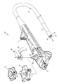
- FIG. 1 is an external view of an endoscope; FIG. It is an external view of a wire pulling mechanism.
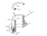
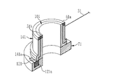
- FIG. 4 is an exploded view of the wire pulling mechanism; It is an external view of a wire pulling mechanism.
- FIG. 4 is an exploded view of the wire pulling mechanism;
- FIG. 10 is an explanatory diagram of a mechanism for releasing rotation restriction of the wire pulling member in the process of attaching the angle knob;
- FIG. 10 is an explanatory diagram of a mechanism for releasing rotation restriction of the wire pulling member in the process of attaching the angle knob;
- FIG. 10 is an explanatory diagram of a mechanism for releasing rotation restriction of the wire pulling member in the process of attaching the angle knob;
- FIG. 10 is an explanatory diagram of a mechanism for releasing rotation restriction of the wire pulling member in the process of attaching the angle knob;
- an endoscope 10 includes an insertion section 12 that is inserted into the body of an observation target. At the distal end 12a of the insertion portion 12, an illumination window 14 for emitting illumination light, an observation window 16 for receiving reflected light from an observation target, and an outlet for a treatment tool such as forceps inserted into the insertion portion 12 from a forceps opening 18. A forceps outlet 20 and the like are provided.
- a curved portion 30 is provided in the vicinity of the distal end 12a of the insertion portion 12 .
- the bending portion 30 is provided so as to be freely bendable in the vertical and horizontal directions.
- Four first to fourth wires 31 to 34 (see FIGS. 2 and 3) arranged inside the insertion portion 12 are connected to the bending portion 30 . Then, the bending portion 30 bends in the first direction (upward in this embodiment) by pulling the first wire 31 toward the proximal end side of the insertion portion 12 . Further, by pulling the second wire 32 toward the proximal end side of the insertion section 12, the second wire 32 is bent in the second direction (downward in this embodiment).
- An operation section 40 is connected to the proximal end of the insertion section 12 .
- a rotation restricting member 50 is attached to the operation portion 40 until the endoscope 10 is used.
- , 52 are mounted.
- a wire pulling mechanism 60 is provided in the operating portion 40 , and the first and second amble knobs 51 and 52 are attached to the wire pulling mechanism 60 .
- the wire pulling mechanism 60 has a first wire pulling member 61 (see FIGS. 2 and 3) to which the first and second wires 31 and 32 are connected. and connected to the first wire pulling member 61 . Then, by rotating the first angle knob 51 in one direction (counterclockwise in this embodiment), the first wire 31 is pulled to direct the distal end 12a of the insertion portion 12 upward and in the opposite direction (counterclockwise in this embodiment). By rotating it clockwise, the second wire 32 can be pulled to direct the distal end 12a of the insertion portion 12 downward.
- the wire pulling mechanism 60 also includes a second wire pulling member 62 (see FIGS. 2 and 3) to which the third and fourth wires 33 and 34 are connected. It is attached to the member 62 and connected to the second wire pulling member 62 . Then, by rotating the second angle knob 52 in one direction (counterclockwise in this embodiment), the third wire 33 is pulled to turn the distal end 12a of the insertion portion 12 leftward, and in the opposite direction (counterclockwise in this embodiment). By rotating it clockwise, the fourth wire 34 can be pulled to turn the distal end 12a of the insertion portion 12 rightward.
- a second wire pulling member 62 see FIGS. 2 and 3 to which the third and fourth wires 33 and 34 are connected. It is attached to the member 62 and connected to the second wire pulling member 62 . Then, by rotating the second angle knob 52 in one direction (counterclockwise in this embodiment), the third wire 33 is pulled to turn the distal end 12a of the insertion portion 12 leftward, and in the opposite direction (counterclockwise in this embodiment). By
- the wire pulling mechanism 60 has the above-described first and second wire pulling members 61 and 62 housed in a cylindrical body 70 and supported rotatably around an axis CL. .
- the cylindrical body 70 supports a middle plate 71 on which the first wire pulling member 61 is placed and a bottom plate 72 on which the second wire pulling member 62 is placed from the outer peripheral side.
- the first wire pulling member 61 is formed in a cylindrical shape
- the second wire pulling member 62 is formed in a shaft shape.
- the second wire pulling member 62 penetrates through the intermediate plate 71 and the first wire pulling member 61 , and its upper portion protrudes upward from the tubular body 70 .
- a first wire 31 and a second wire 32 are attached to the lower outer circumference of the first wire pulling member 61 at positions facing each other with the axis CL therebetween, and the first wire pulling member 61 moves in a direction opposite to the axis CL.
- the clockwise rotation pulls the first wire 31 and the clockwise rotation pulls the second wire 32 .
- a first engagement groove 61a and a first guide groove 61b are formed in the upper portion of the first wire pulling member 61.
- the rotation restricting member 50 includes a holder 80 that fits into the outer shell 40a (see FIG. 1) of the operation portion 40.
- the holder 80 is attached to the outer shell 40a.
- the rotation restricting member 50 (first rotation restricting portion 81) is held at a predetermined position and posture.
- the rotation of the first wire pulling member 61 is restricted by the first rotation restricting portion 81 engaged with the first engagement groove 61a, and the first wire pulling member 61 is held at a predetermined rotation position.
- the first guide groove 61b is a groove that is formed continuously with the upper end side of the first engagement groove 61a and is formed to become wider toward the upper side.
- the 1-wire pulling member 61 is guided to the aforementioned predetermined rotational position (the position where the first engagement groove 61a engages the first rotation restricting portion 81 with the rotation restricting member 50 attached to the operating portion 40). It has a function to (rotate).
- the The first rotation restricting portion 81 presses the side wall of the first guide groove 61b to rotate the first wire pulling member 61 to the above-described predetermined rotation position. This is convenient because the user does not need to adjust the rotational position of the first wire pulling member 61 when mounting the rotation restricting member 50 .
- a third wire 33 and a fourth wire 34 are attached to the lower outer periphery of the second wire pulling member 62 at positions facing each other with the axis CL therebetween, and the second wire pulling member 62 moves along the axis CL.
- a counterclockwise rotation about the center pulls the third wire 33
- a clockwise rotation pulls the fourth wire 34 .
- a second engagement groove 62a and a second guide groove 62b are formed in the upper portion of the second wire pulling member 62.
- the rotation restricting member 50 when the rotation restricting member 50 is attached to the operation portion 40, the projection-like second rotation restricting portion 82 provided on the rotation restricting member 50 is engaged with the second engagement groove 62a.
- the rotation restricting member 50 includes the holder 80 fitted to the outer shell 40a of the operating portion 40, and when the rotation restricting member 50 is attached to the operating portion 40, the holder 80 is attached to the outer shell 40a. , and the rotation restricting member 50 (second rotation restricting portion 82) is held at a predetermined position and posture.
- the rotation of the second wire pulling member 62 is restricted by the second rotation restricting portion 82 engaged with the second engagement groove 62a, and the second wire pulling member 62 is held at a predetermined rotation position.
- the second guide groove 62b is a groove that is formed continuously with the upper end side of the second engagement groove 62a and is formed so as to increase in width toward the upper side.
- the two-wire pulling member 62 is guided to the aforementioned predetermined rotational position (the position where the second engagement groove 62a engages the second rotation restricting portion 82 with the rotation restricting member 50 attached to the operating portion 40). It has a function to (rotate). That is, even if the second wire pulling member 62 is at a rotational position different from the above-described predetermined rotational position when the rotation restricting member 50 is attached, the rotation restricting member 50 is attached in the process of attaching the second wire pulling member 62 .
- the second rotation restricting portion 82 presses the side wall of the second guide groove 62b to rotate the second wire pulling member 62 to the above-described predetermined rotation position. This is convenient because the user does not need to adjust the rotational position of the second wire pulling member 62 when mounting the rotation restricting member 50 .
- the grooves (first and second guide grooves 61b, 62b) having widths narrower toward the bottom (the direction in which the rotation restricting member is attached to the endoscope) are used to prevent the rotation restricting member from moving.
- the wire pulling member is rotated (guided) to a predetermined rotational position during the installation process.
- the width of the groove is constant, and the width of the protrusion that engages with the groove is formed to decrease downward (in the direction in which the rotation restricting member is attached to the endoscope).
- the wire pulling member may be rotated (guided) to a predetermined rotational position.
- the present invention only needs to include a rotation restricting member that restricts rotation of the wire pulling member in a state in which the angle knob is removed.
- a rotation restricting member that restricts rotation of the wire pulling member in a state in which the angle knob is removed.
- the projection provided on the rotation restricting member is engaged with the groove provided on the wire pulling member to restrict the rotation of the wire pulling member.
- the rotation of the wire pulling member may be restricted by engaging a groove provided in the wire pulling member with a projection provided on the wire pulling member.
- a first rotation restricting member for restricting and releasing rotation of the first wire pulling member 61 and a second rotation restricting member for restricting and releasing rotation of the second wire pulling member 62 A regulating member may be provided to individually regulate and release the rotation of the first and second wire pulling members 61 and 62 .
- the rotation restricting member 50 is detachable from the outer shell 40a of the operation unit 40.
- the rotation restricting members first and second rotation restricting members
- the members 121 and 122 are built in the operating portion 40 (the wire pulling mechanism 100 (see FIGS. 4 and 5)).
- a second embodiment having such a configuration will be described below with reference to FIGS. 4 to 9.
- FIG. In the following description, members similar to those of the first embodiment are denoted by similar reference numerals, and description thereof is omitted.
- the wire pulling mechanism 100 of the second embodiment includes a cylindrical first wire pulling member placed on the middle plate 71 and rotatable about the axis CL. 101 is provided.
- a first engaging groove 61a is provided in the upper portion of the first wire pulling member 101, and when the first angle knob 51 is mounted on the first wire pulling member 101, the first engaging groove 61a and the first protrusion 51b are engaged. are engaged, and the first angle knob 51 and the first wire pulling member 101 are connected. As a result, the first angle knob 51 and the first wire pulling member 101 rotate together.
- a first rotation restricting groove 111 is formed in the lower portion of the first wire pulling member 101 .
- a first rotation restricting protrusion 121 a provided on a first rotation restricting member 121 is engaged with the first rotation restricting groove 111 .
- the first rotation restricting member 121 is vertically slidably supported by a vertically long first slide hole 131 formed in the intermediate plate 71 .
- the first rotation restricting member 121 protrudes from the first slide hole 131 and engages the first rotation restricting protrusion 121 a with the first rotation restricting groove 111 .
- a rotation restricting position (see FIG. 6) that restricts rotation, and a rotation that is housed inside the first slide hole 131 and releases the restriction on rotation of the first wire pulling member 101 (allows rotation). Allowable position (see FIG. 7).
- a tubular first releasing member 141 is provided on the outer periphery of the first wire pulling member 101 so as to be slidable in the direction of the axis CL (vertical direction).
- the lower end of the first release member 141 is provided with a first release protrusion 141 a that is inserted into the first rotation restriction groove 111 .
- the first rotation restricting member 121 is set at the rotation restricting position, and the first rotation restricting groove 111 is fitted with the first rotation restricting projection. 121a are engaged. This restricts the rotation of the first wire pulling member 101 .
- the first releasing projection 141a is arranged above the first rotation restricting projection 121a.
- the first rotation restricting member 121 is moved by the first engaging ring 51a during the attaching process. Pushed down to move downwards. By this movement, the first release projection 141a presses the first rotation restricting projection 121a to move the first rotation restricting member 121 to the rotation permitting position. As a result, the restriction on rotation of the first wire pulling member 101 is released.
- the first angle knob 51 in the process of attaching the first angle knob 51, not only is the first angle knob 51 connected to the first wire pulling member 101, but also the first wire pulling member 101 rotates. will be lifted at the same time.
- the wire pulling mechanism 100 of the second embodiment includes a shaft-shaped second wire pulling member 102 placed on the bottom plate 72 and rotatable about the axis CL. It has The second wire pulling member 102 and a later-described second releasing member 142 pass through the intermediate plate 71 , the first wire pulling member 101 and the first releasing member 141 , and their upper portions protrude above the tubular body 70 .
- a second engaging groove 62a is provided on the upper portion of the second wire pulling member 102, and when the second angle knob 52 is attached to the second wire pulling portion 102, the second engaging groove 62a and the second protrusion 52b are engaged. are engaged, and the second angle knob 52 and the second wire pulling member 102 are connected. As a result, the second angle knob 52 and the second wire pulling member 102 rotate together.
- a second rotation restricting groove 112 is formed in the lower portion of the second wire pulling member 102 .
- a second rotation restricting protrusion 122 a provided on a second rotation restricting member 122 is engaged with the second rotation restricting groove 112 .
- the second rotation restricting member 122 is vertically slidably supported by a vertically long second slide hole 132 formed in the bottom plate 72 .
- the second rotation restricting member 122 protrudes from the second slide hole 132 and engages the second rotation restricting projection 122 a with the second rotation restricting groove 122 , so that the second wire pulling member 102 can be moved. Between a rotation restriction position that restricts rotation and a rotation permission position that is housed inside the second slide hole 132 and releases restriction on rotation of the second wire pulling member 102 (allows rotation). to move.
- a tubular second releasing member 141 is provided on the outer periphery of the second wire pulling member 102 so as to be slidable in the direction of the axis CL (vertical direction).
- a second release protrusion 142 a that is inserted into the second rotation restriction groove 112 is provided at the lower end of the second release member 142 .
- the second rotation restricting member 122 is set at the rotation restricting position, and the second rotation restricting groove 112 has a second rotation restricting projection. 122a are engaged. Thereby, the rotation of the second wire pulling member 102 is restricted. On the other hand, in this state, the second release projection 142a is arranged above the second rotation restricting projection 122a.
- the second rotation restricting member 122 is moved by the second engagement ring 52a during the attachment process. Pushed down to move downwards. By this movement, the second release projection 142a presses the second rotation restricting projection 122a to move the second rotation restricting member 122 to the rotation permitting position. As a result, the regulation of rotation of the second wire pulling member 102 is released.
- the second angle knob 52 in the process of attaching the second angle knob 52 , not only is the second angle knob 52 connected to the second wire pulling member 102 , but also the first wire pulling member 102 rotates. will be lifted at the same time.
Landscapes
- Physics & Mathematics (AREA)
- Health & Medical Sciences (AREA)
- Life Sciences & Earth Sciences (AREA)
- Optics & Photonics (AREA)
- Surgery (AREA)
- General Physics & Mathematics (AREA)
- Astronomy & Astrophysics (AREA)
- Engineering & Computer Science (AREA)
- Molecular Biology (AREA)
- Pathology (AREA)
- Nuclear Medicine, Radiotherapy & Molecular Imaging (AREA)
- Biomedical Technology (AREA)
- Heart & Thoracic Surgery (AREA)
- Medical Informatics (AREA)
- Radiology & Medical Imaging (AREA)
- Animal Behavior & Ethology (AREA)
- General Health & Medical Sciences (AREA)
- Public Health (AREA)
- Veterinary Medicine (AREA)
- Biophysics (AREA)
- Rehabilitation Therapy (AREA)
- Instruments For Viewing The Inside Of Hollow Bodies (AREA)
- Endoscopes (AREA)
Priority Applications (2)
| Application Number | Priority Date | Filing Date | Title |
|---|---|---|---|
| JP2023500594A JP7775273B2 (ja) | 2021-02-17 | 2021-12-24 | 内視鏡 |
| US18/450,351 US20230393382A1 (en) | 2021-02-17 | 2023-08-15 | Endoscope |
Applications Claiming Priority (2)
| Application Number | Priority Date | Filing Date | Title |
|---|---|---|---|
| JP2021023408 | 2021-02-17 | ||
| JP2021-023408 | 2021-02-17 |
Related Child Applications (1)
| Application Number | Title | Priority Date | Filing Date |
|---|---|---|---|
| US18/450,351 Continuation US20230393382A1 (en) | 2021-02-17 | 2023-08-15 | Endoscope |
Publications (1)
| Publication Number | Publication Date |
|---|---|
| WO2022176400A1 true WO2022176400A1 (ja) | 2022-08-25 |
Family
ID=82930678
Family Applications (1)
| Application Number | Title | Priority Date | Filing Date |
|---|---|---|---|
| PCT/JP2021/048343 Ceased WO2022176400A1 (ja) | 2021-02-17 | 2021-12-24 | 内視鏡 |
Country Status (3)
| Country | Link |
|---|---|
| US (1) | US20230393382A1 (https=) |
| JP (1) | JP7775273B2 (https=) |
| WO (1) | WO2022176400A1 (https=) |
Cited By (1)
| Publication number | Priority date | Publication date | Assignee | Title |
|---|---|---|---|---|
| CN115813316A (zh) * | 2022-11-18 | 2023-03-21 | 广州奥立医疗设备有限公司 | 一种内窥镜 |
Citations (4)
| Publication number | Priority date | Publication date | Assignee | Title |
|---|---|---|---|---|
| JPH06125866A (ja) * | 1992-10-14 | 1994-05-10 | Terumo Corp | カテーテルの操作具 |
| JPH07178041A (ja) * | 1993-12-22 | 1995-07-18 | Fuji Photo Optical Co Ltd | 内視鏡の湾曲操作装置 |
| JPH0984754A (ja) * | 1995-09-26 | 1997-03-31 | Olympus Optical Co Ltd | 内視鏡の湾曲装置 |
| JP3181928U (ja) * | 2012-12-14 | 2013-02-28 | 富士フイルム株式会社 | 湾曲操作ノブアタッチメントの取付構造 |
-
2021
- 2021-12-24 WO PCT/JP2021/048343 patent/WO2022176400A1/ja not_active Ceased
- 2021-12-24 JP JP2023500594A patent/JP7775273B2/ja active Active
-
2023
- 2023-08-15 US US18/450,351 patent/US20230393382A1/en active Pending
Patent Citations (4)
| Publication number | Priority date | Publication date | Assignee | Title |
|---|---|---|---|---|
| JPH06125866A (ja) * | 1992-10-14 | 1994-05-10 | Terumo Corp | カテーテルの操作具 |
| JPH07178041A (ja) * | 1993-12-22 | 1995-07-18 | Fuji Photo Optical Co Ltd | 内視鏡の湾曲操作装置 |
| JPH0984754A (ja) * | 1995-09-26 | 1997-03-31 | Olympus Optical Co Ltd | 内視鏡の湾曲装置 |
| JP3181928U (ja) * | 2012-12-14 | 2013-02-28 | 富士フイルム株式会社 | 湾曲操作ノブアタッチメントの取付構造 |
Cited By (1)
| Publication number | Priority date | Publication date | Assignee | Title |
|---|---|---|---|---|
| CN115813316A (zh) * | 2022-11-18 | 2023-03-21 | 广州奥立医疗设备有限公司 | 一种内窥镜 |
Also Published As
| Publication number | Publication date |
|---|---|
| US20230393382A1 (en) | 2023-12-07 |
| JPWO2022176400A1 (https=) | 2022-08-25 |
| JP7775273B2 (ja) | 2025-11-25 |
Similar Documents
| Publication | Publication Date | Title |
|---|---|---|
| US11311180B2 (en) | Endoscope configured to change a length of a bendable part | |
| EP2997877B1 (en) | Bending control mechanism for endoscope | |
| JP5617056B2 (ja) | 挿入本体、挿入装置、回転ユニット、回転力伝達ユニット | |
| JP6113081B2 (ja) | 内視鏡 | |
| US20200305686A1 (en) | Endoscope | |
| JP2007068550A (ja) | 医療装置 | |
| JP2006000406A (ja) | 内視鏡及び内視鏡用湾曲操作補助部材 | |
| WO2019111543A1 (ja) | 内視鏡 | |
| US11060600B2 (en) | External mechanism for endoscope and endoscope apparatus | |
| JP4454956B2 (ja) | 内視鏡 | |
| JP7049366B2 (ja) | 挿入機器の操作部、操作部を有する内視鏡、操作部を有する処置具 | |
| WO2022176400A1 (ja) | 内視鏡 | |
| JP2018000741A (ja) | 内視鏡用ワイヤ牽引機構及び内視鏡 | |
| US20080132755A1 (en) | Medical device | |
| US12213648B2 (en) | Medical devices and related methods | |
| WO2016042833A1 (ja) | 内視鏡 | |
| EP1859724A1 (en) | Electric flexible endoscope device and endoscope holding device | |
| US11607113B2 (en) | External mechanism for endoscope and endoscope system | |
| JP2016067620A (ja) | 内視鏡の湾曲操作部材 | |
| CN119257526B (zh) | 锁止程度可调节的卷线模组及内窥镜 | |
| KR102658715B1 (ko) | 수술보조 장치 및 이를 포함하는 의료 기구 위치 제어 시스템 | |
| US20240324861A1 (en) | Endoscope having a steering wire actuator | |
| JP5877288B1 (ja) | 内視鏡 | |
| JP2009045084A (ja) | 内視鏡操作装置 | |
| CN114617519A (zh) | 一种内窥镜手持部 |
Legal Events
| Date | Code | Title | Description |
|---|---|---|---|
| 121 | Ep: the epo has been informed by wipo that ep was designated in this application |
Ref document number: 21926823 Country of ref document: EP Kind code of ref document: A1 |
|
| ENP | Entry into the national phase |
Ref document number: 2023500594 Country of ref document: JP Kind code of ref document: A |
|
| NENP | Non-entry into the national phase |
Ref country code: DE |
|
| 122 | Ep: pct application non-entry in european phase |
Ref document number: 21926823 Country of ref document: EP Kind code of ref document: A1 |