WO2022176325A1 - スイッチ装置 - Google Patents
スイッチ装置 Download PDFInfo
- Publication number
- WO2022176325A1 WO2022176325A1 PCT/JP2021/044828 JP2021044828W WO2022176325A1 WO 2022176325 A1 WO2022176325 A1 WO 2022176325A1 JP 2021044828 W JP2021044828 W JP 2021044828W WO 2022176325 A1 WO2022176325 A1 WO 2022176325A1
- Authority
- WO
- WIPO (PCT)
- Prior art keywords
- substrate
- switch device
- housing
- rubber sheet
- region
- Prior art date
- Legal status (The legal status is an assumption and is not a legal conclusion. Google has not performed a legal analysis and makes no representation as to the accuracy of the status listed.)
- Ceased
Links
Images



Classifications
-
- H—ELECTRICITY
- H01—ELECTRIC ELEMENTS
- H01H—ELECTRIC SWITCHES; RELAYS; SELECTORS; EMERGENCY PROTECTIVE DEVICES
- H01H9/00—Details of switching devices, not covered by groups H01H1/00 - H01H7/00
- H01H9/02—Bases, casings, or covers
-
- H—ELECTRICITY
- H01—ELECTRIC ELEMENTS
- H01H—ELECTRIC SWITCHES; RELAYS; SELECTORS; EMERGENCY PROTECTIVE DEVICES
- H01H9/00—Details of switching devices, not covered by groups H01H1/00 - H01H7/00
- H01H9/02—Bases, casings, or covers
- H01H9/04—Dustproof, splashproof, drip-proof, waterproof, or flameproof casings
-
- H—ELECTRICITY
- H01—ELECTRIC ELEMENTS
- H01H—ELECTRIC SWITCHES; RELAYS; SELECTORS; EMERGENCY PROTECTIVE DEVICES
- H01H23/00—Tumbler or rocker switches, i.e. switches characterised by being operated by rocking an operating member in the form of a rocker button
- H01H23/28—Tumbler or rocker switches, i.e. switches characterised by being operated by rocking an operating member in the form of a rocker button with three operating positions
- H01H23/30—Tumbler or rocker switches, i.e. switches characterised by being operated by rocking an operating member in the form of a rocker button with three operating positions with stable centre positions and one or both end positions unstable
Definitions
- the present invention relates to a switch device.
- the conventional switch device is configured to support the entire base of the rubber sheet using only the substrate, it has been difficult to slim down the configuration of the periphery of the fixed contact on the substrate. Therefore, it was difficult to miniaturize the substrate. Since the material cost of the substrate occupies a relatively large proportion of the material cost of the switch device, there is a demand for a technique for miniaturizing the substrate from the viewpoint of cost reduction.
- a switch device includes a knob for receiving an operation force, a substrate having a fixed contact, and a movable contact. a rubber sheet covering the substrate, and a housing for housing the substrate and the rubber sheet.
- the housing has an upper housing and a lower housing, the upper end surface of the side wall of the lower housing is formed at the same height position as the upper surface of the substrate, and the base overlaps the substrate in plan view. It has one region and a second region outside the first region, and at least a portion of the second region is supported by the upper end surface.
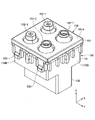
- FIG. 1 is an external perspective view of a switch device according to an embodiment
- FIG. 1 is an exploded perspective view of a switch device according to one embodiment
- FIG. FIG. 2 is a perspective cross-sectional view showing a cross section along the YZ plane of the switch device according to one embodiment; Partially enlarged view of the switch device shown in FIG. FIG. 2 is an external perspective view of a lower housing included in a switch device according to one embodiment
- FIG. 2 is an external perspective view of a lower housing (in which a substrate is placed) included in the switch device according to one embodiment
- FIG. 2 is an external perspective view of a lower housing (in which a substrate and a rubber sheet are placed) included in a switch device according to one embodiment
- FIG. 2 is an external perspective view of a rubber sheet included in a switch device according to one embodiment, as viewed from the underside of the rubber sheet;
- FIG. 1 is an external perspective view of a switch device 100 according to one embodiment.
- the X-axis direction is the front-back direction
- the Y-axis direction is the left-right direction
- the Z-axis direction is the up-down direction.
- the positive direction of the X-axis is defined as the forward direction
- the positive direction of the Y-axis is defined as the right direction
- the positive direction of the Z-axis is defined as the upward direction.
- the switch device 100 shown in FIG. 1 can be used, for example, as a switch device for operating an in-vehicle device (for example, a power window) installed in a vehicle such as an automobile.
- the switch device 100 includes a tiltable knob 120 .
- the switch device 100 is switched off when the knob 120 is in the neutral state, as shown in FIG. Further, the switch device 100 is switched to the first switch-on state or the second switch-on state by tilting the knob 120 forward (positive direction of the X-axis) or backward (negative direction of the X-axis) by the operator. state can be switched.
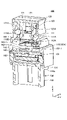
- FIG. 2 is an exploded perspective view of the switch device 100 according to one embodiment.
- FIG. 3 is a perspective cross-sectional view showing a cross section along the YZ plane of the switch device 100 according to one embodiment.
- the switch device 100 includes a knob 120, an upper housing 110, two sliders 140-1, 140-2, two cams 142-1, 142-2, a rubber sheet 150, a substrate 160, and A lower housing 130 is provided.
- the knob 120 is provided on the upper side (Z-axis positive side) of the upper housing 110 .
- Knob 120 is a member made of resin that receives an operation force from an operator.
- Knob 120 is supported by a pair of protrusions 111A of upper housing 110 so as to be tiltable forward (positive direction of the X-axis) and backward (negative direction of the X-axis).
- the knob 120 has a hollow structure with an open bottom.
- a pair of left and right ribs 121 are provided in the internal space 120A of the knob 120 so as to hang down from the ceiling surface of the internal space 120A.
- Each of the pair of ribs 121 is formed with a circular bearing hole 121A passing through the rib 121 in the left-right direction.
- the upper housing 110 is a container-like member having a substantially rectangular parallelepiped shape and a hollow structure.
- Upper housing 110 is a member made of resin.
- the upper housing 110 is a part of the housing 100A, and is combined with the lower housing 130 to form the housing 100A.
- the lower part of the upper housing 110 is provided so as to surround the sides of the base 131 of the lower housing 130, which will be described later in detail.
- An internal space 110B is formed at a position higher than the base portion 131 of the lower housing 130 in the internal space formed by the upper housing 110 and the lower housing 130 .
- Two sliders (140-1, 140-2), two cams (142-1, 142-2), a rubber sheet 150 having four domes, and a substrate 160 are accommodated in the internal space 110B.
- a support portion 111 extending vertically and having a substantially rectangular cylindrical outer shape.
- An opening 111B that is closed by the knob 120 after assembly is formed on the knob 120 side of the support portion 111 .
- the support portion 111 has a pair of protrusions 111A formed to protrude rightward or leftward from both left and right inner wall surfaces of the wall portion 111C.
- the protrusion 111A has a shape corresponding to the bearing hole 121A of the knob 120, and is provided at a position corresponding to the bearing hole 121A. As shown in FIG.
- the support portion 111 supports the knob 120 by engaging each of the pair of protrusions 111A with the corresponding bearing hole 121A. Further, the knob 120 is supported so as to be tiltable in the front-rear direction (X-axis direction).
- the two sliders 140-1 and 140-2 are arranged side by side in the front-rear direction (X-axis direction) in the internal space 110B of the upper housing 110 and are slidable in the vertical direction (Z-axis direction).
- the cams 142-1 and 142-2 are arranged between the sliders 140-1 and 140-2 and the rubber sheet 150 inside the upper housing 110 in a state of being aligned in the front-rear direction (X-axis direction). be.
- the slider 140-1 and the cam 142-1 are members that operate in accordance with the tilting of the knob 120 when the knob 120 tilts forward (positive direction of the X-axis).
- the slider 140-2 and the cam 142-2 are members that operate in accordance with the tilting of the knob 120 when the knob 120 tilts backward (negative direction of the X axis).
- the cam 142-1 is a member arranged on the front side (X-axis positive side) of the internal space 110B.
- the cam 142-1 is a member made of resin having a longitudinal shape in the left-right direction (Y-axis direction).
- a slider 140-1 is arranged above the cam 142-1, and the cam 142-1 and the slider 140-1 are provided in contact with each other.
- Two dome portions 152-1 formed on the front side of the rubber sheet 150 are arranged below the cam 142-1.
- a cam 142-1 is suspended from the top of each of the two dome portions 152-1.
- the cam 142-1 has a protruding portion 142A protruding upward from a position leftward (negative Y-axis direction) with respect to the center of the upper surface.
- the top of the projecting portion 142A abuts on the lower surface of the slider 140-1 on the front side (positive side of the X axis).
- the projection 142A of the cam 142-1 is pressed by the slider 140-1. Since the protrusion 142A is provided at a leftward biased position, the pressing force transmitted to the left side of the cam 142-1, the pressing force transmitted to the right side of the cam 142-1, becomes unequal. Therefore, the cam 142-1 swings with a stroke parallel to the YZ plane while being supported by the two elastically deformable dome portions 152-1.
- the slider 140-1 is a member arranged on the front side (X-axis positive side) of the internal space 110B.
- the slider 140-1 is guided by the upper housing 110, is regulated so as not to move in the X-axis direction and the Y-axis direction, and is provided so as to be slidable in the Z-axis direction.
- the slider 140-1 is pushed down by the knob 120 and slides downward when the knob 120 is tilted forward (in the positive direction of the X axis).
- the slider 140-1 pushes down the protrusion 142A of the cam 142-1.
- the cam 142-1 pushed down by the protrusion 142A swings with a stroke parallel to the YZ plane, and pushes down the top of the dome portion 152-1.
- the projection 142A of the cam 142-1 is provided at a leftward biased position, so that the cam 142-1 pushed down by the projection 142A swings leftward and moves toward the right.
- the dome portion 152-1 on the left side is pushed down and elastically deformed before the dome portion 152-1.
- the cam 142-1 swings rightward with the top of the left dome 152-1 as a fulcrum, pushing down the right dome 152-1 and elastically deforming it.
- the base portion 151 provided around the dome portion 152-1 continuously with the dome portion 152-1 has sufficiently large dimensions to make the base portion 151 itself difficult to deform. is in contact with the substrate 160 and the upper end surface 131Ba.
- the dome portion 152-1 whose apex is pushed down, is elastically deformed as designed and partially reversed.
- the switch device 100 switches to the first switch-on state in two steps. Note that when the tilting operation of the knob 120 forward (in the positive direction of the X axis) is released, the two dome portions 152-1 return. Also, the cam 142-1, the slider 140-1 and the knob 120 are returned to the neutral state by the restoring force from the two dome portions 152-1. Details of the base portion 151 and the upper end surface 131Ba will be described later.
- the cam 142-2 is a member arranged on the rear side (X-axis negative side) of the internal space 110B.
- the cam 142-2 is a member made of resin having a longitudinal shape in the left-right direction (Y-axis direction).
- a slider 140-2 is arranged above the cam 142-2, and the cam 142-2 and the slider 140-2 are provided in contact with each other.
- Two dome portions 152-2 formed on the front side of the rubber sheet 150 are arranged below the cam 142-2.
- a cam 142-2 is suspended from the top of each of the two dome portions 152-2.
- the cam 142-2 has a protruding portion 142A protruding upward from a position leftward (negative Y-axis direction) with respect to the center of the upper surface.
- the top of the projecting portion 142A abuts on the lower surface of the rear (X-axis negative side) slider 140-2.
- the knob 120 is tilted rearward (in the negative direction of the X axis)
- the projection 142A of the cam 142-2 is pressed by the slider 140-2. Since the protrusion 142A is provided at a leftward biased position, the pressing force transmitted to the left side of the cam 142-2, the pressing force transmitted to the right side of the cam 142-2, becomes unequal. Therefore, the cam 142-2 swings with a stroke parallel to the YZ plane while being supported by the two elastically deformable dome portions 152-2.
- the slider 140-2 is a member arranged on the rear side (X-axis negative side) of the internal space 110B.
- the slider 140-2 is guided by the upper housing 110, is regulated so as not to move in the X-axis direction and the Y-axis direction, and is provided so as to be slidable in the Z-axis direction.
- the slider 140-2 is pushed down by the knob 120 and slides downward when the knob 120 is tilted backward (in the negative direction of the X axis).
- the slider 140-2 pushes down the protrusion 142A of the cam 142-2.
- the cam 142-2 pushed down by the protrusion 142A swings with a stroke parallel to the YZ plane, and pushes down the top of the dome portion 152-2.
- the projection 142A of the cam 142-2 is provided at a position biased to the left, so that the cam 142-2 pushed down by the projection 142A swings leftward and moves to the right.
- the dome portion 152-2 on the left side is pushed down and elastically deformed before the dome portion 152-2.
- the cam 142-2 swings rightward about the top of the left dome 152-2, pushing down the right dome 152-2 and elastically deforming it.
- the base portion 151 provided around the dome portion 152-2 continuously with the dome portion 152-2 has sufficiently large dimensions to make the base portion 151 itself difficult to deform.
- 151B is in contact with substrate 160 and upper end surface 131Ba.
- the dome portion 152-2 whose apex is pushed down, is elastically deformed as designed and partially reversed.
- the switch device 100 switches to the second switch-on state in two stages.
- the two dome portions 152-2 return.
- the cam 142-2, the slider 140-2 and the knob 120 are returned to the neutral state by the restoring force from the two dome portions 152-2.
- the substrate 160 is a flat member made of hard resin.
- the substrate 160 is provided parallel to the XY plane direction.
- the substrate 160 is housed inside the housing 100A.
- the substrate 160 has a square shape in plan view.
- the substrate 160 is arranged in an orientation parallel to the XY plane in the internal space 110B of the upper housing 110 .
- a PWB Print Wiring Board
- Each fixed contact 161 is formed using a thin plate-like metal material (for example, a copper film).
- a connector 162 is provided on the lower surface 160B of the substrate 160 .
- the connector 162 has a plurality of connector pins 162A arranged side by side in the horizontal direction (Y-axis direction).
- Each connector pin 162A is a metal rod-shaped member provided perpendicular to the lower surface 160B of the substrate 160. As shown in FIG.
- the rubber sheet 150 is a flat plate-shaped member formed using an elastic material (eg, silicon, rubber, etc.). Rubber sheet 150 is a member provided to cover substrate 160 .
- the rubber sheet 150 has a rectangular shape that is larger than the substrate 160 in plan view. That is, the length of one side of the rubber sheet 150 is longer than the length of one side of the substrate 160 .
- the rubber sheet 150 is arranged such that a portion of the base portion 151 , which will be described later in detail, is in contact with the upper surface 160 A of the substrate 160 . Therefore, the rubber sheet 150 is arranged in an orientation parallel to the XY plane in the internal space 110B of the upper housing 110 . Since the rubber sheet 150 is provided to cover the substrate 160 , the substrate 160 is protected from water droplets and the like entering through the opening 111 ⁇ /b>B of the upper housing 110 .
- the rubber sheet 150 has a base portion 151 and four dome portions 152 .
- the base 151 is a horizontal plate-like portion and has a rectangular shape in a plan view.
- Base 151 supports four dome portions 152 .
- the four dome portions 152 have dome shapes protruding upward from the upper surface 151A of the base portion 151 .
- Each of the four dome portions 152 is provided at a position overlapping each of the four fixed contacts 161 of the substrate 160 in plan view. That is, in the rubber sheet 150, the four dome portions 152 are arranged in a 2 ⁇ 2 matrix.
- a movable contact 152A is provided on the surface of the dome portion 152 on the lower side (Z-axis negative direction side).
- each dome portion 152 When the knob 120 is tilted, each dome portion 152 is pushed downward (Z-axis negative direction) by being pushed down by a cam 142 arranged above the dome portion 152 (Z-axis positive side). It bends (elastically deforms) and comes into contact with the fixed contact 161 arranged on the lower side (Z-axis negative side) of the dome portion 152 . At this time, the fixed contact 161 and the movable contact 152A are brought into contact with each other to be in a conducting state. The dome portion 152 has a restoring force, and returns to the initial state when the operating force is released.
- the lower housing 130 is a member made of resin that closes the lower opening 110A of the upper housing 110 .
- Lower housing 130 constitutes housing 100A together with upper housing 110 .
- the lower housing 130 includes a base 131 having a substantially rectangular parallelepiped shape and a hollow structure.
- Base 131 closes lower opening 110A of upper housing 110 by being fitted into internal space 110B of upper housing 110 from lower opening 110A of upper housing 110 .
- a plurality of engaging claws 133 are provided on the side surface of the base 131 .
- a plurality of engaging claws 133 are engaged with the inner wall surface of the internal space 110B of the upper housing 110 to close the lower opening 110A of the upper housing 110.
- a substrate 160 is placed in the upper opening 131 ⁇ /b>C of the base 131 . As a result, the upper opening 131C of the base 131 is closed by the substrate 160. As shown in FIG.
- the lower housing 130 has a rectangular tubular connector case portion 132 that protrudes downward (in the Z-axis negative direction) from the bottom surface of the base portion 131 .
- a plurality of connector pins 162A inserted through openings 134 formed in the bottom plate portion 131A of the base portion 131 are arranged inside the connector case portion 132 .
- the connector case portion 132 can connect the plurality of connector pins 162A to the external connector (not shown) by fitting the connector case portion 132 with the external connector.
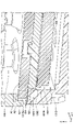
- FIG. 4 is a partially enlarged view of the switch device 100 shown in FIG.
- FIG. 5 is an external perspective view of the lower housing 130 included in the switch device 100 according to one embodiment.
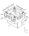
- FIG. 6 is an external perspective view of the lower housing 130 (with the substrate 160 placed thereon) included in the switch device 100 according to one embodiment.
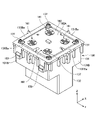
- FIG. 7 is an external perspective view of the lower housing 130 (with the substrate 160 and the rubber sheet 150 placed thereon) included in the switch device 100 according to one embodiment.
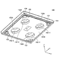
- FIG. 8 is an external perspective view of the rubber sheet 150 included in the switch device 100 according to one embodiment, viewed from the lower surface 150B side.
- FIG. 9 is a bottom view of the rubber sheet 150 included in the switch device 100 according to one embodiment.
- the base portion 131 of the lower housing 130 includes a bottom plate portion 131A provided parallel to the XY plane, and a bottom plate portion 131A that stands vertically upward (positive Z-axis direction) from the outer peripheral edge portion of the bottom plate portion 131A.
- the four side walls 131B With the four side walls 131B provided, it forms a substantially rectangular parallelepiped shape having an upper opening 131C and an internal space 131D.
- the side wall portion 131B extends in the Z-axis direction intersecting the XY plane direction of the substrate.
- the base 131 is housed inside the internal space 131D.
- a substrate 160 is stored inside the base portion 131, and the substrate 160 is supported by the lower housing 130 and arranged parallel to the bottom plate portion 131A.
- the four side walls 131B are arranged to surround the sides of the outer peripheral edge of the substrate 160 .
- Each of the four side wall portions 131B has an upper end surface 131Ba provided parallel to the XY plane.
- the bottom plate portion 131A of the base portion 131 is formed with an opening portion 134 and a drain port 135 penetrating through the bottom plate portion 131A in the vertical direction.
- the opening 134 communicates with the inside of the tube of the connector case 132, and a plurality of connector pins 162A of the connector 162 are inserted from above.
- the drain port 135 communicates with the inside of the connector case portion 132 so that water that has entered the internal space 131D of the lower housing 130 can be drained outside through the inside of the connector case portion 132 .
- a pedestal 136 is provided at each of the four inner corners of the internal space 131D in the base 131 of the lower housing 130.
- Each pedestal 136 has an upper surface 136A provided parallel to the XY plane at a constant height position.
- the top surface 136A is shaped to support the bottom surface of the substrate 160 .
- the vertical dimension from the upper surface 136A to the upper end surface 131Ba is the same as the dimension of the thickness of the substrate 160.
- each of the four corners of the substrate 160 is placed on the upper surface 136A of each of the four pedestals 136 . As a result, as shown in FIG.
- the substrate 160 is arranged such that the upper surface 160A of the substrate 160 is horizontal and the height position of the upper surface 160A is the same as the upper end surfaces 131Ba of the side wall portions 131B. can support Then, as shown in FIG. 6, the substrate 160 is placed inside the upper opening 131C in the base 131 of the lower housing 130, so that the upper opening 131C is closed by the substrate 160. As shown in FIG.
- a rubber sheet 150 is further placed on the lower housing 130 while the substrate 160 is placed thereon.
- the rectangular shape formed by the rubber sheet 150 is larger than the rectangular shape formed by the substrate 160 and equal to the rectangular shape formed by the outer shape of the base 131 of the lower housing 130 . Therefore, as shown in FIG. 7, the rubber sheet 150 is placed on the base portion 131 of the lower housing 130 so as to cover the entire upper surface 160A of the substrate 160 without protruding outside the base portion 131. can.
- each of the four corners of the base 131 is provided with a projection 137 projecting upward (positive direction of the Z-axis).
- Each of the four protrusions 137 engages with each of four recesses 153 (see FIG. 8) formed in the lower surface 150B of the rubber sheet 150, thereby accurately positioning the rubber sheet 150.
- FIG. 8 As shown in FIGS. 5 and 6, each of the four corners of the base 131 is provided with a projection 137 projecting upward (positive direction of the Z-axis).
- Each of the four protrusions 137 engages with each of four recesses 153 (see FIG. 8) formed in the lower surface 150B of the rubber sheet 150, thereby accurately positioning the rubber sheet 150.
- the base 151 of the rubber sheet 150 has a first area A1 overlapping the substrate 160 in plan view and a second area A2 outside the first area A1.
- the first area a1 has a substantially rectangular shape.
- the second area A2 has a substantially rectangular frame shape.
- the second area A2 is provided at a position overlapping the upper end surface 131Ba.
- the substrate 160, the upper end surface 131Ba, the first area A1, and the second area A2 are provided in a rectangular shape, but these have shapes that are related to each other. and the shape is not limited to a rectangle.
- the upper end surface 131Ba of the side wall portion 131B of the lower housing 130 is formed at the same height position as the upper surface 160A of the substrate 160. Further, as shown in FIG. 4 , at least a part of the second region A2 of the base portion 151 of the rubber sheet 150 (the portion overlapping the upper end surface 131Ba) is supported by the upper end surface 131Ba of the side wall portion 131B of the lower housing 130. be. That is, in the switch device 100 according to one embodiment, the substrate 160 can support the first region A1 of the base 151 of the rubber sheet 150 and the second region A1 of the base 151 of the rubber sheet 150 at the same height.
- the region A2 can be supported by the upper end surface 131Ba of the side wall portion 131B. Accordingly, in the switch device 100 according to one embodiment, the area of the substrate 160 can be made smaller than the area of the base 151 of the rubber sheet 150. , the miniaturization of the substrate 160 can be realized.
- the switch device 100 is arranged between the side wall portion 131B of the base portion 131 of the lower housing 130 and the side end surface 160C of the substrate 160 (that is, the outer peripheral edge portion of the substrate 160). and the inner peripheral edge of the upper opening 131C), a gap 131E is provided.
- a gap 131E is provided.
- the switch device 100 is provided with a drain port 135 in the bottom plate portion 131A (that is, below the gap 131E) of the lower housing 130. As shown in FIG. As a result, the switch device 100 according to one embodiment can drain water, which has been led to the internal space 131D from the gap 131E, to the outside through the drain port 135 and the interior of the connector case portion 132 . Therefore, the switch device 100 according to one embodiment can prevent the substrate 160 arranged in the internal space 131D from being flooded.
- the rubber sheet 150 is provided so as to protrude downward from the lower surface of the second area A2 and extend along the second area A2. It has an elastic protrusion 154 that extends (that is, has a rectangular frame shape in a plan view).
- the second area A2 of the rubber sheet 150 is formed between the pressing surface 112 of the upper housing 110 and the pressing surface 112 of the lower housing 130. It is sandwiched between the upper end surface 131Ba of the side wall portion 131B. At this time, as shown in FIG.
- the pressing surface 112 of the upper housing 110 presses the second area A2 of the rubber sheet 150 from above, thereby causing the second area A2 to move.
- the elastic protruding portion 154 provided on the lower surface of the lower housing 130 is pressed against the upper end surface 131Ba of the side wall portion 131B of the lower housing 130 .
- the upper end surface 131Ba of the side wall portion 131B of the lower housing 130 is formed in a rectangular frame shape surrounding the inner space 131D of the lower housing 130.
- the elastic protrusion 154 formed on the lower surface of the second region A2 of the rubber sheet 150 also has a rectangular frame shape that is in elastic contact with the rectangular frame-shaped upper end surface 131Ba over the entire circumference.
- the switch device 100 can prevent water from entering the internal space 131D, and can prevent the substrate 160 arranged in the internal space 131D from being flooded. .
- 100 switch device 100A housing 110 upper housing 110A lower opening 110B internal space 111 support 111A projection 111B opening 120 knob 120A internal space 121 rib 121A bearing hole 130 lower housing 131 base 131A bottom plate 131B side wall 131Ba top End surface 131C Upper opening 131D Internal space 131E Gap 132 Connector case portion 133 Engagement claw 134 Opening 135 Drain port 136 Base portion 136A Upper surface 137 Projection 140-1, 140-2 Slider 142-1, 142-2 Cam 150 Rubber sheet 151 Base 151A Upper surface 151B Lower surface A1 First area A2 Second area 152, 152-1, 152-2 Dome part 152A Movable contact 153 Recess 154 Elastic protrusion 160 Substrate 160A Upper surface 160B Lower surface 160C Side end surface 161 Fixed contact 162 Connector 162A Connector pin
Landscapes
- Tumbler Switches (AREA)
- Switch Cases, Indication, And Locking (AREA)
- Push-Button Switches (AREA)
Abstract
スイッチ装置は、操作力を受け付けるノブと、固定接点を有する基板と、可動接点を有し、ノブから伝達される操作力を受けて弾性変形することによって固定接点と可動接点とを接離可能に設けられるドーム部と、ドーム部の周囲に設けられドーム部を支持する基部とを有し、基板を覆って設けられるラバーシートと、基板およびラバーシートを格納する筐体とを備え、筐体は、上部筐体および下部筐体を有し、下部筐体の側壁部の上端面は、基板の上面と同じ高さ位置に形成され、基部は、平面視において基板と重なる第1領域と、第1領域よりも外側の第2領域とを有し、第2領域は、少なくとも一部が、上端面によって支持される。
Description
本発明は、スイッチ装置に関する。
従来、車両のパワーウインドウ等に使用されるスイッチ装置において、固定接点が設けられている基板と、可動接点と弾性変形可能なドーム部とを有するラバーシートと、を用いる技術が利用されている(例えば、下記特許文献1参照)。
ここで、ラバーシートのドーム部を設計通りに弾性変形させるためには、ドーム部と連続して設けられドーム部を支持するラバーシートの基部の面積を十分に大きくする必要がある。また更に、ラバーシートの基部と当接して基部を支持する支持面を基板の固定接点の周囲に設け、支持面の面積を十分に大きくする必要がある。しかしながら、従来のスイッチ装置は、ラバーシートの基部の全体を基板のみを用いて支持する構成だったため、基板の固定接点の周辺部の構成をスリム化することは困難だった。そのため、基板は小型化し難かった。なお、スイッチ装置の材料コストに対して、基板の材料コストが占める割合は比較的大きいため、コスト削減の観点から、基板を小型化するための技術が求められている。
一実施形態に係るスイッチ装置は、操作力を受け付けるノブと、固定接点を有する基板と、可動接点を有し、ノブから伝達される操作力を受けて弾性変形することによって固定接点と可動接点とを接離可能に設けられるドーム部と、ドーム部の周囲に設けられドーム部を支持する基部とを有し、基板を覆って設けられるラバーシートと、基板およびラバーシートを格納する筐体とを備え、筐体は、上部筐体および下部筐体を有し、下部筐体の側壁部の上端面は、基板の上面と同じ高さ位置に形成され、基部は、平面視において基板と重なる第1領域と、第1領域よりも外側の第2領域とを有し、第2領域は、少なくとも一部が、上端面によって支持される。
一実施形態によれば、ラバーシートの基部の面積を十分に確保しつつ、基板の小型化を実現することができる。
以下、図面を参照して、一実施形態について説明する。
(スイッチ装置100の概要)
図1は、一実施形態に係るスイッチ装置100の外観斜視図である。なお、以降の説明では、便宜上、X軸方向を前後方向とし、Y軸方向を左右方向とし、Z軸方向を上下方向とする。但し、X軸正方向を前方向とし、Y軸正方向を右方向とし、Z軸正方向を上方向とする。
図1は、一実施形態に係るスイッチ装置100の外観斜視図である。なお、以降の説明では、便宜上、X軸方向を前後方向とし、Y軸方向を左右方向とし、Z軸方向を上下方向とする。但し、X軸正方向を前方向とし、Y軸正方向を右方向とし、Z軸正方向を上方向とする。
図1に示すスイッチ装置100は、例えば、自動車等の車両に設置される車載装置(例えば、パワーウインドウ)の操作を行うためのスイッチ装置として利用することができる。スイッチ装置100は、傾倒操作可能なノブ120を備える。スイッチ装置100は、図1に示すように、ノブ120の中立状態において、スイッチオフ状態となる。また、スイッチ装置100は、操作者によってノブ120の前方(X軸正方向)または後方(X軸負方向)への傾倒操作がなされることにより、第1のスイッチオン状態または第2のスイッチオン状態に切り替わることができる。
(スイッチ装置100の構成)
図2は、一実施形態に係るスイッチ装置100の分解斜視図である。図3は、一実施形態に係るスイッチ装置100のYZ平面による断面を示す斜視断面図である。
図2は、一実施形態に係るスイッチ装置100の分解斜視図である。図3は、一実施形態に係るスイッチ装置100のYZ平面による断面を示す斜視断面図である。
図2に示すように、スイッチ装置100は、ノブ120、上部筐体110、2つのスライダ140-1,140-2、2つのカム142-1,142-2、ラバーシート150、基板160、および下部筐体130を備える。
ノブ120は、上部筐体110の上側(Z軸正側)に設けられている。ノブ120は、操作者からの操作力を受け付ける樹脂製の部材である。ノブ120は、上部筐体110が備える一対の突起部111Aによって、前方(X軸正方向)および後方(X軸負方向)へ傾倒可能に支持されている。図3に示すように、ノブ120は、下部が開口した中空構造を有する。また、図3に示すように、ノブ120の内部空間120Aには、左右に一対のリブ121が、当該内部空間120Aの天井面から垂下して設けられている。一対のリブ121の各々には、円形を有し、当該リブ121を左右方向に貫通する軸受孔121Aが形成されている。
上部筐体110は、概ね直方体形状且つ中空構造を有する容器状の部材である。上部筐体110は、樹脂製の部材である。上部筐体110は、筐体100Aの一部であり、下部筐体130と組み合わされることによって筐体100Aを構成する。上部筐体110の下部は、詳しくは後述する下部筐体130の基部131の側方を取り囲んで設けられる。上部筐体110と下部筐体130とによって構成される内部空間のうち、下部筐体130の基部131よりも高い位置には内部空間110Bが形成される。内部空間110Bには、2つのスライダ(140-1,140-2)、2つのカム(142-1,142-2)、4つのドーム部を有するラバーシート150、および基板160が収容される。上部筐体110の上部には、上下方向に延設された略四角筒状の外形を有する支持部111が形成されている。支持部111のノブ120側には、組立後には、組立後にはノブ120によって閉塞される開口111Bが形成されている。図2および図3に示すように、支持部111は、壁部111Cの左右両方の内壁面から右方向または左方向に突出して形成された一対の突起部111Aを有する。突起部111Aは、ノブ120の軸受孔121Aに対応した形状を有し、軸受孔121Aに対応した位置に設けられている。図3に示すように、組立後、一対の突起部111Aの各々が対応する軸受孔121Aに係合することによって、支持部111はノブ120を支持する。また、ノブ120は前後方向(X軸方向)に傾倒可能に支持される。
2つのスライダ140-1,140-2は、上部筐体110の内部空間110Bにおいて、前後方向(X軸方向)に並んだ状態で、上下方向(Z軸方向)にスライド可能に設けられる。カム142-1,142-2は、上部筐体110の内部において、前後方向(X軸方向)に並んだ状態で、スライダ140-1,140-2と、ラバーシート150との間に配置される。スライダ140-1、及び、カム142-1は、ノブ120が前方向(X軸正方向)に傾倒したとき、ノブ120の傾倒に合わせて動作する部材である。スライダ140-2、及び、カム142-2は、ノブ120が後方向(X軸負方向)に傾倒したとき、ノブ120の傾倒に合わせて動作する部材である。
カム142-1は、内部空間110Bの前側(X軸正側)に配置される部材である。カム142-1は、左右方向(Y軸方向)に長手形状を有する樹脂製の部材である。カム142-1の上方にはスライダ140-1が配置され、カム142-1とスライダ140-1とは接して設けられる。カム142-1の下方には、ラバーシート150の前側に形成された2つのドーム部152-1が配置される。カム142-1は、2つのドーム部152-1の各々の頂部に懸架されて配置される。カム142-1は、上面の中央を基準として左方向(Y軸負方向)に寄った位置から上方に突出して設けられた突起部142Aを有している。突起部142Aの頂部は、前側(X軸正側)のスライダ140-1の下面に当接している。ノブ120の前方(X軸正方向)への傾倒操作がなされたとき、カム142-1はスライダ140-1によって突起部142Aが押圧される。突起部142Aは左方向に偏った位置に設けられていることによって、カム142-1の左方側に伝達される押圧力と、カム142-1の右方側に伝達される押圧力と、は不均等になる。そのため、カム142-1は、弾性変形する2つのドーム部152-1に支持されながら、YZ平面と平行なストロークで揺動する。
スライダ140-1は、内部空間110Bの前側(X軸正側)に配置される部材である。スライダ140-1は、上部筐体110によってガイドされており、X軸方向及びY軸方向へは移動出来ないように規制され、Z軸方向にスライド出来るように設けられている。スライダ140-1は、ノブ120の前方(X軸正方向)への傾倒操作がなされたときに、ノブ120によって押し下げられ、下方へスライドする。これにより、スライダ140-1は、カム142-1の突起部142Aを押し下げる。突起部142Aを押し下げられたカム142-1は、YZ平面と平行なストロークで揺動し、ドーム部152-1の頂点を押し下げる。図3に示すようにカム142-1の突起部142Aは左方向に偏った位置に設けられているため、突起部142Aを押し下げられたカム142-1は、左方向に揺動し、右側のドーム部152-1より先に左側のドーム部152-1を押し下げて弾性変形させる。その後、更に突起部142Aが押し下げられた場合、カム142-1は左側のドーム部152-1の頂部を支点として右方向に揺動し、右側のドーム部152-1を押し下げて弾性変形させる。
本実施形態において、ドーム部152-1と連続してドーム部152-1の周囲に設けられる基部151は、十分大きな寸法を有して基部151自身は変形し難くするために基部151の下面151Bは基板160および上端面131Baに接している。それにより、頂点を押し下げられたドーム部152-1は、設計通りに弾性変形し、一部が反転する。これにより、一実施形態に係るスイッチ装置100は、第1のスイッチオン状態に2段階で切り替わる。なお、ノブ120の前方(X軸正方向)への傾倒操作が解除された時、2つのドーム部152-1は復帰する。また、当該2つのドーム部152-1からの復帰力によって、カム142-1とスライダ140-1とノブ120とは中立状態に復帰する。基部151と上端面131Baとの詳細については後述する。
カム142-2は、内部空間110Bの後側(X軸負側)に配置される部材である。カム142-2は、左右方向(Y軸方向)に長手形状を有する樹脂製の部材である。カム142-2の上方にはスライダ140-2が配置され、カム142-2とスライダ140-2とは接して設けられる。カム142-2の下方には、ラバーシート150の前側に形成された2つのドーム部152-2が配置される。カム142-2は、2つのドーム部152-2の各々の頂部に懸架されて配置される。カム142-2は、上面の中央を基準として左方向(Y軸負方向)に寄った位置から上方に突出して設けられた突起部142Aを有している。突起部142Aの頂部は、後側(X軸負側)のスライダ140-2の下面に当接している。ノブ120の後方(X軸負方向)への傾倒操作がなされたとき、カム142-2はスライダ140-2によって突起部142Aが押圧される。突起部142Aは左方向に偏った位置に設けられていることによって、カム142-2の左方側に伝達される押圧力と、カム142-2の右方側に伝達される押圧力と、は不均等になる。そのため、カム142-2は、弾性変形する2つのドーム部152-2に支持されながら、YZ平面と平行なストロークで揺動する。
スライダ140-2は、内部空間110Bの後側(X軸負側)に配置される部材である。スライダ140-2は、上部筐体110によってガイドされており、X軸方向及びY軸方向へは移動出来ないように規制され、Z軸方向にスライド出来るように設けられている。スライダ140-2は、ノブ120の後方(X軸負方向)への傾倒操作がなされたときに、ノブ120によって押し下げられ、下方へスライドする。これにより、スライダ140-2は、カム142-2の突起部142Aを押し下げる。突起部142Aを押し下げられたカム142-2は、YZ平面と平行なストロークで揺動し、ドーム部152-2の頂点を押し下げる。図3に示すようにカム142-2の突起部142Aは左方向に偏った位置に設けられているため、突起部142Aを押し下げられたカム142-2は、左方向に揺動し、右側のドーム部152-2より先に左側のドーム部152-2を押し下げて弾性変形させる。その後、更に突起部142Aが押し下げられた場合、カム142-2は左側のドーム部152-2の頂部を支点として右方向に揺動し、右側のドーム部152-2を押し下げて弾性変形させる。
本実施形態において、ドーム部152-2と連続してドーム部152-2の周囲に設けられる基部151は、十分大きな寸法を有して基部151自身は変形し難くするために、基部151の下面151Bは基板160および上端面131Baに接している。それにより、頂点を押し下げられたドーム部152-2は、設計通りに弾性変形し、一部が反転する。これにより、一実施形態に係るスイッチ装置100は、第2のスイッチオン状態に2段階で切り替わる。なお、ノブ120の後方(X軸負方向)への傾倒操作が解除された時、2つのドーム部152-2は復帰する。また、当該2つのドーム部152-2からの復帰力によって、カム142-2とスライダ140-2とノブ120とは中立状態に復帰する。
基板160は、硬質な樹脂製且つ平板状の部材である。基板160は、XY平面方向と平行に設けられている。基板160は、筐体100Aの内部に格納されている。基板160は、平面視において四角形状を有する。基板160は、上部筐体110の内部空間110Bにおいて、XY平面に対して平行な姿勢で配置される。基板160としては、例えば、PWB(Printed Wiring Board)が用いられる。
基板160の上面160Aには、いずれも平面視において概ね円形状を有する4つの固定接点161が、2×2のマトリクス状に配設されている。各固定接点161は、薄板状の金属素材(例えば、銅膜)が用いられて形成されている。
基板160の下面160Bには、コネクタ162が設けられている。コネクタ162は、左右方向(Y軸方向)に並べて設けられた、複数本のコネクタピン162Aを有する。各コネクタピン162Aは、基板160の下面160Bに対して垂直に設けられる、金属製且つ棒状の部材である。
ラバーシート150は、弾性素材(例えば、シリコン、ゴム等)が用いられて形成される平板状の部材である。ラバーシート150は、基板160を覆って設けられる部材である。ラバーシート150は、平面視において、基板160よりも大きい四角形状を有する。すなわち、ラバーシート150の一辺の長さは、基板160の一辺の長さよりも大きくなっている。ラバーシート150は、詳しくは後述する基部151の一部が基板160の上面160Aに当接して配置される。そのため、ラバーシート150は、上部筐体110の内部空間110Bにおいて、XY平面に対して平行な姿勢で配置される。ラバーシート150が基板160を覆って設けられていることにより、基板160は上部筐体110の開口111Bから侵入する水滴等から保護される。
ラバーシート150は、基部151と、4つのドーム部152とを有する。基部151は、水平な平板状の部分であり、平面視において矩形状を有する。基部151は、4つのドーム部152を支持する。4つのドーム部152は、基部151の上面151Aよりも上方に突出して設けられたドーム状を有する。4つのドーム部152の各々は、平面視において基板160の4つの固定接点161の各々と重なる位置に設けられている。すなわち、ラバーシート150において、4つのドーム部152は、2×2のマトリクス状に配設されている。ドーム部152の下方側(Z軸負方向側)の面には可動接点152Aが設けられている。各ドーム部152は、ノブ120の傾倒操作がなされたときに、当該ドーム部152の上側(Z軸正側)に配置されているカム142によって押し下げられることにより、下方(Z軸負方向)に屈曲(弾性変形)して、当該ドーム部152の下側(Z軸負側)に配置されている固定接点161と接触する。このとき、当該固定接点161と可動接点152Aとが接触して導通状態になる。ドーム部152は復帰力を有しており、操作力から開放された時、初期状態に復帰する。
下部筐体130は、上部筐体110の下側開口部110Aを閉塞する、樹脂製の部材である。下部筐体130は、上部筐体110とともに、筐体100Aを構成する。下部筐体130は、概ね直方体形状且つ中空構造を有する、基部131を備える。基部131は、上部筐体110の下側開口部110Aから、上部筐体110の内部空間110Bに嵌め込まれることにより、上部筐体110の下側開口部110Aを閉塞する。基部131の側面には、複数の係合爪133が設けられている。基部131は、複数の係合爪133が、上部筐体110の内部空間110Bの内壁面に係合することにより、上部筐体110の下側開口部110Aを閉塞した状態で上部筐体110に固定される。基部131の上部開口131C内には、基板160が載置される。これにより、基部131の上部開口131Cは、基板160によって閉塞される。
また、下部筐体130は、基部131の底面から下方(Z軸負方向)に突出して設けられた、四角筒状のコネクタケース部132を有する。コネクタケース部132の内部には、基部131の底板部131Aに形成されている開口部134から差し込まれた、複数のコネクタピン162Aが配設される。コネクタケース部132は、外部コネクタ(図示省略)が嵌め合わされることにより、複数のコネクタピン162Aを、外部コネクタに接続させることができる。
(下部筐体130およびラバーシート150の構成)
図4は、図3に示すスイッチ装置100の一部拡大図である。図5は、一実施形態に係るスイッチ装置100が備える下部筐体130の外観斜視図である。図6は、一実施形態に係るスイッチ装置100が備える下部筐体130(基板160が載置された状態)の外観斜視図である。図7は、一実施形態に係るスイッチ装置100が備える下部筐体130(基板160およびラバーシート150が載置された状態)の外観斜視図である。図8は、一実施形態に係るスイッチ装置100が備えるラバーシート150の下面150B側から見た外観斜視図である。図9は、一実施形態に係るスイッチ装置100が備えるラバーシート150の下面図である。
図4は、図3に示すスイッチ装置100の一部拡大図である。図5は、一実施形態に係るスイッチ装置100が備える下部筐体130の外観斜視図である。図6は、一実施形態に係るスイッチ装置100が備える下部筐体130(基板160が載置された状態)の外観斜視図である。図7は、一実施形態に係るスイッチ装置100が備える下部筐体130(基板160およびラバーシート150が載置された状態)の外観斜視図である。図8は、一実施形態に係るスイッチ装置100が備えるラバーシート150の下面150B側から見た外観斜視図である。図9は、一実施形態に係るスイッチ装置100が備えるラバーシート150の下面図である。
図5に示すように、下部筐体130の基部131は、XY平面に対して平行に設けられた底板部131Aと、底板部131Aの外周縁部から上方(Z軸正方向)に垂直に立設された4つの側壁部131Bとにより、上部開口131Cおよび内部空間131Dを有する、概ね直方体形状をなす。図3、図4に示すように、側壁部131Bは、基板のなすXY平面方向と交差するZ軸方向に延設されている。基部131は内部空間131Dの内部に格納される。基部131の内部には基板160が格納されており、基板160は、下部筐体130によって支持されて底板部131Aと平行に配置される。4つの側壁部131Bは基板160の外周縁部の側方を取り囲んで配置される。4つの側壁部131Bの各々は、XY平面と平行に設けられた上端面131Baを有する。また、図5に示すように、基部131の底板部131Aには、当該底板部131Aを上下方向に貫通する、開口部134および排水口135が形成されている。開口部134は、コネクタケース部132の筒内に通じており、上方からコネクタ162が備える複数のコネクタピン162Aが挿通される。排水口135は、コネクタケース部132の筒内に通じており、下部筐体130の内部空間131Dに浸入した水を、コネクタケース部132の筒内を介して、外部へ排水することができる。
図5に示すように、下部筐体130の基部131における内部空間131Dの4つの内角部の各々には、台座部136が設けられている。各台座部136は、一定の高さ位置に、XY平面と平行に設けられた上面136Aを有する。上面136Aは、基板160の下面を支持するために設けられる形状である。上下方向における上面136Aから上端面131Baまでの寸法は、基板160の厚さの寸法と同一にされている。図6に示すように、4つの台座部136の各々の上面136Aには、基板160の4つの角部の各々が載置される。これにより、図6に示すように、基板160の上面160Aが水平となり、且つ、上面160Aの高さ位置が、側壁部131Bの各々の上端面131Baと同じ高さ位置となるように、基板160を支持することができる。そして、図6に示すように、下部筐体130の基部131における上部開口131Cの内側に、基板160が載置されることにより、上部開口131Cが基板160によって閉塞される。
図7に示すように、下部筐体130には、基板160が載置された状態で、さらにラバーシート150が載置される。ラバーシート150がなす矩形状は、基板160がなす矩形状よりも大きく、且つ、下部筐体130の基部131の外形状がなす矩形状と等しい。このため、図7に示すように、ラバーシート150は、下部筐体130の基部131に載置されることにより、基部131から外側へはみ出すことなく、基板160の上面160Aの全体を覆うことができる。
なお、図5および図6に示すように、基部131の4つの角部の各々には、上方(Z軸正方向)に突出した突起137が設けられている。4つの突起137の各々は、ラバーシート150の下面150Bに形成された4つの凹部153(図8参照)の各々に係合することにより、ラバーシート150を正確に位置決めすることができる。
図9に示すように、ラバーシート150の基部151は、平面視において基板160と重なる第1領域A1と、第1領域A1よりも外側の第2領域A2とを有する。第1領域a1は、概ね矩形状である。第2領域A2は、概ね矩形枠状である。第2領域A2は、上端面131Baと重なる位置に設けられている。尚、本実施形態において、基板160及び上端面131Ba及び第1領域A1及び第2領域A2は、矩形状を有して設けられているが、これらは、互いに関連性の有る形状を有していれば良く、その形状は矩形に限らない。
図4に示すように、一実施形態に係るスイッチ装置100において、下部筐体130の側壁部131Bの上端面131Baは、基板160の上面160Aと同じ高さ位置に形成されている。また、図4に示すように、ラバーシート150の基部151の第2領域A2は、少なくとも一部(上端面131Baと重なる部分)が、下部筐体130の側壁部131Bの上端面131Baによって支持される。すなわち、一実施形態に係るスイッチ装置100は、同じ高さ位置で、ラバーシート150の基部151の第1領域A1を、基板160によって支持することができるとともに、ラバーシート150の基部151の第2領域A2を、側壁部131Bの上端面131Baによって支持することができる。これにより、一実施形態に係るスイッチ装置100は、基板160の面積をラバーシート150の基部151の面積よりも小さくすることができ、よって、ラバーシート150の基部151の面積を十分に確保しつつ、基板160の小型化を実現することができる。
また、図4に示すように、一実施形態に係るスイッチ装置100は、下部筐体130の基部131の側壁部131Bと、基板160の側端面160Cとの間(すなわち、基板160の外周縁部と、上部開口131Cの内周縁部との間)に、隙間131Eが設けられている。これにより、一実施形態に係るスイッチ装置100は、万が一、毛細管現象等によって、側壁部131Bの上端面131Baと、ラバーシート150の基部151の第2領域A2との間から、水が浸入した場合であっても、当該水を隙間131Eから、内部空間131Dにおける基板160の下方へ導くことができる。したがって、一実施形態に係るスイッチ装置100は、内部空間131Dに配置された基板160が浸水してしまうことを抑制することができる。
また、図4に示すように、一実施形態に係るスイッチ装置100は、下部筐体130における底板部131A(すなわち、隙間131Eよりも下方)に、排水口135が設けられている。これにより、一実施形態に係るスイッチ装置100は、隙間131Eから内部空間131Dに導かれた水を、排水口135から、コネクタケース部132の筒内を介して、外部へ排水することができる。したがって、一実施形態に係るスイッチ装置100は、内部空間131Dに配置された基板160が浸水してしまうことを抑制することができる。
また、図8および図9に示すように、一実施形態に係るスイッチ装置100において、ラバーシート150は、第2領域A2の下面から下方に突出して設けられ、且つ、第2領域A2に沿って延設された(すなわち、平面視において矩形枠状の)弾性突起部154を有する。図4に示すように、上部筐体110と下部筐体130とが組み合わされたときに、ラバーシート150の第2の領域A2は、上部筐体110の押圧面112と、下部筐体130の側壁部131Bの上端面131Baとの間で挟持される。この際、図4に示すように、上部筐体110の押圧面112は、ラバーシート150の第2の領域A2の上方から、当該第2領域A2を押圧することにより、当該第2の領域A2の下面に設けられた弾性突起部154を、下部筐体130の側壁部131Bの上端面131Baに押し当てる。ここで、下部筐体130の側壁部131Bの上端面131Baは、下部筐体130の内部空間131Dを取り囲む矩形枠状に形成されている。これに対し、ラバーシート150の第2の領域A2の下面に形成されている弾性突起部154も、矩形枠状の上端面131Baに対して全周に亘って弾接する矩形枠状を有する。これにより、下部筐体130の内部空間131Dは、当該内部空間131Dを取り囲むように矩形枠状に延設された弾性突起部154によって密閉される。その結果、一実施形態に係るスイッチ装置100は、内部空間131Dに水が浸入することを抑制することができ、内部空間131Dに配置された基板160が浸水してしまうことを抑制することができる。
以上、本発明の一実施形態について詳述したが、本発明はこれらの実施形態に限定されるものではなく、特許請求の範囲に記載された本発明の要旨の範囲内において、種々の変形又は変更が可能である。
本国際出願は、2021年2月19日に出願した日本国特許出願第2021-025521号に基づく優先権を主張するものであり、当該出願の全内容を本国際出願に援用する。
100 スイッチ装置
100A 筐体
110 上部筐体
110A 下側開口部
110B 内部空間
111 支持部
111A 突起部
111B 開口
120 ノブ
120A 内部空間
121 リブ
121A 軸受孔
130 下部筐体
131 基部
131A 底板部
131B 側壁部
131Ba 上端面
131C 上部開口
131D 内部空間
131E 隙間
132 コネクタケース部
133 係合爪
134 開口部
135 排水口
136 台座部
136A 上面
137 突起
140-1,140-2 スライダ
142-1,142-2 カム
150 ラバーシート
151 基部
151A 上面
151B 下面
A1 第1領域
A2 第2領域
152,152-1,152-2 ドーム部
152A 可動接点
153 凹部
154 弾性突起部
160 基板
160A 上面
160B 下面
160C 側端面
161 固定接点
162 コネクタ
162A コネクタピン
100A 筐体
110 上部筐体
110A 下側開口部
110B 内部空間
111 支持部
111A 突起部
111B 開口
120 ノブ
120A 内部空間
121 リブ
121A 軸受孔
130 下部筐体
131 基部
131A 底板部
131B 側壁部
131Ba 上端面
131C 上部開口
131D 内部空間
131E 隙間
132 コネクタケース部
133 係合爪
134 開口部
135 排水口
136 台座部
136A 上面
137 突起
140-1,140-2 スライダ
142-1,142-2 カム
150 ラバーシート
151 基部
151A 上面
151B 下面
A1 第1領域
A2 第2領域
152,152-1,152-2 ドーム部
152A 可動接点
153 凹部
154 弾性突起部
160 基板
160A 上面
160B 下面
160C 側端面
161 固定接点
162 コネクタ
162A コネクタピン
Claims (7)
- 操作力を受け付けるノブと、
固定接点を有する基板と、
可動接点を有し、前記ノブから伝達される操作力を受けて弾性変形することによって前記固定接点と前記可動接点とを接離可能に設けられるドーム部と、前記ドーム部の周囲に設けられ前記ドーム部を支持する基部とを有し、前記基板を覆って設けられるラバーシートと、
前記基板および前記ラバーシートを格納する筐体と
を備え、
前記筐体は、上部筐体および下部筐体を有し、
前記下部筐体の側壁部の上端面は、前記基板の上面と同じ高さ位置に形成され、
前記基部は、平面視において前記基板と重なる第1領域と、前記第1領域よりも外側の第2領域とを有し、
前記第2領域は、少なくとも一部が、前記上端面によって支持される
ことを特徴とするスイッチ装置。 - 前記基板は、前記下部筐体に格納されている
ことを特徴とする請求項1に記載のスイッチ装置。 - 前記側壁部は、前記基板のなす平面方向と交差する方向に延設され、平面視において、前記基板の外周縁部を囲んで設けられている
ことを特徴とする請求項1または請求項2に記載のスイッチ装置。 - 平面視において、前記上端面は前記基板の外周縁部よりも外側に配置されている
ことを特徴とする請求項1から3のいずれか一項に記載のスイッチ装置。 - 前記側壁部と前記基板との間に隙間が設けられている
ことを特徴とする請求項1から4のいずれか一項に記載のスイッチ装置。 - 前記下部筐体は、
前記隙間よりも下方に排水口が設けられている
ことを特徴とする請求項5に記載のスイッチ装置。 - 前記ラバーシートは、
第2領域の下面から下方に突出して設けられ、且つ、前記第2領域に沿って延設された弾性突起部を有し、
前記上部筐体は、
前記第2領域の上方から前記第2領域を押圧することにより、前記弾性突起部を前記上端面に押し当てる押圧面を有する
ことを特徴とする請求項1から6のいずれか一項に記載のスイッチ装置。
Applications Claiming Priority (2)
| Application Number | Priority Date | Filing Date | Title |
|---|---|---|---|
| JP2021025521A JP2024049404A (ja) | 2021-02-19 | 2021-02-19 | スイッチ装置 |
| JP2021-025521 | 2021-02-19 |
Publications (1)
| Publication Number | Publication Date |
|---|---|
| WO2022176325A1 true WO2022176325A1 (ja) | 2022-08-25 |
Family
ID=82931336
Family Applications (1)
| Application Number | Title | Priority Date | Filing Date |
|---|---|---|---|
| PCT/JP2021/044828 Ceased WO2022176325A1 (ja) | 2021-02-19 | 2021-12-07 | スイッチ装置 |
Country Status (2)
| Country | Link |
|---|---|
| JP (1) | JP2024049404A (ja) |
| WO (1) | WO2022176325A1 (ja) |
Citations (4)
| Publication number | Priority date | Publication date | Assignee | Title |
|---|---|---|---|---|
| JPH09185921A (ja) * | 1995-12-28 | 1997-07-15 | Yazaki Corp | スイッチの排水構造 |
| JPH1173838A (ja) * | 1997-08-28 | 1999-03-16 | Kouha:Kk | 照光式押し釦 |
| JP2001187968A (ja) * | 1999-12-28 | 2001-07-10 | Shin Etsu Polymer Co Ltd | 電気電子機器用のガスケット |
| JP2001210190A (ja) * | 1999-12-21 | 2001-08-03 | Leopold Kostal Gmbh & Co Kg | 電気的スイッチ |
-
2021
- 2021-02-19 JP JP2021025521A patent/JP2024049404A/ja active Pending
- 2021-12-07 WO PCT/JP2021/044828 patent/WO2022176325A1/ja not_active Ceased
Patent Citations (4)
| Publication number | Priority date | Publication date | Assignee | Title |
|---|---|---|---|---|
| JPH09185921A (ja) * | 1995-12-28 | 1997-07-15 | Yazaki Corp | スイッチの排水構造 |
| JPH1173838A (ja) * | 1997-08-28 | 1999-03-16 | Kouha:Kk | 照光式押し釦 |
| JP2001210190A (ja) * | 1999-12-21 | 2001-08-03 | Leopold Kostal Gmbh & Co Kg | 電気的スイッチ |
| JP2001187968A (ja) * | 1999-12-28 | 2001-07-10 | Shin Etsu Polymer Co Ltd | 電気電子機器用のガスケット |
Also Published As
| Publication number | Publication date |
|---|---|
| JP2024049404A (ja) | 2024-04-10 |
Similar Documents
| Publication | Publication Date | Title |
|---|---|---|
| JP4075608B2 (ja) | プッシュオンスイッチ | |
| JP2001210176A (ja) | プッシュオンスイッチおよびそれを装着した電子機器、ならびにその装着方法 | |
| KR100477775B1 (ko) | 다방향 스위치장치 | |
| WO2019187343A1 (ja) | スイッチ装置 | |
| JP2004171924A (ja) | 多方向スライドスイッチ | |
| US6459058B1 (en) | Operating device having operating button adapted to slide in housing while being pushed to effect switching operation | |
| JP2003045291A (ja) | 操作ボタン構造 | |
| JP2024049404A (ja) | スイッチ装置 | |
| US12482616B2 (en) | Input device | |
| JP5428890B2 (ja) | プッシュオンスイッチ | |
| CN111525351B (zh) | 电连接器 | |
| JP2022043622A (ja) | プッシュスイッチ | |
| JP2022163240A (ja) | 構造体 | |
| JP4407441B2 (ja) | プッシュオンスイッチ | |
| JP2025184474A (ja) | スイッチ装置及びスイッチ装置の組み立て方法 | |
| JP3900607B2 (ja) | プッシュオンスイッチ | |
| JP7511495B2 (ja) | 筐体および電子機器 | |
| JP2000294079A (ja) | プッシュオンスイッチ | |
| JP4201682B2 (ja) | 二段押圧スイッチ | |
| JP2003123596A (ja) | 多方向操作スイッチおよびこれを用いた多方向操作装置 | |
| JP2005019314A (ja) | 多方向押圧型スイッチ | |
| CN120020986A (zh) | 按压开关 | |
| JP4343058B2 (ja) | スイッチおよびその組み立て方法 | |
| JP2003077363A (ja) | キースイッチ | |
| JP2020071991A (ja) | スイッチモジュール、及び、スイッチ装置 |
Legal Events
| Date | Code | Title | Description |
|---|---|---|---|
| 121 | Ep: the epo has been informed by wipo that ep was designated in this application |
Ref document number: 21926065 Country of ref document: EP Kind code of ref document: A1 |
|
| NENP | Non-entry into the national phase |
Ref country code: DE |
|
| 122 | Ep: pct application non-entry in european phase |
Ref document number: 21926065 Country of ref document: EP Kind code of ref document: A1 |
|
| NENP | Non-entry into the national phase |
Ref country code: JP |