WO2022176260A1 - スピーカ装置 - Google Patents
スピーカ装置 Download PDFInfo
- Publication number
- WO2022176260A1 WO2022176260A1 PCT/JP2021/037250 JP2021037250W WO2022176260A1 WO 2022176260 A1 WO2022176260 A1 WO 2022176260A1 JP 2021037250 W JP2021037250 W JP 2021037250W WO 2022176260 A1 WO2022176260 A1 WO 2022176260A1
- Authority
- WO
- WIPO (PCT)
- Prior art keywords
- vibrating body
- actuator
- vibration
- speaker device
- vibrating
- Prior art date
- Legal status (The legal status is an assumption and is not a legal conclusion. Google has not performed a legal analysis and makes no representation as to the accuracy of the status listed.)
- Ceased
Links
Images



Classifications
-
- H—ELECTRICITY
- H04—ELECTRIC COMMUNICATION TECHNIQUE
- H04R—LOUDSPEAKERS, MICROPHONES, GRAMOPHONE PICK-UPS OR LIKE ACOUSTIC ELECTROMECHANICAL TRANSDUCERS; ELECTRIC HEARING AIDS; PUBLIC ADDRESS SYSTEMS
- H04R7/00—Diaphragms for electromechanical transducers; Cones
- H04R7/02—Diaphragms for electromechanical transducers; Cones characterised by the construction
- H04R7/04—Plane diaphragms
- H04R7/045—Plane diaphragms using the distributed mode principle, i.e. whereby the acoustic radiation is emanated from uniformly distributed free bending wave vibration induced in a stiff panel and not from pistonic motion
-
- F—MECHANICAL ENGINEERING; LIGHTING; HEATING; WEAPONS; BLASTING
- F21—LIGHTING
- F21S—NON-PORTABLE LIGHTING DEVICES; SYSTEMS THEREOF; VEHICLE LIGHTING DEVICES SPECIALLY ADAPTED FOR VEHICLE EXTERIORS
- F21S8/00—Lighting devices intended for fixed installation
- F21S8/04—Lighting devices intended for fixed installation intended only for mounting on a ceiling or the like overhead structures
-
- F—MECHANICAL ENGINEERING; LIGHTING; HEATING; WEAPONS; BLASTING
- F21—LIGHTING
- F21V—FUNCTIONAL FEATURES OR DETAILS OF LIGHTING DEVICES OR SYSTEMS THEREOF; STRUCTURAL COMBINATIONS OF LIGHTING DEVICES WITH OTHER ARTICLES, NOT OTHERWISE PROVIDED FOR
- F21V33/00—Structural combinations of lighting devices with other articles, not otherwise provided for
-
- H—ELECTRICITY
- H04—ELECTRIC COMMUNICATION TECHNIQUE
- H04R—LOUDSPEAKERS, MICROPHONES, GRAMOPHONE PICK-UPS OR LIKE ACOUSTIC ELECTROMECHANICAL TRANSDUCERS; ELECTRIC HEARING AIDS; PUBLIC ADDRESS SYSTEMS
- H04R1/00—Details of transducers, loudspeakers or microphones
- H04R1/02—Casings; Cabinets ; Supports therefor; Mountings therein
- H04R1/025—Arrangements for fixing loudspeaker transducers, e.g. in a box, furniture
-
- H—ELECTRICITY
- H04—ELECTRIC COMMUNICATION TECHNIQUE
- H04R—LOUDSPEAKERS, MICROPHONES, GRAMOPHONE PICK-UPS OR LIKE ACOUSTIC ELECTROMECHANICAL TRANSDUCERS; ELECTRIC HEARING AIDS; PUBLIC ADDRESS SYSTEMS
- H04R1/00—Details of transducers, loudspeakers or microphones
- H04R1/02—Casings; Cabinets ; Supports therefor; Mountings therein
- H04R1/028—Casings; Cabinets ; Supports therefor; Mountings therein associated with devices performing functions other than acoustics, e.g. electric candles
-
- H—ELECTRICITY
- H04—ELECTRIC COMMUNICATION TECHNIQUE
- H04R—LOUDSPEAKERS, MICROPHONES, GRAMOPHONE PICK-UPS OR LIKE ACOUSTIC ELECTROMECHANICAL TRANSDUCERS; ELECTRIC HEARING AIDS; PUBLIC ADDRESS SYSTEMS
- H04R1/00—Details of transducers, loudspeakers or microphones
- H04R1/20—Arrangements for obtaining desired frequency or directional characteristics
- H04R1/22—Arrangements for obtaining desired frequency or directional characteristics for obtaining desired frequency characteristic only
- H04R1/28—Transducer mountings or enclosures modified by provision of mechanical or acoustic impedances, e.g. resonator, damping means
- H04R1/2803—Transducer mountings or enclosures modified by provision of mechanical or acoustic impedances, e.g. resonator, damping means for loudspeaker transducers
-
- H—ELECTRICITY
- H04—ELECTRIC COMMUNICATION TECHNIQUE
- H04R—LOUDSPEAKERS, MICROPHONES, GRAMOPHONE PICK-UPS OR LIKE ACOUSTIC ELECTROMECHANICAL TRANSDUCERS; ELECTRIC HEARING AIDS; PUBLIC ADDRESS SYSTEMS
- H04R2420/00—Details of connection covered by H04R, not provided for in its groups
- H04R2420/07—Applications of wireless loudspeakers or wireless microphones
-
- H—ELECTRICITY
- H04—ELECTRIC COMMUNICATION TECHNIQUE
- H04R—LOUDSPEAKERS, MICROPHONES, GRAMOPHONE PICK-UPS OR LIKE ACOUSTIC ELECTROMECHANICAL TRANSDUCERS; ELECTRIC HEARING AIDS; PUBLIC ADDRESS SYSTEMS
- H04R9/00—Transducers of moving-coil, moving-strip, or moving-wire type
- H04R9/02—Details
- H04R9/04—Construction, mounting, or centering of coil
- H04R9/046—Construction
Definitions
- the present disclosure relates to a speaker device.
- Patent Document 1 discloses a lighting fixture that includes a light source, a speaker unit that is arranged on the side opposite to the light emitting direction with respect to the light source, and a fixture body that houses the light source and the speaker unit.
- This lighting fixture is, for example, a lighting fixture called a downlight, which is embedded in a mounting hole provided in the ceiling of a building, etc., and directs the light from the light source and the sound from the speaker unit downward (such as the floor). ) can be output.
- the present disclosure provides a speaker device that is spatially efficient and capable of outputting sound over a wide range.
- a speaker device includes a main body attached to a predetermined position, a first actuator housed in the main body and generating vibration according to an input audio signal, and vibrating due to vibration transmitted from the outside. and a string-like or rod-like first vibration transmitting member that transmits vibrations generated by the first actuator to the vibrating body, wherein the vibrating body is transmitted by the first vibration transmitting member to the first vibration transmitting member. It is arranged in a suspended form from one actuator.
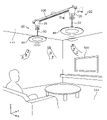
- FIG. 1 is a perspective view showing an installation example of a speaker device according to an embodiment.
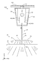
- FIG. 2 is a cross-sectional view showing the outline of the internal configuration of the main body of the speaker device according to the embodiment.
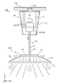
- FIG. 3 is a diagram showing the outline of the configuration of the actuator according to the embodiment.
- FIG. 4 is a diagram showing a schematic configuration of a speaker device according to Modification 1 of the embodiment.
- FIG. 5 is a diagram showing a schematic configuration of a speaker device according to Modification 2 of the embodiment.
- FIG. 6 is a diagram showing a schematic configuration of a speaker device according to Modification 3 of the embodiment.
- a speaker device including a speaker unit and a box-shaped enclosure to which the speaker unit is fixed.
- this conventional speaker device is arranged in a room such as a living room, the speaker device may be fixed to the ceiling.
- the speaker device can be placed indoors without consuming floor space.
- a new speaker device placed in an upper space in a room may give a sense of oppression or discomfort to people in the room.
- a lighting fixture with a built-in speaker unit such as the conventional lighting fixture, an existing adapter or the like for the lighting fixture provided on the ceiling is used to attach a device that outputs sound to the ceiling. can be placed.
- a lighting fixture with a built-in speaker unit appears to be a general lighting fixture, so its presence is less likely to give a sense of oppression or discomfort to people in the room.
- the vertical direction is aligned with the Z-axis direction
- the front-back direction is aligned with the Y-axis direction
- the left-right direction is aligned with the X-axis direction.
- these associations do not limit the posture during manufacture or use of the speaker device according to the present disclosure.
- the positive direction of the X-axis indicates the arrow direction of the X-axis
- the negative direction of the X-axis indicates the direction opposite to the positive direction of the X-axis.
- the Y-axis direction and the Z-axis direction Each figure is a schematic diagram and is not necessarily strictly illustrated. Therefore, the scales and the like are not always the same in each drawing.
- FIG. 1 A speaker device 10 according to an embodiment will be described below with reference to FIGS. 1 to 3.
- FIG. 1 An overview of the configuration of the speaker device 10 according to the embodiment will be described.
- FIG. 1 is a perspective view showing an installation example of a speaker device 10 according to an embodiment.
- speaker device 10 according to the present embodiment includes main body 20 , vibrating body 60 , and vibration transmission member 50 connecting main body 20 and vibrating body 60 .
- a sound output actuator which will be described later, is built in the main body 20, and the actuator generates sound in the vibrating body 60 by vibrating the vibrating body 60 via the string-shaped or rod-shaped vibration transmission member 50.
- the vibration transmission member 50 is an example of a first vibration transmission member.
- the vibrating body 60 is a relatively thin disk-shaped lighting fixture in this embodiment, and has a function of emitting illumination light.
- the vibrating body 60 itself is a lighting fixture that does not function as a normal speaker that operates alone, such as an actuator for sound output.
- the vibrating body 60 can function as a diaphragm that generates sound by being vibrated by an external actuator.
- the main unit 20 is provided with, for example, a wireless communication unit (not shown), and can receive audio signals transmitted by wireless communication from, for example, a portable terminal owned by the user or the television 500 . When the actuator is operated by this audio signal, sound (music, voice, etc.) based on the audio signal is reproduced (output) by vibration of the vibrating body 60 .
- the main body 20 is attached to the rail member 100 installed on the ceiling 111 so as to be slidable along the rail of the rail member 100 .
- the speaker device 10 is arranged in a suspended state from the ceiling 111 . That is, the vibrating body 60 having a lighting function is suspended from the ceiling 111 and emits illumination light toward the floor surface 122 in the same manner as when it is arranged as a lighting fixture.
- the rail member 100 is engaged with an adapter for a lighting fixture embedded in the ceiling 111, so that power can be supplied from the adapter. Further, when an electric device such as a lighting fixture is attached to the rail member 100, the rail member 100 can supply electric power necessary for the operation of the electric device.
- the body portion 20 slidably attached to the rail member 100 can receive power from the rail member 100 for outputting sound and illumination light.
- the body portion 20 supplies power for lighting to the vibrating body 60 via the vibration transmitting member 50, which is a string-like or rod-like member.
- the vibration transmitting member 50 plays a role of transmitting the vibration from the body portion 20 to the vibrating body 60 as well as a role of supplying electric power from the body portion 20 to the vibrating body 60 .
- FIG. 2 is a cross-sectional view showing the outline of the internal configuration of the main body 20 in the speaker device 10 according to the embodiment.
- the main constituent elements inside the housing 21 of the main body 20 are simply illustrated in a state in which the housing 21 of the main body 20 is cut along the XZ plane passing through line II-II in FIG.
- the rail member 100 is also simply illustrated with a portion thereof cut along the XZ plane.
- FIG. 3 is a diagram showing a schematic configuration of the actuator 40 according to the embodiment. In FIG. 3, only one of the two actuators 40 (first actuator 40a) of the main body 20 is shown in a simplified cross-sectional view.
- the main body 20 has a housing 21 and an actuator 40 fixed inside the housing 21 by a fixing member 22 .
- a first actuator 40a and a second actuator 40b which are actuators 40 of the same type, are fixed to the housing 21 by the fixing member 22.
- the first actuator 40 a is the actuator 40 for vibrating the vibrating body 60 .
- the second actuator 40b is the actuator 40 arranged in a posture to vibrate in the opposite direction to the first actuator 40a. That is, the body portion 20 has two actuators 40 that have the same structure and have different roles. To distinguish between these two actuators 40, one of the two actuators 40 is named first actuator 40a.
- the other of the two actuators 40 is named second actuator 40b.
- These actuators 40 are, as shown in FIG. plate 43, a coil bobbin 44 having a voice coil 44a, and a diaphragm 46 to which the coil bobbin 44 is fixed.
- the magnet 42 is fixed to the inner bottom surface of a cylindrical yoke 41 with a bottom.
- a current corresponding to an audio signal flows through the voice coil 44a of the actuator 40 configured in this way, so that the coil bobbin 44 vibrates vertically (in the Z-axis direction).
- the diaphragm 46 which is a plate spring-like member, vibrates.
- the vibration transmitting member 50 is placed on the surface of the diaphragm 46 opposite to the surface on which the voice coil 44a is fixed, with the longitudinal direction of the vibration transmitting member 50 facing the vibration direction of the diaphragm 46. fixed in position. Therefore, the vibration transmitting member 50 vibrates with the vibration of the diaphragm 46, and as a result, the vibrating body 60 connected to the lower end of the vibration transmitting member 50 also vibrates. That is, the vibrating body 60 vibrates with the vibration of the diaphragm 46 that vibrates according to the audio signal input to the actuator 40, and as a result, the vibrating body 60 emits sound according to the audio signal.
- the two actuators 40 (the first actuator 40a and the second actuator 40b) configured in this manner are arranged with the orientations of the diaphragms 46 opposite to each other.
- the first actuator 40 a and the second actuator 40 b are arranged with the outer bottom surfaces of the yokes 41 facing each other, and fixed to the housing 21 with the fixing member 22 .
- the same sound signal is input in parallel to the first actuator 40a and the second actuator 40b, and as a result, the first actuator 40a and the second actuator 40b vibrate synchronously and in opposite directions.
- the vibration that the first actuator 40a gives to the main body 20 is reduced by the vibration of the second actuator 40b.
- a weight member 29 (see FIG. 2) having a weight corresponding to the vibrating body 60 suspended from the first actuator 40a is connected to the diaphragm 46 of the second actuator 40b. That is, the weight member 29 has the same weight as the vibrating member 60 when the weight of the vibration transmission member 50 is negligibly small, and the weight member 29 has the same weight as the vibration transmission member 50 when the weight of the vibration transmission member 50 is negligibly large. It is the total weight of the member 50 and the vibrating body 60 . This brings the vibration modes of the first actuator 40a and the second actuator 40b closer together. As a result, the vibration that the first actuator 40a gives to the body portion 20 is reduced more efficiently.
- the same audio signal is input to the first actuator 40a and the second actuator 40b in that the vibration of the main body 20 can be efficiently reduced.
- the audio signals input to the first actuator 40a and the second actuator 40b may not be the same.
- the first audio signal and the second audio signal may have the same phase and different amplitudes.
- the first audio signal and the second audio signal may be the same in amplitude and slightly out of phase.
- the second actuator 40b should be vibrated so that the vibration applied to the main body 20 by the first actuator 40a can be reduced as much as possible. Therefore, the first audio signal and the second audio signal need not be exactly the same.
- the weight of the weight member 29 or the total weight of the weight member 29 and the vibration transmission member 50 may not be the same as the weight of the vibrating body 60 . That is, even if they are not the same, the vibration mode of the second actuator 40b can be brought closer to the vibration mode of the first actuator 40a by using the load of the weight member 29 connected to the second actuator 40b. . As a result, compared to the case without the weight member 29, the effect of suppressing the vibration of the main body 20 can be improved. When the weight of the weight member 29 or the total weight of the weight member 29 and the vibration transmission member 50 and the weight of the vibrating body 60 are exactly the same, the vibration of the main body 20 cannot always be suppressed most effectively. Therefore, for example, the weight of the weight member 29 that can most suppress the vibration of the body portion 20 may be determined by conducting an experiment to measure the vibration of the body portion 20 while changing the weight of the weight member 29 .
- the configuration of the actuator 40 shown in FIG. 3 is an example, and the layout, shape, size, etc. of the yoke, magnet, voice coil, etc. may be appropriately determined according to the performance required of the speaker device 10.
- the driving method of the diaphragm 46 is also not particularly limited. That is, as long as the diaphragm 46 can be vibrated according to the input audio signal, the actuator having any structure may be employed as the actuator for vibrating the vibrating body 60 .
- the vibrating body 60 has a vibrating body 61 and an illumination section 65 arranged in the central portion of the vibrating body 61 .
- the illumination unit 65 has a light emitting module 66 having a plurality of light emitting elements (not shown) such as a plurality of LEDs (Light Emitting Diodes).
- the light emitting module 66 emits light by electric power supplied from the body portion 20 via the vibration transmission member 50 .
- the vibrating body main body 61 is made of, for example, a light-transmitting resin, glass, or the like, and emits downward the light emitted from the illumination section 65 .
- the vibration transmitting member 50 is a rod-shaped member as shown in FIG.
- the vibration transmitting member 50 has a cylindrical body 51 which is a cylindrical rod that mainly plays a role of transmitting vibration, and an electric wire 52 inserted through the interior of the cylindrical body 51 . That is, the cylinder 51 also functions as a cover that covers the electric wire 52 .
- the cylindrical body 51 is made of metal such as aluminum, and has a rigidity that allows the vibration of the actuator 40 to be transmitted to the vibrating body 60 .
- the vibration transmission member 50 may be a string-like member.
- the vibration transmitting member 50 may be realized by the wire 52 itself, which is a covered wire.
- the suspension of the vibrating body 60 causes the wire 52 to have a tensile force equal to the weight of the vibrating body 60 (mass x gravitational acceleration). occur.
- the wire 52 is ready to transmit the vibration of the first actuator 40 a to the vibrating body 60 .
- the vibration transmitting member 50 may have only the function of transmitting the vibration of the first actuator 40a to the vibrating body 60, such as a cylinder 51 or a solid shaft.
- the electric wire 52 may connect the body portion 20 and the vibrating body 60 outside the vibration transmitting member 50 .
- the body part 20 that supports the vibrating body 60 in a suspended manner by means of the vibration transmission member 50 is attached to the rail member 100 as described above.
- the body portion 20 has a mounting member 23 that can slide while being engaged with the rail member 100 .
- the mounting member 23 has a conductive member for receiving power from the rail member 100 and passing the received power to a power supply circuit (not shown) housed in the body portion 20 . That is, the body portion 20 is mechanically and electrically connected to the rail member 100 via the mounting member 23 .
- the speaker device 10 can receive power necessary for operation from the rail member 100 and can change its position along the extending direction of the rail member 100 .
- the fixing member 22 may be connected to the mounting member 23 .
- the first actuator 40 a and the second actuator 40 b may be fixed to the mounting member 23 via the fixing member 22 .
- the loads of the first actuator 40a and the second actuator 40b are supported by the mounting member 23 without the housing 21 intervening. Therefore, for example, it becomes difficult for the vibration of the first actuator 40a to be transmitted to the housing 21, and as a result, the vibration of the housing 21 is suppressed.
- the housing 21 can be made of a member with relatively low strength (soft or thin resin, etc.).
- the speaker device 10 includes the main body portion 20 attached at a predetermined position, and the first actuator accommodated in the main body portion 20 and generating vibration according to an input audio signal. 40 a , a vibrating body 60 and a vibration transmitting member 50 .
- the vibrating body 60 emits sound by vibrating due to vibration transmitted from the outside.
- the vibration transmitting member 50 is a string-like or rod-like member that transmits the vibration generated by the first actuator 40 a to the vibrating body 60 .
- the vibrating body 60 is suspended from the first actuator 40 a by the vibration transmitting member 50 .
- the speaker device 10 can emit sound by vibrating the suspended vibrating body 60 . Therefore, for example, the entire vibrating body 60 can be used to generate sound. Therefore, by arranging the speaker device 10 on the ceiling 111 of a room such as a living room or a bedroom, sound is output over a wide range centered directly below the speaker device 10 without consuming the space on the floor surface 122. can do.
- the vibrating body 60 may be a member that vibrates by an external force received from the vibration transmitting member 50, and has a structure that does not have an actuator that vibrates the vibrating body 60. FIG. Therefore, a relatively thin member can be adopted as the vibrating body 60 .
- the speaker device 10 compared to the case where a conventional speaker device having a speaker unit, an enclosure, etc. is suspended from the ceiling, the pressure that the speaker device 10 exerts on a person present in the room is reduced. feeling or discomfort can be reduced.
- the speaker device 10 is a speaker device that has good spatial efficiency and can output sound over a wide range.
- the vibrating body 60 has an illumination section 65 that emits illumination light.
- the vibration transmission member 50 has a wire 52 for supplying electric power to the first actuator 40a for operating the first actuator 40a.
- the vibration transmitting member 50 for transmitting the vibration of the first actuator 40a to the vibrating body 60 has a function of supplying power for outputting illumination light to the vibrating body 60 having an illumination function. have. That is, it is possible to output sound from the lighting fixture (vibrating body 60) that is apparently only suspended by one member.
- the vibrating body 60 may be provided with other types of electrical equipment, such as a sensor for detecting temperature, humidity, or a person, or an air blower, instead of or in addition to the lighting section 65 . It is not essential that the vibrating body 60 include an electric device, and for example, a simple plate-like member may be adopted as the vibrating body 60 .
- the main body 20 further accommodates the second actuator 40b that generates vibration in response to the audio signal and in the opposite direction to the vibration generated by the first actuator 40a. . Specifically, by arranging the same actuator 40 as the first actuator 40a in the opposite direction to the first actuator 40a, the second actuator 40b that generates vibration in the opposite direction to the vibration generated by the first actuator 40a can be obtained. be done.
- the vibration applied to the main body portion 20 by the first actuator 40a is reduced by the reverse vibration caused by the second actuator 40b.
- the vibration of the first actuator 40a is efficiently used for vibrating the vibrating body 60 (that is, generating sound), and as a result, the volume that the speaker device 10 can output can be increased.
- the speaker device 10 further includes a weight member 29 that vibrates due to the vibration of the second actuator 40b and has a weight corresponding to the weight of the vibrating body 60. .
- the vibration modes of the first actuator 40a and the second actuator 40b become closer. Therefore, the vibration canceling effect of the second actuator 40b is improved. As a result, effects such as suppression of problems caused by the vibration of the main body 20 and an increase in the volume that can be output are achieved more reliably.
- the body portion 20 has a mounting member 23.
- the attachment member 23 is a member for attaching the main body 20 to the rail member 100 fixed to the ceiling 111 .
- the mounting member 23 can move along the longitudinal direction of the rail member 100 and receive power from the rail member 100 .
- the speaker device 10 can be moved to an arbitrary position along the rail member 100. Therefore, in the room where the rail member 100 is arranged, it is possible to easily change the position where the sound is output from directly above (that is, the position of the speaker device 10 in plan view).
- the speaker device 10 has been described above.
- the configuration of the speaker device 10 is not limited to the configuration shown in FIGS. 1 to 3.
- FIG. the speaker device 10 can generate sound using a vibrating body different from the vibrating body 60 . Therefore, various modifications of the vibrating body 60 will be described below, focusing on differences from the above embodiment.
- FIG. 4 is a diagram showing a schematic configuration of a speaker device 10a according to Modification 1 of the embodiment.
- the housing 21 of the main body 20 and the rail member 100 are shown in cross section. This also applies to FIGS. 5 and 6, which will be described later.
- a speaker device 10a shown in FIG. 4 includes a body portion 20 attached to a rail member 100, a first actuator 40a housed in the body portion 20 and generating vibration according to an input audio signal, a vibrating body 70, and a vibration transmitting member 50 .
- the vibrating body 70 is suspended from the first actuator 40 a by the vibration transmitting member 50 .
- the vibrating body 70 has a first vibrating body 71 and a second vibrating body 72, and in this respect the speaker device 10a according to the embodiment is different.
- the vibrating body 70 has a first vibrating body 71 connected to the vibration transmitting member 50 and a second vibrating body 72 arranged below the first vibrating body 71 .
- the vibrating body 70 further includes a string-like or rod-like vibration transmitting member 55 that connects the first vibrating body 71 and the second vibrating body 72 and transmits the vibration of the first actuator 40 a to the second vibrating body 72 .
- the vibration by the first actuator 40 a is transmitted to the first vibrating body 71 and also transmitted to the second vibrating body 72 via the first vibrating body 71 and the vibration transmitting member 55 .
- the vibration transmission member 55 is an example of a second vibration transmission member.
- the vibration transmission member 55 is arranged on the same axis as the vibration transmission member 50 that directly receives the vibration of the first actuator 40a.
- the vibration of 40a can be efficiently received.
- the sound volume caused by the vibration of the second vibrating body 72 becomes relatively large.
- the second vibrating body 72 is larger than the first vibrating body 71 in plan view, and is heavier than the first vibrating body 71 .
- the first vibrating body 71 tends to produce relatively high-frequency sound
- the second vibrating body 72 tends to produce relatively low-frequency sound.
- a synthesized sound of the sound emitted by the first vibrating body 71 and the sound emitted by the second vibrating body 72 it is possible to obtain a well-balanced mixed sound from the low range to the high range.
- the first vibrating body 71 is a disk-shaped light emitting device 75 having a light emitting module 76, and has the same function as the illumination section 65 according to the embodiment to emit illumination light. Electric power for the light emitting module 76 to emit light is supplied from the main body 20 via the electric wire 52 provided in the vibration transmitting member 50 .
- the second vibrating body 72 is a disk-shaped diffusion plate that transmits and diffuses the illumination light emitted from the first vibrating body 71, and is made of, for example, milky-white resin. That is, the vibrating body 70 according to the present modification is a lighting fixture that emits illumination light and can emit sound by vibrating, like the vibrating body 60 according to the embodiment.
- the second vibrating body 72 may also have a function of emitting illumination light. For example, by arranging a plurality of light-emitting elements such as LEDs in an outer peripheral portion that does not overlap with the first vibrating body 71 in plan view, the vibrating body 70, which is a lighting fixture, emits illumination light over a wider range, for example. be able to.
- the vibrating body 70 does not have to have the function of emitting illumination light. That is, each of the first vibrating body 71 and the second vibrating body 72 may be a member that emits sound by vibrating.
- the vibration transmitting member 50 may penetrate the first vibrating body 71 and be connected to the second vibrating body 72 . Thereby, the vibration of the first actuator 40a can be transmitted to the second vibrating body 72 more efficiently.
- the portion of the vibration transmitting member 50 that connects the first actuator 40a and the first vibrating body 71 is the first vibration transmitting member
- the portion that connects the first vibrating body 71 and the second vibrating body 72 is the first vibration transmitting member. It is a second vibration transmission member.
- the material, shape, etc. of the vibration transmission member 55 are not particularly limited.
- the vibration transmission member 55 may be, for example, a cylinder made of metal such as aluminum, or may be a string (wire) made of metal, resin, or the like.
- FIG. 5 is a diagram showing a schematic configuration of a speaker device 10b according to Modification 2 of the embodiment.
- a speaker device 10b according to this modification includes a vibrating body 70a, and the vibrating body 70a has a first vibrating body 71 and a second vibrating body 72 arranged in the vertical direction like the vibrating body 70 according to the first modification. ing.
- This modification differs from modification 1 in that the first vibrating body 71 and the second vibrating body 72 are connected by a plurality of vibration transmitting members 55 .
- the vibration transmission member 55 is not located in the central portion of the first vibrating body 71, which is the disk-shaped light emitting device 75, in plan view. Therefore, the shadow of the vibration transmitting member 55 is less likely to appear directly under the speaker device 10b.
- the posture of the second vibrating body 72 can be easily stabilized by hanging the second vibrating body 72 from the first vibrating body 71 with the plurality of vibration transmitting members 55 .
- the number of the vibration transmission members 55 may be three or more.
- FIG. 6 is a diagram showing a schematic configuration of a speaker device 10c according to Modification 3 of the embodiment.
- a speaker device 10c according to this modification includes a vibrating body 70b.
- the vibrating body 70b has a first vibrating body 71 and a second vibrating body 72 arranged vertically, like the vibrating body 70 according to the first modification.
- This modification differs from Modification 1 in that the peripheral edge of the first vibrating body 71 and the peripheral edge of the second vibrating body 72 are connected by a plurality of vibration transmitting members 56 .
- the vibration transmitting member 56 is, for example, a string (wire) made of metal, resin, or the like.
- two vibration transmission members 56 are shown in FIG.
- a second vibrating body 72 may be connected. Thereby, the second vibrating body 72 is more stably supported by the first vibrating body 71 .
- illumination light emitted from the first vibrating body 71 which is a disk-shaped light emitting device 75 , toward the second vibrating body 72 is less likely to be blocked by the plurality of vibration transmitting members 56 .
- Each of the plurality of vibration transmitting members 56 may not be a string (wire), but may be a plate-shaped shade made of transparent or milky white resin, for example. Furthermore, one shade configured to cover the first vibrating body 71 and the second vibrating body 72 may connect the first vibrating body 71 and the second vibrating body 72 . In other words, the shade included in the vibrating body 70 b that is the lighting fixture may function as a member that mechanically connects the first vibrating body 71 and the second vibrating body 72 .
- the speaker device 10 is attached to the rail member 100 .
- the speaker device 10 may be directly attached to an adapter for a lighting fixture provided on the ceiling 111 .
- the speaker device 10 may be attached to a wall surface such as the ceiling 111 with screws or the like.
- the speaker device 10 may be supplied with power for driving the first actuator 40a and the like from, for example, an outlet installed on the wall.
- each member of the speaker device 10 are not limited to the shape and size shown in FIG.
- the vibrating body 60 does not have to be circular in plan view, and may be an ellipse having a major axis and a minor axis, or a polygon such as a rectangle.
- the vibrating body 60 does not have to be thin as shown in FIG. 2, for example.
- the lighting section 65 and the vibrating body main body 61 may be spaced apart in the Z-axis direction.
- one vibrating body can be configured by fixing the lighting section 65 and the vibrating body main body 61 at a spaced apart position and providing a cover (shade) that covers at least the lighting section 65 from above. can.
- the vibrating body 60 does not have to be flat in the Z-axis direction.
- Various shapes such as a spherical shape or a cube shape can be adopted as the overall shape of the vibrating body 60 .
- the vibrating body 60 since the vibrating body 60 vibrates in the Z-axis direction, from the viewpoint of sound generation efficiency, the vibrating body 60 has a plane perpendicular to the Z-axis direction (a plane whose normal is parallel to the Z-axis). ) is more preferable.
- the outer diameter and length of the vibration transmitting member 50 are not particularly limited. For example, if the length of the vibration transmission member 50 in the axial direction (the Z-axis direction in the embodiment) is relatively short, the outer diameter of the vibration transmission member 50 may be larger than the length in the axial direction. For example, the length of vibration transmission member 50 may be adjustable.
- the number of vibration transmitting members 50 connecting the first actuator 40a and the vibrating body 60 may be two or more.
- a plurality of vibration transmission members 50 may be arranged in the X-axis direction or the Y-axis direction on the vibration plate 46 of the first actuator 40a.
- the speaker device 10 does not have to include the second actuator 40b.
- the second actuator 40b for canceling unnecessary vibrations may be omitted.
- the second actuator 40b may be arranged on the side of the first actuator 40a in the X-axis direction in FIG. 3 with the diaphragm 46 directed in the positive Z-axis direction. Even in this case, by collectively restraining the first actuator 40a and the second actuator 40b with a rigid body such as a metal plate, the vibration given to the main body portion 20 by the first actuator 40a can be controlled by the second actuator. It is possible to reduce by vibration of 40b.
- the present disclosure is applicable to a speaker device that outputs sound based on an input audio signal and that is attached to a predetermined position such as a ceiling.
- Reference Signs List 10 10a, 10b, 10c speaker device 20 main body 21 housing 22 fixing member 23 mounting member 29 weight member 40 actuator 40a first actuator 40b second actuator 41 yoke 42 magnet 43 plate 44 coil bobbin 44a voice coil 46 diaphragm 50, 55, 56 vibration transmission member 51 cylindrical body 52 electric wire 60, 70, 70a, 70b vibrating body 61 vibrating body main body 65 lighting unit 66, 76 light emitting module 71 first vibrating body 72 second vibrating body 75 light emitting device 100 rail member 111 ceiling 122 Floor 500 Television
Landscapes
- Engineering & Computer Science (AREA)
- Physics & Mathematics (AREA)
- Acoustics & Sound (AREA)
- Signal Processing (AREA)
- General Engineering & Computer Science (AREA)
- Multimedia (AREA)
- Health & Medical Sciences (AREA)
- Otolaryngology (AREA)
- Details Of Audible-Bandwidth Transducers (AREA)
- Diaphragms For Electromechanical Transducers (AREA)
- Arrangement Of Elements, Cooling, Sealing, Or The Like Of Lighting Devices (AREA)
- Circuit For Audible Band Transducer (AREA)
Priority Applications (3)
| Application Number | Priority Date | Filing Date | Title |
|---|---|---|---|
| US17/914,203 US12149905B2 (en) | 2021-02-22 | 2021-10-07 | Speaker device |
| CN202180028488.7A CN115398932A (zh) | 2021-02-22 | 2021-10-07 | 扬声器装置 |
| JP2023500520A JP7429938B2 (ja) | 2021-02-22 | 2021-10-07 | スピーカ装置 |
Applications Claiming Priority (2)
| Application Number | Priority Date | Filing Date | Title |
|---|---|---|---|
| JP2021026824 | 2021-02-22 | ||
| JP2021-026824 | 2021-02-22 |
Publications (1)
| Publication Number | Publication Date |
|---|---|
| WO2022176260A1 true WO2022176260A1 (ja) | 2022-08-25 |
Family
ID=82931270
Family Applications (1)
| Application Number | Title | Priority Date | Filing Date |
|---|---|---|---|
| PCT/JP2021/037250 Ceased WO2022176260A1 (ja) | 2021-02-22 | 2021-10-07 | スピーカ装置 |
Country Status (4)
| Country | Link |
|---|---|
| US (1) | US12149905B2 (https=) |
| JP (1) | JP7429938B2 (https=) |
| CN (1) | CN115398932A (https=) |
| WO (1) | WO2022176260A1 (https=) |
Citations (4)
| Publication number | Priority date | Publication date | Assignee | Title |
|---|---|---|---|---|
| JP2005252424A (ja) * | 2004-03-02 | 2005-09-15 | Orient Sound Kk | スピーカ用振動板およびこの振動板を利用した光拡散型のスピーカ |
| JP2008243580A (ja) * | 2007-03-27 | 2008-10-09 | Yamaha Corp | 給電レール装置 |
| JP2016126114A (ja) * | 2014-12-26 | 2016-07-11 | ソニー株式会社 | 投影装置及び照明装置 |
| US20160353206A1 (en) * | 2015-06-01 | 2016-12-01 | Alexander Manly STAHL | Audio transducer with hybrid diaphragm |
Family Cites Families (11)
| Publication number | Priority date | Publication date | Assignee | Title |
|---|---|---|---|---|
| JPH1141685A (ja) | 1997-07-24 | 1999-02-12 | Sony Corp | スピーカ装置 |
| JP4482430B2 (ja) | 2004-11-15 | 2010-06-16 | 株式会社Inax | 音響機能付き照明装置 |
| US7535341B2 (en) | 2006-03-23 | 2009-05-19 | Haase Edward H | Combination speaker / light fixture |
| JP2008042615A (ja) * | 2006-08-08 | 2008-02-21 | Sharp Corp | スピーカー装置 |
| JP2016127404A (ja) * | 2014-12-26 | 2016-07-11 | 富士通テン株式会社 | スピーカ装置および制振ユニット |
| US9820035B2 (en) | 2016-03-25 | 2017-11-14 | Bose Corporation | Audio systems and apparatus for vibration isolation |
| JP6646825B2 (ja) * | 2016-03-29 | 2020-02-14 | パナソニックIpマネジメント株式会社 | 照明器具 |
| CN109076282A (zh) * | 2016-07-14 | 2018-12-21 | 索尼公司 | 扬声器设备 |
| US9807485B1 (en) | 2016-08-16 | 2017-10-31 | Mitek Corp., Inc. | Sleek ceiling speaker system |
| CN111819865B (zh) * | 2018-03-06 | 2022-06-14 | Agc株式会社 | 扬声器装置 |
| JP2020155917A (ja) | 2019-03-20 | 2020-09-24 | ヤマハ株式会社 | スピーカ、および楽器ケース |
-
2021
- 2021-10-07 US US17/914,203 patent/US12149905B2/en active Active
- 2021-10-07 CN CN202180028488.7A patent/CN115398932A/zh active Pending
- 2021-10-07 WO PCT/JP2021/037250 patent/WO2022176260A1/ja not_active Ceased
- 2021-10-07 JP JP2023500520A patent/JP7429938B2/ja active Active
Patent Citations (4)
| Publication number | Priority date | Publication date | Assignee | Title |
|---|---|---|---|---|
| JP2005252424A (ja) * | 2004-03-02 | 2005-09-15 | Orient Sound Kk | スピーカ用振動板およびこの振動板を利用した光拡散型のスピーカ |
| JP2008243580A (ja) * | 2007-03-27 | 2008-10-09 | Yamaha Corp | 給電レール装置 |
| JP2016126114A (ja) * | 2014-12-26 | 2016-07-11 | ソニー株式会社 | 投影装置及び照明装置 |
| US20160353206A1 (en) * | 2015-06-01 | 2016-12-01 | Alexander Manly STAHL | Audio transducer with hybrid diaphragm |
Also Published As
| Publication number | Publication date |
|---|---|
| JPWO2022176260A1 (https=) | 2022-08-25 |
| CN115398932A (zh) | 2022-11-25 |
| US12149905B2 (en) | 2024-11-19 |
| US20230112627A1 (en) | 2023-04-13 |
| JP7429938B2 (ja) | 2024-02-09 |
Similar Documents
| Publication | Publication Date | Title |
|---|---|---|
| EP3487187B1 (en) | Speaker device | |
| US10924832B2 (en) | Light and loudspeaker driver device | |
| JP6809228B2 (ja) | スピーカー装置 | |
| JP2023108592A (ja) | 同軸スピーカー | |
| CN103916802A (zh) | 包括扬声器设备和发光设备的扬声器 | |
| WO2014091598A1 (ja) | スピーカ装置 | |
| JP4482430B2 (ja) | 音響機能付き照明装置 | |
| US11818537B2 (en) | Acoustic reproduction device | |
| JP7429938B2 (ja) | スピーカ装置 | |
| JP5626096B2 (ja) | 天井設置用スピーカーシステムおよびこれを用いる照明装置 | |
| JP2014074909A (ja) | 音響装置 | |
| JP6952291B2 (ja) | 照明器具 | |
| JP6646825B2 (ja) | 照明器具 | |
| JP2022120987A (ja) | 設置器具 | |
| JP7668488B2 (ja) | 照明器具 | |
| JP6712783B2 (ja) | 照明器具 | |
| WO2022180913A1 (ja) | 電気機器 | |
| HK1248952A1 (en) | Light and loudspeaker driver device | |
| HK1248952B (en) | Light and loudspeaker driver device | |
| WO2017024993A1 (zh) | 声光装置及其散热方法和应用 |
Legal Events
| Date | Code | Title | Description |
|---|---|---|---|
| 121 | Ep: the epo has been informed by wipo that ep was designated in this application |
Ref document number: 21926689 Country of ref document: EP Kind code of ref document: A1 |
|
| ENP | Entry into the national phase |
Ref document number: 2023500520 Country of ref document: JP Kind code of ref document: A |
|
| NENP | Non-entry into the national phase |
Ref country code: DE |
|
| 122 | Ep: pct application non-entry in european phase |
Ref document number: 21926689 Country of ref document: EP Kind code of ref document: A1 |