WO2022172983A1 - 固体高分子形燃料電池用ガスケット部材、ガスケット部材付き電極-電解質膜積層体、及び固体高分子形燃料電池 - Google Patents
固体高分子形燃料電池用ガスケット部材、ガスケット部材付き電極-電解質膜積層体、及び固体高分子形燃料電池 Download PDFInfo
- Publication number
- WO2022172983A1 WO2022172983A1 PCT/JP2022/005319 JP2022005319W WO2022172983A1 WO 2022172983 A1 WO2022172983 A1 WO 2022172983A1 JP 2022005319 W JP2022005319 W JP 2022005319W WO 2022172983 A1 WO2022172983 A1 WO 2022172983A1
- Authority
- WO
- WIPO (PCT)
- Prior art keywords
- gasket member
- layer
- base material
- material layer
- fuel cell
- Prior art date
Links
- 239000000446 fuel Substances 0.000 title claims abstract description 88
- 239000003792 electrolyte Substances 0.000 title claims description 67
- 239000012528 membrane Substances 0.000 title claims description 66
- 229920000642 polymer Polymers 0.000 title abstract description 10
- 239000007787 solid Substances 0.000 title abstract description 5
- 239000000463 material Substances 0.000 claims abstract description 92
- 230000014759 maintenance of location Effects 0.000 claims abstract description 24
- XLYOFNOQVPJJNP-UHFFFAOYSA-N water Substances O XLYOFNOQVPJJNP-UHFFFAOYSA-N 0.000 claims abstract description 18
- 239000010410 layer Substances 0.000 claims description 220
- 239000012790 adhesive layer Substances 0.000 claims description 86
- 239000005518 polymer electrolyte Substances 0.000 claims description 81
- 229920000098 polyolefin Polymers 0.000 claims description 29
- 239000003054 catalyst Substances 0.000 claims description 28
- -1 polymethyltempene Polymers 0.000 claims description 23
- 238000000034 method Methods 0.000 claims description 19
- 229910052751 metal Inorganic materials 0.000 claims description 18
- 239000002184 metal Substances 0.000 claims description 18
- 239000004952 Polyamide Substances 0.000 claims description 16
- 229920002647 polyamide Polymers 0.000 claims description 16
- 239000004745 nonwoven fabric Substances 0.000 claims description 12
- 238000009792 diffusion process Methods 0.000 claims description 11
- 229920002492 poly(sulfone) Polymers 0.000 claims description 10
- 229920000491 Polyphenylsulfone Polymers 0.000 claims description 9
- 229920001230 polyarylate Polymers 0.000 claims description 7
- 239000004695 Polyether sulfone Substances 0.000 claims description 6
- 229920006393 polyether sulfone Polymers 0.000 claims description 6
- 239000004696 Poly ether ether ketone Substances 0.000 claims description 5
- 239000004642 Polyimide Substances 0.000 claims description 5
- 239000004721 Polyphenylene oxide Substances 0.000 claims description 5
- 239000004734 Polyphenylene sulfide Substances 0.000 claims description 5
- 238000004519 manufacturing process Methods 0.000 claims description 5
- 230000002093 peripheral effect Effects 0.000 claims description 5
- 229920002530 polyetherether ketone Polymers 0.000 claims description 5
- 229920001721 polyimide Polymers 0.000 claims description 5
- 229920006380 polyphenylene oxide Polymers 0.000 claims description 5
- 229920000069 polyphenylene sulfide Polymers 0.000 claims description 5
- 238000010030 laminating Methods 0.000 claims description 3
- 239000000758 substrate Substances 0.000 description 37
- 230000007062 hydrolysis Effects 0.000 description 19
- 238000006460 hydrolysis reaction Methods 0.000 description 19
- 229920005989 resin Polymers 0.000 description 19
- 239000011347 resin Substances 0.000 description 19
- 239000007789 gas Substances 0.000 description 15
- 230000001965 increasing effect Effects 0.000 description 11
- 238000012360 testing method Methods 0.000 description 10
- 229920001577 copolymer Polymers 0.000 description 9
- 238000005259 measurement Methods 0.000 description 9
- 239000000203 mixture Substances 0.000 description 9
- 239000005057 Hexamethylene diisocyanate Substances 0.000 description 8
- 229920001940 conductive polymer Polymers 0.000 description 8
- 238000010438 heat treatment Methods 0.000 description 8
- RRAMGCGOFNQTLD-UHFFFAOYSA-N hexamethylene diisocyanate Chemical compound O=C=NCCCCCCN=C=O RRAMGCGOFNQTLD-UHFFFAOYSA-N 0.000 description 8
- BASFCYQUMIYNBI-UHFFFAOYSA-N platinum Chemical compound [Pt] BASFCYQUMIYNBI-UHFFFAOYSA-N 0.000 description 8
- 239000011342 resin composition Substances 0.000 description 8
- 150000001875 compounds Chemical class 0.000 description 7
- GPRLSGONYQIRFK-UHFFFAOYSA-N hydron Chemical compound [H+] GPRLSGONYQIRFK-UHFFFAOYSA-N 0.000 description 7
- 239000012948 isocyanate Substances 0.000 description 7
- IQPQWNKOIGAROB-UHFFFAOYSA-N isocyanate group Chemical group [N-]=C=O IQPQWNKOIGAROB-UHFFFAOYSA-N 0.000 description 7
- 239000002245 particle Substances 0.000 description 7
- 239000004743 Polypropylene Substances 0.000 description 6
- 239000000654 additive Substances 0.000 description 6
- 238000010586 diagram Methods 0.000 description 6
- 229920001225 polyester resin Polymers 0.000 description 6
- 239000004645 polyester resin Substances 0.000 description 6
- 229920001155 polypropylene Polymers 0.000 description 6
- 239000000853 adhesive Substances 0.000 description 5
- 230000001070 adhesive effect Effects 0.000 description 5
- 230000009477 glass transition Effects 0.000 description 5
- 229920005672 polyolefin resin Polymers 0.000 description 5
- NIXOWILDQLNWCW-UHFFFAOYSA-N 2-Propenoic acid Natural products OC(=O)C=C NIXOWILDQLNWCW-UHFFFAOYSA-N 0.000 description 4
- OKTJSMMVPCPJKN-UHFFFAOYSA-N Carbon Chemical compound [C] OKTJSMMVPCPJKN-UHFFFAOYSA-N 0.000 description 4
- 229920002292 Nylon 6 Polymers 0.000 description 4
- 229920002302 Nylon 6,6 Polymers 0.000 description 4
- VYPSYNLAJGMNEJ-UHFFFAOYSA-N Silicium dioxide Chemical compound O=[Si]=O VYPSYNLAJGMNEJ-UHFFFAOYSA-N 0.000 description 4
- KKEYFWRCBNTPAC-UHFFFAOYSA-N Terephthalic acid Chemical compound OC(=O)C1=CC=C(C(O)=O)C=C1 KKEYFWRCBNTPAC-UHFFFAOYSA-N 0.000 description 4
- GWEVSGVZZGPLCZ-UHFFFAOYSA-N Titan oxide Chemical compound O=[Ti]=O GWEVSGVZZGPLCZ-UHFFFAOYSA-N 0.000 description 4
- 229910052799 carbon Inorganic materials 0.000 description 4
- 230000000052 comparative effect Effects 0.000 description 4
- 230000001747 exhibiting effect Effects 0.000 description 4
- QQVIHTHCMHWDBS-UHFFFAOYSA-N isophthalic acid Chemical compound OC(=O)C1=CC=CC(C(O)=O)=C1 QQVIHTHCMHWDBS-UHFFFAOYSA-N 0.000 description 4
- 239000007788 liquid Substances 0.000 description 4
- 229910052697 platinum Inorganic materials 0.000 description 4
- 239000005056 polyisocyanate Substances 0.000 description 4
- 229920001228 polyisocyanate Polymers 0.000 description 4
- 239000010935 stainless steel Substances 0.000 description 4
- 229910001220 stainless steel Inorganic materials 0.000 description 4
- UPMLOUAZCHDJJD-UHFFFAOYSA-N 4,4'-Diphenylmethane Diisocyanate Chemical compound C1=CC(N=C=O)=CC=C1CC1=CC=C(N=C=O)C=C1 UPMLOUAZCHDJJD-UHFFFAOYSA-N 0.000 description 3
- 239000004953 Aliphatic polyamide Substances 0.000 description 3
- 239000004677 Nylon Substances 0.000 description 3
- 239000002253 acid Substances 0.000 description 3
- 229920003231 aliphatic polyamide Polymers 0.000 description 3
- 239000003795 chemical substances by application Substances 0.000 description 3
- 238000005520 cutting process Methods 0.000 description 3
- 150000002009 diols Chemical class 0.000 description 3
- 230000002708 enhancing effect Effects 0.000 description 3
- 229920006015 heat resistant resin Polymers 0.000 description 3
- 150000002513 isocyanates Chemical class 0.000 description 3
- 229920001778 nylon Polymers 0.000 description 3
- 239000004417 polycarbonate Substances 0.000 description 3
- 229920000515 polycarbonate Polymers 0.000 description 3
- 229920006389 polyphenyl polymer Polymers 0.000 description 3
- 239000004814 polyurethane Substances 0.000 description 3
- 229920002635 polyurethane Polymers 0.000 description 3
- 229920005604 random copolymer Polymers 0.000 description 3
- VKLNMSFSTCXMSB-UHFFFAOYSA-N 1,1-diisocyanatopentane Chemical compound CCCCC(N=C=O)N=C=O VKLNMSFSTCXMSB-UHFFFAOYSA-N 0.000 description 2
- SMZOUWXMTYCWNB-UHFFFAOYSA-N 2-(2-methoxy-5-methylphenyl)ethanamine Chemical compound COC1=CC=C(C)C=C1CCN SMZOUWXMTYCWNB-UHFFFAOYSA-N 0.000 description 2
- CURLTUGMZLYLDI-UHFFFAOYSA-N Carbon dioxide Chemical compound O=C=O CURLTUGMZLYLDI-UHFFFAOYSA-N 0.000 description 2
- RYGMFSIKBFXOCR-UHFFFAOYSA-N Copper Chemical compound [Cu] RYGMFSIKBFXOCR-UHFFFAOYSA-N 0.000 description 2
- 229920000089 Cyclic olefin copolymer Polymers 0.000 description 2
- VGGSQFUCUMXWEO-UHFFFAOYSA-N Ethene Chemical compound C=C VGGSQFUCUMXWEO-UHFFFAOYSA-N 0.000 description 2
- 239000005977 Ethylene Substances 0.000 description 2
- XEEYBQQBJWHFJM-UHFFFAOYSA-N Iron Chemical compound [Fe] XEEYBQQBJWHFJM-UHFFFAOYSA-N 0.000 description 2
- PXHVJJICTQNCMI-UHFFFAOYSA-N Nickel Chemical compound [Ni] PXHVJJICTQNCMI-UHFFFAOYSA-N 0.000 description 2
- 229920003189 Nylon 4,6 Polymers 0.000 description 2
- KDLHZDBZIXYQEI-UHFFFAOYSA-N Palladium Chemical compound [Pd] KDLHZDBZIXYQEI-UHFFFAOYSA-N 0.000 description 2
- OFOBLEOULBTSOW-UHFFFAOYSA-N Propanedioic acid Natural products OC(=O)CC(O)=O OFOBLEOULBTSOW-UHFFFAOYSA-N 0.000 description 2
- PPBRXRYQALVLMV-UHFFFAOYSA-N Styrene Chemical compound C=CC1=CC=CC=C1 PPBRXRYQALVLMV-UHFFFAOYSA-N 0.000 description 2
- RTAQQCXQSZGOHL-UHFFFAOYSA-N Titanium Chemical compound [Ti] RTAQQCXQSZGOHL-UHFFFAOYSA-N 0.000 description 2
- 230000000996 additive effect Effects 0.000 description 2
- PNEYBMLMFCGWSK-UHFFFAOYSA-N aluminium oxide Inorganic materials [O-2].[O-2].[O-2].[Al+3].[Al+3] PNEYBMLMFCGWSK-UHFFFAOYSA-N 0.000 description 2
- 229940045985 antineoplastic platinum compound Drugs 0.000 description 2
- 239000003963 antioxidant agent Substances 0.000 description 2
- 239000002216 antistatic agent Substances 0.000 description 2
- 229920001400 block copolymer Polymers 0.000 description 2
- 239000010949 copper Substances 0.000 description 2
- 229910052802 copper Inorganic materials 0.000 description 2
- 239000000945 filler Substances 0.000 description 2
- 239000003063 flame retardant Substances 0.000 description 2
- 229910052731 fluorine Inorganic materials 0.000 description 2
- 125000001153 fluoro group Chemical group F* 0.000 description 2
- 238000007731 hot pressing Methods 0.000 description 2
- 239000004611 light stabiliser Substances 0.000 description 2
- 239000011976 maleic acid Substances 0.000 description 2
- 229910044991 metal oxide Inorganic materials 0.000 description 2
- 150000004706 metal oxides Chemical class 0.000 description 2
- 150000002739 metals Chemical class 0.000 description 2
- VNWKTOKETHGBQD-UHFFFAOYSA-N methane Chemical compound C VNWKTOKETHGBQD-UHFFFAOYSA-N 0.000 description 2
- 150000003058 platinum compounds Chemical class 0.000 description 2
- 229920000728 polyester Polymers 0.000 description 2
- 238000010248 power generation Methods 0.000 description 2
- 239000000377 silicon dioxide Substances 0.000 description 2
- 239000002356 single layer Substances 0.000 description 2
- 239000000243 solution Substances 0.000 description 2
- 239000010936 titanium Substances 0.000 description 2
- DVKJHBMWWAPEIU-UHFFFAOYSA-N toluene 2,4-diisocyanate Chemical compound CC1=CC=C(N=C=O)C=C1N=C=O DVKJHBMWWAPEIU-UHFFFAOYSA-N 0.000 description 2
- VZCYOOQTPOCHFL-UHFFFAOYSA-N trans-butenedioic acid Natural products OC(=O)C=CC(O)=O VZCYOOQTPOCHFL-UHFFFAOYSA-N 0.000 description 2
- 239000004711 α-olefin Substances 0.000 description 2
- RTTZISZSHSCFRH-UHFFFAOYSA-N 1,3-bis(isocyanatomethyl)benzene Chemical compound O=C=NCC1=CC=CC(CN=C=O)=C1 RTTZISZSHSCFRH-UHFFFAOYSA-N 0.000 description 1
- JAHNSTQSQJOJLO-UHFFFAOYSA-N 2-(3-fluorophenyl)-1h-imidazole Chemical compound FC1=CC=CC(C=2NC=CN=2)=C1 JAHNSTQSQJOJLO-UHFFFAOYSA-N 0.000 description 1
- OFNISBHGPNMTMS-UHFFFAOYSA-N 3-methylideneoxolane-2,5-dione Chemical compound C=C1CC(=O)OC1=O OFNISBHGPNMTMS-UHFFFAOYSA-N 0.000 description 1
- 229920003934 Aciplex® Polymers 0.000 description 1
- 229920000178 Acrylic resin Polymers 0.000 description 1
- 239000004925 Acrylic resin Substances 0.000 description 1
- GVNWZKBFMFUVNX-UHFFFAOYSA-N Adipamide Chemical compound NC(=O)CCCCC(N)=O GVNWZKBFMFUVNX-UHFFFAOYSA-N 0.000 description 1
- 229910000838 Al alloy Inorganic materials 0.000 description 1
- LSNNMFCWUKXFEE-UHFFFAOYSA-M Bisulfite Chemical compound OS([O-])=O LSNNMFCWUKXFEE-UHFFFAOYSA-M 0.000 description 1
- ZTQSAGDEMFDKMZ-UHFFFAOYSA-N Butyraldehyde Chemical class CCCC=O ZTQSAGDEMFDKMZ-UHFFFAOYSA-N 0.000 description 1
- 239000004215 Carbon black (E152) Substances 0.000 description 1
- 239000004593 Epoxy Substances 0.000 description 1
- JOYRKODLDBILNP-UHFFFAOYSA-N Ethyl urethane Chemical compound CCOC(N)=O JOYRKODLDBILNP-UHFFFAOYSA-N 0.000 description 1
- 229910001200 Ferrotitanium Inorganic materials 0.000 description 1
- 229920003935 Flemion® Polymers 0.000 description 1
- KRHYYFGTRYWZRS-UHFFFAOYSA-M Fluoride anion Chemical group [F-] KRHYYFGTRYWZRS-UHFFFAOYSA-M 0.000 description 1
- UFHFLCQGNIYNRP-UHFFFAOYSA-N Hydrogen Chemical compound [H][H] UFHFLCQGNIYNRP-UHFFFAOYSA-N 0.000 description 1
- JHWNWJKBPDFINM-UHFFFAOYSA-N Laurolactam Chemical compound O=C1CCCCCCCCCCCN1 JHWNWJKBPDFINM-UHFFFAOYSA-N 0.000 description 1
- CERQOIWHTDAKMF-UHFFFAOYSA-N Methacrylic acid Chemical compound CC(=C)C(O)=O CERQOIWHTDAKMF-UHFFFAOYSA-N 0.000 description 1
- ZOKXTWBITQBERF-UHFFFAOYSA-N Molybdenum Chemical compound [Mo] ZOKXTWBITQBERF-UHFFFAOYSA-N 0.000 description 1
- 229920000557 Nafion® Polymers 0.000 description 1
- 229920000299 Nylon 12 Polymers 0.000 description 1
- 229920000305 Nylon 6,10 Polymers 0.000 description 1
- 239000004698 Polyethylene Substances 0.000 description 1
- 229920002873 Polyethylenimine Polymers 0.000 description 1
- 229920006121 Polyxylylene adipamide Polymers 0.000 description 1
- 229910001260 Pt alloy Inorganic materials 0.000 description 1
- KJTLSVCANCCWHF-UHFFFAOYSA-N Ruthenium Chemical compound [Ru] KJTLSVCANCCWHF-UHFFFAOYSA-N 0.000 description 1
- BQCADISMDOOEFD-UHFFFAOYSA-N Silver Chemical compound [Ag] BQCADISMDOOEFD-UHFFFAOYSA-N 0.000 description 1
- HCHKCACWOHOZIP-UHFFFAOYSA-N Zinc Chemical compound [Zn] HCHKCACWOHOZIP-UHFFFAOYSA-N 0.000 description 1
- 125000002723 alicyclic group Chemical group 0.000 description 1
- 229910045601 alloy Inorganic materials 0.000 description 1
- 239000000956 alloy Substances 0.000 description 1
- 229910052782 aluminium Inorganic materials 0.000 description 1
- XAGFODPZIPBFFR-UHFFFAOYSA-N aluminium Chemical compound [Al] XAGFODPZIPBFFR-UHFFFAOYSA-N 0.000 description 1
- 150000008064 anhydrides Chemical class 0.000 description 1
- 239000012298 atmosphere Substances 0.000 description 1
- QVGXLLKOCUKJST-UHFFFAOYSA-N atomic oxygen Chemical compound [O] QVGXLLKOCUKJST-UHFFFAOYSA-N 0.000 description 1
- 230000004888 barrier function Effects 0.000 description 1
- 229910002092 carbon dioxide Inorganic materials 0.000 description 1
- 239000001569 carbon dioxide Substances 0.000 description 1
- 150000001735 carboxylic acids Chemical class 0.000 description 1
- 238000006243 chemical reaction Methods 0.000 description 1
- 239000011248 coating agent Substances 0.000 description 1
- 238000000576 coating method Methods 0.000 description 1
- 238000002485 combustion reaction Methods 0.000 description 1
- 239000004020 conductor Substances 0.000 description 1
- LDHQCZJRKDOVOX-NSCUHMNNSA-N crotonic acid Chemical compound C\C=C\C(O)=O LDHQCZJRKDOVOX-NSCUHMNNSA-N 0.000 description 1
- 239000013078 crystal Substances 0.000 description 1
- 238000001938 differential scanning calorimetry curve Methods 0.000 description 1
- 238000006073 displacement reaction Methods 0.000 description 1
- 238000010494 dissociation reaction Methods 0.000 description 1
- 230000005593 dissociations Effects 0.000 description 1
- 238000001035 drying Methods 0.000 description 1
- 229920001971 elastomer Polymers 0.000 description 1
- 230000005611 electricity Effects 0.000 description 1
- 238000003487 electrochemical reaction Methods 0.000 description 1
- 238000000635 electron micrograph Methods 0.000 description 1
- 230000007613 environmental effect Effects 0.000 description 1
- 239000003822 epoxy resin Substances 0.000 description 1
- RTZKZFJDLAIYFH-UHFFFAOYSA-N ether Substances CCOCC RTZKZFJDLAIYFH-UHFFFAOYSA-N 0.000 description 1
- 238000011156 evaluation Methods 0.000 description 1
- 238000001125 extrusion Methods 0.000 description 1
- 239000004744 fabric Substances 0.000 description 1
- 239000011737 fluorine Substances 0.000 description 1
- UQSQSQZYBQSBJZ-UHFFFAOYSA-N fluorosulfonic acid Chemical compound OS(F)(=O)=O UQSQSQZYBQSBJZ-UHFFFAOYSA-N 0.000 description 1
- 238000010559 graft polymerization reaction Methods 0.000 description 1
- LNEPOXFFQSENCJ-UHFFFAOYSA-N haloperidol Chemical compound C1CC(O)(C=2C=CC(Cl)=CC=2)CCN1CCCC(=O)C1=CC=C(F)C=C1 LNEPOXFFQSENCJ-UHFFFAOYSA-N 0.000 description 1
- 229920001903 high density polyethylene Polymers 0.000 description 1
- 239000004700 high-density polyethylene Substances 0.000 description 1
- 229930195733 hydrocarbon Natural products 0.000 description 1
- 150000002430 hydrocarbons Chemical class 0.000 description 1
- 239000001257 hydrogen Substances 0.000 description 1
- 229910052739 hydrogen Inorganic materials 0.000 description 1
- 239000003014 ion exchange membrane Substances 0.000 description 1
- 239000003456 ion exchange resin Substances 0.000 description 1
- 229920003303 ion-exchange polymer Polymers 0.000 description 1
- 150000002500 ions Chemical class 0.000 description 1
- 229910052741 iridium Inorganic materials 0.000 description 1
- GKOZUEZYRPOHIO-UHFFFAOYSA-N iridium atom Chemical compound [Ir] GKOZUEZYRPOHIO-UHFFFAOYSA-N 0.000 description 1
- 229910052742 iron Inorganic materials 0.000 description 1
- NIMLQBUJDJZYEJ-UHFFFAOYSA-N isophorone diisocyanate Chemical compound CC1(C)CC(N=C=O)CC(C)(CN=C=O)C1 NIMLQBUJDJZYEJ-UHFFFAOYSA-N 0.000 description 1
- 150000003951 lactams Chemical class 0.000 description 1
- 238000003475 lamination Methods 0.000 description 1
- 229920000092 linear low density polyethylene Polymers 0.000 description 1
- 239000004707 linear low-density polyethylene Substances 0.000 description 1
- 229920001684 low density polyethylene Polymers 0.000 description 1
- 239000004702 low-density polyethylene Substances 0.000 description 1
- VZCYOOQTPOCHFL-UPHRSURJSA-N maleic acid Chemical compound OC(=O)\C=C/C(O)=O VZCYOOQTPOCHFL-UPHRSURJSA-N 0.000 description 1
- FPYJFEHAWHCUMM-UHFFFAOYSA-N maleic anhydride Chemical compound O=C1OC(=O)C=C1 FPYJFEHAWHCUMM-UHFFFAOYSA-N 0.000 description 1
- 229920001179 medium density polyethylene Polymers 0.000 description 1
- 239000004701 medium-density polyethylene Substances 0.000 description 1
- LVHBHZANLOWSRM-UHFFFAOYSA-N methylenebutanedioic acid Natural products OC(=O)CC(=C)C(O)=O LVHBHZANLOWSRM-UHFFFAOYSA-N 0.000 description 1
- 238000012986 modification Methods 0.000 description 1
- 230000004048 modification Effects 0.000 description 1
- 229910052750 molybdenum Inorganic materials 0.000 description 1
- 239000011733 molybdenum Substances 0.000 description 1
- 229910052759 nickel Inorganic materials 0.000 description 1
- 239000007800 oxidant agent Substances 0.000 description 1
- 230000001590 oxidative effect Effects 0.000 description 1
- 239000001301 oxygen Substances 0.000 description 1
- 229910052760 oxygen Inorganic materials 0.000 description 1
- 229910052763 palladium Inorganic materials 0.000 description 1
- 239000005011 phenolic resin Substances 0.000 description 1
- 230000000704 physical effect Effects 0.000 description 1
- 229920006111 poly(hexamethylene terephthalamide) Polymers 0.000 description 1
- 229920000058 polyacrylate Polymers 0.000 description 1
- 229920001281 polyalkylene Polymers 0.000 description 1
- 229920000647 polyepoxide Polymers 0.000 description 1
- 229920006149 polyester-amide block copolymer Polymers 0.000 description 1
- 229920006146 polyetheresteramide block copolymer Polymers 0.000 description 1
- 229920000573 polyethylene Polymers 0.000 description 1
- 239000011112 polyethylene naphthalate Substances 0.000 description 1
- 238000006116 polymerization reaction Methods 0.000 description 1
- 229920000915 polyvinyl chloride Polymers 0.000 description 1
- 238000003825 pressing Methods 0.000 description 1
- QQONPFPTGQHPMA-UHFFFAOYSA-N propylene Natural products CC=C QQONPFPTGQHPMA-UHFFFAOYSA-N 0.000 description 1
- 125000004805 propylene group Chemical group [H]C([H])([H])C([H])([*:1])C([H])([H])[*:2] 0.000 description 1
- 229910052707 ruthenium Inorganic materials 0.000 description 1
- 229910052709 silver Inorganic materials 0.000 description 1
- 239000004332 silver Substances 0.000 description 1
- 125000000542 sulfonic acid group Chemical group 0.000 description 1
- 229920001897 terpolymer Polymers 0.000 description 1
- TXEYQDLBPFQVAA-UHFFFAOYSA-N tetrafluoromethane Chemical compound FC(F)(F)F TXEYQDLBPFQVAA-UHFFFAOYSA-N 0.000 description 1
- 238000009823 thermal lamination Methods 0.000 description 1
- 229920001187 thermosetting polymer Polymers 0.000 description 1
- 229910052719 titanium Inorganic materials 0.000 description 1
- LDHQCZJRKDOVOX-UHFFFAOYSA-N trans-crotonic acid Natural products CC=CC(O)=O LDHQCZJRKDOVOX-UHFFFAOYSA-N 0.000 description 1
- KGLSETWPYVUTQX-UHFFFAOYSA-N tris(4-isocyanatophenoxy)-sulfanylidene-$l^{5}-phosphane Chemical compound C1=CC(N=C=O)=CC=C1OP(=S)(OC=1C=CC(=CC=1)N=C=O)OC1=CC=C(N=C=O)C=C1 KGLSETWPYVUTQX-UHFFFAOYSA-N 0.000 description 1
- 229910052725 zinc Inorganic materials 0.000 description 1
- 239000011701 zinc Substances 0.000 description 1
Images


Classifications
-
- F—MECHANICAL ENGINEERING; LIGHTING; HEATING; WEAPONS; BLASTING
- F16—ENGINEERING ELEMENTS AND UNITS; GENERAL MEASURES FOR PRODUCING AND MAINTAINING EFFECTIVE FUNCTIONING OF MACHINES OR INSTALLATIONS; THERMAL INSULATION IN GENERAL
- F16J—PISTONS; CYLINDERS; SEALINGS
- F16J15/00—Sealings
- F16J15/02—Sealings between relatively-stationary surfaces
- F16J15/06—Sealings between relatively-stationary surfaces with solid packing compressed between sealing surfaces
- F16J15/10—Sealings between relatively-stationary surfaces with solid packing compressed between sealing surfaces with non-metallic packing
- F16J15/102—Sealings between relatively-stationary surfaces with solid packing compressed between sealing surfaces with non-metallic packing characterised by material
-
- H—ELECTRICITY
- H01—ELECTRIC ELEMENTS
- H01M—PROCESSES OR MEANS, e.g. BATTERIES, FOR THE DIRECT CONVERSION OF CHEMICAL ENERGY INTO ELECTRICAL ENERGY
- H01M8/00—Fuel cells; Manufacture thereof
- H01M8/02—Details
- H01M8/0271—Sealing or supporting means around electrodes, matrices or membranes
- H01M8/028—Sealing means characterised by their material
-
- B—PERFORMING OPERATIONS; TRANSPORTING
- B32—LAYERED PRODUCTS
- B32B—LAYERED PRODUCTS, i.e. PRODUCTS BUILT-UP OF STRATA OF FLAT OR NON-FLAT, e.g. CELLULAR OR HONEYCOMB, FORM
- B32B15/00—Layered products comprising a layer of metal
- B32B15/04—Layered products comprising a layer of metal comprising metal as the main or only constituent of a layer, which is next to another layer of the same or of a different material
- B32B15/08—Layered products comprising a layer of metal comprising metal as the main or only constituent of a layer, which is next to another layer of the same or of a different material of synthetic resin
-
- B—PERFORMING OPERATIONS; TRANSPORTING
- B32—LAYERED PRODUCTS
- B32B—LAYERED PRODUCTS, i.e. PRODUCTS BUILT-UP OF STRATA OF FLAT OR NON-FLAT, e.g. CELLULAR OR HONEYCOMB, FORM
- B32B27/00—Layered products comprising a layer of synthetic resin
- B32B27/06—Layered products comprising a layer of synthetic resin as the main or only constituent of a layer, which is next to another layer of the same or of a different material
- B32B27/08—Layered products comprising a layer of synthetic resin as the main or only constituent of a layer, which is next to another layer of the same or of a different material of synthetic resin
-
- B—PERFORMING OPERATIONS; TRANSPORTING
- B32—LAYERED PRODUCTS
- B32B—LAYERED PRODUCTS, i.e. PRODUCTS BUILT-UP OF STRATA OF FLAT OR NON-FLAT, e.g. CELLULAR OR HONEYCOMB, FORM
- B32B27/00—Layered products comprising a layer of synthetic resin
- B32B27/12—Layered products comprising a layer of synthetic resin next to a fibrous or filamentary layer
-
- B—PERFORMING OPERATIONS; TRANSPORTING
- B32—LAYERED PRODUCTS
- B32B—LAYERED PRODUCTS, i.e. PRODUCTS BUILT-UP OF STRATA OF FLAT OR NON-FLAT, e.g. CELLULAR OR HONEYCOMB, FORM
- B32B27/00—Layered products comprising a layer of synthetic resin
- B32B27/28—Layered products comprising a layer of synthetic resin comprising synthetic resins not wholly covered by any one of the sub-groups B32B27/30 - B32B27/42
- B32B27/281—Layered products comprising a layer of synthetic resin comprising synthetic resins not wholly covered by any one of the sub-groups B32B27/30 - B32B27/42 comprising polyimides
-
- B—PERFORMING OPERATIONS; TRANSPORTING
- B32—LAYERED PRODUCTS
- B32B—LAYERED PRODUCTS, i.e. PRODUCTS BUILT-UP OF STRATA OF FLAT OR NON-FLAT, e.g. CELLULAR OR HONEYCOMB, FORM
- B32B27/00—Layered products comprising a layer of synthetic resin
- B32B27/28—Layered products comprising a layer of synthetic resin comprising synthetic resins not wholly covered by any one of the sub-groups B32B27/30 - B32B27/42
- B32B27/285—Layered products comprising a layer of synthetic resin comprising synthetic resins not wholly covered by any one of the sub-groups B32B27/30 - B32B27/42 comprising polyethers
-
- B—PERFORMING OPERATIONS; TRANSPORTING
- B32—LAYERED PRODUCTS
- B32B—LAYERED PRODUCTS, i.e. PRODUCTS BUILT-UP OF STRATA OF FLAT OR NON-FLAT, e.g. CELLULAR OR HONEYCOMB, FORM
- B32B27/00—Layered products comprising a layer of synthetic resin
- B32B27/28—Layered products comprising a layer of synthetic resin comprising synthetic resins not wholly covered by any one of the sub-groups B32B27/30 - B32B27/42
- B32B27/286—Layered products comprising a layer of synthetic resin comprising synthetic resins not wholly covered by any one of the sub-groups B32B27/30 - B32B27/42 comprising polysulphones; polysulfides
-
- B—PERFORMING OPERATIONS; TRANSPORTING
- B32—LAYERED PRODUCTS
- B32B—LAYERED PRODUCTS, i.e. PRODUCTS BUILT-UP OF STRATA OF FLAT OR NON-FLAT, e.g. CELLULAR OR HONEYCOMB, FORM
- B32B27/00—Layered products comprising a layer of synthetic resin
- B32B27/28—Layered products comprising a layer of synthetic resin comprising synthetic resins not wholly covered by any one of the sub-groups B32B27/30 - B32B27/42
- B32B27/288—Layered products comprising a layer of synthetic resin comprising synthetic resins not wholly covered by any one of the sub-groups B32B27/30 - B32B27/42 comprising polyketones
-
- B—PERFORMING OPERATIONS; TRANSPORTING
- B32—LAYERED PRODUCTS
- B32B—LAYERED PRODUCTS, i.e. PRODUCTS BUILT-UP OF STRATA OF FLAT OR NON-FLAT, e.g. CELLULAR OR HONEYCOMB, FORM
- B32B27/00—Layered products comprising a layer of synthetic resin
- B32B27/32—Layered products comprising a layer of synthetic resin comprising polyolefins
-
- B—PERFORMING OPERATIONS; TRANSPORTING
- B32—LAYERED PRODUCTS
- B32B—LAYERED PRODUCTS, i.e. PRODUCTS BUILT-UP OF STRATA OF FLAT OR NON-FLAT, e.g. CELLULAR OR HONEYCOMB, FORM
- B32B27/00—Layered products comprising a layer of synthetic resin
- B32B27/34—Layered products comprising a layer of synthetic resin comprising polyamides
-
- B—PERFORMING OPERATIONS; TRANSPORTING
- B32—LAYERED PRODUCTS
- B32B—LAYERED PRODUCTS, i.e. PRODUCTS BUILT-UP OF STRATA OF FLAT OR NON-FLAT, e.g. CELLULAR OR HONEYCOMB, FORM
- B32B5/00—Layered products characterised by the non- homogeneity or physical structure, i.e. comprising a fibrous, filamentary, particulate or foam layer; Layered products characterised by having a layer differing constitutionally or physically in different parts
- B32B5/02—Layered products characterised by the non- homogeneity or physical structure, i.e. comprising a fibrous, filamentary, particulate or foam layer; Layered products characterised by having a layer differing constitutionally or physically in different parts characterised by structural features of a fibrous or filamentary layer
- B32B5/022—Non-woven fabric
-
- H—ELECTRICITY
- H01—ELECTRIC ELEMENTS
- H01M—PROCESSES OR MEANS, e.g. BATTERIES, FOR THE DIRECT CONVERSION OF CHEMICAL ENERGY INTO ELECTRICAL ENERGY
- H01M8/00—Fuel cells; Manufacture thereof
- H01M8/02—Details
- H01M8/0271—Sealing or supporting means around electrodes, matrices or membranes
- H01M8/0273—Sealing or supporting means around electrodes, matrices or membranes with sealing or supporting means in the form of a frame
-
- H—ELECTRICITY
- H01—ELECTRIC ELEMENTS
- H01M—PROCESSES OR MEANS, e.g. BATTERIES, FOR THE DIRECT CONVERSION OF CHEMICAL ENERGY INTO ELECTRICAL ENERGY
- H01M8/00—Fuel cells; Manufacture thereof
- H01M8/02—Details
- H01M8/0271—Sealing or supporting means around electrodes, matrices or membranes
- H01M8/0276—Sealing means characterised by their form
-
- H—ELECTRICITY
- H01—ELECTRIC ELEMENTS
- H01M—PROCESSES OR MEANS, e.g. BATTERIES, FOR THE DIRECT CONVERSION OF CHEMICAL ENERGY INTO ELECTRICAL ENERGY
- H01M8/00—Fuel cells; Manufacture thereof
- H01M8/02—Details
- H01M8/0271—Sealing or supporting means around electrodes, matrices or membranes
- H01M8/028—Sealing means characterised by their material
- H01M8/0284—Organic resins; Organic polymers
-
- H—ELECTRICITY
- H01—ELECTRIC ELEMENTS
- H01M—PROCESSES OR MEANS, e.g. BATTERIES, FOR THE DIRECT CONVERSION OF CHEMICAL ENERGY INTO ELECTRICAL ENERGY
- H01M8/00—Fuel cells; Manufacture thereof
- H01M8/02—Details
- H01M8/0271—Sealing or supporting means around electrodes, matrices or membranes
- H01M8/0286—Processes for forming seals
-
- H—ELECTRICITY
- H01—ELECTRIC ELEMENTS
- H01M—PROCESSES OR MEANS, e.g. BATTERIES, FOR THE DIRECT CONVERSION OF CHEMICAL ENERGY INTO ELECTRICAL ENERGY
- H01M8/00—Fuel cells; Manufacture thereof
- H01M8/10—Fuel cells with solid electrolytes
-
- H—ELECTRICITY
- H01—ELECTRIC ELEMENTS
- H01M—PROCESSES OR MEANS, e.g. BATTERIES, FOR THE DIRECT CONVERSION OF CHEMICAL ENERGY INTO ELECTRICAL ENERGY
- H01M8/00—Fuel cells; Manufacture thereof
- H01M8/10—Fuel cells with solid electrolytes
- H01M8/1004—Fuel cells with solid electrolytes characterised by membrane-electrode assemblies [MEA]
-
- B—PERFORMING OPERATIONS; TRANSPORTING
- B32—LAYERED PRODUCTS
- B32B—LAYERED PRODUCTS, i.e. PRODUCTS BUILT-UP OF STRATA OF FLAT OR NON-FLAT, e.g. CELLULAR OR HONEYCOMB, FORM
- B32B2255/00—Coating on the layer surface
- B32B2255/26—Polymeric coating
-
- B—PERFORMING OPERATIONS; TRANSPORTING
- B32—LAYERED PRODUCTS
- B32B—LAYERED PRODUCTS, i.e. PRODUCTS BUILT-UP OF STRATA OF FLAT OR NON-FLAT, e.g. CELLULAR OR HONEYCOMB, FORM
- B32B2307/00—Properties of the layers or laminate
- B32B2307/30—Properties of the layers or laminate having particular thermal properties
- B32B2307/31—Heat sealable
-
- B—PERFORMING OPERATIONS; TRANSPORTING
- B32—LAYERED PRODUCTS
- B32B—LAYERED PRODUCTS, i.e. PRODUCTS BUILT-UP OF STRATA OF FLAT OR NON-FLAT, e.g. CELLULAR OR HONEYCOMB, FORM
- B32B2307/00—Properties of the layers or laminate
- B32B2307/50—Properties of the layers or laminate having particular mechanical properties
- B32B2307/54—Yield strength; Tensile strength
-
- B—PERFORMING OPERATIONS; TRANSPORTING
- B32—LAYERED PRODUCTS
- B32B—LAYERED PRODUCTS, i.e. PRODUCTS BUILT-UP OF STRATA OF FLAT OR NON-FLAT, e.g. CELLULAR OR HONEYCOMB, FORM
- B32B2307/00—Properties of the layers or laminate
- B32B2307/70—Other properties
- B32B2307/732—Dimensional properties
- B32B2307/737—Dimensions, e.g. volume or area
- B32B2307/7375—Linear, e.g. length, distance or width
- B32B2307/7376—Thickness
-
- B—PERFORMING OPERATIONS; TRANSPORTING
- B32—LAYERED PRODUCTS
- B32B—LAYERED PRODUCTS, i.e. PRODUCTS BUILT-UP OF STRATA OF FLAT OR NON-FLAT, e.g. CELLULAR OR HONEYCOMB, FORM
- B32B2581/00—Seals; Sealing equipment; Gaskets
-
- H—ELECTRICITY
- H01—ELECTRIC ELEMENTS
- H01M—PROCESSES OR MEANS, e.g. BATTERIES, FOR THE DIRECT CONVERSION OF CHEMICAL ENERGY INTO ELECTRICAL ENERGY
- H01M8/00—Fuel cells; Manufacture thereof
- H01M8/10—Fuel cells with solid electrolytes
- H01M2008/1095—Fuel cells with polymeric electrolytes
-
- H—ELECTRICITY
- H01—ELECTRIC ELEMENTS
- H01M—PROCESSES OR MEANS, e.g. BATTERIES, FOR THE DIRECT CONVERSION OF CHEMICAL ENERGY INTO ELECTRICAL ENERGY
- H01M2300/00—Electrolytes
- H01M2300/0017—Non-aqueous electrolytes
- H01M2300/0065—Solid electrolytes
- H01M2300/0082—Organic polymers
-
- Y—GENERAL TAGGING OF NEW TECHNOLOGICAL DEVELOPMENTS; GENERAL TAGGING OF CROSS-SECTIONAL TECHNOLOGIES SPANNING OVER SEVERAL SECTIONS OF THE IPC; TECHNICAL SUBJECTS COVERED BY FORMER USPC CROSS-REFERENCE ART COLLECTIONS [XRACs] AND DIGESTS
- Y02—TECHNOLOGIES OR APPLICATIONS FOR MITIGATION OR ADAPTATION AGAINST CLIMATE CHANGE
- Y02E—REDUCTION OF GREENHOUSE GAS [GHG] EMISSIONS, RELATED TO ENERGY GENERATION, TRANSMISSION OR DISTRIBUTION
- Y02E60/00—Enabling technologies; Technologies with a potential or indirect contribution to GHG emissions mitigation
- Y02E60/30—Hydrogen technology
- Y02E60/50—Fuel cells
-
- Y—GENERAL TAGGING OF NEW TECHNOLOGICAL DEVELOPMENTS; GENERAL TAGGING OF CROSS-SECTIONAL TECHNOLOGIES SPANNING OVER SEVERAL SECTIONS OF THE IPC; TECHNICAL SUBJECTS COVERED BY FORMER USPC CROSS-REFERENCE ART COLLECTIONS [XRACs] AND DIGESTS
- Y02—TECHNOLOGIES OR APPLICATIONS FOR MITIGATION OR ADAPTATION AGAINST CLIMATE CHANGE
- Y02P—CLIMATE CHANGE MITIGATION TECHNOLOGIES IN THE PRODUCTION OR PROCESSING OF GOODS
- Y02P70/00—Climate change mitigation technologies in the production process for final industrial or consumer products
- Y02P70/50—Manufacturing or production processes characterised by the final manufactured product
Definitions
- the present disclosure relates to a gasket member for a polymer electrolyte fuel cell, an electrode-electrolyte membrane laminate with a gasket member, and a polymer electrolyte fuel cell.
- a fuel cell is a battery in which electrodes are arranged on both sides of an electrolyte and generates electricity through an electrochemical reaction between hydrogen and oxygen, and only water is generated during power generation. As described above, unlike the conventional internal combustion engine, it does not generate environmental load gas such as carbon dioxide, so it is expected to spread as a next-generation clean energy system.
- Polymer electrolyte fuel cells in particular, operate at relatively low temperatures, have low electrolyte resistance, and use highly active catalysts. It is expected to be put into practical use at an early stage.
- This polymer electrolyte fuel cell first prepares a solid polymer electrolyte membrane having proton conductivity, forms an anode catalyst layer on one side of the electrolyte membrane, and forms a cathode catalyst layer on the other side of the electrolyte membrane.
- An electrolyte membrane laminate is produced, and a gas diffusion layer is further formed on each catalyst layer to produce an electrode-electrolyte membrane laminate.
- a gasket and a separator are installed on this electrode-electrolyte membrane laminate to complete a polymer electrolyte fuel cell (see, for example, Patent Document 1).
- Fuel cells operate in a humidified atmosphere to improve the proton conductivity of the electrolyte membrane, and since water is generated by the power generation reaction, the components that make up the fuel cell are also required to have high hydrolysis resistance.
- the output density can be improved by increasing the operating temperature of the fuel cell, use in a high temperature environment (for example, 100° C. or higher) is required from the viewpoint of downsizing the fuel cell.
- the gasket member does not necessarily have sufficient hydrolysis resistance in a high-temperature environment.
- the gasket member may be hydrolyzed to cause problems such as leakage of fuel.
- the main object of the present disclosure is to provide a gasket member for polymer electrolyte fuel cells that has excellent hydrolysis resistance in a high-temperature environment.
- the inventors of the present disclosure have diligently studied to solve the above problems. As a result, it is composed of a laminate comprising a base material layer and adhesive layers arranged on both sides of the base material layer, and the laminate has a breaking elongation after standing in water at 120° C. for 300 hours. It was found that a laminate having a degree retention of 60% or more has excellent hydrolysis resistance in a high-temperature environment and can be suitably used as a gasket member for polymer electrolyte fuel cells.
- Consists of a laminate comprising a substrate layer and adhesive layers arranged on both sides of the substrate layer, A gasket member for a polymer electrolyte fuel cell, wherein the laminate has a breaking elongation retention rate of 60% or more after standing in water at 120° C. for 300 hours.
- a polymer electrolyte fuel cell gasket member having excellent hydrolysis resistance in a high-temperature environment. Further, according to the present disclosure, it is possible to provide an electrode-electrolyte membrane laminate with a gasket member and a polymer electrolyte fuel cell using the gasket member.
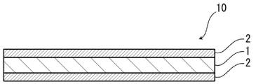
- FIG. 1 is a schematic diagram showing an example of a cross-sectional structure of a gasket member for a polymer electrolyte fuel cell of the present disclosure
- FIG. 1 is a schematic diagram showing an example of a cross-sectional structure of a gasket member for a polymer electrolyte fuel cell of the present disclosure
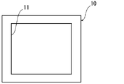
- 1 is an example of a schematic plan view of a gasket member for a polymer electrolyte fuel cell of the present disclosure
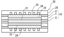
- FIG. 1 is a schematic diagram showing an example of a cross-sectional structure of an electrode-electrolyte membrane laminate with a gasket member of the present disclosure
- FIG. 1 is an example of a schematic plan view of an electrode-electrolyte membrane laminate with a gasket member of the present disclosure.
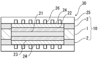
- FIG. 1 is a schematic diagram showing an example of a cross-sectional structure of a polymer electrolyte fuel cell of the present disclosure;
- FIG. 1 is a schematic diagram showing an example of a cross-sectional structure of a polymer electrolyte fuel cell of the present disclosure;
- a polymer electrolyte fuel cell gasket member of the present disclosure comprises a laminate including at least a substrate layer and adhesive layers disposed on both sides of the substrate layer, and the laminate comprises: It is characterized by having a breaking elongation retention rate of 60% or more after standing in water at 120° C. for 300 hours.
- the polymer electrolyte fuel cell gasket member of the present disclosure is excellent in hydrolysis resistance in a high-temperature environment.
- the gasket member for a polymer electrolyte fuel cell of the present disclosure is a gasket member arranged between an electrolyte membrane and a separator of a polymer electrolyte fuel cell, as described later, and is applicable to a wide range of polymer electrolyte fuel cells. can do.
- the gasket member for polymer electrolyte fuel cells of the present disclosure will be described in detail below.
- the numerical range indicated by “-” means “more than” and “less than”.
- the notation of 2 to 15 mm means 2 mm or more and 15 mm or less.
- a gasket member 10 for a polymer electrolyte fuel cell of the present disclosure (hereinafter sometimes referred to as gasket member 10) has, for example, as shown in FIG. It is composed of a laminate including at least a substrate layer 1 and adhesive layers 2 disposed on both sides of the substrate layer 1 . That is, the gasket member 10 is composed of a laminate in which at least the adhesive layer 2, the base material layer 1, and the adhesive layer 2 are laminated in this order.
- the adhesive layers 2 on both sides of the gasket member 10 respectively constitute the outermost layers of the gasket member 10.
- the adhesive layer 2 on one side is arranged on the electrolyte membrane 21 side, and the adhesive layer 2 on the other side is a separator. 25 side (see FIG. 6).
- the gasket member 10 is installed, for example, so as to surround the periphery of the electrode-electrolyte membrane laminate (see the schematic diagrams of the electrode-electrolyte membrane laminate with a gasket member in FIGS. 4 and 5).
- a gasket member 10 thus comprises an opening 11 for inserting the catalyst layers 22, 23 and the gas diffusion layer 24 (see FIG. 3).
- the gasket member 10 may have an anchor coat layer 3 on at least one side of the surface of the base material layer 1, for example, as shown in FIG.
- the adhesiveness between the substrate layer 1 and the adhesive layer 2 can be enhanced by providing the anchor coat layer 3 between the substrate layer 1 and the adhesive layer 2. can be done.
- Anchor coat layers 3 are preferably provided on both sides of the surface of the base material layer 1 . That is, more preferably, the gasket member 10 is composed of a laminate in which at least the adhesive layer 2, the anchor coat layer 3, the base material layer 1, the anchor coat layer 3, and the adhesive layer 2 are laminated in this order.
- the thickness (total thickness) of the laminate constituting the gasket member 10 is adjusted according to the size of the polymer electrolyte fuel cell, and is not particularly limited. , about 50 ⁇ m or less, or, for example, about 30 ⁇ m or more, about 100 ⁇ m or more, about 200 ⁇ m or more, about 250 ⁇ m or more. Preferred ranges for the thickness (total thickness) of the laminate constituting the gasket member 10 are about 30 to 300 ⁇ m, about 30 to 200 ⁇ m, about 30 to 100 ⁇ m, about 30 to 50 ⁇ m, about 100 to 300 ⁇ m, about 100 to 200 ⁇ m, About 200 to 300 ⁇ m and about 250 to 300 ⁇ m can be mentioned.
- the thickness (total thickness) of the laminate constituting the gasket member 10 is , preferably about 400 ⁇ m or less, more preferably about 300 ⁇ m or less, preferably about 30 ⁇ m or more, more preferably about 50 ⁇ m or more, still more preferably about 50 ⁇ m or more, further preferably about 100 ⁇ m or more, and the preferred range is , about 30 to 400 ⁇ m, about 30 to 30 ⁇ m, about 50 to 400 ⁇ m, about 50 to 300 ⁇ m, about 50 ⁇ m to 400 ⁇ m, about 50 ⁇ m to 300 ⁇ m, about 100 to 400 ⁇ m, and about 100 to 300 ⁇ m.
- the thickness of the substrate layer 1 is preferably about 300 ⁇ m or less, more preferably about 200 ⁇ m or less, and is preferably about 20 ⁇ m or more, more preferably about 30 ⁇ m or more, and still more preferably about 50 ⁇ m or more. Preferred ranges include about 20 to 300 ⁇ m, about 20 to 200 ⁇ m, about 30 to 300 ⁇ m, about 30 to 200 ⁇ m, about 50 to 300 ⁇ m, and about 50 to 200 ⁇ m.
- the thickness of the adhesive layer 2 is preferably about 200 ⁇ m or less, more preferably about 100 ⁇ m or less, and is preferably about 10 ⁇ m or more, more preferably about 30 ⁇ m or more, and the preferred range is 10 to 200 ⁇ m. about 10 to 100 ⁇ m, about 30 to 200 ⁇ m, and about 30 to 100 ⁇ m.
- the thickness of the laminate constituting each gasket member 10 is preferably about 200 ⁇ m or less, more preferably about 150 ⁇ m or less, more preferably about 25 ⁇ m or more, more preferably about 50 ⁇ m or more, and a preferable range is about 25 to 200 ⁇ m, 25 to 150 ⁇ m. about 50 to 200 ⁇ m, and about 50 to 150 ⁇ m.
- the thickness of the substrate layer 1 is preferably about 200 ⁇ m or less, more preferably about 150 ⁇ m or less, and is preferably about 10 ⁇ m or more, more preferably about 15 ⁇ m or more. , about 10 to 200 ⁇ m, about 10 to 150 ⁇ m, about 15 to 200 ⁇ m, and about 15 to 150 ⁇ m.
- the thickness of the adhesive layer 2 is preferably about 100 ⁇ m or less, more preferably about 50 ⁇ m or less, and is preferably about 3 ⁇ m or more, more preferably about 15 ⁇ m or more, and a preferable range is 3 to 100 ⁇ m. about 3 to 50 ⁇ m, about 15 to 100 ⁇ m, and about 15 to 50 ⁇ m.
- whether one gasket member 10 or two gasket members 10 are used may be appropriately selected depending on the specifications of the polymer electrolyte fuel cell 30 and the like. Also, the total thickness of the gasket member 10 and the thickness of each layer may be appropriately selected according to the thickness of the polymer electrolyte fuel cell 30 and the like.
- the ratio of the total thickness of the base material layer 1, the adhesive layer 2, and the anchor coat layer 3 provided as necessary to the thickness (total thickness) of the laminate constituting the gasket member 10 is preferably 90. % or more, more preferably 95% or more, still more preferably 98% or more, and even more preferably 100%.
- the ratio of the total thickness of these layers to the thickness (total thickness) of the laminate constituting the gasket member 10 is It is preferably 90% or more, more preferably 95% or more, and still more preferably 98% or more.
- the thickness (total thickness) of the laminate constituting the gasket member 10 is a laminate including the base material layer 1, the adhesive layer 2, and the anchor coat layer 3, the thickness (total thickness) of the laminate constituting the gasket member 10 is The ratio of the total thickness of each layer is, for example, 80% or more, preferably 90% or more, more preferably 95% or more, still more preferably 98% or more, and even more preferably 100%.
- the laminate constituting the gasket member 10 of the present disclosure has a breaking elongation retention rate of 60% or more after standing in water at 120°C for 300 hours. As a result, excellent hydrolysis resistance in a high-temperature environment is exhibited.
- a method for measuring the retention rate of elongation at break of the gasket member 10 is as follows.
- the method of confirming the MD of the gasket member there is a method of observing the cross section of the gasket member (for example, the cross section of the first adhesive layer, the base material, or the second adhesive layer) with an electron microscope to confirm the sea-island structure.
- the direction parallel to the cross section in which the average diameter of the island shape in the direction perpendicular to the thickness direction of the gasket member is maximum can be determined as the MD.
- each cross section A total of 10 cross sections
- the shape of each individual island is observed.
- each island let the straight line distance connecting the leftmost end in the direction perpendicular to the thickness direction of the gasket member and the rightmost end in the perpendicular direction be the diameter y.
- the average of the top 20 diameters y of the island shape is calculated in descending order of diameter y.
- the direction parallel to the cross section in which the average diameter y of the island shape is the largest is determined as the MD.
- the retention rate of elongation at break of the laminate constituting the gasket member 10 is 60% or more, preferably 65% or more, and more preferably 70%. % or more, more preferably 75% or more, more preferably 80% or more, particularly preferably 85% or more.
- a method using a resin having a high glass transition temperature (Tg) can be used.
- Tg glass transition temperature
- the hot shrinkage of the laminate constituting the gasket member 10 when left standing in an environment at a temperature of 150° C. for 30 minutes is preferably 30% or less. , more preferably 20% or less, still more preferably 10% or less.
- the hot shrinkage rate when the laminate constituting the gasket member 10 is left in an environment of 180° C. for 30 minutes is preferably 30% or less, more preferably 20% or less, and still more preferably 20% or less. is 10% or less, more preferably 3% or less, still more preferably 1% or less, still more preferably 0.5% or less.
- a method for measuring the hot shrinkage rate of the gasket member 10 is as follows.
- Hot shrinkage rate ⁇ (XY)/X ⁇ x 100 (I) [X: Dimension before heat treatment in oven, Y: Dimension after heat treatment in oven]
- the base material layer 1 is a layer provided for the purpose of exhibiting a function as a base material of the gasket member 10 .
- a substrate layer 1 is located between two adhesive layers 2 .
- the base material layer 1 is preferably made of a material having excellent hydrolysis resistance, such as polysulfone, polyethersulfone, polyphenylsulfone, polyarylate, polyolefin, polyamide, polyimide, polyetheretherketone, polymethyltene, It preferably contains polyphenylene oxide, polyphenylene sulfide, fluororesin, metal, and the like.
- a material having excellent hydrolysis resistance such as polysulfone, polyethersulfone, polyphenylsulfone, polyarylate, polyolefin, polyamide, polyimide, polyetheretherketone, polymethyltene, It preferably contains polyphenylene oxide, polyphenylene sulfide, fluororesin, metal, and the like.
- polyolefins include polyethylenes such as low-density polyethylene, medium-density polyethylene, high-density polyethylene, and linear low-density polyethylene; ethylene- ⁇ -olefin copolymers; block copolymers of ethylene), random copolymers of polypropylene (for example, random copolymers of propylene and ethylene); propylene- ⁇ -olefin copolymers; ethylene-butene-propylene terpolymers; Among these, polypropylene is preferred.
- the polyolefin resin is a copolymer, it may be a block copolymer or a random copolymer.
- the polyolefin-based resin may be an acid-modified polyolefin.
- the number of polyolefins contained in the base material layer 1 may be one, or two or more.
- Acid-modified polyolefin is a polymer modified by block polymerization or graft polymerization of polyolefin with an acid component.
- the acid-modified polyolefin the above polyolefin, a copolymer obtained by copolymerizing the above polyolefin with a polar molecule such as acrylic acid or methacrylic acid, or a polymer such as crosslinked polyolefin can be used.
- acid components used for acid modification include carboxylic acids such as maleic acid, acrylic acid, itaconic acid, crotonic acid, maleic anhydride and itaconic anhydride, and anhydrides thereof.
- Preferred acid-modified polyolefins include carboxylic acid- or anhydride-modified polyolefins, carboxylic acid- or anhydride-modified polypropylenes, maleic anhydride-modified polyolefins, and maleic anhydride-modified polypropylenes.
- the number of acid-modified polyolefins contained in the base material layer 1 may be one, or two or more.
- polyamides include aliphatic polyamides such as nylon 6, nylon 66, nylon 610, nylon 12, nylon 46, and copolymers of nylon 6 and nylon 66; derived from terephthalic acid and/or isophthalic acid Hexamethylenediamine-isophthalic acid-terephthalic acid copolymer polyamide such as nylon 6I, nylon 6T, nylon 6IT, nylon 6I6T (I represents isophthalic acid, T represents terephthalic acid) containing structural units, polyamide MXD6 (polymeta-xylylene Polyamides containing aromatics such as Pamide); Alicyclic polyamides such as Polyamide PACM6 (polybis(4-aminocyclohexyl)methane adipamide); Furthermore, lactam components and isocyanate components such as 4,4'-diphenylmethane-diisocyanate are copolymerized.
- aliphatic polyamides such as nylon 6, nylon 66, nylon 610, nylon 12, nylon
- polyester amide copolymers and polyether ester amide copolymers which are copolymers of copolymerized polyamides with polyesters or polyalkylene ether glycols; and polyamides such as these copolymers.
- the base layer 1 may contain only one type of polyamide, or two or more types of polyamide.
- polyamide it is particularly preferable to have ⁇ crystals, and specific examples include aliphatic polyamides such as nylon 6, nylon 66, nylon 46, and copolymers of nylon 6 and nylon 66. .
- metals examples include aluminum alloys, copper, zinc, titanium, and stainless steel.
- the base layer 1 preferably contains polysulfone, polyethersulfone, polyphenylsulfone, polyarylate, or polyolefin from the viewpoint of suitably increasing the hydrolysis resistance of the gasket member 10 in a high-temperature environment. More preferably, it comprises ethersulfone, polyphenylsulfone, or polyarylate, even more preferably polyphenylsulfone.
- the substrate layer 1 is preferably made of at least one of these resins, and particularly preferably made of polyphenylsulfone.
- the base material layer 1 is preferably made of a resin having excellent heat resistance.
- the glass transition temperature (Tg) of the resin to be formed is preferably about 160° C. or higher, more preferably about 180° C. or higher, and even more preferably about 200° C. or higher.
- the upper limit of the glass transition temperature (Tg) is, for example, about 450° C. or less.
- the glass transition temperature (Tg) refers to the baseline displacement point of the DSC curve measured by differential scanning calorimeter (DSC).
- the form of the base material layer 1 may be a film or a nonwoven fabric.
- the base material layer 1 when the base material layer 1 is in the form of a film, the base material layer 1 can be suitably formed from the aforementioned resin or metal film.
- the base layer 1 when the base layer 1 is in the form of a non-woven fabric, the base layer 1 can be suitably formed from the non-woven fabric of resin or metal described above.
- the adhesive layer 2 can be impregnated into the gaps of the base material layer 1, which is a nonwoven fabric, so that the physical adhesion between the base material layer 1 and the adhesive layer 2 is enhanced. be able to.
- an anchor coat layer 3 which will be described later, may be provided on the surface of the substrate layer 1. 2 is sufficiently enhanced.
- the anchor coat layer 3 it is preferable to provide the anchor coat layer 3 on the surface of the substrate layer 1 from the viewpoint of enhancing the adhesiveness between the substrate layer 1 and the adhesive layer 2. .
- the base material layer 1 may be a single layer, or may be composed of two or more layers. When the substrate layer 1 is composed of two or more layers, the material and thickness of each layer may be the same or different.
- At least one of the surface and the inside of the base material layer 1 may contain additives such as fillers, flame retardants, antiblocking agents, antioxidants, light stabilizers, tackifiers, and antistatic agents. good.
- additives include metal oxide particles such as alumina, silica, and titania. Only one type of additive may be used, or two or more types may be mixed and used.
- the thickness of the substrate layer 1 is appropriately adjusted depending on the size of the polymer electrolyte fuel cell and the like, but from the viewpoint of suitably increasing the hydrolysis resistance of the gasket member 10 in a high-temperature environment, it is preferably about 20 ⁇ m. More preferably about 40 ⁇ m or more, more preferably about 50 ⁇ m or more, still more preferably 100 ⁇ m or more, and about 200 ⁇ m or less, more preferably about 150 ⁇ m or less, still more preferably about 100 ⁇ m or less.
- Preferred ranges for the thickness of the substrate layer 1 are about 20 to 200 ⁇ m, about 20 to 150 ⁇ m, about 20 to 100 ⁇ m, about 40 to 200 ⁇ m, about 40 to 150 ⁇ m, about 40 to 100 ⁇ m, about 100 to 200 ⁇ m, and 100 to 150 ⁇ m. degree.
- the basis weight of the base material layer 1 is appropriately adjusted depending on the size of the polymer electrolyte fuel cell and the like. From the viewpoint of increasing the 40 g/m 2 or less, more preferably about 30 g/m 2 or less.
- the preferable range of basis weight of the substrate layer 1 is about 5 to 50 g/m 2 , about 5 to 40 g/m 2 , about 5 to 30 g/m 2 , about 10 to 50 g/m 2 .
- the adhesive layers 2 are arranged on both sides of the base material layer 1 .
- the adhesive layers 2 on both sides of the gasket member 10 constitute the outermost layer of the gasket member 10.
- the adhesive layer 2 on one side is arranged on the electrolyte membrane 21 side, and the adhesive layer 2 on the other side is arranged on the separator 25 side. (see FIG. 6).
- the adhesive layer 2 arranged on the side of the electrolyte membrane 21 and the adhesive layer 2 arranged on the side of the separator 25 may be the same in material, thickness, etc., or may be different.
- Additives such as fillers, flame retardants, antiblocking agents, antioxidants, light stabilizers, tackifiers, and antistatic agents may be present on at least one of the surface and interior of the adhesive layer 2.
- Specific examples of additives include metal oxide particles such as alumina, silica, and titania. Only one type of additive may be used, or two or more types may be mixed and used.
- the adhesive layer 2 is preferably made of a resin having excellent adhesiveness with the separator 25 and the electrolyte membrane 21 .
- resins used for forming the adhesive layer 2 include polyolefin resins, adhesives (acrylic resins, aliphatic polyamides, etc.), thermosetting resins (epoxy resins, phenol resins, etc.).
- the resin contained in the adhesive layer 2 may be of only one type, or may be of two or more types.
- the adhesive layer 2 preferably contains at least one of acid-modified polyolefin, imine-modified polyolefin, and carbodiimide-modified polyolefin because it has excellent adhesion to the separator 25 made of metal. It is more preferable to be formed by Furthermore, among acid-modified polyolefins, acid-modified polypropylene is preferable. In the present disclosure, by using the acid-modified polyolefin, together with the base material layer 1, the hydrolysis resistance of the gasket member 10 in a high-temperature environment can be suitably enhanced.
- the adhesive layer 2 may be a single layer, or may be composed of two or more layers. When the adhesive layer 2 is composed of two or more layers, the material and thickness of each layer may be the same or different. Even when the adhesive layer 2 is composed of two or more layers, the outermost layer of the gasket member 10 has excellent adhesiveness to the separator 25 made of metal. It is preferably contained, and more preferably formed of acid-modified polyolefin.
- the thickness of the adhesive layer 2 is appropriately adjusted depending on the size of the polymer electrolyte fuel cell, etc., but from the viewpoint of suitably increasing the hydrolysis resistance of the gasket member 10 in a high-temperature environment, it is preferably about 10 ⁇ m or more, or more. It is preferably about 15 ⁇ m or more, more preferably about 20 ⁇ m or more, and is preferably about 100 ⁇ m or less, more preferably about 80 ⁇ m or less, still more preferably about 60 ⁇ m or less.
- Preferred ranges for the thickness of the adhesive layer 2 are about 10 to 100 ⁇ m, about 10 to 80 ⁇ m, about 10 to 60 ⁇ m, about 15 to 100 ⁇ m, about 15 to 80 ⁇ m, about 15 to 60 ⁇ m, about 20 to 100 ⁇ m, and about 20 to 80 ⁇ m. , and about 20 to 60 ⁇ m.
- the laminate of the base material layer 1 and the adhesive layers 2 on both sides thereof can be manufactured, for example, by extruding a resin that forms the adhesive layers 2 on both sides of the base material layer 1 prepared in advance. and the resin forming the adhesive layer 2 can be extruded at the same time. Alternatively, the substrate layer 1 can be extruded between adhesive layers 2 prepared in advance.
- the method for extruding and laminating the resin is not particularly limited, but known methods such as extrusion lamination, T-die method, inflation method, and thermal lamination method can be applied.
- a resin or the like for forming the anchor coat layer 3 may be applied to at least one side of the surface of the base material layer 1, and an adhesive layer may be laminated thereon.
- the anchor coat layer 3 is a layer provided on at least one side of the surface of the substrate layer 1 as necessary for the purpose of enhancing the adhesiveness between the substrate layer 1 and the adhesive layer 2 .
- the anchor coat layers 3 are preferably provided on both surface sides of the substrate layer 1 .
- the base material layer 1 is preferably made of a resin with excellent heat resistance, but resins with excellent heat resistance generally have low adhesiveness to resins. Therefore, for example, when a highly heat-resistant resin film having a glass transition temperature (Tg) of about 160° C. or higher is used for the substrate layer 1, from the viewpoint of enhancing the adhesiveness between the substrate layer 1 and the adhesive layer 2, Providing the anchor coat layer 3 is effective.
- Tg glass transition temperature
- the material for forming the anchor coat layer 3 is not particularly limited as long as it enhances the adhesion between the base material layer 1 and the adhesive layer 2.
- isocyanate-based, polyethyleneimine-based, polyester-based, polyurethane-based, polyvinyl Resins such as butyral series, acrylic series, aminoethylated acrylic polymer series, styrene/maleic acid copolymer series, rubber series, and epoxy series can be mentioned. These resins can be used singly or in combination of two or more.
- the compound having an isocyanate group is not particularly limited, but from the viewpoint of effectively increasing the adhesiveness between the base material layer 1 and the adhesive layer 2, polyfunctional isocyanate compounds are preferred.
- the polyfunctional isocyanate compound is not particularly limited as long as it is a compound having two or more isocyanate groups.
- polyfunctional isocyanate curing agents include pentane diisocyanate (PDI), isophorone diisocyanate (IPDI), hexamethylene diisocyanate (HDI), tolylene diisocyanate (TDI), diphenylmethane diisocyanate (MDI), m-xylylene diisocyanate ( XDI), polymers or nurates thereof, mixtures thereof, copolymers with other polymers, and the like.
- PDI pentane diisocyanate
- IPDI isophorone diisocyanate
- HDI hexamethylene diisocyanate
- TDI tolylene diisocyanate
- MDI diphenylmethane diisocyanate
- XDI m-xylylene diisocyanate
- polymers or nurates thereof mixtures thereof, copolymers with other polymers, and the like.
- adducts, burettes, isocyanurates and the like
- Triisocyanates such as triphenylmethane-4,4′,4′′-triisocyanate and tris(p-isocyanatophenyl)thiophosphate are also included.
- the compound having an isocyanate group used for forming the anchor coat layer 3 is , may be one type, or two or more types may be used.
- polyurethane systems include a two-component mixture of polyester resin and polyfunctional isocyanate compound, and a two-component mixture of polycarbonate diol and polyfunctional isocyanate compound.
- Specific examples of polyurethane systems include a two-part mixture of polyester resin and hexamethylene diisocyanate, a two-part mixture of polycarbonate diol and polymethylene polyphenyl polyisocyanate, and the like.
- the thickness of the anchor coat layer 3 is appropriately adjusted depending on the size of the polymer electrolyte fuel cell, etc., but from the viewpoint of suitably increasing the hydrolysis resistance of the gasket member 10 in a high-temperature environment, it is preferably about 0.02 g. /m 2 or more, more preferably 0.05 g/m 2 or more, more preferably about 0.1 g/m 2 or more, still more preferably about 0.3 g/m 2 or more, still more preferably about 0.5 g/m 2 and preferably about 5 g/m 2 or less, more preferably about 4 g/m 2 or less, even more preferably about 3 g/m 2 or less.
- Preferred ranges for the thickness of the anchor coat layer 3 are approximately 0.02 to 5 g/m 2 , approximately 0.02 to 4 g/m 2 , approximately 0.02 to 3 g/m 2 , and approximately 0.05 to 5 g/m 2 .
- the gasket member-equipped electrode-electrolyte membrane laminate 20 of the present disclosure is obtained by attaching the gasket member 10 of the present disclosure to the electrode-electrolyte membrane laminate (see FIG. 4).
- the electrode-electrolyte membrane laminate 20 with a gasket member of the present disclosure includes an electrode-electrolyte membrane laminate in which the catalyst layers 22 and 23 and the gas diffusion layer 24 are arranged on both sides of the electrolyte membrane 21; A frame-shaped gasket member 10 is arranged so as to cover the outer peripheral edge of the electrolyte membrane laminate, and the gasket member 10 is arranged at least on both sides of the base layer 1 and the base layer 1.
- the laminate is characterized by having a breaking elongation retention rate of 60% or more after standing in water at 120° C. for 300 hours.
- the gasket member 10 of the present disclosure can also be used as a pair of members that are arranged so as to cover the outer peripheral edge of the electrode-electrolyte membrane laminate from one side and the other side and are attached to each other.
- one gasket member 10 may cover the outer periphery of the electrode-electrolyte membrane laminate.
- the electrolyte membrane 21 is not particularly limited, and may be, for example, those used in known polymer electrolyte fuel cells.
- the electrolyte membrane 21 is formed, for example, by coating a substrate with a solution containing a hydrogen ion conductive polymer electrolyte and drying it.
- a hydrogen ion conductive polymer electrolyte for example, a perfluorosulfonic acid-based fluorine ion exchange resin, more specifically, a perfluorocarbon sulfonic acid system in which the CH bonds of a hydrocarbon-based ion exchange membrane are substituted with fluorine Examples include polymers (PFS-based polymers).
- the concentration of the hydrogen ion conductive polymer electrolyte contained in the solution containing the hydrogen ion conductive polymer electrolyte is usually about 5-60% by weight, preferably about 20-40% by weight.
- the thickness of the electrolyte membrane 21 is usually about 3-50 ⁇ m, preferably about 5-20 ⁇ m.
- the end faces of the electrolyte membrane 21 do not need to be aligned with the end faces of the catalyst layers 22 and 23.
- the adhesive layer 2 of the gasket member 10 may cover the projecting portion of the electrolyte membrane 21 .
- one of the catalyst layers 22 and 23 is an anode catalyst layer, and the other is a cathode catalyst layer.
- the catalyst layers 22 and 23 are not particularly limited, and may be those used in known polymer electrolyte fuel cells, for example.
- the catalyst layers 22 and 23 are, for example, platinum-containing catalyst layers.
- the catalyst layers 22 and 23 contain, for example, carbon particles supporting catalyst particles and a hydrogen ion conductive polymer electrolyte. Examples of catalyst particles include platinum and platinum compounds. Examples of platinum compounds include alloys of platinum with at least one metal selected from the group consisting of ruthenium, palladium, nickel, molybdenum, iridium, iron, and the like.
- the catalyst particles contained in the cathode catalyst layer are platinum, and the catalyst particles contained in the anode catalyst layer are an alloy of the metal and platinum.
- the hydrogen ion conductive polymer electrolyte the same material as that used for the electrolyte membrane 21 can be used.
- the size and shape of the electrolyte membrane 21 and the catalyst layers 22 and 23 are adjusted according to the size of the polymer electrolyte fuel cell, and the size and shape of the gasket member 10 of the present disclosure are also adjusted so as to function as a gasket member. (that is, having mechanical strength to withstand hot pressing and exhibiting gas barrier properties to the extent that fuel and oxidant do not leak to the outside) are adjusted as appropriate according to these sizes.
- the polymer electrolyte fuel cell 30 of the present disclosure is a polymer electrolyte fuel cell utilizing the gasket member 10 of the present disclosure. That is, the polymer electrolyte fuel cell 30 of the present disclosure includes the electrode-electrolyte membrane laminate 20 with a gasket member of the present disclosure.
- the polymer electrolyte fuel cell 30 includes a catalyst layer-electrolyte membrane laminate, and a gas diffusion layer 24 is formed on each of the catalyst layers 22 and 23 of the catalyst layer-electrolyte membrane laminate.
- An electrode-electrolyte membrane laminate is constructed.
- the catalyst layers 22 and 23 and the gas diffusion layer 24 constitute electrodes (anode and cathode), respectively.
- a gasket member 10 of the present disclosure is placed on the outer peripheral edge of the electrolyte membrane 21 so as to surround these electrodes.
- a separator 25 having a gas flow path 26 formed thereon is provided so as to sandwich the electrode-electrolyte membrane laminate on which the gasket member 10 is provided from above and below.
- the gas diffusion layer 24 is not particularly limited, and may be, for example, those used in known polymer electrolyte fuel cells. That is, the gas diffusion layer 24 can use various gas diffusion layers that constitute the anode and the cathode. It consists of a conductive substrate. Examples of porous conductive substrates include carbon paper and carbon cloth.
- the separator 25 is not particularly limited, and may be, for example, one used in known polymer electrolyte fuel cells.
- the separator 25 may be any conductive plate that is stable even in the environment inside the fuel cell, and generally, a metal plate of titanium, aluminum, copper, stainless steel, or the like in which the gas flow paths 26 are formed is used.
- the operating temperature of the polymer electrolyte fuel cell 30 of the present disclosure is not particularly limited. may be used in By increasing the operating temperature of the fuel cell, the power density can be increased.
- the upper limit of the operating temperature of the polymer electrolyte fuel cell 30 of the present disclosure is, for example, 150° C. or less.
- Example 1 ⁇ Manufacture of Gasket Member for Polymer Electrolyte Fuel Cell> (Example 1) A polysulfone (PSU) film (thickness: 100 ⁇ m, Tg: 180° C.) was prepared as a base layer. Next, a resin composition containing a compound having an isocyanate group (polyester resin and hexamethylene diisocyanate two-liquid mixture) is applied to both surfaces of the substrate layer to form an anchor coat layer (thickness: 0.5 g/m 2 ). formed.
- PSU polysulfone
- maleic anhydride-modified polypropylene (PPa) was melt-extruded to a thickness of 50 ⁇ m to form an adhesive layer, and an adhesive layer (thickness: 50 ⁇ m) was formed.
- /anchor coat layer (thickness 0.5 g/m 2 )/base layer (thickness 100 ⁇ m)/anchor coat layer (thickness 0.5 g/m 2 )/adhesive layer (thickness 50 ⁇ m) were laminated in this order.
- a gasket member for a polymer electrolyte fuel cell was obtained.
- Example 2 An adhesive layer (50 ⁇ m thick )/anchor coat layer (thickness 0.5 g/m 2 )/base layer (thickness 100 ⁇ m)/anchor coat layer (thickness 0.5 g/m 2 )/adhesive layer (thickness 50 ⁇ m) are laminated in this order. Thus, a polymer electrolyte fuel cell gasket member (thickness: 200 ⁇ m) was obtained.
- Example 3 An adhesive layer (50 ⁇ m thick )/anchor coat layer (thickness 0.5 g/m 2 )/base layer (thickness 100 ⁇ m)/anchor coat layer (thickness 0.5 g/m 2 )/adhesive layer (thickness 50 ⁇ m) are laminated in this order. Thus, a polymer electrolyte fuel cell gasket member (thickness: 200 ⁇ m) was obtained.
- Example 4 As the resin composition (anchor coat material) that forms the anchor coat layer, instead of the "resin composition containing a compound having an isocyanate group (polyester resin and hexamethylene diisocyanate two-component mixture)", "two-component urethane (polycarbonate diol and polymethylene polyphenyl polyisocyanate)” was used in the same manner as in Example 3 to form an adhesive layer (thickness: 50 ⁇ m)/anchor coat layer (thickness: 0.5 g/m 2 )/base A polymer electrolyte fuel cell gasket member (thickness: 200 ⁇ m) in which material layer (thickness: 100 ⁇ m)/anchor coat layer (thickness: 0.5 g/m 2 )/adhesive layer (thickness: 50 ⁇ m) were laminated in this order was obtained. .
- Example 5 As the resin composition (anchor coat material) forming the anchor coat layer, "triphenylmethane-4,4 Adhesive layer (thickness: 50 ⁇ m)/anchor coat layer (thickness: 0.5 g/m 2 ) in the same manner as in Example 3, except that ',4''-triisocyanate (one-liquid curing type) was used.
- a polymer electrolyte fuel cell gasket member (thickness 200 ⁇ m) in which /base layer (thickness 100 ⁇ m) /anchor coat layer (thickness 0.5 g/m 2 ) /adhesive layer (thickness 50 ⁇ m) are laminated in order. Obtained.
- Example 7 As the resin composition (anchor coat material) that forms the anchor coat layer, instead of the "resin composition containing a compound having an isocyanate group (polyester resin and hexamethylene diisocyanate two-liquid mixture)", "polyisocyanate of hexamethylene diisocyanate ( Adhesive layer (thickness: 50 ⁇ m)/anchor coat layer (thickness: 0.5 g/m 2 )/base material layer (thickness: 100 ⁇ m) )/anchor coat layer (thickness 0.5 g/m 2 )/adhesive layer (thickness 50 ⁇ m) laminated in this order to obtain a polymer electrolyte fuel cell gasket member (thickness 200 ⁇ m).
- PEN polyethylene naphthalate
- the measurement sample attachel strength to a tensile tester, measure the adhesive strength (peel strength) between the metal layer and the adhesive layer under the conditions of a tensile speed of 300 mm / min and a distance between the gauge lines of 50 mm, and seal the maximum strength at the time of peeling.
- the strength was set to (N/15 mm).
- the average value of 3 measurements was taken.
- the hot press conditions were a fixed temperature of 170° C., a surface pressure of 1 MPa, and a pressing time of 20 seconds (s), while changing the temperature.
- the peeling direction was 180°, and the size of the adhesive portion of the stainless steel plate (SUS304) in the measurement sample was 15 mm wide and 30 mm long.
- Hot shrinkage rate was measured by heating a test piece of a gasket member cut into a size of 10 cm in length (MD) x 10 cm in width (TD) in an oven at 180°C for 30 minutes.
- the dimensional change rates before and after heating in the two directions) were obtained based on the following formula (I), and the absolute values of the dimensional change rates in the two directions were calculated as the average value.
- Hot shrinkage rate (%) ⁇ (XY)/X ⁇ x 100 (I) [X: Dimension before heat treatment in oven, Y: Dimension after heat treatment in oven]
- the gasket members of Examples 1 to 7 are composed of a laminate having a base material layer and adhesive layers arranged on both sides of the base material layer, and after standing in water at 120° C. for 300 hours, The retention rate of elongation at break was 60% or more, and the hydrolysis resistance in a high temperature environment was excellent. Moreover, the gasket members of Examples 1 to 7 had good adhesiveness to the separator.
- Section 1 At least, it is composed of a laminate including a base material layer and adhesive layers arranged on both sides of the base material layer, A gasket member for a polymer electrolyte fuel cell, wherein the laminate has a breaking elongation retention rate of 60% or more after standing in water at 120° C. for 300 hours.
- Section 2. The base material layer is selected from the group consisting of polysulfone, polyethersulfone, polyphenylsulfone, polyarylate, polyolefin, polyamide, polyimide, polyetheretherketone, polymethyltempene, polyphenylene oxide, polyphenylene sulfide, fluororesin, and metal.
- the base material layer is selected from the group consisting of polysulfone, polyethersulfone, polyphenylsulfone, polyarylate, polyolefin, polyamide, polyimide, polyetheretherketone, polymethyltempene, polyphenylene oxide, polyphenylene sulfide, fluorores
- the gasket member for a polymer electrolyte fuel cell according to Item 1 comprising at least one of Item 3.
- Item 3. The gasket member for a polymer electrolyte fuel cell according to Item 1 or 2, wherein the base material layer is a nonwoven fabric.
- Section 4. Item 4.
- Item 6. Item 6.
- the gasket member for a polymer electrolyte fuel cell according to any one of Items 1 to 5, wherein the adhesive layer has a thickness of 10 ⁇ m or more and 100 ⁇ m or less.
- Item 7. an electrode-electrolyte membrane laminate in which a catalyst layer and a gas diffusion layer are arranged on both sides of the electrolyte membrane; a frame-shaped gasket member disposed so as to cover the outer peripheral edge of the electrode-electrolyte membrane laminate; with The gasket member is composed of a laminate including at least a base material layer and adhesive layers disposed on both sides of the base material layer, An electrode-electrolyte membrane laminate with a gasket member, wherein the laminate has a breaking elongation retention rate of 60% or more after standing in water at 120° C.
- the base material layer is selected from the group consisting of polysulfone, polyethersulfone, polyphenylsulfone, polyarylate, polyolefin, polyamide, polyimide, polyetheretherketone, polymethyltempene, polyphenylene oxide, polyphenylene sulfide, fluororesin, and metal.
- Item 11. Item 11. The electrode-electrolyte membrane laminate with a gasket member according to any one of Items 7 to 10, wherein the base material layer has a thickness of 20 ⁇ m or more and 200 ⁇ m or less.
- Item 12. Item 12. The electrode-electrolyte membrane laminate with a gasket member according to any one of Items 7 to 11, wherein the adhesive layer has a thickness of 10 ⁇ m or more and 100 ⁇ m or less.
- a polymer electrolyte fuel cell comprising the electrode-electrolyte membrane laminate with a gasket member according to any one of Items 7 to 12.
- Item 14 A method for producing a polymer electrolyte fuel cell gasket member composed of a laminate comprising at least a base material layer and adhesive layers disposed on both sides of the base material layer, the method comprising: A step of laminating the adhesive layer on both sides of the base material layer, The method for producing a polymer electrolyte fuel cell gasket member, wherein the laminate has a breaking elongation retention rate of 60% or more after standing in water at 120° C. for 300 hours.
- Base material layer 2 Adhesive layer 3
- Anchor coat layer 10 Gasket member 11 Opening 20
- Electrolyte membrane laminate with gasket member 21 Electrolyte membranes 22, 23 Catalyst layer 24 Gas diffusion layer 25 Separator 26 Gas channel 30 Solid polymer type Fuel cell
Abstract
Description
基材層と、前記基材層の両面側に配置された接着層とを備える積層体から構成されており、
前記積層体は、120℃の水中に300時間静置された後における破断伸度保持率が、60%以上である、固体高分子形燃料電池用ガスケット部材。
本開示の固体高分子形燃料電池用ガスケット部材10(以下、ガスケット部材10と表記することがある)は、例えば図1に示すように、少なくとも、基材層1と、基材層1の両面側に配置された接着層2とを備える積層体から構成されている。すなわち、ガスケット部材10は、少なくとも、接着層2、基材層1、接着層2がこの順に積層された積層体から構成されている。ガスケット部材10の両側の接着層2は、それぞれ、ガスケット部材10の最外層を構成しており、一方側の接着層2は、電解質膜21側に配置され、他方側の接着層2は、セパレータ25側に配置される(図6を参照)。
破断伸度保持率は以下の方法で実施する。具体的には、120℃の水に浸漬し300時間静置した後、サンプルの破断伸度を測定し、得られた測定値を前記耐久試験前の破断伸度(初期破断伸度)で除算し、破断伸度保持率を求めた。破断伸度は、フィルムを幅(TD)15mm、長さ(MD)50mmの短冊状に裁断し、引張試験機を用いて、引張速度200mm/分、標線間距離を20mmの条件で引っ張ることにより破断するまでの伸度を測定した。試験環境は23℃とし、3回測定した平均値とする。
破壊伸度保持率(%)=耐久試験後の破断伸度÷耐久試験前の破断伸度(初期破断伸度)×100
熱間収縮率は、ガスケット部材を縦(MD)10cm×横(TD)10cmのサイズに切断した試験片を、150℃又は180℃のオーブン内で30分間加熱し、試験片の縦方向及び横方向(直交する2方向)における加熱前後の寸法変化率を下記式(I)に基づいて求め、2方向の寸法変化率の絶対値を平均値として算出したものである。
熱間収縮率(%)={(X-Y)/X}×100 ・・・(I)
[X:オーブン内での加熱処理前の寸法、Y:オーブン内での加熱処理後の寸法]
[基材層1]
本開示において、基材層1は、ガスケット部材10の基材としての機能を発揮させることなどを目的として設けられる層である。基材層1は、2つの接着層2の間に位置する。
ガスケット部材10において、接着層2は、基材層1の両側に配置されている。ガスケット部材10の両側の接着層2は、ガスケット部材10の最外層を構成しており、一方側の接着層2は、電解質膜21側に配置され、他方側の接着層2は、セパレータ25側に配置される(図6を参照)。なお、電解質膜21側に配置される接着層2と、セパレータ25側に配置される接着層2とは、素材、厚みなどが同一であってもよいし、異なってもよい。また、接着層2の表面及び内部の少なくとも一方には、フィラー、難燃剤、アンチブロッキング剤、酸化防止剤、光安定剤、粘着付与剤、耐電防止剤等の添加剤が存在していてもよい。添加剤の具体例としては、例えば、アルミナ、シリカ、チタニアなどの金属酸化物粒子が挙げられる。添加剤は、1種類のみを用いてもよいし、2種類以上を混合して用いてもよい。
アンカーコート層3は、基材層1と接着層2との接着性を高めることを目的として、必要に応じて、基材層1の表面の少なくとも一方側に設けられる層である。アンカーコート層3は、基材層1の両面側に設けられていることが好ましい。
本開示のガスケット部材付き電極-電解質膜積層体20は、電極-電解質膜積層体に本開示のガスケット部材10が取り付けられたものである(図4参照)。本開示のガスケット部材付き電極-電解質膜積層体20は、具体的には、電解質膜21の両面に触媒層22,23及びガス拡散層24が配置された電極-電解質膜積層体と、電極-電解質膜積層体の外周縁部を覆うように配置された、枠状のガスケット部材10とを備え、ガスケット部材10は、少なくとも、基材層1と、基材層1の両面側に配置された接着層2とを備える積層体から構成されており、当該積層体は、120℃の水中に300時間静置された後における破断伸度保持率が、60%以上であることを特徴としている。
本開示の固体高分子形燃料電池30は、本開示のガスケット部材10を利用した固体高分子形燃料電池である。すなわち、本開示の固体高分子形燃料電池30は、本開示のガスケット部材付き電極-電解質膜積層体20を備える。
(実施例1)
基材層として、ポリスルホン(PSU)フィルム(厚さ100μm、Tg180℃)を用意した。次に、基材層の両面に、イソシアネート基を有する化合物を含む樹脂組成物(ポリエステル樹脂およびヘキサメチレンジイソシアネート2液混合物)を塗布して、アンカーコート層(厚さ0.5g/m2)を形成した。さらに、両側のアンカーコート層の表面に、それぞれ、無水マレイン酸変性ポリプロピレン(PPa)を厚さ50μmとなるようにして溶融押出しすることにより、接着層を形成して、接着層(厚さ50μm)/アンカーコート層(厚さ0.5g/m2)/基材層(厚さ100μm)/アンカーコート層(厚さ0.5g/m2)/接着層(厚さ50μm)が順に積層された固体高分子形燃料電池用ガスケット部材(厚み200μm)を得た。
基材層として、ポリスルホン(PSU)フィルムの代わりに、ポリエーテルスルホン(PESU)フィルム(厚さ100μm、Tg220℃)を用いたこと以外は、実施例1と同様にして、接着層(厚さ50μm)/アンカーコート層(厚さ0.5g/m2)/基材層(厚さ100μm)/アンカーコート層(厚さ0.5g/m2)/接着層(厚さ50μm)が順に積層された固体高分子形燃料電池用ガスケット部材(厚み200μm)を得た。
基材層として、ポリスルホン(PSU)フィルムの代わりに、ポリフェニルスルホン(PPSU)フィルム(厚さ100μm、Tg220℃)を用いたこと以外は、実施例1と同様にして、接着層(厚さ50μm)/アンカーコート層(厚さ0.5g/m2)/基材層(厚さ100μm)/アンカーコート層(厚さ0.5g/m2)/接着層(厚さ50μm)が順に積層された固体高分子形燃料電池用ガスケット部材(厚み200μm)を得た。
アンカーコート層を形成する樹脂組成物(アンカーコート材料)として、「イソシアネート基を有する化合物を含む樹脂組成物(ポリエステル樹脂およびヘキサメチレンジイソシアネート2液混合物)」の代わりに「2液型ウレタン(ポリカーボネートジオールとポリメチレンポリフェニルポリイソシアネート2液混合物)」を用いたこと以外は、実施例3と同様にして、接着層(厚さ50μm)/アンカーコート層(厚さ0.5g/m2)/基材層(厚さ100μm)/アンカーコート層(厚さ0.5g/m2)/接着層(厚さ50μm)が順に積層された固体高分子形燃料電池用ガスケット部材(厚み200μm)を得た。
アンカーコート層を形成する樹脂組成物(アンカーコート材料)として、「イソシアネート基を有する化合物を含む樹脂組成物(ポリエステル樹脂およびヘキサメチレンジイソシアネート2液混合物)」の代わりに「トリフェニルメタン-4,4’,4”-トリイソシアネート(1液硬化タイプ)」を用いたこと以外は、実施例3と同様にして、接着層(厚さ50μm)/アンカーコート層(厚さ0.5g/m2)/基材層(厚さ100μm)/アンカーコート層(厚さ0.5g/m2)/接着層(厚さ50μm)が順に積層された固体高分子形燃料電池用ガスケット部材(厚み200μm)を得た。
アンカーコート層を形成する樹脂組成物(アンカーコート材料)として、「イソシアネート基を有する化合物を含む樹脂組成物(ポリエステル樹脂およびヘキサメチレンジイソシアネート2液混合物)」の代わりに「ポリメチレンポリフェニルポリイソシアネート(1液硬化タイプ)」を用いたこと以外は、実施例3と同様にして、接着層(厚さ50μm)/アンカーコート層(厚さ0.5g/m2)/基材層(厚さ100μm)/アンカーコート層(厚さ0.5g/m2)/接着層(厚さ50μm)が順に積層された固体高分子形燃料電池用ガスケット部材(厚み200μm)を得た。
アンカーコート層を形成する樹脂組成物(アンカーコート材料)として、「イソシアネート基を有する化合物を含む樹脂組成物(ポリエステル樹脂およびヘキサメチレンジイソシアネート2液混合物)」の代わりに「ヘキサメチレンジイソシアネートのポリイソシアネート(1液硬化タイプ)」を用いたこと以外は、実施例3と同様にして、接着層(厚さ50μm)/アンカーコート層(厚さ0.5g/m2)/基材層(厚さ100μm)/アンカーコート層(厚さ0.5g/m2)/接着層(厚さ50μm)が順に積層された固体高分子形燃料電池用ガスケット部材(厚み200μm)を得た。
基材層として、ポリスルホン(PSU)フィルムの代わりに、固体高分子形燃料電池用ガスケット部材の基材層に一般的に用いられているポリエチレンナフタレート(PEN)フィルム(厚さ100μm、Tg155℃)を用いたこと以外は、実施例1と同様にして、接着層(厚さ50μm)/アンカーコート層(厚さ0.5g/m2)/基材層(厚さ100μm)/アンカーコート層(厚さ0.5g/m2)/接着層(厚さ50μm)が順に積層された固体高分子形燃料電池用ガスケット部材(厚み200μm)を得た。
実施例及び比較例で製造した固体高分子形燃料電池用ガスケット部材について、それぞれ、以下の測定条件によって、120℃の水中(耐熱・耐圧容器内)に300時間静置された後における破断伸度保持率(%)を測定した。結果を表1に示す。120℃の水に浸漬し300時間静置した後、サンプルの破断伸度を測定し、得られた測定値を前記耐久試験前の破断伸度(初期破断伸度)で除算し、破断伸度保持率を求める。破断伸度は、フィルムを幅(TD)15mm、長さ(MD)50mmの短冊状に裁断し、引張試験機を用いて、引張速度200mm/分、標線間距離を20mmの条件で引っ張ることにより破断するまでの伸度を測定した。試験環境は23℃とし、3回測定した平均値とする。
破壊伸度保持率(%)=耐久試験後の破断伸度÷耐久試験前の破断伸度(初期破断伸度)×100
実施例及び比較例で製造した固体高分子形燃料電池用ガスケット部材について、それぞれ、以下の測定条件によって、セパレータに見立てたステンレス鋼板(SUS304)に対する接着強度(N)を測定した。結果を表1に示す。JIS K7127:1999の規定に準拠して、25℃環境の剥離強度を次のようにして測定した。サンプルからTD方向15mm幅の短冊状にサンプルを切り出し、金属-接着層を熱プレスにより接着し測定用サンプルを作成した。次に、測定用サンプルを引張試験機に取り付け、引張速度300mm/min、標線間距離50mmの条件で金属層-接着層間の接着強度(剥離強度)を測定し、剥離時の最大強度をシール強度(N/15mm)とした。3回測定した平均値とした。熱プレス条件は、温度170℃、面圧を1MPa、プレス時間を20秒(s)に固定し、温度を変更して測定した。剥離方向は180°方向とし、測定用サンプルにおけるステンレス鋼板(SUS304)の接着部の大きさは幅15mm、長さ30mmである。
熱間収縮率は、ガスケット部材を縦(MD)10cm×横(TD)10cmのサイズに切断した試験片を、180℃のオーブン内で30分間加熱し、試験片の縦方向及び横方向(直交する2方向)における加熱前後の寸法変化率を下記式(I)に基づいて求め、2方向の寸法変化率の絶対値を平均値として算出した。
熱間収縮率(%)={(X-Y)/X}×100 ・・・(I)
[X:オーブン内での加熱処理前の寸法、Y:オーブン内での加熱処理後の寸法]

項1. 少なくとも、基材層と、前記基材層の両面側に配置された接着層とを備える積層体から構成されており、
前記積層体は、120℃の水中に300時間静置された後における破断伸度保持率が、60%以上である、固体高分子形燃料電池用ガスケット部材。
項2. 前記基材層は、ポリスルホン、ポリエーテルスルホン、ポリフェニルスルホン、ポリアリレート、ポリオレフィン、ポリアミド、ポリイミド、ポリエーテルエーテルケトン、ポリメチルテンペン、ポリフェニレンオキサイド、ポリフェニレンサルファイド、フッ素樹脂、及び金属からなる群より選択される少なくとも1種を含む、項1に記載の固体高分子形燃料電池用ガスケット部材。
項3. 前記基材層が、不織布である、項1または2に記載の固体高分子形燃料電池用ガスケット部材。
項4. 前記基材層の表面の少なくとも一方側にアンカーコート層を備える、項1~3のいずれか1項に記載の固体高分子形燃料電池用ガスケット部材。
項5. 前記基材層の厚みが、20μm以上200μm以下である、項1~4のいずれか1項に記載の固体高分子形燃料電池用ガスケット部材。
項6. 前記接着層の厚みが、10μm以上100μm以下である、項1~5のいずれか1項に記載の固体高分子形燃料電池用ガスケット部材。
項7. 電解質膜の両面に触媒層及びガス拡散層が配置された電極-電解質膜積層体と、
前記電極-電解質膜積層体の外周縁部を覆うように配置された、枠状のガスケット部材と、
を備え、
前記ガスケット部材は、少なくとも、基材層と、前記基材層の両面側に配置された接着層とを備える積層体から構成されており、
前記積層体は、120℃の水中に300時間静置された後における破断伸度保持率が、60%以上である、ガスケット部材付き電極-電解質膜積層体。
項8. 前記基材層は、ポリスルホン、ポリエーテルスルホン、ポリフェニルスルホン、ポリアリレート、ポリオレフィン、ポリアミド、ポリイミド、ポリエーテルエーテルケトン、ポリメチルテンペン、ポリフェニレンオキサイド、ポリフェニレンサルファイド、フッ素樹脂、及び金属からなる群より選択される少なくとも1種を含む、項7に記載のガスケット部材付き電極-電解質膜積層体。
項9. 前記基材層が、不織布である、項7または8に記載のガスケット部材付き電極-電解質膜積層体。
項10. 前記基材層の表面の少なくとも一方側にアンカーコート層を備える、項7~9のいずれか1項に記載のガスケット部材付き電極-電解質膜積層体。
項11. 前記基材層の厚みが、20μm以上200μm以下である、項7~10のいずれか1項に記載のガスケット部材付き電極-電解質膜積層体。
項12. 前記接着層の厚みが、10μm以上100μm以下である、項7~11のいずれか1項に記載のガスケット部材付き電極-電解質膜積層体。
項13. 項7~12のいずれか1項に記載のガスケット部材付き電極-電解質膜積層体を備える、固体高分子形燃料電池。
項14. 少なくとも、基材層と、前記基材層の両面側に配置された接着層とを備える積層体から構成された固体高分子形燃料電池用ガスケット部材の製造方法であって、
前記基材層の両面側に、前記接着層を積層する工程を備えており、
前記積層体は、120℃の水中に300時間静置された後における破断伸度保持率が、60%以上である、固体高分子形燃料電池用ガスケット部材の製造方法。
2 接着層
3 アンカーコート層
10 ガスケット部材
11 開口部
20 ガスケット部材付き電極-電解質膜積層体
21 電解質膜
22,23 触媒層
24 ガス拡散層
25 セパレータ
26 ガス流路
30 固体高分子形燃料電池
Claims (14)
- 少なくとも、基材層と、前記基材層の両面側に配置された接着層とを備える積層体から構成されており、
前記積層体は、120℃の水中に300時間静置された後における破断伸度保持率が、60%以上である、固体高分子形燃料電池用ガスケット部材。 - 前記基材層は、ポリスルホン、ポリエーテルスルホン、ポリフェニルスルホン、ポリアリレート、ポリオレフィン、ポリアミド、ポリイミド、ポリエーテルエーテルケトン、ポリメチルテンペン、ポリフェニレンオキサイド、ポリフェニレンサルファイド、フッ素樹脂、及び金属からなる群より選択される少なくとも1種を含む、請求項1に記載の固体高分子形燃料電池用ガスケット部材。
- 前記基材層が、不織布である、請求項1または2に記載の固体高分子形燃料電池用ガスケット部材。
- 前記基材層の表面の少なくとも一方側にアンカーコート層を備える、請求項1~3のいずれか1項に記載の固体高分子形燃料電池用ガスケット部材。
- 前記基材層の厚みが、20μm以上200μm以下である、請求項1~4のいずれか1項に記載の固体高分子形燃料電池用ガスケット部材。
- 前記接着層の厚みが、10μm以上100μm以下である、請求項1~5のいずれか1項に記載の固体高分子形燃料電池用ガスケット部材。
- 電解質膜の両面に触媒層及びガス拡散層が配置された電極-電解質膜積層体と、
前記電極-電解質膜積層体の外周縁部を覆うように配置された、枠状のガスケット部材と、
を備え、
前記ガスケット部材は、少なくとも、基材層と、前記基材層の両面側に配置された接着層とを備える積層体から構成されており、
前記積層体は、120℃の水中に300時間静置された後における破断伸度保持率が、60%以上である、ガスケット部材付き電極-電解質膜積層体。 - 前記基材層は、ポリスルホン、ポリエーテルスルホン、ポリフェニルスルホン、ポリアリレート、ポリオレフィン、ポリアミド、ポリイミド、ポリエーテルエーテルケトン、ポリメチルテンペン、ポリフェニレンオキサイド、ポリフェニレンサルファイド、フッ素樹脂、及び金属からなる群より選択される少なくとも1種を含む、請求項7に記載のガスケット部材付き電極-電解質膜積層体。
- 前記基材層が、不織布である、請求項7または8に記載のガスケット部材付き電極-電解質膜積層体。
- 前記基材層の表面の少なくとも一方側にアンカーコート層を備える、請求項7~9のいずれか1項に記載のガスケット部材付き電極-電解質膜積層体。
- 前記基材層の厚みが、20μm以上200μm以下である、請求項7~10のいずれか1項に記載のガスケット部材付き電極-電解質膜積層体。
- 前記接着層の厚みが、10μm以上100μm以下である、請求項7~11のいずれか1項に記載のガスケット部材付き電極-電解質膜積層体。
- 請求項7~12のいずれか1項に記載のガスケット部材付き電極-電解質膜積層体を備える、固体高分子形燃料電池。
- 少なくとも、基材層と、前記基材層の両面側に配置された接着層とを備える積層体から構成された固体高分子形燃料電池用ガスケット部材の製造方法であって、
前記基材層の両面側に、前記接着層を積層する工程を備えており、
前記積層体は、120℃の水中に300時間静置された後における破断伸度保持率が、60%以上である、固体高分子形燃料電池用ガスケット部材の製造方法。
Priority Applications (5)
| Application Number | Priority Date | Filing Date | Title |
|---|---|---|---|
| JP2022548019A JP7173419B1 (ja) | 2021-02-10 | 2022-02-10 | 固体高分子形燃料電池用ガスケット部材、ガスケット部材付き電極-電解質膜積層体、及び固体高分子形燃料電池 |
| EP22752805.6A EP4293764A1 (en) | 2021-02-10 | 2022-02-10 | Gasket member for solid polymer fuel cell, electrode-electrolyte membrane laminate with gasket member, and solid polymer fuel cell |
| CN202280014386.4A CN116868384A (zh) | 2021-02-10 | 2022-02-10 | 固体高分子型燃料电池用衬垫部件、带衬垫部件的电极-电解质膜叠层体和固体高分子型燃料电池 |
| US18/276,804 US20240128481A1 (en) | 2021-02-10 | 2022-02-10 | Gasket member for solid polymer fuel cell, electrode-electrolyte membrane laminate with gasket member, and solid polymer fuel cell |
| JP2022176376A JP2023011835A (ja) | 2021-02-10 | 2022-11-02 | 固体高分子形燃料電池用ガスケット部材、ガスケット部材付き電極-電解質膜積層体、及び固体高分子形燃料電池 |
Applications Claiming Priority (2)
| Application Number | Priority Date | Filing Date | Title |
|---|---|---|---|
| JP2021020236 | 2021-02-10 | ||
| JP2021-020236 | 2021-02-10 |
Publications (1)
| Publication Number | Publication Date |
|---|---|
| WO2022172983A1 true WO2022172983A1 (ja) | 2022-08-18 |
Family
ID=82838353
Family Applications (1)
| Application Number | Title | Priority Date | Filing Date |
|---|---|---|---|
| PCT/JP2022/005319 WO2022172983A1 (ja) | 2021-02-10 | 2022-02-10 | 固体高分子形燃料電池用ガスケット部材、ガスケット部材付き電極-電解質膜積層体、及び固体高分子形燃料電池 |
Country Status (5)
| Country | Link |
|---|---|
| US (1) | US20240128481A1 (ja) |
| EP (1) | EP4293764A1 (ja) |
| JP (2) | JP7173419B1 (ja) |
| CN (1) | CN116868384A (ja) |
| WO (1) | WO2022172983A1 (ja) |
Citations (6)
| Publication number | Priority date | Publication date | Assignee | Title |
|---|---|---|---|---|
| JP2007167852A (ja) * | 2006-12-25 | 2007-07-05 | Ube Ind Ltd | ガス分離膜およびその使用方法 |
| JP2009081118A (ja) * | 2007-09-27 | 2009-04-16 | Dainippon Printing Co Ltd | 固体高分子形燃料電池構造体及びこれを用いた固体高分子形燃料電池 |
| JP2010040515A (ja) * | 2008-07-10 | 2010-02-18 | Dainippon Printing Co Ltd | 固体アルカリ形燃料電池用電解質膜、固体アルカリ形燃料電池用電解質膜−触媒層接合体、固体アルカリ形燃料電池用電解質膜−電極接合体及び固体アルカリ形燃料電池 |
| JP2010080437A (ja) * | 2008-08-27 | 2010-04-08 | Dainippon Printing Co Ltd | 補強シート付き電解質膜−触媒層積層体及びそれを具備する固体高分子形燃料電池 |
| JP2013110048A (ja) * | 2011-11-24 | 2013-06-06 | Toray Ind Inc | 固体高分子電解質膜補強用積層フィルム |
| JP2013218876A (ja) | 2012-04-09 | 2013-10-24 | Nissan Motor Co Ltd | 燃料電池用セルフレーム |
Family Cites Families (1)
| Publication number | Priority date | Publication date | Assignee | Title |
|---|---|---|---|---|
| CN106104885A (zh) * | 2014-03-25 | 2016-11-09 | 凸版印刷株式会社 | 膜电极接合体的制造方法、膜电极接合体以及固体高分子式燃料电池 |
-
2022
- 2022-02-10 JP JP2022548019A patent/JP7173419B1/ja active Active
- 2022-02-10 CN CN202280014386.4A patent/CN116868384A/zh active Pending
- 2022-02-10 WO PCT/JP2022/005319 patent/WO2022172983A1/ja active Application Filing
- 2022-02-10 US US18/276,804 patent/US20240128481A1/en active Pending
- 2022-02-10 EP EP22752805.6A patent/EP4293764A1/en active Pending
- 2022-11-02 JP JP2022176376A patent/JP2023011835A/ja active Pending
Patent Citations (6)
| Publication number | Priority date | Publication date | Assignee | Title |
|---|---|---|---|---|
| JP2007167852A (ja) * | 2006-12-25 | 2007-07-05 | Ube Ind Ltd | ガス分離膜およびその使用方法 |
| JP2009081118A (ja) * | 2007-09-27 | 2009-04-16 | Dainippon Printing Co Ltd | 固体高分子形燃料電池構造体及びこれを用いた固体高分子形燃料電池 |
| JP2010040515A (ja) * | 2008-07-10 | 2010-02-18 | Dainippon Printing Co Ltd | 固体アルカリ形燃料電池用電解質膜、固体アルカリ形燃料電池用電解質膜−触媒層接合体、固体アルカリ形燃料電池用電解質膜−電極接合体及び固体アルカリ形燃料電池 |
| JP2010080437A (ja) * | 2008-08-27 | 2010-04-08 | Dainippon Printing Co Ltd | 補強シート付き電解質膜−触媒層積層体及びそれを具備する固体高分子形燃料電池 |
| JP2013110048A (ja) * | 2011-11-24 | 2013-06-06 | Toray Ind Inc | 固体高分子電解質膜補強用積層フィルム |
| JP2013218876A (ja) | 2012-04-09 | 2013-10-24 | Nissan Motor Co Ltd | 燃料電池用セルフレーム |
Also Published As
| Publication number | Publication date |
|---|---|
| JP2023011835A (ja) | 2023-01-24 |
| JPWO2022172983A1 (ja) | 2022-08-18 |
| JP7173419B1 (ja) | 2022-11-16 |
| EP4293764A1 (en) | 2023-12-20 |
| CN116868384A (zh) | 2023-10-10 |
| US20240128481A1 (en) | 2024-04-18 |
Similar Documents
| Publication | Publication Date | Title |
|---|---|---|
| CN101027807B (zh) | 膜电极组件 | |
| US20070087245A1 (en) | Multilayer polyelectrolyte membranes for fuel cells | |
| CA2695979C (en) | Reinforced solid polymer electrolyte composite membrane, membrane electrode assembly for solid polymer fuel cell, and solid polymer fuel cell | |
| US9450254B2 (en) | Gas diffusion layer for fuel cell vehicle with improved operational stability | |
| Aoki et al. | Durability of sulfonated polyimide membrane evaluated by long-term polymer electrolyte fuel cell operation | |
| JP2007287553A (ja) | 燃料電池用電解質膜用多孔質材料、その製造方法、固体高分子型燃料電池用電解質膜、膜−電極接合体(mea)、及び燃料電池 | |
| JP4348155B2 (ja) | 固体高分子型燃料電池用触媒膜、その製造方法及びそれを用いた燃料電池 | |
| JPWO2009151013A1 (ja) | 固体高分子形燃料電池用膜電極接合体 | |
| JP6522924B2 (ja) | ヒートシール層を有する積層体 | |
| JP7173419B1 (ja) | 固体高分子形燃料電池用ガスケット部材、ガスケット部材付き電極-電解質膜積層体、及び固体高分子形燃料電池 | |
| JP7151951B1 (ja) | 固体高分子形燃料電池用ガスケット部材、ガスケット部材付き電極-電解質膜積層体、及び固体高分子形燃料電池 | |
| JP7173420B1 (ja) | 固体高分子形燃料電池用ガスケット部材、ガスケット部材付き電極-電解質膜積層体、及び固体高分子形燃料電池 | |
| JP5880669B2 (ja) | 補強シート付き電解質膜−触媒層接合体 | |
| JP5439710B2 (ja) | 触媒層付電解質膜及びその製造方法 | |
| JP5233256B2 (ja) | 補強シート付き電解質膜−触媒層接合体 | |
| US20200212471A1 (en) | Membrane | |
| WO2007113589A1 (en) | Membrane electrode assembly | |
| JP5699343B2 (ja) | 補強シート付き電解質膜−触媒層接合体 | |
| US20220271316A1 (en) | Release film for use in manufacturing of an electrolyte membrane or a membrane electrode assembly | |
| US8481225B2 (en) | Membrane electrode assembly, manufacturing method thereof and fuel cell | |
| JP2018206693A (ja) | 導電性部材、電気化学反応単位、および、電気化学反応セルスタック | |
| Γιαννακός et al. | Parameters influencing long-term performance and durability of PEM fuel cells | |
| JP2023106794A (ja) | 積層電解質膜、膜電極接合体及び固体高分子形燃料電池 | |
| WO2016047642A1 (ja) | 電池用ガス拡散層、該電池用ガス拡散層を用いた電池用膜-電極接合体、電池用部材、電池及びこれらの製造方法 | |
| JP2008276979A (ja) | 芳香族炭化水素電解質膜、およびこれを用いた燃料電池 |
Legal Events
| Date | Code | Title | Description |
|---|---|---|---|
| ENP | Entry into the national phase |
Ref document number: 2022548019 Country of ref document: JP Kind code of ref document: A |
|
| 121 | Ep: the epo has been informed by wipo that ep was designated in this application |
Ref document number: 22752805 Country of ref document: EP Kind code of ref document: A1 |
|
| WWE | Wipo information: entry into national phase |
Ref document number: 18276804 Country of ref document: US Ref document number: 202280014386.4 Country of ref document: CN |
|
| WWE | Wipo information: entry into national phase |
Ref document number: 2022752805 Country of ref document: EP |
|
| NENP | Non-entry into the national phase |
Ref country code: DE |
|
| ENP | Entry into the national phase |
Ref document number: 2022752805 Country of ref document: EP Effective date: 20230911 |