WO2022172830A1 - 排水キャップおよび保冷庫 - Google Patents
排水キャップおよび保冷庫 Download PDFInfo
- Publication number
- WO2022172830A1 WO2022172830A1 PCT/JP2022/004128 JP2022004128W WO2022172830A1 WO 2022172830 A1 WO2022172830 A1 WO 2022172830A1 JP 2022004128 W JP2022004128 W JP 2022004128W WO 2022172830 A1 WO2022172830 A1 WO 2022172830A1
- Authority
- WO
- WIPO (PCT)
- Prior art keywords
- drain port
- rail
- drain
- sliding door
- notch
- Prior art date
Links
- 230000002093 peripheral effect Effects 0.000 claims description 48
- XLYOFNOQVPJJNP-UHFFFAOYSA-N water Substances O XLYOFNOQVPJJNP-UHFFFAOYSA-N 0.000 description 45
- 210000000078 claw Anatomy 0.000 description 8
- 230000005494 condensation Effects 0.000 description 7
- 238000009833 condensation Methods 0.000 description 7
- 238000012856 packing Methods 0.000 description 4
- 229940079593 drug Drugs 0.000 description 3
- 239000003814 drug Substances 0.000 description 3
- 239000008280 blood Substances 0.000 description 2
- 210000004369 blood Anatomy 0.000 description 2
- 238000001816 cooling Methods 0.000 description 1
- 238000007599 discharging Methods 0.000 description 1
- 239000000428 dust Substances 0.000 description 1
- 239000011810 insulating material Substances 0.000 description 1
- 238000012986 modification Methods 0.000 description 1
- 230000004048 modification Effects 0.000 description 1
- 230000005855 radiation Effects 0.000 description 1
- 238000005057 refrigeration Methods 0.000 description 1
- 239000000126 substance Substances 0.000 description 1
Images


Classifications
-
- F—MECHANICAL ENGINEERING; LIGHTING; HEATING; WEAPONS; BLASTING
- F25—REFRIGERATION OR COOLING; COMBINED HEATING AND REFRIGERATION SYSTEMS; HEAT PUMP SYSTEMS; MANUFACTURE OR STORAGE OF ICE; LIQUEFACTION SOLIDIFICATION OF GASES
- F25D—REFRIGERATORS; COLD ROOMS; ICE-BOXES; COOLING OR FREEZING APPARATUS NOT OTHERWISE PROVIDED FOR
- F25D21/00—Defrosting; Preventing frosting; Removing condensed or defrost water
- F25D21/14—Collecting or removing condensed and defrost water; Drip trays
-
- E—FIXED CONSTRUCTIONS
- E05—LOCKS; KEYS; WINDOW OR DOOR FITTINGS; SAFES
- E05D—HINGES OR SUSPENSION DEVICES FOR DOORS, WINDOWS OR WINGS
- E05D15/00—Suspension arrangements for wings
- E05D15/06—Suspension arrangements for wings for wings sliding horizontally more or less in their own plane
- E05D15/08—Suspension arrangements for wings for wings sliding horizontally more or less in their own plane consisting of two or more independent parts movable each in its own guides
-
- F—MECHANICAL ENGINEERING; LIGHTING; HEATING; WEAPONS; BLASTING
- F25—REFRIGERATION OR COOLING; COMBINED HEATING AND REFRIGERATION SYSTEMS; HEAT PUMP SYSTEMS; MANUFACTURE OR STORAGE OF ICE; LIQUEFACTION SOLIDIFICATION OF GASES
- F25D—REFRIGERATORS; COLD ROOMS; ICE-BOXES; COOLING OR FREEZING APPARATUS NOT OTHERWISE PROVIDED FOR
- F25D23/00—General constructional features
- F25D23/02—Doors; Covers
- F25D23/021—Sliding doors
-
- F—MECHANICAL ENGINEERING; LIGHTING; HEATING; WEAPONS; BLASTING
- F25—REFRIGERATION OR COOLING; COMBINED HEATING AND REFRIGERATION SYSTEMS; HEAT PUMP SYSTEMS; MANUFACTURE OR STORAGE OF ICE; LIQUEFACTION SOLIDIFICATION OF GASES
- F25D—REFRIGERATORS; COLD ROOMS; ICE-BOXES; COOLING OR FREEZING APPARATUS NOT OTHERWISE PROVIDED FOR
- F25D23/00—General constructional features
- F25D23/02—Doors; Covers
- F25D23/028—Details
-
- E—FIXED CONSTRUCTIONS
- E05—LOCKS; KEYS; WINDOW OR DOOR FITTINGS; SAFES
- E05Y—INDEXING SCHEME ASSOCIATED WITH SUBCLASSES E05D AND E05F, RELATING TO CONSTRUCTION ELEMENTS, ELECTRIC CONTROL, POWER SUPPLY, POWER SIGNAL OR TRANSMISSION, USER INTERFACES, MOUNTING OR COUPLING, DETAILS, ACCESSORIES, AUXILIARY OPERATIONS NOT OTHERWISE PROVIDED FOR, APPLICATION THEREOF
- E05Y2201/00—Constructional elements; Accessories therefor
- E05Y2201/10—Covers; Housings
- E05Y2201/11—Covers
-
- E—FIXED CONSTRUCTIONS
- E05—LOCKS; KEYS; WINDOW OR DOOR FITTINGS; SAFES
- E05Y—INDEXING SCHEME ASSOCIATED WITH SUBCLASSES E05D AND E05F, RELATING TO CONSTRUCTION ELEMENTS, ELECTRIC CONTROL, POWER SUPPLY, POWER SIGNAL OR TRANSMISSION, USER INTERFACES, MOUNTING OR COUPLING, DETAILS, ACCESSORIES, AUXILIARY OPERATIONS NOT OTHERWISE PROVIDED FOR, APPLICATION THEREOF
- E05Y2201/00—Constructional elements; Accessories therefor
- E05Y2201/60—Suspension or transmission members; Accessories therefor
- E05Y2201/622—Suspension or transmission members elements
- E05Y2201/684—Rails; Tracks
-
- E—FIXED CONSTRUCTIONS
- E05—LOCKS; KEYS; WINDOW OR DOOR FITTINGS; SAFES
- E05Y—INDEXING SCHEME ASSOCIATED WITH SUBCLASSES E05D AND E05F, RELATING TO CONSTRUCTION ELEMENTS, ELECTRIC CONTROL, POWER SUPPLY, POWER SIGNAL OR TRANSMISSION, USER INTERFACES, MOUNTING OR COUPLING, DETAILS, ACCESSORIES, AUXILIARY OPERATIONS NOT OTHERWISE PROVIDED FOR, APPLICATION THEREOF
- E05Y2800/00—Details, accessories and auxiliary operations not otherwise provided for
- E05Y2800/10—Additional functions
- E05Y2800/12—Sealing
-
- E—FIXED CONSTRUCTIONS
- E05—LOCKS; KEYS; WINDOW OR DOOR FITTINGS; SAFES
- E05Y—INDEXING SCHEME ASSOCIATED WITH SUBCLASSES E05D AND E05F, RELATING TO CONSTRUCTION ELEMENTS, ELECTRIC CONTROL, POWER SUPPLY, POWER SIGNAL OR TRANSMISSION, USER INTERFACES, MOUNTING OR COUPLING, DETAILS, ACCESSORIES, AUXILIARY OPERATIONS NOT OTHERWISE PROVIDED FOR, APPLICATION THEREOF
- E05Y2800/00—Details, accessories and auxiliary operations not otherwise provided for
- E05Y2800/40—Physical or chemical protection
- E05Y2800/424—Physical or chemical protection against unintended use, e.g. protection against vandalism or sabotage
- E05Y2800/426—Physical or chemical protection against unintended use, e.g. protection against vandalism or sabotage against unauthorised use, e.g. keys
-
- E—FIXED CONSTRUCTIONS
- E05—LOCKS; KEYS; WINDOW OR DOOR FITTINGS; SAFES
- E05Y—INDEXING SCHEME ASSOCIATED WITH SUBCLASSES E05D AND E05F, RELATING TO CONSTRUCTION ELEMENTS, ELECTRIC CONTROL, POWER SUPPLY, POWER SIGNAL OR TRANSMISSION, USER INTERFACES, MOUNTING OR COUPLING, DETAILS, ACCESSORIES, AUXILIARY OPERATIONS NOT OTHERWISE PROVIDED FOR, APPLICATION THEREOF
- E05Y2900/00—Application of doors, windows, wings or fittings thereof
- E05Y2900/10—Application of doors, windows, wings or fittings thereof for buildings or parts thereof
- E05Y2900/102—Application of doors, windows, wings or fittings thereof for buildings or parts thereof for cold-rooms
-
- F—MECHANICAL ENGINEERING; LIGHTING; HEATING; WEAPONS; BLASTING
- F25—REFRIGERATION OR COOLING; COMBINED HEATING AND REFRIGERATION SYSTEMS; HEAT PUMP SYSTEMS; MANUFACTURE OR STORAGE OF ICE; LIQUEFACTION SOLIDIFICATION OF GASES
- F25D—REFRIGERATORS; COLD ROOMS; ICE-BOXES; COOLING OR FREEZING APPARATUS NOT OTHERWISE PROVIDED FOR
- F25D2321/00—Details or arrangements for defrosting; Preventing frosting; Removing condensed or defrost water, not provided for in other groups of this subclass
- F25D2321/14—Collecting condense or defrost water; Removing condense or defrost water
- F25D2321/142—Collecting condense or defrost water; Removing condense or defrost water characterised by droplet guides
-
- F—MECHANICAL ENGINEERING; LIGHTING; HEATING; WEAPONS; BLASTING
- F25—REFRIGERATION OR COOLING; COMBINED HEATING AND REFRIGERATION SYSTEMS; HEAT PUMP SYSTEMS; MANUFACTURE OR STORAGE OF ICE; LIQUEFACTION SOLIDIFICATION OF GASES
- F25D—REFRIGERATORS; COLD ROOMS; ICE-BOXES; COOLING OR FREEZING APPARATUS NOT OTHERWISE PROVIDED FOR
- F25D2321/00—Details or arrangements for defrosting; Preventing frosting; Removing condensed or defrost water, not provided for in other groups of this subclass
- F25D2321/14—Collecting condense or defrost water; Removing condense or defrost water
- F25D2321/143—Collecting condense or defrost water; Removing condense or defrost water characterised by means to fix, clamp, or connect water pipes or evaporation trays
-
- F—MECHANICAL ENGINEERING; LIGHTING; HEATING; WEAPONS; BLASTING
- F25—REFRIGERATION OR COOLING; COMBINED HEATING AND REFRIGERATION SYSTEMS; HEAT PUMP SYSTEMS; MANUFACTURE OR STORAGE OF ICE; LIQUEFACTION SOLIDIFICATION OF GASES
- F25D—REFRIGERATORS; COLD ROOMS; ICE-BOXES; COOLING OR FREEZING APPARATUS NOT OTHERWISE PROVIDED FOR
- F25D2321/00—Details or arrangements for defrosting; Preventing frosting; Removing condensed or defrost water, not provided for in other groups of this subclass
- F25D2321/14—Collecting condense or defrost water; Removing condense or defrost water
- F25D2321/146—Collecting condense or defrost water; Removing condense or defrost water characterised by the pipes or pipe connections
Definitions
- This disclosure relates to a drain cap and a cold storage.
- Patent Document 1 discloses a sliding sash.
- the double sliding sash drains water accumulated in the lower frame of the sash frame to the outside through a plurality of drain ports.
- An indoor-side drainage device is arranged in one of the plurality of drain ports.
- the indoor drainage device has a drainage valve that prevents outside air from entering the room.
- a drainage cap is arranged on another one of the plurality of drainage ports.
- the drain cap is formed with a grid that prevents dust and the like from entering the drain port.
- Insulated refrigerators that store medicines at low temperatures have a relatively large temperature difference between the inside and outside of the storage room, so condensation is likely to occur on the door that opens and closes the storage room. Therefore, a relatively large amount of condensed water accumulates on the frame on which the door is arranged. Therefore, there is a need to improve drainage of condensed water.
- An object of the present disclosure is to provide a drainage cap and a cold storage that improve drainage.
- the drain cap in the present disclosure includes a main body portion to be inserted into the drain port, a notch portion provided in the main body portion at the peripheral edge portion, and a facing portion facing the peripheral edge portion of the drain port. and a flange portion having a
- the cold storage box in the present disclosure is a cold storage box that includes the above-described drain cap and a frame body in which a drain outlet is formed and a sliding door is arranged, wherein the drain outlet is an end portion of the closed sliding door. is formed in the vicinity of
- drainage can be improved.
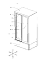
- FIG. 1 is a perspective view of a cold storage according to an embodiment of the present disclosure
- FIG. It is a horizontal cross-sectional view of the cold storage, showing the left side of the lower frame. It is a horizontal cross-sectional view of the cold storage, showing the right side of the lower frame. It is a horizontal cross-sectional view of the cold storage, showing the central portion of the lower frame.
- FIG. 3 is a cross-sectional view taken along line VV shown in FIG. 2; 3 is a cross-sectional view taken along line VI-VI shown in FIG. 2;
- FIG. 4 is a cross-sectional view taken along line VII-VII shown in FIG. 3;
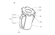
- FIG. Fig. 2 is a perspective view of a drain cap; FIG.
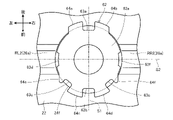
- FIG. 10 is a top view showing a state where the drain cap is attached to the fifth drain port;
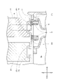
- FIG. 10 is a cross-sectional view taken along line XX shown in FIG. 9;
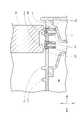
- FIG. 10 is a cross-sectional view taken along line XI-XI shown in FIG. 9;
- FIG. 11 is a top view showing a state in which the drain cap is attached to the sixth drain port;
- FIG. 11 is a top view showing a state in which the drain cap is attached to the sixth drain port;
- the cool box 1 is a chemical cool box that stores drugs at low temperatures.
- the cold storage 1 may be a blood cold storage or a thermostat.
- the cold storage box 1 includes a housing 10, a frame body 20, an inner sliding door 30, an outer sliding door 40, and a machine storage box 50, as shown in FIG.
- the inner sliding door 30 and the outer sliding door 40 are examples of "sliding doors”.
- the housing 10 is formed in the shape of a box having an opening H on the front surface that opens when the sliding doors 30 and 40 are moved.
- a heat insulating material is filled between the outer surface and the inner surface of the housing 10 .
- a space surrounded by the inner surface of the housing 10 is a storage room R1, which is a space in which drugs are stored.
- the frame 20 is provided on the housing 10 so as to surround the opening H.
- the frame body 20 is provided so that the inner sliding door 30 and the outer sliding door 40 can move in the left-right direction.
- the frame body 20 has an upper frame 21 , a lower frame 22 and a vertical frame 23 .
- the lower frame 22 is provided with an inner rail 25 for guiding the inner sliding door 30, an outer rail 26 for guiding the outer sliding door 40, and a drain port 24 to which the drain cap 60 is attached. It is
- the inner rail 25 is composed of a pair of inner rails 25a and 25b.
- the inner rail 25 is provided on the rear side of the lower frame 22 so as to extend in the left-right direction from the left end to the right end.
- the outer rail 26 is composed of a pair of outer rails 26a and 26b.
- the outer rail 26 is provided in front of the inner rail 25 so as to extend in the left-right direction from the left end to the right end of the lower frame 22 .
- the inner rails 25a, 25b and the outer rails 26a, 26b are examples of "rails.”
- the drain port 24 is for discharging condensed water accumulated in the lower frame 22 .
- the drain port 24 is a hole that vertically penetrates the lower frame 22 (FIGS. 5 to 7).
- a plurality of drain ports 24 are formed in the lower frame 22 . Seven drain ports 24 are formed. Needless to say, the number of drain ports 24 is not limited to seven. Needless to say, the position where the drain port 24 is formed is not limited to the position described later.
- the first drain port 24a is formed at the left end of the lower frame 22 at a position dividing the rear inner rail 25a of the inner rails 25.
- the second drain port 24b is formed at the left end of the lower frame 22 at a position where the front inner rail 25b of the inner rails 25 is divided.
- a third drain port 24 c is formed between the inner rail 25 and the outer rail 26 at the left end of the lower frame 22 .
- the fourth drain port 24d is formed between the inner rail 25 and the outer rail 26 at the central portion of the lower frame 22 in the left-right direction.
- the fifth drain port 24e is formed at the center of the lower frame 22 in the left-right direction at a position dividing the front outer rail 26b of the outer rails 26. As shown in FIG.
- the sixth drain port 24f is formed at the right end of the lower frame 22 at a position where the rear outer rail 26a of the outer rails 26 is divided.
- the seventh drain port 24g is formed at the right end of the lower frame 22 at a position where the front outer rail 26b of the outer rails 26 is divided.
- the inner sliding door 30 and the outer sliding door 40 are plate-shaped and open and close the opening H.
- the inner sliding door 30 and the outer sliding door 40 shown in FIG. 1 are positioned at the fully closed position in which the opening H is closed.
- the front surface of the inner sliding door 30 and the front surface of the outer sliding door 40 face the outside of the refrigerator 1 and the rear surface of the inner sliding door 30 and the rear surface of the outer sliding door 40. faces the interior of the cold storage 1, that is, the storage room R1.
- the left end of the inner sliding door 30 is positioned at the left end of the lower frame 22, and the right end of the inner sliding door 30 and the left end of the outer sliding door 40 are positioned at the lower frame 22.
- the right end of the outer sliding door 40 is positioned at the right end of the lower frame 22 .
- the left end of the inner sliding door 30 contacts the left vertical frame 23 .
- the outer sliding door 40 is positioned at the fully closed position, the right end of the outer sliding door 40 contacts the right vertical frame 23 .
- the drain port 24 is formed at the left end, the center in the left-right direction, and the right end of the lower frame 22 . Therefore, the drain port 24 is formed near the ends of the inner sliding door 30 and the outer sliding door 40 .
- the inner sliding door 30 and the outer sliding door 40 have a packing that seals the opening H when positioned at the fully closed position.
- the pair of packings 31 arranged on the inner sliding door 30 and the pair of packings 41 arranged on the outer sliding door 40 are The contact between the inner sliding door 30 and the outer sliding door 40 is sealed.
- the packing (not shown) seals between the inner sliding door 30 and the frame 20 and between the outer sliding door 40 and the frame 20. are arranged at the peripheral edge of the inner sliding door 30 and the peripheral edge of the outer sliding door 40 .
- the opening H is opened.
- the inner sliding door 30 and the outer sliding door 40 have wheels 32,42. Wheels 32 , 42 are attached below the inner sliding door 30 and the outer sliding door 40 .
- the wheels 32 of the inner sliding door 30 are positioned between the pair of inner rails 25a and 25b of the inner rail 25 and rotate as the inner sliding door 30 moves. The rotation of the wheels 32 allows the inner sliding door 30 to move smoothly along the inner rails 25 .
- the wheels 42 of the outer sliding door 40 are positioned between the pair of outer rails 26a and 26b of the outer rail 26 and rotate as the outer sliding door 40 moves. Rotation of the wheels 42 causes the outer sliding door 40 to move smoothly along the outer rails 26 .
- the machine storage 50 is provided on the lower side of the housing 10.
- the internal space of the machine storage shed 50 is the machine room R2.
- a compressor, a condenser, and the like, which form a refrigeration circuit for cooling the storage room R1, are arranged in the machine room R2.
- a drainage guide part 51 is arranged in the machine storage 50 as shown in FIGS. 5 to 7 .
- the drainage guide part 51 receives water discharged from the drainage port 24 and leads it to a drain pan (not shown) arranged in the machine storage 50 .
- a drain pan is located near the compressor. The water led out to the drain pan evaporates due to heat radiation from the compressor.
- FIGS. 9-11 show a drain cap 60 located at the fifth drain port 24e.
- the fifth drain port 24e is formed at a position dividing the outer rail 26b.
- the left outer rail 26b in FIG. 9 is referred to as a first left rail RL1, and the right outer rail 26b in FIG. Described as rail RR1.
- the outer rail 26b shown in FIG. 9 is divided into a first left rail RL1 and a first right rail RR1 arranged to sandwich the fifth drain port 24e.
- the first left rail RL1 is an example of a "first rail.”
- the first right rail RR1 is an example of a "second rail.”
- the fifth drain port 24e is arranged so that its center is located forward of the center of the outer rail 26b in the longitudinal direction.
- the center of the second drain port 24b is located forward of the center of the inner rail 25b in the longitudinal direction, similarly to the fifth drain port 24e.
- the seventh drain port 24g is also arranged so that the center thereof is positioned forward of the longitudinal center of the outer rail 26b.
- the drainage cap 60 has a body portion 61 and a flange portion 62 .
- the body part 61 is a part that is inserted into the drain port 24 .
- the body portion 61 is formed in a tubular shape with both ends opened. 10 and 11 is referred to as a first opening 61a, and the upper opening in FIGS. 10 and 11 is referred to as a second opening 61b.
- the outer diameter of the body portion 61 is formed to be smaller than the inner diameter of the drain port 24 . That is, the body portion 61 is formed to have a gap between it and the drain port 24 .
- the body portion 61 is provided with a pair of claw portions 61c on the peripheral side wall so as to face each other in the radial direction of the body portion 61 .
- the claw portion 61c is provided in each of a third opening 61d and a fourth opening 61e which are rectangular and open in the peripheral wall of the main body portion 61 so as to face each other in the radial direction.
- the claw portion 61c is formed in a rectangular parallelepiped shape protruding toward the second opening 61b side along the axial direction of the body portion 61 from the first opening 61a side portion of each of the third opening 61d and the fourth opening 61e. .
- An inclined portion 61c1, a stepped portion 61c2, and a main body positioning portion 61c3 are provided on the radially outer side of the main body portion 61 in the claw portion 61c.
- the inclined portion 61c1 is formed so as to be inclined from the radially inner side to the radially outer side of the main body portion 61 as it goes from the base end of the claw portion 61c toward the projecting end along the axial direction of the main body portion 61.
- the inclined portion 61c1 is provided so as to come into contact with the periphery of the drain port 24 when the body portion 61 is inserted into the drain port 24. As shown in FIG.
- the body portion 61 When the drain cap 60 is attached to the drain port 24, the body portion 61 is inserted into the drain port 24 from the first opening 61a side.
- the inclined portion 61 c 1 contacts the periphery of the drain port 24 .
- the inclined portion 61c1 is pushed by the peripheral edge of the drain port 24, and the base end portion of the claw portion 61c falls so that the claw portion 61c falls radially inward of the body portion 61. is elastically deformed.
- the inclined portion 61c1 passes through the drain port 24, the shape of the claw portion 61c is restored.
- the stepped portion 61c2 is formed so as to be hooked on the lower surface of the lower frame 22 when the drain cap 60 is attached to the drain port 24. Therefore, the step portion 61c2 can prevent the drain cap 60 from coming off the drain port 24 upward.
- the main body positioning part 61c3 is provided so as to come into contact with the inner peripheral surface of the drain port 24 when the drain cap 60 is attached to the drain port 24. Thereby, the radial position of the body portion 61 with respect to the drain port 24 can be determined.
- the main body positioning portion 61 c 3 positions the main body portion 61 so as to have a gap over the entire circumference of the main body portion 61 with respect to the drain port 24 .
- the flange portion 62 is provided on the second opening 61b side of the body portion 61 .
- the flange portion 62 is formed so as not to contact the inner sliding door 30 and the outer sliding door 40 .
- the flange portion 62 is formed to be symmetrical with respect to a first plane S1 orthogonal to the flange surface 62a (specifically, the upper and lower surfaces of the flange portion 62).
- the first plane S ⁇ b>1 is a plane passing through the axis of the main body portion 61 .
- a notch portion 63 and a facing portion 64 are provided on the flange portion 62 .
- the notch portion 63 is formed in the peripheral portion of the flange portion 62 so as to extend to the radially inner side of the drain port 24 .
- a plurality of notch portions 63 are formed in the flange portion 62 .
- Six cutouts 63 are formed. Needless to say, the number of notches 63 is not limited to six. Furthermore, it goes without saying that the position and shape of the notch 63 are not limited to those described later.
- the first notch portion 63a is formed so that the first portion B1, which is one of the two portions through which the first plane S1 passes, in the peripheral portion of the flange portion 62 is cut out.
- the first notch portion 63a is formed so that a part of the rear end portion of the peripheral edge portion of the flange portion 62 is notched in FIG.
- the first plane S1 is an example of a "plane".
- the second cutout portion 63b is formed so as to cut out a second portion B2, which is the other one of two portions in the peripheral portion of the flange portion 62 through which the first plane S1 passes.
- the second notch portion 63b is formed so that a part of the front end portion of the peripheral portion of the flange portion 62 is notched in FIG.
- the third cutout portion 63c is formed so that a third portion B3 between the first portion B1 and the second portion B2 in the peripheral portion of the flange portion 62 is cut out.
- the third portion B3 is defined by the second portion B2 in the peripheral portion of the flange portion 62 and the second plane S2 passing through the center of the flange surface 62a and perpendicular to the first plane S1. located in the middle part.
- the third notch portion 63c is formed so that the left front end portion of the peripheral portion of the flange portion 62 in FIG. 9 is notched.
- the fourth cutout portion 63d is formed so that a fourth portion B4 between the first portion B1 and the third portion B3 in the peripheral portion of the flange portion 62 is cut out.
- the fourth portion B4 is a portion of the peripheral portion of the flange portion 62 through which the second plane S2 passes.
- the fourth notch portion 63d is formed so that the left end portion of the peripheral portion of the flange portion 62 in FIG. 9 is notched.
- the fifth notch 63e is formed symmetrically with respect to the third notch 63c and the first plane S1. That is, the fifth cutout portion 63e is formed so that the right front end portion of the peripheral portion of the flange portion 62 in FIG. 9 is cut out.
- the sixth notch 63f is formed to be symmetrical to the fourth notch 63d with respect to the first plane S1. That is, the sixth notch portion 63f is formed so that the right end portion of the peripheral portion of the flange portion 62 in FIG. 9 is notched.
- the facing portion 64 is formed on the peripheral edge portion of the flange portion 62 so as to face the peripheral edge portion of the drain port 24 .
- the opposing portion 64 is provided so that the lower surface thereof contacts the upper surface of the lower frame 22 when the drain cap 60 is attached to the drain port 24 .
- the facing portion 64 is in contact with the lower frame 22 to restrict the drain cap 60 from passing downward through the drain port 24 .
- a plurality of facing portions 64 are formed. Six facing portions 64 are formed. Needless to say, the number of facing portions 64 is not limited to six. Furthermore, it goes without saying that the position and shape of the facing portion 64 are not limited to those described later.
- the first facing portion 64a is formed in the counterclockwise direction (counterclockwise direction in FIG. 9) from the first notch portion 63a in the peripheral portion of the flange portion 62 when viewed from the second opening 61b side. there is The first facing portion 64a extends along the first plane S1 and has a curved surface at the rear end with a radius larger than the radius of the drain port 24 when viewed from the second opening 61b side. is formed in
- the second facing portion 64b is formed symmetrically with respect to the first facing portion 64a and the first plane S1.
- the first facing portion 64a and the second facing portion 64b are formed adjacent to the first notch portion 63a.
- the third facing portion 64c is formed between the second cutout portion 63b and the third cutout portion 63c so as to be adjacent to the second cutout portion 63b and the third cutout portion 63c. It is The third facing portion 64c is formed in a fan shape when viewed from the second opening 61b side. The third facing portion 64c is formed at its front end to have a curved surface with a radius larger than the radius of the drain port 24 when viewed from the second opening 61b side.
- the fourth facing portion 64d is formed symmetrically with respect to the third facing portion 64c and the first plane S1.
- the fourth facing portion 64d is formed between the second cutout portion 63b and the fifth cutout portion 63e so as to be adjacent to the second cutout portion 63b and the fifth cutout portion 63e. It is
- the fifth facing portion 64e is formed between the third cutout portion 63c and the fourth cutout portion 63d in the peripheral portion of the flange portion 62. As shown in FIG.
- the fifth facing portion 64e is formed in an approximately triangular shape when viewed from the second opening 61b side. A radial outer surface of the fifth facing portion 64e is formed into a curved surface.
- the fifth facing portion 64e is formed adjacent to the third notch portion 63c.
- the sixth facing portion 64f is formed symmetrically with respect to the fifth facing portion 64e and the first plane S1.
- the sixth facing portion 64f is formed adjacent to the fifth notch portion 63e.
- the drain cap 60 is arranged in the fifth opposite direction so that the first notch 63a faces the inside of the storage (rear side in FIG. 9) relative to the outer rail 26b when attached to the fifth drain port 24e.
- a portion 64e and a sixth facing portion 64f are formed.
- the fifth facing portion 64e and the sixth facing portion 64e are formed.
- the fifth facing portion 64e rides on the first right rail RR1 and the sixth facing portion 64f rides on the first left rail RL1.
- the flange portion 62 is restricted from being arranged such that the first notch portion 63a is directed toward the outside of the cabinet with respect to the outer rail 26b.
- the first opposing portion 64a and the first cutout portion are provided between the first left rail RL1 and the first right rail RR1. 63a and the second facing portion 64b are located.
- the first opposing portion 64a is positioned on the side opposite to the side on the first notch 63a side, It is formed so as to be able to contact the left rail RL1.
- the contact of the first facing portion 64a with the first left rail RL1 restricts the counterclockwise rotation of the flange portion 62 as viewed from above in FIG.
- the second facing portion 64b is provided on the side opposite to the side on the side of the first notch 63a. It is formed so as to be able to contact the right rail RR1. The contact of the second facing portion 64b with the first right rail RR1 restricts the clockwise rotation of the flange portion 62 in the top view of FIG.
- the first opposing portion 64a and the second opposing portion 64b are arranged such that the first notch portion 63a is positioned between the first left rail RL1 and the second opposing portion 64b. It is formed so as to be located in the central portion between the first right rails RR1.
- the first plane S1 is approximately perpendicular to the lateral direction, which is the direction in which the outer rail 26b extends.
- the first notch portion 63a is arranged as described above, so that the second, third, and fifth notch portions 63b , 63c, and 63e are arranged with the flange portion 62 so as to face the outer side of the storage with respect to the outer rail 26b.
- part of the fourth notch 63d and part of the sixth notch 63f are located outside the outer rail 26b.
- the flange portion 62 is arranged so as to face the .
- the first facing portion 64a, the second facing portion 64b, the fifth facing portion 64e, and the sixth facing portion 64f are examples of the "positioning portion.”
- the sixth drain port 24f shown in FIG. 12 is arranged so that its center is positioned at the center of the outer rail 26a in the front-rear direction. 12 is referred to as a second left rail RL2, and the right outer rail 26a in FIG. 12 is referred to as a second right rail RL2. Described as rail RR2.
- the outer rail 26a shown in FIG. 12 is divided into a second left rail RL2 and a second right rail RR2 arranged to sandwich the sixth drain port 24f.
- the second left rail RL2 is an example of a "first rail.”
- the second right rail RR2 is an example of a "second rail.”
- the first notch 63a is directed toward the outside of the outer rail 26a, and the second , 3 and 5 of the flange portion 62 are arranged so that the cutout portions 63b, 63c and 63e of the outer rail 26a are directed toward the inside of the chamber.
- the fifth facing portion 64e is formed so as to be able to come into contact with the second right rail RR2. .
- the contact of the fifth facing portion 64e with the second right rail RR2 restricts the clockwise rotation of the flange portion 62 when viewed from above in FIG.
- the sixth facing portion 64f is formed so as to be able to come into contact with the second left rail RL2. .
- the contact of the sixth facing portion 64f with the second left rail RL2 restricts the counterclockwise rotation of the flange portion 62 when viewed from above in FIG.
- the drain cap 60 when the drain cap 60 is attached to the sixth drain port 24f, the fifth facing portion 64e and the sixth facing portion 64f are aligned with the first notch portion 63a. is positioned at the center between the second left rail RL2 and the second right rail RR2.
- the drain cap 60 can be attached to the sixth drain port 24f so that the flange portion 62 faces in the front-rear direction opposite to the orientation shown in FIG.
- the first notch 63a is directed toward the inner side of the cabinet relative to the outer rail 26a
- the second , 3 and 5 of the flange portion 62 are arranged so that the cutout portions 63b, 63c and 63e of the outer rail 26a are directed toward the outer side of the cabinet.
- the drain cap 60 when the drain cap 60 is attached to the sixth drain port 24f, the fifth facing portion 64e and the sixth facing portion 64f are aligned with the first notch portion 63a. is positioned at the center between the second left rail RL2 and the second right rail RR2.
- the opposing portions 64 of the drain caps 60 arranged at the third and fourth drain ports 24 c and 24 d do not contact the inner rail 25 and the outer rail 26 . Therefore, the direction of the flange portion 62 of the drain caps 60 arranged at the third and fourth drain ports 24c and 24d is not restricted.
- Dew condensation also occurs on the left side surface of the outer sliding door 40 and on the portion of the frame 20 in front of the inner sliding door 30 and the outer sliding door 40 . Therefore, a relatively large amount of condensed water accumulates at the left end, the center in the left-right direction, and the right end of the lower frame 22 .
- Condensed water generated on the left side of the inner sliding door 30 and the frame 20 is discharged from the first to fifth drain ports 24a, 24b, 24c, 24d, and 24e.
- Condensed water generated on the right side of the outer sliding door 40 and the frame 20 is discharged from the fourth to seventh drain ports 24d, 24e, 24f and 24g.
- FIG. 10 shows the condensed water accumulated near the fifth drain port 24e. If the drain cap 60 is not attached to the fifth drain port 24e, the condensed water W may stay on the periphery of the fifth drain port 24e due to surface tension and may not flow into the fifth drain port 24e. .
- the condensed water W on the inner side of the outer rail 26b contacts the first facing portion 64a or the second facing portion 64b. , along the flange portion 62 as indicated by the dashed line in FIG. Part of the condensed water W traveling along the flange portion 62 reaches the inner peripheral surface of the first notch portion 63a and the fifth drain port 24e, and is discharged from the fifth drain port 24e and the drain guide portion 51. .
- Another part of the condensed water W traveling along the flange portion 62 reaches the first notch portion 63a and the outer peripheral surface of the main body portion 61, and by traveling along the main body portion 61, reaches the fifth drain port 24e and thus the outer peripheral surface of the main body portion 61. It is discharged from the drainage guide portion 51 .
- the condensed water W on the outer side of the storage from the outer rail 26b travels along the flange portion 62 by contacting the third to sixth facing portions 64c, 64d, 64e, and 64f. Part of the condensed water W that travels along the flange portion 62 reaches at least one of the second to sixth notch portions 63b, 63c, 63d, 63e, and 63f, and eventually the inner peripheral surface of the fifth drain port 24e. It reaches the fifth drain port 24 e and is discharged from the drain guide portion 51 .
- Another part of the condensed water W traveling along the flange portion 62 is deposited on at least one of the second to sixth notch portions 63b, 63c, 63d, 63e, and 63f, and further on the outer peripheral surface of the main body portion 61.
- the water reaches the main body 61 and is discharged from the fifth drain port 24e and the drain guide portion 51 by extension.
- the left end of the outer sliding door 40 in the fully closed position is positioned above the fifth drain port 24e. Therefore, the condensed water generated at the left end of the outer sliding door 40 may fall on the upper surface of the drain cap 60 . Condensed water that has fallen on the upper surface of the drain cap 60 is discharged from the drain port 24 by running along the inside of the main body 61 .
- the drain cap 60 can discharge the condensed water from the drain port 24 via the notch 63 when the condensed water comes into contact with the facing portion 64 of the flange portion 62 . That is, the drainage cap 60 can improve drainage.
- the body portion 61 is formed to have a gap between it and the drain port 24 . Therefore, the condensed water can be discharged from between the body portion 61 and the drain port 24 .
- the cutout portion 63 is formed so as to cut out to the radially inner side of the drain port 24 . Therefore, the condensed water can be transmitted from the notch 63 to the drain port 24 .
- the flange portion 62 is formed so as to be symmetrical with respect to the first plane S1. Therefore, the drain cap 60 can similarly drain the condensed water on both sides in the direction perpendicular to the first plane S1.
- the first plane S1 is approximately orthogonal to the extending direction of the outer rail 26b as described above. Therefore, the drain cap 60 can similarly drain the condensed water on both sides in the extending direction of the outer rail 26b.
- the first notch portion 63a is formed so that the first portion B1 in the peripheral portion of the flange portion 62 is notched.
- the second notch portion 63b is formed so that the second portion B2 in the peripheral portion of the flange portion 62 is notched.
- the third cutout portion 63c is formed so as to cut out a third portion B3 between the first portion B1 and the second portion B2 in the peripheral edge portion of the flange portion 62 .
- the third portion is defined between the second portion B2 in the peripheral portion of the flange portion 62 and the second plane S2 passing through the center of the flange surface 62a and perpendicular to the first plane S1.
- the fourth cutout portion 63d is formed so as to cut out a fourth portion B4 between the first portion B1 and the third portion B3 in the peripheral edge portion of the flange portion 62 .
- the fifth notch 63e is formed symmetrically with respect to the third notch 63c and the first plane S1.
- the sixth cutout portion 63f is formed symmetrically with respect to the fourth cutout portion 63d and the first plane S1. Therefore, the condensed water around the flange portion 62 can be properly discharged.
- the body portion 61 is formed in a tubular shape with both ends opened. Therefore, the condensed water that has reached the upper surface of the body portion 61 can be discharged from the inside of the body portion 61 to the drain port 24 .
- the drain port 24 is formed at a position near the inner sliding door 30 and the outer sliding door 40 in the closed state on the lower frame 22 .
- a relatively large amount of condensed water tends to accumulate near the inner sliding door 30 and the outer sliding door 40 in the closed state of the lower frame 22 . Therefore, the drain cap 60 attached to the drain port 24 can effectively discharge condensed water accumulated in the vicinity of the inner sliding door 30 and the outer sliding door 40 in the closed state of the lower frame 22 .
- the drain port 24 is formed at a position dividing the outer rail 26b. Therefore, the condensed water on the inner side of the outer rail 26b and the outer side of the outer rail 26b can be drained by one drain port 24 and by extension one drain cap 60.
- FIG. 1 is a diagrammatic representation of the outer rail 26b.
- the first, second, fifth, and sixth opposing portions 64a, 64b, 64e, and 64f contact the outer rail 26b to form the first notch portion 63a and the second, third, and fifth notch portions 63b.
- , 63c and 63e are directed toward the inner side of the cabinet relative to the outer rail 26b, and the other of the first notch 63a and the second, third and fifth notch 63b, 63c and 63e is directed toward the outer rail 26b. It is formed so as to face the outside of the chamber.
- the flange portion 62 directs the dew condensation water accumulated on the inner side of the outer rail 26b to one of the first notch portion 63a and the second, third, and fifth notch portions 63b, 63c, and 63e, and also to the outer rail. Condensed water accumulated on the outside of the chamber 26b can be transmitted to the other of the first notch 63a and the second, third, and fifth notches 63b, 63c, and 63e.
- first and second facing portions 64a and 64b position the first notch portion 63a at the central portion of the first left rail RL1 and the second right rail RR2. Therefore, as shown in FIG. 9, when the drain port 24 is formed so that the center of the drain port 24 is located forward of the center of the outer rail 26b in the front-rear direction, the first cutout portion 63a is positioned at the first position. 3 and 5 cutouts 63c and 63e can be arranged closer to the outer rail 26b.
- the third and fifth notches 63c, 63e can be positioned closer to outer rail 26b than first cutout 63a. Therefore, the condensed water accumulated along the outer rail 26 b can easily reach the notch 63 and be discharged from the drain port 24 .
- the orientation of the flange portion 62 is selected and arranged. can do. Therefore, the orientation of the flange portion 62 can be selected based on the location and amount of condensed water.
- the facing portion 64 may be formed so as to have a gap between it and the peripheral portion of the drain port 24 .
- a protrusion (not shown) may be provided on the lower surface of the facing portion 64 .
- a gap is formed between the lower side surface of the facing portion 64 and the upper side surface of the lower frame 22 by contacting the tip of the protrusion with the upper side surface of the lower frame 22 .
- the condensed water W travels along the outer shape of the opposing portion 64 and thus along the outer shape of the notch portion 63 .
- a portion of the dew condensation water W traveling along the cutout portion 63 reaches the base of the cutout portion 63 and the outer peripheral surface of the main body portion 61 and travels along the main body portion 61 to reach the fifth drain port 24e and the drain guide portion 51.
- discharged from Another part of the dew condensation water W traveling along the notch 63 reaches the inner peripheral surface of the first notch 63a and the fifth drain port 24e, and reaches the fifth drain port 24e and the drain guide portion. 51 is discharged.
- Part of the condensed water W travels through the gap between the lower surface of the facing portion 64 and the upper surface of the lower frame 22 . That is, the condensed water W coming into contact with the facing portion 64 travels along the notch portion 63, reaches the outer peripheral surface of the notch portion 63 and the main body portion 61, travels along the main body portion 61, and reaches the peripheral edges of the drain cap 60 and the drain port 24. Condensed water can be efficiently discharged from the gap between the parts.
- the present disclosure can be widely used for cold storage devices such as medical coolers, blood coolers, and thermostats.
- Reference Signs List 1 cool box 10 housing 20 frame 24 drain port 25a inner rail (rail) 25b inner rail (rail) 26a outer rail (rail) 26b outer rail (rail) 30 inner sliding door (sliding door) 40 Outer sliding door (sliding door) 60 drain cap 61 main body 62 flange 62a flange surface 63a first notch (notch) 63b 2nd notch 63c 3rd notch 63d 4th notch 63e 5th notch 64 facing part 64a first facing part 64b second facing part 64c third facing part 64d Fourth facing portion 64e Fifth facing portion 64f Sixth facing portion B1 First portion B2 Second portion B3 Third portion B4 Fourth portion S1 First plane (plane) S2 Second plane W Condensed water
Landscapes
- Engineering & Computer Science (AREA)
- Mechanical Engineering (AREA)
- Chemical & Material Sciences (AREA)
- Combustion & Propulsion (AREA)
- Physics & Mathematics (AREA)
- Thermal Sciences (AREA)
- General Engineering & Computer Science (AREA)
- Removal Of Water From Condensation And Defrosting (AREA)
Abstract
排水キャップは、排水口に挿入される本体部と、本体部に設けられ、周縁部に切り欠き部、および、排水口の周縁部に対向する対向部を有するフランジ部と、を備える。
Description
本開示は、排水キャップおよび保冷庫に関する。
特許文献1には引違いサッシが開示されている。引違いサッシは、サッシ枠の下枠に溜まった水を複数の排水口から外部に排水する。複数の排水口の一つには、室内側排水装置が配置されている。室内側排水装置は、外気の室内側への侵入を防止する排水弁を有している。複数の排水口の他の一つには、排水キャップが配置されている。排水キャップは、排水口へゴミ等が侵入することを防止する格子が形成されている。
薬剤等を低温にて保管する保冷庫は、保管室内と保管室外との温度差が比較的大きいため、保管室を開閉する戸に結露が発生しやすい。よって、戸が配置される枠体には、結露水が比較的多く溜まる。したがって、結露水の排水性を向上させる必要性がある。
本開示は、排水性を向上させる排水キャップおよび保冷庫を提供することを目的とする。
前記目的を達成するために、本開示における排水キャップは、排水口に挿入される本体部と、本体部に設けられ、周縁部に切り欠き部、および、排水口の周縁部に対向する対向部を有するフランジ部と、を備える。
また、本開示における保冷庫は、上記の排水キャップと、排水口が形成され、引戸が配置される枠体と、を備える保冷庫であって、排水口は、閉状態にある引戸の端部の近傍となる位置に形成されている。
本開示の排水キャップおよび保冷庫によれば、排水性を向上させることができる。
以下、本開示の保冷庫および排水キャップの実施形態について、図面を参照しながら説明する。なお、以下では、図1の矢印で示すように、図1における左下側および右上側をそれぞれ保冷庫1の前方および後方とし、同じく左上側および右下側をそれぞれ保冷庫1の左方および右方とし、同じく上側および下側をそれぞれ保冷庫1の上方および下方として説明する。
保冷庫1は、薬剤を低温にて保管する薬品保冷庫である。なお、保冷庫1は、血液保冷庫または恒温器であってもよい。保冷庫1は、図1に示されるように、筐体10、枠体20、内側引戸30、外側引戸40、および、機械収納庫50を備えている。内側引戸30および外側引戸40は、「引戸」の一例である。
筐体10は前面に引戸30,40の移動により開口する開口Hを有する箱状に形成されている。筐体10の外側面と内側面との間には、断熱材が充填されている。筐体10の内側面に囲まれた空間は、保管室R1であり、薬剤が収容される空間である。
枠体20は、開口Hを取り囲むように筐体10に設けられている。枠体20は、内側引戸30および外側引戸40が左右方向に移動可能に設けられている。枠体20は、上枠21、下枠22および縦枠23を備えている。
図2から図7に示されるように、下枠22には、内側引戸30を案内する内側レール25、外側引戸40を案内する外側レール26、および、排水キャップ60が取り付けられる排水口24が設けられている。
内側レール25は、一対の内レール25a,25bによって構成されている。内側レール25は、下枠22の後側にて左端部から右端部にかけて左右方向に沿って延びるように設けられている。外側レール26は、一対の外レール26a,26bによって構成されている。外側レール26は、内側レール25より前方にて、下枠22の左端部から右端部にかけて左右方向に沿って延びるように設けられている。内レール25a,25bおよび外レール26a,26bは、「レール」の一例である。
排水口24は、下枠22に溜まる結露水を排出するものである。排水口24は、下枠22を上下方向に沿って貫通する穴である(図5から図7)。排水口24は、下枠22に複数形成されている。排水口24は、7個形成されている。なお、排水口24の個数が7個に限定されないことは言うまでもない。なお、排水口24が形成されている位置は、後述する位置に限定されないことは言うまでもない。
図2および図5に示されるように、第1の排水口24aは、下枠22の左端部において内側レール25のうち後側の内レール25aを分割する位置に形成されている。第2の排水口24bは、下枠22の左端部における、内側レール25のうち前側の内レール25bを分割する位置に形成されている。第3の排水口24cは、下枠22の左端部において内側レール25と外側レール26との間に形成されている。
図2および図6に示されるように、第4の排水口24dは、下枠22の左右方向中央部において内側レール25と外側レール26との間に形成されている。第5の排水口24eは、下枠22の左右方向中央部における、外側レール26のうち前側の外レール26bを分割する位置に形成されている。
図3および図7に示されるように、第6の排水口24fは、下枠22の右端部における、外側レール26のうち後側の外レール26aを分割する位置に形成されている。第7の排水口24gは、下枠22の右端部における、外側レール26のうち前側の外レール26bを分割する位置に形成されている。
内側引戸30および外側引戸40は、板状に形成され、開口Hを開閉するものである。図1に示される内側引戸30および外側引戸40は、開口Hを閉状態にする全閉位置に位置している。内側引戸30および外側引戸40が全閉位置に位置する場合、内側引戸30の前面および外側引戸40の前面は保冷庫1の外部に面し、かつ、内側引戸30の後面および外側引戸40の後面は保冷庫1の内部すなわち保管室R1に面する。
内側引戸30および外側引戸40が全閉位置に位置する場合、内側引戸30の左端部が下枠22の左端部に位置し、内側引戸30の右端部および外側引戸40の左端部が下枠22の左右方向中央部に位置し、外側引戸40の右端部が下枠22の右端部に位置する。また、内側引戸30が全閉位置に位置する場合、内側引戸30の左端が左側の縦枠23に接触する。外側引戸40が全閉位置に位置する場合、外側引戸40の右端が右側の縦枠23に接触する。
上記のように、排水口24は、下枠22の左端部、左右方向中央部および右端部に形成されている。よって、排水口24は、内側引戸30および外側引戸40の端部の近傍に形成されている。
また、内側引戸30および外側引戸40は、全閉位置に位置する場合に開口Hを密閉するパッキンを有している。図4に示されるように、内側引戸30および外側引戸40が全閉位置に位置する場合に、内側引戸30に配置された一対のパッキン31と外側引戸40に配置された一対のパッキン41とが接触することで、内側引戸30と外側引戸40との間が密閉される。また、内側引戸30および外側引戸40が全閉位置に位置する場合に、内側引戸30と枠体20との間、および、外側引戸40と枠体20との間を密閉するパッキン(図示なし)が内側引戸30の周縁部および外側引戸40の周縁部に配置されている。
内側引戸30および外側引戸40が全閉位置に位置する状態から内側引戸30が右方向に移動、または、外側引戸40が左方向に移動することで、開口Hが開状態になる。
さらに、図2から図6に示されるように、内側引戸30および外側引戸40は、車輪32,42を有する。車輪32,42は、内側引戸30および外側引戸40の下方に取り付けられている。
内側引戸30の車輪32は、内側レール25の一対の内レール25a,25bの間に位置し、内側引戸30の移動に応じて回転する。車輪32が回転することで、内側引戸30が内側レール25に沿って円滑に移動する。
外側引戸40の車輪42は、外側レール26の一対の外レール26a,26bの間に位置し、外側引戸40の移動に応じて回転する。車輪42が回転することで、外側引戸40が外側レール26に沿って円滑に移動する。
機械収納庫50は、筐体10の下側に設けられている。機械収納庫50の内部空間は、機械室R2である。機械室R2には、保管室R1内を冷却する冷凍回路を構成する圧縮機および凝縮器などが配置されている。
また、機械収納庫50には、図5から図7に示されるように、排水案内部51が配置されている。排水案内部51は、排水口24から排出された水を受けて、機械収納庫50内に配置されたドレンパン(図示なし)に導出するものである。ドレンパンは圧縮機の近傍に配置されている。ドレンパンに導出された水は、圧縮機からの放熱によって蒸発する。
図8に示される排水キャップ60は、排水口24それぞれに配置されている。図9から図11には、第5の排水口24eに配置された排水キャップ60が示されている。上述したように、第5の排水口24eは、外レール26bを分割する位置に形成されている。以下、第5の排水口24eによって分割された外レール26bのうち、図9の左側の外レール26bを第1の左レールRL1と記載し、図9の右側の外レール26bを第1の右レールRR1と記載する。換言すれば、図9に示される外レール26bは、第5の排水口24eを挟むように配置された第1の左レールRL1および第1の右レールRR1に分割されている。第1の左レールRL1は、「第1のレール」の一例である。第1の右レールRR1は、「第2のレール」の一例である。
第5の排水口24eは、中心が外レール26bの前後方向の中心よりも前方に位置するように配置されている。なお、第2の排水口24bも、第5の排水口24eと同様に、中心が内レール25bの前後方向の中心よりも前方に位置するように配置されている。また、第7の排水口24gも、第5の排水口24eと同様に、中心が外レール26bの前後方向の中心よりも前方に位置するように配置されている。
排水キャップ60は、本体部61およびフランジ部62を備えている。
本体部61は、排水口24に挿入される部位である。本体部61は両端を開口する筒状に形成されている。以下、図10および図11の下側の開口を第1開口61aとし、図10および図11の上側の開口を第2開口61bと記載する。本体部61の外径は、排水口24の内径よりも小さくなるように形成されている。つまり、本体部61は、排水口24との間に隙間を有するように形成されている。本体部61は、周側壁に一対の爪部61cが本体部61の径方向に互いに対向するように設けられている。
爪部61cは、本体部61の周側壁において、径方向に互いに対向するように矩形状に開口する第3開口61dおよび第4開口61eそれぞれに設けられている。爪部61cは、第3開口61dおよび第4開口61eそれぞれにおける第1開口61a側の部位から本体部61の軸線方向に沿って第2開口61b側に向けて突出する直方体状に形成されている。爪部61cにおける本体部61の径方向外側には、傾斜部61c1、段部61c2および本体位置決め部61c3が設けられている。
傾斜部61c1は、爪部61cの基端から本体部61の軸線方向に沿って突出端に向かうにしたがって、本体部61の径方向内側から径方向外側に向かうように傾斜するように形成されている。本体部61が排水口24に挿入されるときに、傾斜部61c1が排水口24の周縁に接触するように設けられている。
排水キャップ60が排水口24に取り付けられる場合、本体部61が第1開口61a側から排水口24に挿入される。本体部61が排水口24に挿入されると、傾斜部61c1が排水口24の周縁に接触する。さらに、本体部61が排水口24に押し込まれると、傾斜部61c1が排水口24の周縁に押されて、爪部61cが本体部61の径方向内側に倒れるように爪部61cの基端部が弾性変形する。傾斜部61c1が排水口24と通り抜けると、爪部61cの形状が復元する。
段部61c2は、排水キャップ60が排水口24に取り付けられた状態において、下枠22の下側面に引っ掛かるように形成されている。よって、段部61c2は、排水キャップ60が排水口24から上方に外れることを防止することができる。
本体位置決め部61c3は、排水キャップ60が排水口24に取り付けられた状態において、排水口24の内周面に接触するように設けられている。これにより、排水口24に対する本体部61の径方向の位置を定めることができる。本体位置決め部61c3は、本体部61を、排水口24との間に本体部61の全周に亘って隙間を有するように位置決めする。
フランジ部62は、本体部61の第2開口61b側に設けられている。フランジ部62は、内側引戸30および外側引戸40に接触しないように形成されている。また、フランジ部62は、フランジ面62a(具体的にはフランジ部62の上面および下面)に直交する第1の平面S1に対して面対称となるように形成されている。第1の平面S1は、本体部61の軸線を通る平面である。
フランジ部62は、切り欠き部63および対向部64が設けられている。
切り欠き部63は、フランジ部62の周縁部に、排水口24の径方向内側まで切り欠かれるように形成されている。切り欠き部63は、フランジ部62に複数形成されている。切り欠き部63は、6つ形成されている。なお、切り欠き部63の個数が6つに限定されないことは言うまでもない。さらに、切り欠き部63の位置および形状を後述する位置および形状に限定されないことは言うまでもない。
第1の切り欠き部63aは、フランジ部62の周縁部における、第1の平面S1が通る2つの部位の1つである第1の部位B1が切り欠かれるように形成されている。第1の切り欠き部63aは、図9において、フランジ部62の周縁部における後端部の一部が切り欠かれるように形成されている。第1の平面S1は、「平面」の一例である。
第2の切り欠き部63bは、フランジ部62の周縁部における、第1の平面S1が通る2つの部位の他の1つである第2の部位B2が切り欠かれるように形成されている。第2の切り欠き部63bは、図9において、フランジ部62の周縁部における前端部の一部が切り欠かれるように形成されている。
第3の切り欠き部63cは、フランジ部62の周縁部における、第1の部位B1と第2の部位B2の間の第3の部位B3が切り欠かれるように形成されている。第3の部位B3は、具体的には、フランジ部62の周縁部における、第2の部位B2と、フランジ面62aの中心を通り且つ第1の平面S1に直行する第2の平面S2との間の部位に定められている。第3の切り欠き部63cは、図9において、フランジ部62の周縁部における左前端部が切り欠かれるように形成されている。
第4の切り欠き部63dは、フランジ部62の周縁部における第1の部位B1と第3の部位B3との間の第4の部位B4が切り欠かれるように形成されている。第4の部位B4は、フランジ部62の周縁部における、第2の平面S2が通る部位である。第4の切り欠き部63dは、図9において、フランジ部62の周縁部における左端部が切り欠かれるように形成されている。
第5の切り欠き部63eは、第3の切り欠き部63cと第1の平面S1に対して対称となるように形成されている。つまり、第5の切り欠き部63eは、図9において、フランジ部62の周縁部における右前端部が切り欠かれるように形成されている。
第6の切り欠き部63fは、第4の切り欠き部63dと第1の平面S1に対して対称となるように形成されている。つまり、第6の切り欠き部63fは、図9において、フランジ部62の周縁部における右端部が切り欠かれるように形成されている。
対向部64は、フランジ部62の周縁部に、排水口24の周縁部と対向するように形成されている。対向部64は、排水キャップ60が排水口24に取り付けられた状態において、下面が下枠22の上面に接触するように設けられている。対向部64が下枠22に接触することで、排水キャップ60が排水口24から下方に通り抜けることが規制される。
対向部64は、複数形成されている。対向部64は、6つ形成されている。なお、対向部64の個数が6つに限定されないことは言うまでもない。さらに、対向部64の位置および形状を後述する位置および形状に限定されないことは言うまでもない。
第1の対向部64aは、フランジ部62の周縁部における第1の切り欠き部63aから、第2開口61b側から見て反時計回り方向(図9において反時計回り方向)側に形成されている。第1の対向部64aは、第1の平面S1に沿って延びるように、かつ、後端に、第2開口61b側から見て排水口24の半径より大きい半径に設定された曲面を有するように形成されている。
第2の対向部64bは、第1の対向部64aと第1の平面S1に対して対称となるように形成されている。第1の対向部64aおよび第2の対向部64bは、第1の切り欠き部63aと隣接するように形成されている。
第3の対向部64cは、第2の切り欠き部63bと第3の切り欠き部63cとの間にて、第2の切り欠き部63bおよび第3の切り欠き部63cに隣接するように形成されている。第3の対向部64cは、第2開口61b側から見て、およそ扇状に形成されている。第3の対向部64cは、前端に、第2開口61b側から見て排水口24の半径より大きい半径に設定された曲面を有するように形成されている。
第4の対向部64dは、第3の対向部64cと第1の平面S1に対して対称となるように形成されている。第4の対向部64dは、第2の切り欠き部63bと第5の切り欠き部63eとの間にて、第2の切り欠き部63bおよび第5の切り欠き部63eに隣接するように形成されている。
第5の対向部64eは、フランジ部62の周縁部における第3の切り欠き部63cと第4の切り欠き部63dとの間に形成されている。第5の対向部64eは、第2開口61b側から見ておよそ三角状に形成されている。第5の対向部64eの径方向外側面は、曲面に形成されている。第5の対向部64eは、第3の切り欠き部63cと隣接するように形成されている。
第6の対向部64fは、第5の対向部64eと第1の平面S1に対して対称となるように形成されている。第6の対向部64fは、第5の切り欠き部63eと隣接するように形成されている。
排水キャップ60は、第5の排水口24eに取り付けられている状態において、第1の切り欠き部63aが外レール26bよりも庫内側(図9において後方側)に向くように、第5の対向部64eおよび第6の対向部64fが形成されている。第1の切り欠き部63aが外レール26bよりも庫外(図9において前方側)側に向くように、本体部61を排水口24に挿入すると、第5の対向部64eおよび第6の対向部64fは、第5の対向部64eが第1の右レールRR1に、かつ、第6の対向部64fが第1の左レールRL1に乗り上げる。つまり、フランジ部62は、第1の切り欠き部63aが外レール26bよりも庫外側に向くように配置されることが規制される。
また、排水キャップ60が第5の排水口24eに取り付けられている状態において、第1の左レールRL1と第1の右レールRR1との間に第1の対向部64a、第1の切り欠き部63aおよび第2の対向部64bが位置する。
さらに、排水キャップ60が第5の排水口24eに取り付けられている状態において、第1の対向部64aは、第1の切り欠き部63a側の側面とは反対側の側面にて、第1の左レールRL1に接触可能に形成されている。第1の対向部64aが第1の左レールRL1に接触することで、フランジ部62が図9の上面視において反時計回り方向に回転することが規制される。
また、排水キャップ60が第5の排水口24eに取り付けられている状態において、第2の対向部64bは、第1の切り欠き部63a側の側面とは反対側の側面にて、第1の右レールRR1に接触可能に形成されている。第2の対向部64bが第1の右レールRR1に接触することで、フランジ部62が図9の上面視において時計回り方向に回転することが規制される。
さらに、排水キャップ60が第5の排水口24eに取り付けられている状態において、第1の対向部64aおよび第2の対向部64bは、第1の切り欠き部63aを第1の左レールRL1および第1の右レールRR1の間の中央部に位置させるように形成されている。なお、排水キャップ60が第4の排水口24dに取り付けられている状態において、第1の平面S1は、外レール26bが延びる方向である左右方向におよそ直交している。
また、排水キャップ60が第5の排水口24eに取り付けられている状態において、上記のように、第1の切り欠き部63aが配置されることにより、第2,3,5の切り欠き部63b,63c,63eは、外レール26bよりも庫外側に向くようにフランジ部62が配置される。
さらに、排水キャップ60が第5の排水口24eに取り付けられている状態において、第4の切り欠き部63dの一部および第6の切り欠き部63fの一部は、外レール26bよりも庫外側に向くようにフランジ部62が配置される。第1の対向部64a、第2の対向部64b、第5の対向部64eおよび第6の対向部64fは、「位置決め部」の一例である。
また、図12に示される第6の排水口24fは、中心が外レール26aの前後方向の中心に位置するように配置されている。以下、第6の排水口24fによって分割された外レール26aのうち、図12の左側の外レール26aを第2の左レールRL2と記載し、図12の右側の外レール26aを第2の右レールRR2と記載する。換言すれば、図12に示される外レール26aは、第6の排水口24fを挟むように配置された第2の左レールRL2および第2の右レールRR2に分割されている。第2の左レールRL2は、「第1のレール」の一例である。第2の右レールRR2は、「第2のレール」の一例である。
図12に示されるように、排水キャップ60が第6の排水口24fに取り付けられている状態において、第1の切り欠き部63aが外レール26aよりも庫外側に向くように、かつ、第2,3,5の切り欠き部63b,63c,63eが外レール26aよりも庫内側に向くようにフランジ部62が配置される。
また、図12に示されるように、排水キャップ60が第6の排水口24fに取り付けられている状態において、第5の対向部64eは、第2の右レールRR2に接触可能に形成されている。第5の対向部64eが第2の右レールRR2に接触することで、フランジ部62が図12の上面視において時計回り方向に回転することが規制される。
さらに、図12に示されるように、排水キャップ60が第6の排水口24fに取り付けられている状態において、第6の対向部64fは、第2の左レールRL2に接触可能に形成されている。第6の対向部64fが第2の左レールRL2に接触することで、フランジ部62が図12の上面視において反時計回り方向に回転することが規制される。
また、図12に示されるように、排水キャップ60が第6の排水口24fに取り付けられている状態において、第5の対向部64eおよび第6の対向部64fは、第1の切り欠き部63aを第2の左レールRL2および第2の右レールRR2の間の中央部に位置させるように形成されている。
さらに、図13に示されるように、フランジ部62が図12に示される向きとは前後方向の反対に向くように、排水キャップ60を第6の排水口24fに取り付けることができる。図13に示されるように、排水キャップ60が第6の排水口24fに取り付けられている状態において、第1の切り欠き部63aが外レール26aよりも庫内側に向くように、かつ、第2,3,5の切り欠き部63b,63c,63eが外レール26aよりも庫外側に向くようにフランジ部62が配置される。
また、図13に示されるように、排水キャップ60が第6の排水口24fに取り付けられている状態において、第5の対向部64eが第2の左レールRL2に接触することで、フランジ部62が図13の上面視において時計回り方向に回転することが規制される。
さらに、図13に示されるように、排水キャップ60が第6の排水口24fに取り付けられている状態において、第6の対向部64fが第2の右レールRR2に接触することで、フランジ部62が図13の上面視において反時計回り方向に回転することが規制される。
また、図13に示されるように、排水キャップ60が第6の排水口24fに取り付けられている状態において、第5の対向部64eおよび第6の対向部64fは、第1の切り欠き部63aを第2の左レールRL2および第2の右レールRR2の間の中央部に位置させるように形成されている。
なお、第3,4の排水口24c,24dに配置されている排水キャップ60は、対向部64が内側レール25および外側レール26に接触しない。よって、第3,4の排水口24c,24dに配置されている排水キャップ60は、フランジ部62の向きが規制されない。
次に、排水口24における結露水の排出について説明する。保管室R1の温度が低下すると保管室R1の温度と外気温度との差が大きくなる。また、保冷庫1内の冷気によって内側引戸30、外側引戸40および枠体20の温度が低下する。よって、主に、内側引戸30の外側面および外側引戸40の外側面に結露が発生する。発生した結露水は、内側引戸30および外側引戸40を伝って下枠22に溜まる。
また、結露は、外側引戸40の左側面、および、枠体20における内側引戸30および外側引戸40より前方の部位にも、結露が発生する。よって、結露水は、下枠22における左端部、左右方向の中央部、右端部に、比較的多く溜まる。
内側引戸30および枠体20の左側にて発生した結露水は、第1から第5の排水口24a,24b,24c,24d,24eから排出される。外側引戸40および枠体20の右側にて発生した結露水は、第4から第7の排水口24d,24e,24f,24gから排出される。
図10には、第5の排水口24eの近傍に溜まっている結露水が示されている。第5の排水口24eに排水キャップ60が取り付けられていない場合、結露水Wは、表面張力によって第5の排水口24eの周縁に留まることで、第5の排水口24eに流入しない場合がある。
一方、第5の排水口24eに排水キャップ60が取り付けられている場合、外レール26bより庫内側にある結露水Wは、第1の対向部64aまたは第2の対向部64bに接触することで、図10にて破線にて示されるように、フランジ部62を伝う。フランジ部62を伝う結露水Wの一部は、第1の切り欠き部63aひいては第5の排水口24eの内周面に到達し、第5の排水口24eひいては排水案内部51から排出される。また、フランジ部62を伝う結露水Wの他の一部は、第1の切り欠き部63aひいては本体部61の外周面に到達し、本体部61を伝うことで、第5の排水口24eひいては排水案内部51から排出される。
また、外レール26bより庫外側にある結露水Wは、第3から第6の対向部64c,64d,64e、64fに接触することで、フランジ部62を伝う。フランジ部62を伝う結露水Wの一部は、第2から第6の切り欠き部63b,63c,63d,63e,63fの少なくともいずれか1つ、ひいては第5の排水口24eの内周面に到達し、第5の排水口24eひいては排水案内部51から排出される。また、フランジ部62を伝う結露水Wの他の一部は、第2から第6の切り欠き部63b,63c,63d,63e,63fの少なくともいずれか1つ、ひいては本体部61の外周面に到達し、本体部61を伝うことで、第5の排水口24eひいては排水案内部51から排出される。
また、図4に示すように、第5の排水口24eの上方には、全閉位置にある外側引戸40の左端部が位置する。よって、外側引戸40の左端部にて発生した結露水が排水キャップ60の上面に落下する場合がある。排水キャップ60の上面に落下した結露水は、本体部61の内側を伝うことで、排水口24から排出される。
上記のように、排水キャップ60は、結露水がフランジ部62の対向部64に接触することで、切り欠き部63を介して、結露水を排水口24から排出させることができる。つまり、排水キャップ60は、排水性を向上させることができる。
また、本体部61は、排水口24との間に隙間を有するように形成されている。よって、本体部61と排水口24との間から結露水を排出することができる。
そして、切り欠き部63は、排水口24の径方向内側まで切り欠かれるように形成されている。よって、結露水を切り欠き部63から排水口24に伝わらせることができる。
また、フランジ部62は、第1の平面S1に対して面対称となるように形成されている。よって、排水キャップ60は、第1の平面S1に直行する方向の両側にある結露水それぞれを同様に排出することができる。排水キャップ60が排水口24に取り付けられている場合、上記のように第1の平面S1は、外レール26bの延びる方向におよそ直交している。よって、排水キャップ60は、外レール26bの延びる方向の両側にある結露水それぞれを同様に排出できる。
そして、第1の切り欠き部63aは、フランジ部62の周縁部における第1の部位B1が切り欠かれるように形成されている。第2の切り欠き部63bは、フランジ部62の周縁部における第2の部位B2が切り欠かれるように形成されている。第3の切り欠き部63cは、フランジ部62の周縁部における第1の部位B1と第2の部位B2との間の第3の部位B3が切り欠かれるように形成されている。第3の部位は、フランジ部62の周縁部における第2の部位B2と、フランジ面62aの中心を通り且つ第1の平面S1に直行する第2の平面S2との間の部位に定められている。第4の切り欠き部63dは、フランジ部62の周縁部における第1の部位B1と第3の部位B3との間の第4の部位B4が切り欠かれるように形成されている。第5の切り欠き部63eは、第3の切り欠き部63cと第1の平面S1に対して対称となるように形成されている。また、第6の切り欠き部63fは、第4の切り欠き部63dと第1の平面S1に対して対称となるように形成されている。よって、フランジ部62の周囲にある結露水を適切に排出できる。
また、本体部61は両端を開口する筒状に形成されている。よって、本体部61の上面に到達した結露水を、本体部61の内側から排水口24に排出できる。
そして、排水口24は、下枠22において閉状態にある内側引戸30および外側引戸40の近傍となる位置に形成されている。結露水は、上記のように、下枠22において閉状態にある内側引戸30および外側引戸40の近傍に比較的多く溜まりやすい。よって、排水口24に取り付けられた排水キャップ60は、下枠22において閉状態にある内側引戸30および外側引戸40の近傍に溜まる結露水を効果的に排出できる。
また、排水口24は、外レール26bを分割する位置に形成されている。よって、外レール26bの庫内側および外レール26bの庫外側にある結露水を、1つの排水口24ひいては1つの排水キャップ60によって排出することができる。
そして、第1,2,5,6の対向部64a,64b,64e,64fは、外レール26bに接触することで、第1の切り欠き部63aおよび第2,3,5の切り欠き部63b,63c,63eの一方が外レール26bよりも庫内側に向くように、かつ、第1の切り欠き部63aおよび第2,3,5の切り欠き部63b,63c,63eの他方が外レール26bよりも庫外側に向くように形成されている。よって、フランジ部62は、外レール26bの庫内側に溜まる結露水を第1の切り欠き部63aおよび第2,3,5の切り欠き部63b,63c,63eの一方に、かつ、および外レール26bの庫外側に溜まる結露水を第1の切り欠き部63aおよび第2,3,5の切り欠き部63b,63c,63eの他方に伝わらせることができる。
また、第1,2の対向部64a,64bは、第1の切り欠き部63aを第1の左レールRL1および第2の右レールRR2の中央部に位置させる。よって、図9に示されるように、排水口24の中心が外レール26bの前後方向中央より前方に位置するように排水口24が形成されている場合に、第1の切り欠き部63aを第3,5の切り欠き部63c,63eよりも外レール26bの近くに配置することができる。また、図12,13に示されるように、排水口24の中心が外レール26bの前後方向中央に位置するように排水口24が形成されている場合、第3,5の切り欠き部63c,63eを第1の切り欠き部63aよりも外レール26bの近くに配置することができる。よって、外レール26bを伝って溜まっている結露水を切り欠き部63に容易に到達させて排水口24から排出することができる。
さらに、図12,13に示されるように、排水口24の中心が外レール26bの前後方向中央に位置するように排水口24が形成されている場合、フランジ部62の向きを選択して配置することができる。よって、結露水が溜まる場所および量に基づいて、フランジ部62の向きを選択することができる。
本開示は、これまでに説明した実施の形態に限定されるものではない。本開示の主旨を逸脱しない限り、各種変形を本実施の形態に施したものや、異なる実施の形態における構成要素を組み合わせて構築される形態も、本開示の範囲内に含まれる。
例えば、対向部64は、排水口24の周縁部との間に隙間を有するように形成されていてもよい。例えば、対向部64の下側面に突起部(不図示)を設けてもよい。突起部の先端が下枠22の上側面に接触することで、対向部64の下側面と下枠22の上側面との間に隙間ができる。
結露水が対向部64に接触すると、毛細管現象により、結露水Wが、対向部64の外形を伝い、ひいては切り欠き部63の外形に沿って伝う。切り欠き部63を伝う結露水Wの一部は、切り欠き部63の根本ひいては本体部61の外周面に到達し、本体部61を伝うことで、第5の排水口24eひいては排水案内部51から排出される。また、切り欠き部63を伝う結露水Wの他の一部は、第1の切り欠き部63aひいては第5の排水口24eの内周面に到達し、第5の排水口24eひいては排水案内部51から排出される。なお、結露水Wの一部は、対向部64の下側面と下枠22の上側面との間の隙間を伝う。つまり、対向部64に接触した結露水Wが切り欠き部63を伝い、切り欠き部63ひいては本体部61の外周面に到達し、本体部61を伝うと、排水キャップ60と排水口24の周縁部との間の隙間から、結露水を効率よく排出することができる。
2021年2月9日出願の特願2021-019073の日本出願に含まれる明細書、特許請求の範囲、図面および要約書の開示内容は、すべて本願に援用される。
本開示は、薬用保冷庫、血液保冷庫、および、恒温器などの保冷装置に広く利用可能である。
1 保冷庫
10 筐体
20 枠体
24 排水口
25a 内レール(レール)
25b 内レール(レール)
26a 外レール(レール)
26b 外レール(レール)
30 内側引戸(引戸)
40 外側引戸(引戸)
60 排水キャップ
61 本体部
62 フランジ部
62a フランジ面
63a 第1の切り欠き部(切り欠き部)
63b 第2の切り欠き部
63c 第3の切り欠き部
63d 第4の切り欠き部
63e 第5の切り欠き部
64 対向部
64a 第1の対向部
64b 第2の対向部
64c 第3の対向部
64d 第4の対向部
64e 第5の対向部
64f 第6の対向部
B1 第1の部位
B2 第2の部位
B3 第3の部位
B4 第4の部位
S1 第1の平面(平面)
S2 第2の平面
W 結露水
Claims (13)
- 排水口に挿入される本体部と、
前記本体部に設けられ、周縁部に切り欠き部、および、前記排水口の周縁部に対向する対向部を有するフランジ部と、を備える、
排水キャップ。 - 前記本体部は、前記排水口との間に隙間を有するように形成されている、
請求項1に記載の排水キャップ。 - 前記切り欠き部は、前記排水口の径方向内側まで切り欠かれるように形成されている、
請求項1または2に記載の排水キャップ。 - 前記フランジ部は、フランジ面に直交する平面に対して面対称となるように形成されている、
請求項1から3の何れか1項に記載の排水キャップ。 - 前記切り欠き部は、
前記フランジ部の周縁部における、前記平面が通る2つの部位である第1の部位および第2の部位の少なくとも一方が切り欠かれるように形成されているとともに、
前記フランジ部の周縁部における、前記第1の部位と前記第2の部位の間の第3の部位が切り欠かれるように形成されている、
請求項4に記載の排水キャップ。 - 前記フランジ部の周縁部における前記第3の部位は、前記フランジ部の周縁部における、前記第2の部位と、フランジ面の中心を通り且つ前記平面に直行する第2の平面との間の部位に定められている、
請求項5に記載の排水キャップ。 - 前記切り欠き部は、前記フランジ部の周縁部における前記第1の部位と前記第3の部位との間の第4の部位が切り欠かれるように形成されている、
請求項5または6に記載の排水キャップ。 - 前記本体部は、両端を開口する筒状に形成されている、
請求項1から7の何れか1項に記載の排水キャップ。 - 前記対向部は、前記排水口の周縁部との間に隙間を有するように形成されている、
請求項1から8の何れか1項に記載の排水キャップ。 - 請求項1から9の何れか1項に記載の排水キャップと、
前記排水口が形成され、引戸が配置される枠体と、を備える保冷庫であって、
前記排水口は、閉状態にある前記引戸の端部の近傍となる位置に形成されている、
保冷庫。 - 請求項1から9の何れか1項に記載の排水キャップと、
前記排水口および引戸を案内するレールが形成されている枠体と、を備える保冷庫であって、
前記排水口は、前記レールを分割する位置に形成されている、
保冷庫。 - 請求項5から7の何れか1項に記載の排水キャップと、
前記排水口および引戸を案内するレールが形成されている枠体と、を備える保冷庫であって、
前記排水口は、前記レールを分割する位置に形成され、
前記フランジ部は、前記レールに接触することで、前記切り欠き部の少なくとも1つが前記レールよりも庫内側に向くように、かつ、前記切り欠き部の他の少なくとも1つが前記レールよりも庫外側に向くようにフランジ部を位置させる位置決め部をさらに有する、
保冷庫。 - 前記レールは、前記排水口を挟むように配置された第1のレールおよび第2のレールに分割されており、
前記位置決め部は、前記第1のレールおよび前記第2のレールの一方に接触することで、前記切り欠き部を前記第1のレールおよび前記第2のレールの間の中央部に位置させる、
請求項12に記載の保冷庫。
Priority Applications (4)
| Application Number | Priority Date | Filing Date | Title |
|---|---|---|---|
| EP22752657.1A EP4180611A4 (en) | 2021-02-09 | 2022-02-02 | DRAINAGE CAP AND COLD RETENTION |
| JP2022580579A JP7374357B2 (ja) | 2021-02-09 | 2022-02-02 | 排水キャップおよび保冷庫 |
| CN202280006059.4A CN116234968A (zh) | 2021-02-09 | 2022-02-02 | 排水罩及冷库 |
| US18/108,355 US20230184479A1 (en) | 2021-02-09 | 2023-02-10 | Drainage cap and cold storage |
Applications Claiming Priority (2)
| Application Number | Priority Date | Filing Date | Title |
|---|---|---|---|
| JP2021-019073 | 2021-02-09 | ||
| JP2021019073 | 2021-02-09 |
Related Child Applications (1)
| Application Number | Title | Priority Date | Filing Date |
|---|---|---|---|
| US18/108,355 Continuation US20230184479A1 (en) | 2021-02-09 | 2023-02-10 | Drainage cap and cold storage |
Publications (1)
| Publication Number | Publication Date |
|---|---|
| WO2022172830A1 true WO2022172830A1 (ja) | 2022-08-18 |
Family
ID=82838810
Family Applications (1)
| Application Number | Title | Priority Date | Filing Date |
|---|---|---|---|
| PCT/JP2022/004128 WO2022172830A1 (ja) | 2021-02-09 | 2022-02-02 | 排水キャップおよび保冷庫 |
Country Status (5)
| Country | Link |
|---|---|
| US (1) | US20230184479A1 (ja) |
| EP (1) | EP4180611A4 (ja) |
| JP (1) | JP7374357B2 (ja) |
| CN (1) | CN116234968A (ja) |
| WO (1) | WO2022172830A1 (ja) |
Citations (10)
| Publication number | Priority date | Publication date | Assignee | Title |
|---|---|---|---|---|
| JPS5873894U (ja) * | 1981-11-13 | 1983-05-19 | 三協アルミニウム工業株式会社 | 結露水排出装置 |
| JPS58142280U (ja) * | 1982-03-23 | 1983-09-26 | ミサワホ−ム株式会社 | 結露水排水装置 |
| JPS59172677U (ja) * | 1983-05-09 | 1984-11-17 | トヨタ車体株式会社 | 車体の排水装置 |
| JPH10339559A (ja) * | 1997-06-04 | 1998-12-22 | Hoshizaki Electric Co Ltd | ショーケースの下枠構造 |
| JP3404308B2 (ja) | 1998-12-28 | 2003-05-06 | トステム株式会社 | 引違いサッシ |
| KR200331749Y1 (ko) * | 2003-07-02 | 2003-11-01 | 이영수 | 창틀의 빗물 역류방지구조 |
| KR100725497B1 (ko) * | 2006-04-27 | 2007-06-08 | 삼성전자주식회사 | 김치냉장고 |
| JP2018068836A (ja) * | 2016-11-01 | 2018-05-10 | 福島工業株式会社 | リーチイン型の貯蔵庫 |
| JP2021019073A (ja) | 2019-07-19 | 2021-02-15 | キヤノン株式会社 | リソグラフィー装置及びクリーニング方法 |
| JP2021059922A (ja) * | 2019-10-08 | 2021-04-15 | Ykk Ap株式会社 | 排水装置及び建具 |
Family Cites Families (3)
| Publication number | Priority date | Publication date | Assignee | Title |
|---|---|---|---|---|
| EP1835339B1 (fr) | 2006-03-15 | 2012-05-16 | Rolex S.A. | Procédé de fabrication par technologie de type liga d'une structure métallique monocouche ou multicouche, et structure obtenue |
| CN106225395B (zh) * | 2015-11-30 | 2019-05-31 | 青岛海尔特种电冰柜有限公司 | 具有前后推拉门的冷柜 |
| KR102478735B1 (ko) * | 2018-03-12 | 2022-12-19 | 엘지전자 주식회사 | 냉장고 |
-
2022
- 2022-02-02 CN CN202280006059.4A patent/CN116234968A/zh active Pending
- 2022-02-02 WO PCT/JP2022/004128 patent/WO2022172830A1/ja unknown
- 2022-02-02 EP EP22752657.1A patent/EP4180611A4/en active Pending
- 2022-02-02 JP JP2022580579A patent/JP7374357B2/ja active Active
-
2023
- 2023-02-10 US US18/108,355 patent/US20230184479A1/en active Pending
Patent Citations (10)
| Publication number | Priority date | Publication date | Assignee | Title |
|---|---|---|---|---|
| JPS5873894U (ja) * | 1981-11-13 | 1983-05-19 | 三協アルミニウム工業株式会社 | 結露水排出装置 |
| JPS58142280U (ja) * | 1982-03-23 | 1983-09-26 | ミサワホ−ム株式会社 | 結露水排水装置 |
| JPS59172677U (ja) * | 1983-05-09 | 1984-11-17 | トヨタ車体株式会社 | 車体の排水装置 |
| JPH10339559A (ja) * | 1997-06-04 | 1998-12-22 | Hoshizaki Electric Co Ltd | ショーケースの下枠構造 |
| JP3404308B2 (ja) | 1998-12-28 | 2003-05-06 | トステム株式会社 | 引違いサッシ |
| KR200331749Y1 (ko) * | 2003-07-02 | 2003-11-01 | 이영수 | 창틀의 빗물 역류방지구조 |
| KR100725497B1 (ko) * | 2006-04-27 | 2007-06-08 | 삼성전자주식회사 | 김치냉장고 |
| JP2018068836A (ja) * | 2016-11-01 | 2018-05-10 | 福島工業株式会社 | リーチイン型の貯蔵庫 |
| JP2021019073A (ja) | 2019-07-19 | 2021-02-15 | キヤノン株式会社 | リソグラフィー装置及びクリーニング方法 |
| JP2021059922A (ja) * | 2019-10-08 | 2021-04-15 | Ykk Ap株式会社 | 排水装置及び建具 |
Non-Patent Citations (1)
| Title |
|---|
| See also references of EP4180611A4 |
Also Published As
| Publication number | Publication date |
|---|---|
| EP4180611A4 (en) | 2024-01-10 |
| JPWO2022172830A1 (ja) | 2022-08-18 |
| US20230184479A1 (en) | 2023-06-15 |
| EP4180611A1 (en) | 2023-05-17 |
| CN116234968A (zh) | 2023-06-06 |
| JP7374357B2 (ja) | 2023-11-06 |
Similar Documents
| Publication | Publication Date | Title |
|---|---|---|
| US10551127B2 (en) | Heat exchanger | |
| JP4620663B2 (ja) | キャビネット冷蔵システム | |
| US9267725B2 (en) | Refrigerator | |
| WO2013046580A1 (ja) | 冷蔵庫 | |
| JP2009079837A (ja) | 冷蔵庫 | |
| WO2022172830A1 (ja) | 排水キャップおよび保冷庫 | |
| WO2022190734A1 (ja) | 保冷庫 | |
| JP2014163633A (ja) | 冷却器、および冷蔵庫 | |
| WO2010016196A1 (ja) | 冷蔵庫 | |
| JP6490221B2 (ja) | 冷蔵庫 | |
| JP4065420B2 (ja) | 直冷式冷蔵庫 | |
| WO2019151511A1 (ja) | 冷却貯蔵庫 | |
| JP2006078053A (ja) | 冷蔵庫 | |
| KR20070027307A (ko) | 냉장고의 부압 방지 장치 | |
| JP7361945B2 (ja) | 冷蔵庫 | |
| JP2007078282A (ja) | 冷蔵庫 | |
| WO2019175965A1 (ja) | 冷蔵庫 | |
| JP2001056174A (ja) | 冷蔵庫 | |
| JP2007040654A (ja) | 冷凍装置 | |
| KR20070107355A (ko) | 냉장고 | |
| CN110542261A (zh) | 具有真空隔离面板的冷却装置 | |
| JP2001056175A (ja) | 冷蔵庫 | |
| JP4086737B2 (ja) | 冷蔵庫 | |
| JP2009168277A (ja) | 冷却貯蔵庫 | |
| JP2011058681A (ja) | ダンパ装置およびダンパ装置を備えた冷蔵庫 |
Legal Events
| Date | Code | Title | Description |
|---|---|---|---|
| 121 | Ep: the epo has been informed by wipo that ep was designated in this application |
Ref document number: 22752657 Country of ref document: EP Kind code of ref document: A1 |
|
| ENP | Entry into the national phase |
Ref document number: 2022580579 Country of ref document: JP Kind code of ref document: A |
|
| ENP | Entry into the national phase |
Ref document number: 2022752657 Country of ref document: EP Effective date: 20230210 |
|
| NENP | Non-entry into the national phase |
Ref country code: DE |