WO2022168387A1 - レーダ設置角度調整支援装置及びコンピュータプログラム - Google Patents
レーダ設置角度調整支援装置及びコンピュータプログラム Download PDFInfo
- Publication number
- WO2022168387A1 WO2022168387A1 PCT/JP2021/041375 JP2021041375W WO2022168387A1 WO 2022168387 A1 WO2022168387 A1 WO 2022168387A1 JP 2021041375 W JP2021041375 W JP 2021041375W WO 2022168387 A1 WO2022168387 A1 WO 2022168387A1
- Authority
- WO
- WIPO (PCT)
- Prior art keywords
- angle
- display
- installation
- radar
- target value
- Prior art date
- Legal status (The legal status is an assumption and is not a legal conclusion. Google has not performed a legal analysis and makes no representation as to the accuracy of the status listed.)
- Ceased
Links
Images




Classifications
-
- G—PHYSICS
- G01—MEASURING; TESTING
- G01S—RADIO DIRECTION-FINDING; RADIO NAVIGATION; DETERMINING DISTANCE OR VELOCITY BY USE OF RADIO WAVES; LOCATING OR PRESENCE-DETECTING BY USE OF THE REFLECTION OR RERADIATION OF RADIO WAVES; ANALOGOUS ARRANGEMENTS USING OTHER WAVES
- G01S7/00—Details of systems according to groups G01S13/00, G01S15/00, G01S17/00
- G01S7/02—Details of systems according to groups G01S13/00, G01S15/00, G01S17/00 of systems according to group G01S13/00
- G01S7/40—Means for monitoring or calibrating
- G01S7/4004—Means for monitoring or calibrating of parts of a radar system
- G01S7/4026—Antenna boresight
-
- G—PHYSICS
- G01—MEASURING; TESTING
- G01S—RADIO DIRECTION-FINDING; RADIO NAVIGATION; DETERMINING DISTANCE OR VELOCITY BY USE OF RADIO WAVES; LOCATING OR PRESENCE-DETECTING BY USE OF THE REFLECTION OR RERADIATION OF RADIO WAVES; ANALOGOUS ARRANGEMENTS USING OTHER WAVES
- G01S13/00—Systems using the reflection or reradiation of radio waves, e.g. radar systems; Analogous systems using reflection or reradiation of waves whose nature or wavelength is irrelevant or unspecified
- G01S13/02—Systems using reflection of radio waves, e.g. primary radar systems; Analogous systems
- G01S13/50—Systems of measurement based on relative movement of target
- G01S13/58—Velocity or trajectory determination systems; Sense-of-movement determination systems
- G01S13/581—Velocity or trajectory determination systems; Sense-of-movement determination systems using transmission of interrupted pulse modulated waves and based upon the Doppler effect resulting from movement of targets
- G01S13/582—Velocity or trajectory determination systems; Sense-of-movement determination systems using transmission of interrupted pulse modulated waves and based upon the Doppler effect resulting from movement of targets adapted for simultaneous range and velocity measurements
-
- G—PHYSICS
- G01—MEASURING; TESTING
- G01S—RADIO DIRECTION-FINDING; RADIO NAVIGATION; DETERMINING DISTANCE OR VELOCITY BY USE OF RADIO WAVES; LOCATING OR PRESENCE-DETECTING BY USE OF THE REFLECTION OR RERADIATION OF RADIO WAVES; ANALOGOUS ARRANGEMENTS USING OTHER WAVES
- G01S13/00—Systems using the reflection or reradiation of radio waves, e.g. radar systems; Analogous systems using reflection or reradiation of waves whose nature or wavelength is irrelevant or unspecified
- G01S13/02—Systems using reflection of radio waves, e.g. primary radar systems; Analogous systems
- G01S13/50—Systems of measurement based on relative movement of target
- G01S13/58—Velocity or trajectory determination systems; Sense-of-movement determination systems
- G01S13/583—Velocity or trajectory determination systems; Sense-of-movement determination systems using transmission of continuous unmodulated waves, amplitude-, frequency-, or phase-modulated waves and based upon the Doppler effect resulting from movement of targets
- G01S13/584—Velocity or trajectory determination systems; Sense-of-movement determination systems using transmission of continuous unmodulated waves, amplitude-, frequency-, or phase-modulated waves and based upon the Doppler effect resulting from movement of targets adapted for simultaneous range and velocity measurements
-
- G—PHYSICS
- G01—MEASURING; TESTING
- G01S—RADIO DIRECTION-FINDING; RADIO NAVIGATION; DETERMINING DISTANCE OR VELOCITY BY USE OF RADIO WAVES; LOCATING OR PRESENCE-DETECTING BY USE OF THE REFLECTION OR RERADIATION OF RADIO WAVES; ANALOGOUS ARRANGEMENTS USING OTHER WAVES
- G01S13/00—Systems using the reflection or reradiation of radio waves, e.g. radar systems; Analogous systems using reflection or reradiation of waves whose nature or wavelength is irrelevant or unspecified
- G01S13/86—Combinations of radar systems with non-radar systems, e.g. sonar, direction finder
-
- G—PHYSICS
- G01—MEASURING; TESTING
- G01S—RADIO DIRECTION-FINDING; RADIO NAVIGATION; DETERMINING DISTANCE OR VELOCITY BY USE OF RADIO WAVES; LOCATING OR PRESENCE-DETECTING BY USE OF THE REFLECTION OR RERADIATION OF RADIO WAVES; ANALOGOUS ARRANGEMENTS USING OTHER WAVES
- G01S13/00—Systems using the reflection or reradiation of radio waves, e.g. radar systems; Analogous systems using reflection or reradiation of waves whose nature or wavelength is irrelevant or unspecified
- G01S13/88—Radar or analogous systems specially adapted for specific applications
- G01S13/91—Radar or analogous systems specially adapted for specific applications for traffic control
-
- G—PHYSICS
- G08—SIGNALLING
- G08G—TRAFFIC CONTROL SYSTEMS
- G08G1/00—Traffic control systems for road vehicles
- G08G1/01—Detecting movement of traffic to be counted or controlled
- G08G1/04—Detecting movement of traffic to be counted or controlled using optical or ultrasonic detectors
-
- G—PHYSICS
- G01—MEASURING; TESTING
- G01S—RADIO DIRECTION-FINDING; RADIO NAVIGATION; DETERMINING DISTANCE OR VELOCITY BY USE OF RADIO WAVES; LOCATING OR PRESENCE-DETECTING BY USE OF THE REFLECTION OR RERADIATION OF RADIO WAVES; ANALOGOUS ARRANGEMENTS USING OTHER WAVES
- G01S13/00—Systems using the reflection or reradiation of radio waves, e.g. radar systems; Analogous systems using reflection or reradiation of waves whose nature or wavelength is irrelevant or unspecified
- G01S13/88—Radar or analogous systems specially adapted for specific applications
- G01S13/91—Radar or analogous systems specially adapted for specific applications for traffic control
- G01S13/92—Radar or analogous systems specially adapted for specific applications for traffic control for velocity measurement
-
- G—PHYSICS
- G01—MEASURING; TESTING
- G01S—RADIO DIRECTION-FINDING; RADIO NAVIGATION; DETERMINING DISTANCE OR VELOCITY BY USE OF RADIO WAVES; LOCATING OR PRESENCE-DETECTING BY USE OF THE REFLECTION OR RERADIATION OF RADIO WAVES; ANALOGOUS ARRANGEMENTS USING OTHER WAVES
- G01S7/00—Details of systems according to groups G01S13/00, G01S15/00, G01S17/00
- G01S7/02—Details of systems according to groups G01S13/00, G01S15/00, G01S17/00 of systems according to group G01S13/00
- G01S7/027—Constructional details of housings, e.g. form, type, material or ruggedness
-
- G—PHYSICS
- G01—MEASURING; TESTING
- G01S—RADIO DIRECTION-FINDING; RADIO NAVIGATION; DETERMINING DISTANCE OR VELOCITY BY USE OF RADIO WAVES; LOCATING OR PRESENCE-DETECTING BY USE OF THE REFLECTION OR RERADIATION OF RADIO WAVES; ANALOGOUS ARRANGEMENTS USING OTHER WAVES
- G01S7/00—Details of systems according to groups G01S13/00, G01S15/00, G01S17/00
- G01S7/02—Details of systems according to groups G01S13/00, G01S15/00, G01S17/00 of systems according to group G01S13/00
- G01S7/04—Display arrangements
- G01S7/06—Cathode-ray tube displays or other two dimensional or three-dimensional displays
- G01S7/062—Cathode-ray tube displays or other two dimensional or three-dimensional displays in which different colours are used
Definitions
- the present disclosure relates to a radar installation angle adjustment support device and a computer program.
- This application claims priority based on Japanese application No. 2021-015579 filed on February 3, 2021, and incorporates all the contents described in the Japanese application.
- Patent Document 1 discloses an axis adjusting device that adjusts the axis of an in-vehicle radar mounted on a vehicle.
- a radar installation angle adjustment support device includes a display device, and a support screen for supporting adjustment of the installation angle of an infrastructure radar that detects an object existing in a target area by transmitting and receiving radio waves on the display device.
- a display control unit configured to display, the support screen includes a target value display unit configured to display a target value of the installation angle of the infrastructure radar; and a target value display unit configured to display the installation angle of the infrastructure radar.
- a detected angle display unit configured to display the installation angle detected by the angle sensor that detects the angle; the target value displayed on the target value display unit; a determination result display unit that displays a determination result of determining whether or not the angle difference from the installation angle is within the predetermined set range, wherein the display control unit controls whether the angle difference is within the predetermined set range. , the angle based on the angle difference is displayed on the support screen.
- a computer program is a computer program for causing a computer including a display device to execute processing for supporting adjustment of an installation angle of an infrastructure radar that detects an object existing in a target area by transmitting and receiving radio waves. wherein the processing includes processing for causing the computer to display a support screen for supporting adjustment of an installation angle of the infrastructure radar on the display device, wherein the support screen is for installation of the infrastructure radar.
- a target value display unit for displaying a target value of an angle
- a detected angle display unit for displaying the installation angle detected by an angle sensor for detecting the installation angle of the infrastructure radar
- a determination result display unit that displays a determination result of determining whether or not the angle difference between the target value and the installation angle displayed on the detection angle display unit is within a predetermined set range; If the angle difference is not within the predetermined set range, the angle based on the angle difference is displayed on the support screen.
- the present disclosure can be realized not only as a radar installation angle adjustment support device having the characteristic configuration as described above, but also as a display control device for controlling a characteristic screen display in the radar installation angle adjustment support device.
- it can be implemented as a radar installation angle adjustment support method having steps of characteristic processing of the radar installation angle adjustment support device, or as a computer program that causes a computer to execute the above method.
- FIG. 11 is a diagram showing another example of a support screen according to the first embodiment;
- FIG. 11 is a perspective view showing an example of an appearance composition of a radar concerning a 2nd embodiment.
- FIG. 9 is a flow chart showing an example of the operation procedure of the radar installation angle adjustment support device according to the second embodiment; It is a figure which shows an example of the support screen which concerns on 2nd Embodiment.
- FIG. 11 is a diagram showing another example of a support screen according to the second embodiment; FIG.
- Radars are also used for traffic monitoring at intersections, roads, and the like. Radars for traffic monitoring (hereinafter also referred to as “infrared radars”) are installed at intersections or roads by construction workers, and the angles of the installed radars are adjusted by coordinators. At the time of installation by the construction worker, the power source is not connected to the radar, and the construction worker does not have knowledge about adjusting the angle of the radar, so adjustment by the construction worker is difficult. The installed radar is turned on in the adjustment stage, and the person in charge of adjustment checks the output and adjusts the angle so that the irradiation axis points in an appropriate direction. However, the radars installed by the construction staff have different angles, and the optimum angle differs depending on the installation location. was complicated.
- the radar installation angle adjustment support device includes a display device and a support screen for supporting the adjustment of the installation angle of an infrastructure radar that detects objects existing in a target area by transmitting and receiving radio waves.
- a display control unit configured to display the support screen, the target value display unit configured to display a target value of the installation angle of the infrastructure radar; a detected angle display section configured to display the installation angle detected by the angle sensor that detects the installation angle; the target value displayed on the target value display section; and the target value displayed on the detected angle display section.
- a determination result display unit that displays a determination result of determining whether or not the angle difference from the installation angle is within a predetermined setting range, and the display control unit controls whether the angle difference is within the predetermined setting range.
- the angle based on the angle difference is displayed on the support screen.
- the user can adjust the installation angle of the infrastructure radar by checking the angle based on the angle difference on the support screen. Therefore, it is possible to assist the user in adjusting the installation angle of the infrastructure radar.
- the installation angle includes at least one of the horizontal angle, depression angle, and roll angle of the infrastructure radar, and the display control unit controls at least one of the horizontal angle, depression angle, and roll angle of the infrastructure radar. may be displayed on the detection angle display unit. This can assist in adjusting at least one of the horizontal angle, depression angle, and roll angle of the infrastructure radar.
- the angle based on the angular difference may include an angle for correcting at least one of horizontal angle, depression angle, and roll angle of the infrastructure radar.
- the display control unit may cause the support screen to display the angle for correcting at least one of a horizontal angle, a depression angle, and a roll angle of the infrastructure radar. Accordingly, the user can appropriately correct at least one of the horizontal angle, depression angle, and roll angle of the infrastructure radar by checking the angle based on the angle difference.
- the radar installation angle adjustment support device further includes a receiving unit configured to receive angle data indicating the angle detected by the angle sensor, and the display control unit controls the angle detected by the receiving unit.
- a receiving unit configured to receive angle data indicating the angle detected by the angle sensor
- the display control unit controls the angle detected by the receiving unit.
- the display of the angle based on the angular difference is updated, and when the angular difference changes so as to be included in the predetermined set range, the display of the determination result display unit is changed to the angular difference. may be switched to affirmative information indicating that the angle difference is included in the set range. Accordingly, the user can easily and appropriately adjust the installation angle by correcting the installation angle of the infrastructure radar according to the support screen until the display on the determination result display unit switches from the angle based on the angle difference to the positive information. be able to.
- the display color for displaying the angle based on the angular difference and the display color for displaying the positive information may be different from each other. Thereby, the user can easily confirm the switching from the angle based on the angle difference to the positive information in the determination result display section.
- the support screen further includes an installation height display section configured to display the installation height of the infrastructure radar, and the display control section controls the installation height displayed on the installation height display section.
- the target value of the installation angle calculated based on the installation height may be displayed on the target value display section. This makes it possible to present the user with an appropriate target value for the installation angle according to the installation height of the infrastructure radar.
- the support screen includes an installation position information display unit configured to display installation position information indicating the installation position of the infrastructure radar, and a target position indicating the target value of the radio wave irradiation position of the infrastructure radar.
- a target position information display unit configured to display information, wherein the display control unit controls the installation position information displayed on the installation position information display unit and the target position information display unit to display the information.
- the target value of the installation angle calculated based on the target position information obtained and the installation height displayed on the installation height display unit may be displayed on the target value display unit.
- the display control unit may cause the installation position information display unit to display the installation position information indicating the position detected by the position sensor that detects the position of the infrastructure radar. This makes it possible to determine the target value of the installation angle of the infrastructural radar using accurate infrastructural radar installation position information detected by the position sensor.
- a computer program is a computer that causes a computer equipped with a display device to execute processing that supports adjustment of the installation angle of an infrastructure radar that detects objects existing in a target area by transmitting and receiving radio waves.
- the program wherein the processing includes processing for causing the computer to display a support screen for supporting adjustment of the installation angle of the infrastructure radar on the display device, wherein the support screen is the infrastructure radar.
- a target value display section for displaying a target value of an installation angle
- a detection angle display section for displaying the installation angle detected by an angle sensor that detects the installation angle of the radar for infrastructure, and the target value displayed on the target value display section.
- a determination result display unit that displays a determination result of determining whether the angle difference between the target value and the installation angle displayed on the detection angle display unit is within a predetermined setting range;
- the angle based on the angle difference is displayed on the support screen. The user can adjust the installation angle of the infrastructure radar by checking the angle based on the angle difference on the support screen. Therefore, it is possible to assist the user in adjusting the installation angle of the infrastructure radar.
- the installation angle includes at least one of the horizontal angle, depression angle, and roll angle of the infrastructure radar, and the process of displaying the support screen on the display device includes the horizontal angle and depression angle of the infrastructure radar. , and roll angle may be displayed on the detected angle display unit. This can assist in adjusting at least one of the horizontal angle, depression angle, and roll angle of the infrastructure radar.
- the angle based on the angle difference includes an angle for correcting at least one of the horizontal angle, depression angle, and roll angle of the infrastructure radar, and processing for displaying the support screen on the display device may cause the support screen to display the angle for correcting at least one of a horizontal angle, a depression angle, and a roll angle of the infrastructure radar. Accordingly, the user can appropriately correct at least one of the horizontal angle, depression angle, and roll angle of the infrastructure radar by checking the angle based on the angle difference.
- the process of displaying the support screen on the display device updates the display of the angle based on the angle difference each time the angle data indicating the angle detected by the angle sensor is given, and the angle difference changes to the predetermined angle. including processing for switching the display of the determination result display unit from the angle based on the angle difference to affirmative information indicating that the angle difference is included in the set range when the setting range of It's okay. Accordingly, the user can easily and appropriately adjust the installation angle by correcting the installation angle of the infrastructure radar according to the support screen until the display on the determination result display unit switches from the angle based on the angle difference to the positive information. be able to.
- a display color for displaying the angle based on the angle difference and a display color for displaying the affirmative information may be different from each other. Thereby, the user can easily confirm the switching from the angle based on the angle difference to the positive information in the determination result display section.
- the support screen further includes an installation height display section that displays the installation height of the infrastructure radar, and the process of displaying the support screen on the display device is displayed on the installation height display section.
- the target value of the installation angle calculated based on the installation height may be displayed on the target value display section. This makes it possible to present the user with an appropriate target value for the installation angle according to the installation height of the infrastructure radar.
- the support screen includes an installation position information display unit that displays installation position information indicating the installation position of the infrastructure radar, and a target position information display that displays the target value of the radio wave irradiation position of the infrastructure radar. and a position information display unit, wherein the process of displaying the support screen on the display device includes: the installation position information displayed in the installation position information display unit; The target value of the installation angle calculated based on the position information and the installation height displayed on the installation height display section may be displayed on the target value display section.
- the installation position information indicating the position detected by the position sensor that detects the position of the infrastructure radar may be displayed on the installation position information display unit. good. This makes it possible to determine the target value of the installation angle of the infrastructural radar using accurate infrastructural radar installation position information detected by the position sensor.
- FIG. 1 is a diagram showing a usage example of a radar according to an embodiment.
- the radar 100 according to this embodiment is a radio wave radar for traffic monitoring (infrastructure radar).
- the radar 100 is attached to an arm 200 (see FIG. 2) or the like provided at an intersection or road.
- the radar 100 is a millimeter wave radar and a radio wave sensor.
- the radar 100 irradiates a target area 300 on the road with radio waves (millimeter waves) and receives the reflected waves to detect an object (for example, a vehicle V) within the target area 300 . More specifically, the radar 100 can detect the distance to the vehicle V traveling on the road, the speed of the vehicle V, and the horizontal angle of the position of the vehicle V with respect to the radio wave irradiation axis of the radar.
- the radar 100 is installed so that the direction of the radio wave irradiation axis (the method indicated by the dashed line in FIG. 1; hereinafter referred to as the "reference direction") faces the target area 300. If the reference direction does not face the target area 300 correctly, the object within the target area 300 cannot be accurately detected by the radar 100 . For this reason, in the present embodiment, the angle of the radar 100 is adjusted so that the reference direction faces the target area 300 using a radar installation angle adjustment support device as described below.
- FIG. 2 is a perspective view showing an example of the external configuration of the radar 100 according to the first embodiment.
- the radar 100 has a transmitting/receiving surface 101 for transmitting/receiving millimeter waves.
- the reference direction is the normal direction of the transmission/reception surface 101 .
- the radar 100 incorporates at least one transmitting antenna and multiple (for example, two) receiving antennas (not shown).
- the radar 100 transmits modulated waves, which are millimeter waves, from a transmitting antenna through a transmitting/receiving surface 101 .
- the modulated wave hits an object and is reflected, and the receiving antenna receives the reflected wave.
- the radar 100 performs signal processing on the transmitted wave signal and the received wave signal by a signal processing circuit (not shown) to obtain the distance to the object, the angle at which the object exists (hereinafter referred to as "position of the object"), and the speed of the object. To detect.
- the radar 100 is configured so that the installation angle can be adjusted.
- the radar 100 includes a radar body 102 , a depression angle adjuster 103 , a horizontal angle adjuster 104 and a roll angle adjuster 105 .
- the radar main body 102 is formed in a box shape, and the depression angle adjusting portion 103 is attached to the side surface of the radar main body 102 .
- the depression angle adjusting portion 103 includes a pair of arms 103a and a connecting portion 103b connecting the pair of arms 103a.
- Each of the pair of arms 103 a is rotatable about a horizontal axis parallel to the transmitting/receiving surface 101 on both side surfaces of the radar body 102 .
- the radar body 102 is rotatable about the horizontal axis by the depression angle adjusting section 103, whereby the depression angle of the radar body 102 is adjusted.
- the connecting portion 103 b is connected to the roll angle adjusting portion 105 .
- the roll angle adjusting portion 105 includes a lower member 105a and an upper member 105b, and the lower member 105a and the upper member 105b are rotatable about a horizontal rotation axis extending in a direction perpendicular to the longitudinal direction of the connecting portion 103b. is.
- the lower member 105a is fixed to the upper surface of the connecting portion 103b.
- the radar main body 102 connected to the roll angle adjusting section 105 via the depression angle adjusting section 103 is rotatable about the horizontal rotation axis by the roll angle adjusting section 105, whereby the roll angle of the radar main body 102 is adjusted. be done.
- the upper member 105 b of the roll angle adjusting section 105 is connected to the horizontal angle adjusting section 104 .
- the horizontal angle adjuster 104 is fixed to a pole to be installed.
- the horizontal angle adjuster 104 is rotatable about the vertical axis on the upper surface of the upper member 105b.
- the radar main body 102 connected to the horizontal angle adjusting section 104 via the depression angle adjusting section 103 and the roll angle adjusting section 105 can be rotated about the vertical axis by the horizontal angle adjusting section 104, thereby adjusting the horizontal angle of the radar main body 102. angle is adjusted.
- An angle sensor 150 is provided on the radar body 102 .
- the angle sensor 150 can detect the horizontal angle, depression angle, and roll angle of the radar body 102 .
- the angle sensor 150 is connected to the radar installation angle adjustment support device 400 by wire or wirelessly. Data of the detected value (angle) of the angle sensor 150 (hereinafter referred to as “angle data”) is transmitted to the radar installation angle adjustment support device 400 .
- the radar installation angle adjustment support device 400 can display a support screen including the horizontal angle, depression angle, and roll angle detected by the angle sensor 150 on the display device.
- the support screen includes target values for the horizontal angle, depression angle, and roll angle of the radar 100 . The user can adjust the angle of the radar 100 while checking the support screen.
- FIG. 3 is a block diagram showing an example of the configuration of the radar installation angle adjustment support device according to the first embodiment.
- the radar installation angle adjustment support device 400 is configured by a portable information terminal such as a smart phone, tablet, or portable computer.
- the radar installation angle adjustment support device 400 includes a processor 401, a nonvolatile memory 402, a volatile memory 403, a graphic controller 404, a display device 405, an input device 406, and a communication interface (communication I/F) 407. including.
- the volatile memory 403 is a semiconductor memory such as SRAM (Static Random Access Memory) or DRAM (Dynamic Random Access Memory).
- the nonvolatile memory 402 is, for example, a flash memory, a hard disk, a ROM (Read Only Memory), or the like.
- the nonvolatile memory 402 stores an angle adjustment support program 409 which is a computer program and data used for executing the angle adjustment support program 409 .
- the radar installation angle adjustment support device 400 is configured with a computer, and each function of the radar installation angle adjustment support device 400 is executed by an angle adjustment support program 409, which is a computer program stored in the storage device of the computer, by the processor 401. It is demonstrated by being executed.
- the angle adjustment support program 409 can be stored in a recording medium such as flash memory, ROM, CD-ROM.
- the processor 401 executes the angle adjustment support 409 and causes the display device 405 to display a support screen as described later.
- the processor 401 is, for example, a CPU (Central Processing Unit). However, processor 401 is not limited to a CPU.
- the processor 401 may be a GPU (Graphics Processing Unit).
- the processor 401 may be, for example, an ASIC (Application Specific Integrated Circuit), or a programmable logic device such as a gate array or FPGA (Field Programmable Gate Array). In this case, the ASIC or programmable logic device is configured to be able to execute processing similar to the angle adjustment support program 409 .
- ASIC Application Specific Integrated Circuit
- FPGA Field Programmable Gate Array
- the graphic controller 404 is an example of a display control unit.
- the graphics controller 404 is connected to the display device 405 and controls display on the display device 405 .
- the graphic controller 404 includes, for example, a GPU and a VRAM (Video RAM), holds data to be displayed on the display device 405 in the VRAM, periodically reads one frame of video data from the VRAM, and generates a video signal. The generated video signal is output to the display device 405 and the video is displayed on the display device 405 .
- the functionality of graphics controller 404 may be included in processor 401 .
- a partial area of the volatile memory 403 may be used as a VRAM.
- the display device 405 includes, for example, a liquid crystal panel or an OEL (organic electroluminescence) panel.
- the display device 405 can display textual or graphical information.
- Input device 406 includes, for example, a capacitive or pressure sensitive touch pad overlaid on display 405 .
- the input device 406 may be a pointing device such as a keyboard and mouse.
- the input device 406 is used to input information to the radar installation angle adjustment support device 400 .
- the communication I/F 407 can communicate with an external device by wire or wirelessly. Communication I/F 407 can receive angle data transmitted from angle sensor 150 .
- FIG. 4 is a flow chart showing an example of the operation procedure of the radar installation angle adjustment support device 400 according to the first embodiment.
- the processor 401 starts the angle adjustment support program 409, the radar installation angle adjustment support device 400 performs operations as described below.
- the processor 401 causes the display device 405 to display a support screen for supporting adjustment of the installation angle of the radar 100 (step S101).
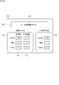
- FIGS. 5A and 5B are diagrams showing examples of support screens according to the first embodiment.
- the support screen 500 includes a target value input portion 510, a detected angle display portion 520, and a determination result display portion 530.
- FIG. 5A and 5B are diagrams showing examples of support screens according to the first embodiment.
- the support screen 500 includes a target value input portion 510, a detected angle display portion 520, and a determination result display portion 530.
- the target value input section 510 is an area for inputting target values for the installation angles (horizontal angle, depression angle, and roll angle) of the radar 100 .
- Target value input portion 510 includes a target value display portion 511 and an allowable range display portion 512 .
- the target value display portion 511 is an area for displaying the target value of the installation angle of the radar 100 .
- the target value display section 511 includes input boxes for horizontal angle, depression angle, and roll angle. The user can input target values for the horizontal angle, the depression angle, and the roll angle in each input box. The input target values for horizontal angle, depression angle, and roll angle are displayed in respective input boxes.
- the allowable range display portion 512 is an area for displaying the allowable range (setting range) in which the installation angle of the radar is allowed to deviate from the target value.
- the allowable range display portion 512 includes input boxes for the allowable ranges of the horizontal angle, depression angle, and roll angle. The user can enter the allowable range for each of the horizontal angle, depression angle, and roll angle in each input box. The permissible ranges for each of the input horizontal angle, depression angle, and roll angle are displayed in each input box.
- the input boxes for the target values of the horizontal angle, the depression angle, and the roll angle are arranged in order in the vertical direction.
- the input boxes for the allowable ranges for the horizontal angle, the depression angle, and the roll angle are arranged in order in the vertical direction. This prevents the user from confusing the input boxes for the target values of the horizontal angle, the depression angle, and the roll angle with the input boxes for the allowable ranges of the horizontal angle, the depression angle, and the roll angle. Since the input boxes for the target values of the horizontal angle, the depression angle, and the roll angle are arranged in a predetermined order, the user may confuse the input boxes for the target values among the horizontal angle, the depression angle, and the roll angle. Suppressed.
- the user may confuse the input boxes for the tolerance range among the horizontal angle, depression angle, and roll angle. Suppressed. Furthermore, in the target value display section 511 and the allowable range display section 512, since the input boxes for the horizontal angle, the depression angle, and the roll angle are arranged in the same order, the user can easily remember this arrangement order, and the horizontal angle , the depression angle, and the roll angle can be easily input and can be easily confirmed.
- the target value display section 511 and the allowable range display section 512 are arranged at positions adjacent to each other in the horizontal direction.
- the target value input box for the horizontal angle in the target value display portion 511 and the input box for the allowable range of horizontal angle in the allowable range display portion 512 are arranged at laterally adjacent positions.
- the input box for the target value of the depression angle in the target value display portion 511 and the input box for the allowable range of depression angle in the allowable range display portion 512 are arranged at laterally adjacent positions.
- the roll angle target value input box in the target value display portion 511 and the roll angle allowable range input box in the allowable range display portion 512 are arranged at laterally adjacent positions.
- the user inputs the target value and allowable range of the installation angle (horizontal angle, depression angle, and roll angle) of the radar 100 to the target value input unit 510 .
- the radar installation angle adjustment support device 400 receives the target value and allowable range of the installation angle of the radar 100 (step S102).
- the angle sensor 150 detects the horizontal angle, depression angle, and roll angle of the radar 100 and transmits angle data.
- the radar installation angle adjustment support device 400 receives angle data from the angle sensor 150 (step S103).
- the detected angle received is displayed in the detected angle display portion 520 on the support screen 500 .
- the detected angle display section 520 is an area for displaying the angles (horizontal angle, depression angle, and roll angle) detected by the angle sensor 150 provided in the installed radar 100 .
- the detection angle display section 520 includes display boxes for horizontal angle, depression angle, and roll angle. The horizontal angle, depression angle, and roll angle detected by the angle sensor 150 are displayed in respective display boxes.
- the display boxes for the detected angles of the horizontal angle, depression angle, and roll angle are arranged in order in the vertical direction.
- the arrangement order of the display boxes for the detected angles of the horizontal angle, the depression angle, and the roll angle it is possible to prevent the user from confusing the detected angles among the horizontal angle, the depression angle, and the roll angle.
- the target value input section 510 and the detected angle display section 520 are arranged at positions adjacent to each other in the horizontal direction.
- the horizontal angle target value and allowable range input boxes in the target value input section 510 and the horizontal angle detection box in the detection angle display section 520 are positioned horizontally adjacent to each other (that is, at the same height). ).
- the input boxes for the target value and allowable range of the depression angle in the target value input section 510 and the display box for the detection angle of the depression angle in the detection angle display section 520 are arranged at laterally adjacent positions.
- the input boxes for the target value and allowable range of the roll angle in the target value input section 510 and the display box for the detected roll angle in the detected angle display section 520 are arranged at laterally adjacent positions. This makes it easier for the user to compare the target values and allowable ranges of the horizontal angle, the depression angle, and the roll angle with the detected angles of the horizontal angle, the depression angle, and the roll angle.
- the processor 401 calculates the difference (angular difference) between the target values of the horizontal angle, the depression angle, and the roll angle given by the user and the detection values of the horizontal angle, the depression angle, and the roll angle detected by the angle sensor 150. Calculate (step S104).
- the processor 401 determines whether the angle differences calculated for each of the horizontal angle, depression angle, and roll angle are within the allowable range (step S105). If the angular difference in any one of the horizontal angle, the depression angle, and the roll angle exceeds the allowable range, that is, if the determination result is negative (NO in step S105), the processor 401 corrects the installation angle of the radar 100. (the angle based on the angle difference between the installation angle of the radar 100 and the target installation angle) is displayed on the determination result display section 530 of the support screen 500 (step S106).
- the determination result display unit 530 determines whether the difference (angle difference) between the target value displayed in the target value display unit 511 and the angle displayed in the detected angle display unit 520 is within the allowable range. This is an area for displaying the judgment result.
- the determination result display section 530 is arranged so as to be vertically aligned with the target value input section 510 and the detection angle display section 520 . In the example of FIGS. 5A and 5B, the determination result display section 530 is arranged above the target value input section 510 and the detected angle display section 520 . Note that the arrangement relationship of the target value input unit 510, the detection angle display unit 520, and the determination result display unit 530 is not limiting. It may be arranged below.
- the allowable range is an example of a predetermined setting range.
- the setting range does not have to be the range defined by the user.
- the setting range may be a range fixed in advance to the radar installation angle adjustment support device 400, or may be set from a server or an information terminal connected to the radar installation angle adjustment support device 400 via a communication network. It may be the transmitted range.
- FIG. 5A shows an example in which a negative determination result is displayed on the determination result display section 530.
- the correction information 531 is information generated based on the calculated angular difference.
- the correction information 531 includes a correction direction and correction amount for at least one of the horizontal angle, depression angle, and roll angle of the radar 100 .
- the target value of the horizontal angle is 130°
- the detected horizontal angle is 127°
- the angle difference is 3°. Since the horizontal angle tolerance is ⁇ 1°, the angle difference exceeds the tolerance.
- the target value of the depression angle is 5°
- the detected depression angle is 4°
- the angle difference is 1°.
- the correction information 531 includes text information "Insufficient adjustment” indicating that the angle adjustment has not been completed, and "Move the radar 3 degrees to the left and 1 degree downward” indicating the direction and amount of correction of the angle of the radar. °, please tilt 1.2° clockwise.” Such correction information is generated based on angular differences of 3°, 1°, and ⁇ 1.2° in horizontal, depression, and roll angles, respectively. A user can modify the installation angle of the radar 100 according to the modification information 531 .
- the processor 401 After displaying the correction information 531 on the determination result display unit 530, the processor 401 returns to step S103. Accordingly, each time angle data is received by the communication I/F 407, the angle difference between the target value and the detected angle is calculated for each of the horizontal angle, the depression angle, and the roll angle, and whether the angle difference is included in the allowable range is determined. is determined. If the determination result is negative, the correction information in the determination result display section 530 is updated.
- step S105 If all the angular differences of the horizontal angle, the depression angle, and the roll angle are within the permissible range, that is, if the determination result is affirmative (YES in step S105), the processor 401 determines that the angular difference is within the permissible range. is displayed on the determination result display section 530 of the support screen 500 (step S107).
- FIG. 5B shows an example in which a positive determination result is displayed on the determination result display section 530.
- Affirmative information 532 is information for notifying the user that the angle adjustment has been completed.
- the display color of the positive information 532 is different from the display color of the correction information 531 .
- the correction information 531 is displayed in red
- the positive information 532 is displayed in green. Since the display color of the affirmative information 532 is different from the display color of the correction information 531, the user can easily recognize that the display in the determination result display section 530 has changed from the correction information 531 to the affirmative information 532.
- the target value of the horizontal angle is 130°, whereas the detected horizontal angle is 129°, and the angle difference is 1°. Since the horizontal angle tolerance is ⁇ 1°, the angular difference is included in the tolerance. While the target value of the depression angle is 5°, the detected depression angle is 4°, and the angle difference is 1°. Since the allowable range of the depression angle is ⁇ 1°, the angle difference is included in the allowable range. While the target value of the roll angle is 0°, the detected roll angle is ⁇ 0.2°, and the angle difference is ⁇ 0.2°. Since the roll angle tolerance is ⁇ 1°, the angle difference is included in the tolerance.
- the affirmative information 532 includes "OK" text information indicating that the angle adjustment has been completed, and "within the allowable range” text information indicating that the angle difference is within the allowable range. By confirming the affirmative information 532, the user can recognize that the adjustment of the installation angle of the radar 100 has been completed.
- FIG. 6 is a perspective view showing an example of the external configuration of the radar 100 according to the second embodiment.
- the radar body 102 is equipped with not only an angle sensor 150 but also a GNSS (Global Navigation Satellite System) receiver 160 .
- GNSS receiver 160 is an example of a position sensor.
- the GNSS receiver 160 receives information transmitted from a plurality of satellites, and based on the received information, position information (hereinafter referred to as (referred to as “installation location information”). Since the configuration of the radar 100 according to the present embodiment is the same as that of the radar 100 according to the first embodiment, the same components are denoted by the same reference numerals, and description thereof is omitted.
- FIG. 7 is a block diagram showing an example of the configuration of the radar installation angle adjustment support device according to the second embodiment.
- the communication I/F 407 communicates not only with the angle sensor 150 but also with the GNSS receiver 160 .
- Communication I/F 407 can receive installation position information from GNSS receiver 160 . Since the configuration of the radar installation angle adjustment support device 400 according to the present embodiment is the same as the configuration of the radar installation angle adjustment support device 400 according to the first embodiment, the same components are denoted by the same reference numerals and explanations are given. omitted.
- FIG. 8 is a flow chart showing an example of the operation procedure of the radar installation angle adjustment support device 400 according to the second embodiment.
- the processor 401 starts the angle adjustment support program 409, the radar installation angle adjustment support device 400 performs operations as described below.
- the processor 401 causes the display device 405 to display a support screen for supporting adjustment of the installation angle of the radar 100 (step S201).
- the support screen 600 includes a target position information display portion 610, an installation height display portion 620, a radar angle information display portion 630, an installation position information display portion 640, and a determination result display. section 650;
- the target position information display unit 610 is an area for inputting target position information indicating the target value of the radio wave irradiation position of the radar 100 and displaying the input target position information.
- the radio wave irradiation position is the intersection of the radio wave irradiation axis of the radar 100 and the ground surface.
- the target position information is, for example, absolute position information and includes latitude and longitude.
- Target position information display section 610 includes input boxes for inputting latitude and longitude. The user can input the latitude and longitude of the target value of the radio wave irradiation position in each input box. The entered latitude and longitude are displayed in each input box.
- the installation height display section 620 is an area for inputting the installation height of the radar 100 and displaying the input installation height.
- the installation height of the radar 100 is the height of the installation position of the radar 100 from the ground surface.
- the installation height display portion 620 includes an input box for entering the installation height. The user can input the installation height in the input box. The entered installation height is displayed in the input box.
- the target position information display section 610 and the installation height display section 620 are arranged side by side in the vertical direction in the left area of the support screen 600 .
- An installation height display section 620 is arranged below the target position information display section 610 .
- the user inputs the target value (latitude and longitude) of the radio wave irradiation position of the radar 100 into the target position information display section 610 and inputs the installation height of the radar 100 into the installation height display section 620 .
- the radar installation angle adjustment support device 400 receives the target value of the radio wave irradiation position of the radar 100 (step S202), and receives the installation height (step S203).
- the GNSS receiver 160 acquires the installation position information of the radar 100 and transmits the installation position information.
- the installation position information includes latitude and longitude.
- the radar installation angle adjustment support device 400 receives installation position information from the GNSS receiver 160 (step S204).
- the received installation position information is displayed in installation position information display section 640 on support screen 500 .
- the installation position information display section 640 is an area for displaying the installation position information (latitude and longitude) of the radar 100 .
- the installation position information display section 640 includes latitude and longitude display boxes. The latitude and longitude obtained by the GNSS receiver 160 are displayed in each display box.
- the installation height display section 620 and the installation position information display section 640 are arranged side by side in the horizontal direction in the lower area of the support screen 600 .
- An installation position information display section 640 is arranged to the right of the installation height display section 620 .
- the processor 401 includes target values (latitude and longitude) of the radio wave irradiation position given by the user, installation position information (latitude and longitude) of the radar 100 given by the GNSS receiver 160, and radar 100 given by the user.
- the target values of the installation angles (horizontal angle, depression angle, and roll angle) of the radar 100 are determined (step S205). That is, the distance from the installation position of the radar 100 to the target radio wave irradiation position is determined based on the target value of the radio wave irradiation position and the installation position information of the radar 100 detected by the GNSS receiver 160 .
- a target value for the installation angle of radar 100 is determined based on the calculated distance and the installation height of radar 100 .
- the non-volatile memory 402 stores a correspondence table showing the correspondence between the distance from the installation position of the radar 100 to the target radio wave irradiation position, the installation height of the radar 100, and the target value of the installation angle of the radar 100.
- the processor 401 can refer to the correspondence table to determine the target value of the installation angle of the radar 100 .
- the processor 401 may calculate the target value of the installation angle of the radar 100 from the distance from the installation position of the radar 100 to the target radio wave irradiation position and the installation height of the radar 100 .
- the determined target value of the installation angle is displayed in the radar angle information display section 630 of the support screen 600 .
- the target position information display section 610 and the radar angle information display section 630 are arranged side by side in the horizontal direction in the vertical center area of the support screen 600 .
- a radar angle information display section 630 is arranged to the right of the target position information display section 610 .
- the radar angle information display section 630 and the installation position information display section 640 are displayed side by side in the vertical direction in the right area of the support screen 600 .
- a radar angle information display section 630 is arranged above the installation position information display section 640 .
- the radar angle information display section 630 includes a target value display section 631 and a detected angle display section 632.
- the target value display portion 631 is an area for displaying the target value of the installation angle of the radar 100 .
- the target value display section 631 includes display boxes for horizontal angle, depression angle, and roll angle. The determined target values for the horizontal angle, the depression angle, and the roll angle are displayed in respective display boxes.
- the display boxes for the target values of the horizontal angle, the depression angle, and the roll angle are arranged in order in the vertical direction. Since the display boxes for the target values of the horizontal angle, the angle of depression, and the roll angle are arranged in a predetermined order, the user may confuse the display boxes for the target values among the horizontal angle, the angle of depression, and the roll angle. Suppressed.
- the angle sensor 150 detects the horizontal angle, depression angle, and roll angle of the radar 100 and transmits angle data.
- the radar installation angle adjustment support device 400 receives angle data from the angle sensor 150 (step S206).
- the detected angle received is displayed in the detected angle display portion 632 on the support screen 600 .
- the detected angle display portion 632 is an area for displaying the angles (horizontal angle, depression angle, and roll angle) detected by the angle sensor 150 provided in the installed radar 100 .
- the detection angle display section 632 includes display boxes for horizontal angle, depression angle, and roll angle. The horizontal angle, depression angle, and roll angle detected by the angle sensor 150 are displayed in respective display boxes.
- the display boxes for the detected angles of the horizontal angle, depression angle, and roll angle are arranged in order in the vertical direction.
- the arrangement order of the display boxes for the detected angles of the horizontal angle, the depression angle, and the roll angle it is possible to prevent the user from confusing the detected angles among the horizontal angle, the depression angle, and the roll angle.
- the arrangement order of the display boxes for the detected angles of the horizontal angle, the angle of depression, and the roll angle in the detected angle display section 632, and the input boxes for the target values of the horizontal angle, the angle of depression, and the roll angle in the target value display section 631 Since the arrangement order is unified, the user can easily remember this arrangement order, and can easily check the target values and detected angles of the horizontal angle, the depression angle, and the roll angle.
- the target value display section 631 and the detection angle display section 632 are arranged at positions adjacent to each other in the horizontal direction.
- the display box for the target value of the horizontal angle in the target value display section 631 and the display box for the detected angle of the horizontal angle in the detection angle display section 632 are arranged at laterally adjacent positions (that is, at the same height). be.
- the display box for the target value of the depression angle in the target value display section 631 and the display box for the detection angle of the depression angle in the detected angle display section 632 are arranged at laterally adjacent positions.
- the display box for the target value of the roll angle in the target value display portion 631 and the display box for the detected roll angle in the detected angle display portion 632 are arranged at laterally adjacent positions. This makes it easier for the user to compare the target values of the horizontal angle, the depression angle, and the roll angle with the detected angles of the horizontal angle, the depression angle, and the roll angle.
- the processor 401 calculates the difference between the target values of the horizontal angle, the depression angle, and the roll angle given by the user and the detection values of the horizontal angle, the depression angle, and the roll angle detected by the angle sensor 150 (step S207).
- the processor 401 determines whether the angle differences calculated for each of the horizontal angle, depression angle, and roll angle are within the allowable range (step S208).
- the permissible range is not input by the user into the radar installation angle adjustment support device 400 but is pre-stored in the non-volatile memory 402 . If the angular difference in any one of the horizontal angle, depression angle, and roll angle exceeds the allowable range, that is, if the determination result is negative (NO in step S208), the processor 401 corrects the installation angle of the radar 100. is displayed on the determination result display section 650 in the support screen 600 (step S209).
- the determination result display unit 650 determines whether the difference (angle difference) between the target value displayed in the target value display unit 631 and the angle displayed in the detected angle display unit 632 is within the allowable range. This is an area for displaying the judgment result.
- the determination result display section 650 is arranged above the target position information display section 610 and the radar angle information display section 630 . Note that the positional relationship between the target position information display portion 610, the installation height display portion 620, the radar angle information display portion 630, the installation position information display portion 640, and the determination result display portion 650 on the support screen 600 is It is not limited to what has been described in the embodiment.
- FIG. 9A shows an example in which a negative determination result is displayed on the determination result display section 650.
- the correction information 651 is the same as the correction information 531 described in the first embodiment, so description thereof will be omitted.
- step S206 After displaying the correction information 651 on the determination result display unit 650, the processor 401 returns to step S206. Accordingly, each time angle data is received by the communication I/F 407, the angle difference between the target value and the detected angle is calculated for each of the horizontal angle, the depression angle, and the roll angle, and whether the angle difference is included in the allowable range is determined. is determined. If the determination result is negative, the correction information in the determination result display section 650 is updated.
- step S208 If all the angular differences of the horizontal angle, the depression angle, and the roll angle are within the permissible range, that is, if the determination result is affirmative (YES in step S208), the processor 401 determines that the angular difference is within the permissible range. is displayed on the determination result display section 650 of the support screen 600 (step S210).
- FIG. 9B shows an example in which a positive determination result is displayed on the determination result display section 530.
- the affirmative information 652 is the same as the affirmative information 652 described in the first embodiment, so description thereof will be omitted.
- the target value of the installation angle of the radar 100 is determined based on the target value of the radio wave irradiation position of the radar 100, the installation position of the radar 100, and the installation height of the radar 100, but this is not the only option. not.
- the target value of the installation angle of radar 100 may be determined based on the installation height of radar 100 . That is, the distance from the installation position of the radar 100 to the target radio wave irradiation position is set as a specified value, the installation height of the radar 100 is received by the radar installation angle adjustment support device 400 from the user or the server, and the given installation height is set. Based on this, the target value of the installation angle of the radar 100 may be determined.
- the non-volatile memory 402 stores a correspondence table indicating the correspondence between the installation height of the radar 100 and the target value of the installation angle of the radar 100, and the processor 401 refers to the correspondence table to A target value of the installation angle corresponding to the installation height of the can be specified.
- a radar installation angle adjustment support device 400 includes a display device 405 and a graphic controller 404 .
- the graphic controller 404 causes the display device 405 to display support screens 500 and 600 for supporting adjustment of the installation angle of the radar 100 .
- the support screens 500 and 600 include target value display portions 511 and 631, detection angle display portions 520 and 632, and determination result display portions 530 and 650, respectively.
- the target value display units 511 and 631 are configured to display the target value of the installation angle of the radar 100 .
- Detected angle display units 520 and 632 are configured to display the installation angle detected by angle sensor 150 that detects the installation angle of radar 100 .
- the determination result display units 530 and 650 are configured such that the angle difference between the target value displayed in the target value display units 511 and 631 and the angle displayed in the detected angle display units 520 and 632 is within an allowable range (predetermined set range). is configured to display the determination result of determining whether or not it is included in the
- the graphic controller 404 displays the correction information 531, 651 (angle based on the angular difference) on the determination result display sections 530, 650 when the angular difference is out of the allowable range.
- Correction information 531 and 651 is information for correcting the installation angle of radar 100 .
- the user can adjust the installation angle of the radar 100 by confirming the correction information 531 and 651 on the support screens 500 and 600 . Therefore, it is possible to assist the user in adjusting the installation angle of the radar 100 .
- the installation angle of the radar 100 may include at least one of the horizontal angle, depression angle, and roll angle of the radar 100 .
- the graphic controller 404 may display at least one of the horizontal angle, depression angle, and roll angle of the radar 100 on the detection angle display units 520 and 632 . This can assist adjustment of at least one of the horizontal angle, depression angle, and roll angle of the radar 100 .
- the correction information 531, 651 may include an angle for correcting at least one of the horizontal angle, depression angle, and roll angle of the radar 100.
- the graphics controller 404 may cause the support screens 500 and 600 to display an angle for correcting at least one of the horizontal angle, depression angle, and roll angle of the radar 100 . Accordingly, the user can appropriately correct at least one of the horizontal angle, depression angle, and roll angle of the radar 100 by checking the correction information.
- the radar installation angle adjustment support device 400 may further include a communication I/F (receiving unit) 407 .
- Communication I/F 407 is configured to receive angle data indicating the angle detected by angle sensor 150 .
- the graphic controller 404 updates the display of the correction information 531 and 651 each time angle data is received by the communication I/F 407, and when the angle difference changes to be within the allowable range, the determination result display unit 530, The display of 650 may be switched from the correction information 531,651 to the positive information 532,652.
- Affirmative information 532 and 652 is information indicating that the angular difference is within the allowable range.
- the user can easily correct the installation angle of the radar 100 according to the support screens 500 and 600 until the display in the determination result display units 530 and 650 switches from the correction information 531 and 651 to the positive information 532 and 652. Moreover, the installation angle can be appropriately adjusted.
- the display color for displaying the correction information 531, 651 and the display color for displaying the affirmative information 532, 652 may be different from each other. Thereby, the user can easily confirm the switching from the correction information 531, 651 to the positive information 532, 652 in the determination result display portions 530, 650.
- the support screen 600 may further include an installation height display section 620.
- the installation height display section 620 is configured to display the installation height of the radar 100 .
- the graphic controller 404 may cause the target value display sections 511 and 631 to display the target value of the installation angle calculated based on the installation height displayed on the installation height display section 620 . This makes it possible to present the user with an appropriate target value for the installation angle according to the installation height of the radar 100 .
- the support screen 600 may further include an installation position information display section 640 and a target position information display section 610.
- the installation position information display unit 640 is configured to display installation position information indicating the installation position of the radar 100 .
- the target position information display unit 610 is configured to display target position information indicating the target value of the radio wave irradiation position of the radar 100 .
- the graphic controller 404 Based on the installation position information displayed in the installation position information display section 640, the target position information displayed in the target position information display section 610, and the installation height displayed in the installation height display section 620, the graphic controller 404 The calculated target value of the installation angle may be displayed on the target value display units 511 and 631 . Accordingly, it is possible to present to the user the installation position of the radar 100 , the target value of the radio wave irradiation position of the radar 100 , and the appropriate target value of the installation angle according to the installation height of the radar 100 .
- the graphic controller 404 may cause the installation position information display section 640 to display installation position information indicating the position detected by the GNSS receiver 160 that detects the position of the radar 100 . Thereby, the target value of the installation angle of the radar 100 can be calculated using the accurate installation position information of the radar 100 detected by the GNSS receiver 160 .
- REFERENCE SIGNS LIST 100 radar 101 transmission/reception surface 102 radar main body 103 depression angle adjustment unit 103a arm 103b coupling unit 104 horizontal angle adjustment unit 105 roll angle adjustment unit 105a lower member 105b upper member 150 angle sensor 160 GNSS receiver 200 arm 300 target area 400 radar installation angle adjustment Support device 401 Processor 402 Nonvolatile memory 403 Volatile memory 404 Graphic controller 405 Display device 406 Input device 409 Angle adjustment support program 500, 600 Support screen 510 Target value input unit 511, 631 Target value display unit 512 Allowable range display unit 520, 632 Detection angle display section 530, 650 Determination result display section 531, 651 Correction information 532, 652 Affirmative information 610 Target position information display section 620 Installation height display section 630 Radar angle information display section 640 Installation position information display section V Vehicle
Landscapes
- Engineering & Computer Science (AREA)
- Radar, Positioning & Navigation (AREA)
- Remote Sensing (AREA)
- Physics & Mathematics (AREA)
- General Physics & Mathematics (AREA)
- Computer Networks & Wireless Communication (AREA)
- Electromagnetism (AREA)
- Radar Systems Or Details Thereof (AREA)
Priority Applications (3)
| Application Number | Priority Date | Filing Date | Title |
|---|---|---|---|
| JP2022579343A JP7848695B2 (ja) | 2021-02-03 | 2021-11-10 | レーダ設置角度調整支援装置及びコンピュータプログラム |
| CN202180077652.3A CN116457852A (zh) | 2021-02-03 | 2021-11-10 | 雷达设置角度调整辅助装置和计算机程序 |
| US18/273,547 US20240094342A1 (en) | 2021-02-03 | 2021-11-10 | Radar installation angle adjustment assistance device and computer program |
Applications Claiming Priority (2)
| Application Number | Priority Date | Filing Date | Title |
|---|---|---|---|
| JP2021-015579 | 2021-02-03 | ||
| JP2021015579 | 2021-02-03 |
Publications (1)
| Publication Number | Publication Date |
|---|---|
| WO2022168387A1 true WO2022168387A1 (ja) | 2022-08-11 |
Family
ID=82741036
Family Applications (1)
| Application Number | Title | Priority Date | Filing Date |
|---|---|---|---|
| PCT/JP2021/041375 Ceased WO2022168387A1 (ja) | 2021-02-03 | 2021-11-10 | レーダ設置角度調整支援装置及びコンピュータプログラム |
Country Status (4)
| Country | Link |
|---|---|
| US (1) | US20240094342A1 (https=) |
| JP (1) | JP7848695B2 (https=) |
| CN (1) | CN116457852A (https=) |
| WO (1) | WO2022168387A1 (https=) |
Cited By (4)
| Publication number | Priority date | Publication date | Assignee | Title |
|---|---|---|---|---|
| US20250060479A1 (en) * | 2022-01-13 | 2025-02-20 | Sumitomo Electric Industries, Ltd. | Radio-wave sensor installation assistance device, computer program, and radio-wave sensor installation position determination method |
| US20250078653A1 (en) * | 2022-01-13 | 2025-03-06 | Sumitomo Electric Industries, Ltd. | Installation support device for radio wave sensor, computer program, method of determining installation position of radio wave sensor, and method of supporting installation of radio wave sensor |
| EP4560351A1 (en) * | 2023-11-23 | 2025-05-28 | Smart Radar System, Inc. | Radar device used in speed camera |
| WO2025164125A1 (ja) * | 2024-01-30 | 2025-08-07 | Astemo株式会社 | 移動体監視装置 |
Citations (4)
| Publication number | Priority date | Publication date | Assignee | Title |
|---|---|---|---|---|
| JP2005172824A (ja) * | 2004-12-06 | 2005-06-30 | Fujitsu Ten Ltd | 車両用レーダ装置の取付け角度調整方法 |
| JP2011058817A (ja) * | 2009-09-07 | 2011-03-24 | Fujitsu Ten Ltd | レーダ装置、および、アンテナ角度調整方法 |
| JP2013061168A (ja) * | 2011-09-12 | 2013-04-04 | Denso Wave Inc | レーザレーダ装置の設置角度設定システム及びレーザレーダ装置の設置角度設定方法 |
| US20160299217A1 (en) * | 2015-04-13 | 2016-10-13 | Mando Corporation | Installation angle distinction apparatus and distinction method thereof |
Family Cites Families (13)
| Publication number | Priority date | Publication date | Assignee | Title |
|---|---|---|---|---|
| JPH10132920A (ja) * | 1996-11-01 | 1998-05-22 | Honda Access Corp | 車載用レーダ装置 |
| JP3462740B2 (ja) * | 1998-01-06 | 2003-11-05 | 株式会社日立製作所 | 車載レーダの軸調整方法 |
| US6556166B1 (en) * | 2002-02-19 | 2003-04-29 | Delphi Technologies, Inc. | Method of measuring elevational mis-alignment of an automotive radar sensor |
| JP4356573B2 (ja) | 2004-09-24 | 2009-11-04 | 株式会社日立製作所 | レーダの設置情報の確認画面と調整画面の表示方法 |
| JP2007013814A (ja) | 2005-07-01 | 2007-01-18 | Secom Co Ltd | 検出領域の設定装置 |
| CN102064386B (zh) * | 2010-07-31 | 2014-08-20 | 华为技术有限公司 | 一种用于调整天线角度的方法及辅助装置 |
| CN106662638B (zh) * | 2014-08-15 | 2019-06-25 | 罗伯特·博世有限公司 | 汽车雷达对准 |
| CN109581306B (zh) * | 2018-11-21 | 2020-12-08 | 浙江大华技术股份有限公司 | 一种雷球校准系统及方法 |
| CN110988801A (zh) * | 2019-10-25 | 2020-04-10 | 东软睿驰汽车技术(沈阳)有限公司 | 一种雷达的安装角度调整方法和装置 |
| CN110954882A (zh) * | 2019-12-30 | 2020-04-03 | 苏州安智汽车零部件有限公司 | 雷达安装校准装置及其校准方法 |
| EP4143599B1 (en) * | 2020-04-30 | 2025-08-06 | Teledyne FLIR Commercial Systems, Inc. | Installation and calibration of radar systems |
| CN118379698B (zh) | 2024-04-10 | 2025-02-07 | 北京大唐高鸿数据网络技术有限公司 | 一种数据集构建方法、装置、设备、程序产品及介质 |
| CN120412284B (zh) | 2025-06-30 | 2025-09-19 | 重庆长安汽车股份有限公司 | 车路协同标定系统、方法、电子设备及车辆 |
-
2021
- 2021-11-10 JP JP2022579343A patent/JP7848695B2/ja active Active
- 2021-11-10 WO PCT/JP2021/041375 patent/WO2022168387A1/ja not_active Ceased
- 2021-11-10 CN CN202180077652.3A patent/CN116457852A/zh active Pending
- 2021-11-10 US US18/273,547 patent/US20240094342A1/en active Pending
Patent Citations (4)
| Publication number | Priority date | Publication date | Assignee | Title |
|---|---|---|---|---|
| JP2005172824A (ja) * | 2004-12-06 | 2005-06-30 | Fujitsu Ten Ltd | 車両用レーダ装置の取付け角度調整方法 |
| JP2011058817A (ja) * | 2009-09-07 | 2011-03-24 | Fujitsu Ten Ltd | レーダ装置、および、アンテナ角度調整方法 |
| JP2013061168A (ja) * | 2011-09-12 | 2013-04-04 | Denso Wave Inc | レーザレーダ装置の設置角度設定システム及びレーザレーダ装置の設置角度設定方法 |
| US20160299217A1 (en) * | 2015-04-13 | 2016-10-13 | Mando Corporation | Installation angle distinction apparatus and distinction method thereof |
Cited By (6)
| Publication number | Priority date | Publication date | Assignee | Title |
|---|---|---|---|---|
| US20250060479A1 (en) * | 2022-01-13 | 2025-02-20 | Sumitomo Electric Industries, Ltd. | Radio-wave sensor installation assistance device, computer program, and radio-wave sensor installation position determination method |
| US20250078653A1 (en) * | 2022-01-13 | 2025-03-06 | Sumitomo Electric Industries, Ltd. | Installation support device for radio wave sensor, computer program, method of determining installation position of radio wave sensor, and method of supporting installation of radio wave sensor |
| US12597341B2 (en) * | 2022-01-13 | 2026-04-07 | Sumitomo Electric Industries, Ltd. | Installation support device for radio wave sensor, computer program, method of determining installation position of radio wave sensor, and method of supporting installation of radio wave sensor |
| US12601836B2 (en) * | 2022-01-13 | 2026-04-14 | Sumitomo Electric Industries, Ltd. | Radio-wave sensor installation assistance device, computer program, and radio-wave sensor installation position determination method |
| EP4560351A1 (en) * | 2023-11-23 | 2025-05-28 | Smart Radar System, Inc. | Radar device used in speed camera |
| WO2025164125A1 (ja) * | 2024-01-30 | 2025-08-07 | Astemo株式会社 | 移動体監視装置 |
Also Published As
| Publication number | Publication date |
|---|---|
| JPWO2022168387A1 (https=) | 2022-08-11 |
| US20240094342A1 (en) | 2024-03-21 |
| CN116457852A (zh) | 2023-07-18 |
| JP7848695B2 (ja) | 2026-04-21 |
Similar Documents
| Publication | Publication Date | Title |
|---|---|---|
| WO2022168387A1 (ja) | レーダ設置角度調整支援装置及びコンピュータプログラム | |
| US8941649B2 (en) | Augmented reality direction orientation mask | |
| JP2019157409A (ja) | 作業車両用旋回制御システム及び作業車両用警報制御システム | |
| US11134138B2 (en) | Mapless user interfaces for limited network conditions | |
| KR20210099124A (ko) | 포즈 데이터에 기초한 포지셔닝 방법 및 장치 | |
| KR102539287B1 (ko) | 라이다 센서의 신뢰성에 따른 차량 제어 장치 및 방법 | |
| US8134491B1 (en) | Systems and methods for terrain and obstacle detection by weather radar | |
| JPWO2022168387A5 (https=) | ||
| JP5625463B2 (ja) | 画像表示装置、画像表示システム及び照度特定方法 | |
| JP2016057066A (ja) | 判定装置、走行レーン判定方法、及び、走行レーン判定プログラム | |
| JP2020144226A (ja) | 地図更新システム、地図更新方法および地図更新プログラム | |
| JP2013108830A (ja) | 天候情報処理システム、天候情報処理サーバ、情報処理装置 | |
| KR20170016203A (ko) | 경로 안내 장치 및 그 제어 방법 | |
| JPH09179489A (ja) | 鳥瞰図表示ナビゲーション装置 | |
| JPWO2009104254A1 (ja) | 位置認識装置、補正方法、及び補正プログラム | |
| WO2021134099A1 (en) | Self-calibrating infrastructure sensor | |
| JP7452350B2 (ja) | 交通用検知装置および交通用検知方法 | |
| JP3438487B2 (ja) | 携帯型ナビゲーション装置 | |
| CN117269939A (zh) | 用于传感器的参数标定系统、方法及存储介质 | |
| AU2013350713B2 (en) | Map display device and map display system | |
| JP4631459B2 (ja) | 地図表示制御装置および地図表示制御制御プログラム。 | |
| JP4007924B2 (ja) | 携帯ナビゲーション装置 | |
| JP2005208337A (ja) | 地図表示装置 | |
| US20250310471A1 (en) | Control method, control system, and non-transitory computer-readable storage medium storing information processing program | |
| JP6451352B2 (ja) | 位置検出システム及び車載情報処理装置 |
Legal Events
| Date | Code | Title | Description |
|---|---|---|---|
| 121 | Ep: the epo has been informed by wipo that ep was designated in this application |
Ref document number: 21924774 Country of ref document: EP Kind code of ref document: A1 |
|
| WWE | Wipo information: entry into national phase |
Ref document number: 202180077652.3 Country of ref document: CN |
|
| ENP | Entry into the national phase |
Ref document number: 2022579343 Country of ref document: JP Kind code of ref document: A |
|
| WWE | Wipo information: entry into national phase |
Ref document number: 18273547 Country of ref document: US |
|
| NENP | Non-entry into the national phase |
Ref country code: DE |
|
| 122 | Ep: pct application non-entry in european phase |
Ref document number: 21924774 Country of ref document: EP Kind code of ref document: A1 |