WO2022163471A1 - スリップ状態検出装置およびサスペンション制御装置 - Google Patents
スリップ状態検出装置およびサスペンション制御装置 Download PDFInfo
- Publication number
- WO2022163471A1 WO2022163471A1 PCT/JP2022/001879 JP2022001879W WO2022163471A1 WO 2022163471 A1 WO2022163471 A1 WO 2022163471A1 JP 2022001879 W JP2022001879 W JP 2022001879W WO 2022163471 A1 WO2022163471 A1 WO 2022163471A1
- Authority
- WO
- WIPO (PCT)
- Prior art keywords
- slip ratio
- wheel
- wheel speed
- vehicle
- slip
- Prior art date
- Legal status (The legal status is an assumption and is not a legal conclusion. Google has not performed a legal analysis and makes no representation as to the accuracy of the status listed.)
- Ceased
Links
Images



Classifications
-
- B—PERFORMING OPERATIONS; TRANSPORTING
- B60—VEHICLES IN GENERAL
- B60G—VEHICLE SUSPENSION ARRANGEMENTS
- B60G17/00—Resilient suspensions having means for adjusting the spring or vibration-damper characteristics, for regulating the distance between a supporting surface and a sprung part of vehicle or for locking suspension during use to meet varying vehicular or surface conditions, e.g. due to speed or load
- B60G17/015—Resilient suspensions having means for adjusting the spring or vibration-damper characteristics, for regulating the distance between a supporting surface and a sprung part of vehicle or for locking suspension during use to meet varying vehicular or surface conditions, e.g. due to speed or load the regulating means comprising electric or electronic elements
- B60G17/016—Resilient suspensions having means for adjusting the spring or vibration-damper characteristics, for regulating the distance between a supporting surface and a sprung part of vehicle or for locking suspension during use to meet varying vehicular or surface conditions, e.g. due to speed or load the regulating means comprising electric or electronic elements characterised by their responsiveness, when the vehicle is travelling, to specific motion, a specific condition, or driver input
-
- B—PERFORMING OPERATIONS; TRANSPORTING
- B60—VEHICLES IN GENERAL
- B60G—VEHICLE SUSPENSION ARRANGEMENTS
- B60G17/00—Resilient suspensions having means for adjusting the spring or vibration-damper characteristics, for regulating the distance between a supporting surface and a sprung part of vehicle or for locking suspension during use to meet varying vehicular or surface conditions, e.g. due to speed or load
- B60G17/015—Resilient suspensions having means for adjusting the spring or vibration-damper characteristics, for regulating the distance between a supporting surface and a sprung part of vehicle or for locking suspension during use to meet varying vehicular or surface conditions, e.g. due to speed or load the regulating means comprising electric or electronic elements
- B60G17/018—Resilient suspensions having means for adjusting the spring or vibration-damper characteristics, for regulating the distance between a supporting surface and a sprung part of vehicle or for locking suspension during use to meet varying vehicular or surface conditions, e.g. due to speed or load the regulating means comprising electric or electronic elements characterised by the use of a specific signal treatment or control method
- B60G17/0182—Resilient suspensions having means for adjusting the spring or vibration-damper characteristics, for regulating the distance between a supporting surface and a sprung part of vehicle or for locking suspension during use to meet varying vehicular or surface conditions, e.g. due to speed or load the regulating means comprising electric or electronic elements characterised by the use of a specific signal treatment or control method involving parameter estimation, e.g. observer, Kalman filter
-
- B—PERFORMING OPERATIONS; TRANSPORTING
- B60—VEHICLES IN GENERAL
- B60G—VEHICLE SUSPENSION ARRANGEMENTS
- B60G17/00—Resilient suspensions having means for adjusting the spring or vibration-damper characteristics, for regulating the distance between a supporting surface and a sprung part of vehicle or for locking suspension during use to meet varying vehicular or surface conditions, e.g. due to speed or load
- B60G17/015—Resilient suspensions having means for adjusting the spring or vibration-damper characteristics, for regulating the distance between a supporting surface and a sprung part of vehicle or for locking suspension during use to meet varying vehicular or surface conditions, e.g. due to speed or load the regulating means comprising electric or electronic elements
-
- B—PERFORMING OPERATIONS; TRANSPORTING
- B60—VEHICLES IN GENERAL
- B60W—CONJOINT CONTROL OF VEHICLE SUB-UNITS OF DIFFERENT TYPE OR DIFFERENT FUNCTION; CONTROL SYSTEMS SPECIALLY ADAPTED FOR HYBRID VEHICLES; ROAD VEHICLE DRIVE CONTROL SYSTEMS FOR PURPOSES NOT RELATED TO THE CONTROL OF A PARTICULAR SUB-UNIT
- B60W10/00—Conjoint control of vehicle sub-units of different type or different function
- B60W10/22—Conjoint control of vehicle sub-units of different type or different function including control of suspension systems
-
- B—PERFORMING OPERATIONS; TRANSPORTING
- B60—VEHICLES IN GENERAL
- B60W—CONJOINT CONTROL OF VEHICLE SUB-UNITS OF DIFFERENT TYPE OR DIFFERENT FUNCTION; CONTROL SYSTEMS SPECIALLY ADAPTED FOR HYBRID VEHICLES; ROAD VEHICLE DRIVE CONTROL SYSTEMS FOR PURPOSES NOT RELATED TO THE CONTROL OF A PARTICULAR SUB-UNIT
- B60W40/00—Estimation or calculation of non-directly measurable driving parameters for road vehicle drive control systems not related to the control of a particular sub unit, e.g. by using mathematical models
- B60W40/10—Estimation or calculation of non-directly measurable driving parameters for road vehicle drive control systems not related to the control of a particular sub unit, e.g. by using mathematical models related to vehicle motion
-
- B—PERFORMING OPERATIONS; TRANSPORTING
- B60—VEHICLES IN GENERAL
- B60G—VEHICLE SUSPENSION ARRANGEMENTS
- B60G2400/00—Indexing codes relating to detected, measured or calculated conditions or factors
- B60G2400/05—Attitude
- B60G2400/052—Angular rate
- B60G2400/0523—Yaw rate
-
- B—PERFORMING OPERATIONS; TRANSPORTING
- B60—VEHICLES IN GENERAL
- B60G—VEHICLE SUSPENSION ARRANGEMENTS
- B60G2400/00—Indexing codes relating to detected, measured or calculated conditions or factors
- B60G2400/10—Acceleration; Deceleration
- B60G2400/104—Acceleration; Deceleration lateral or transversal with regard to vehicle
-
- B—PERFORMING OPERATIONS; TRANSPORTING
- B60—VEHICLES IN GENERAL
- B60G—VEHICLE SUSPENSION ARRANGEMENTS
- B60G2400/00—Indexing codes relating to detected, measured or calculated conditions or factors
- B60G2400/10—Acceleration; Deceleration
- B60G2400/106—Acceleration; Deceleration longitudinal with regard to vehicle, e.g. braking
-
- B—PERFORMING OPERATIONS; TRANSPORTING
- B60—VEHICLES IN GENERAL
- B60G—VEHICLE SUSPENSION ARRANGEMENTS
- B60G2400/00—Indexing codes relating to detected, measured or calculated conditions or factors
- B60G2400/20—Speed
- B60G2400/208—Speed of wheel rotation
-
- B—PERFORMING OPERATIONS; TRANSPORTING
- B60—VEHICLES IN GENERAL
- B60G—VEHICLE SUSPENSION ARRANGEMENTS
- B60G2400/00—Indexing codes relating to detected, measured or calculated conditions or factors
- B60G2400/25—Stroke; Height; Displacement
- B60G2400/252—Stroke; Height; Displacement vertical
-
- B—PERFORMING OPERATIONS; TRANSPORTING
- B60—VEHICLES IN GENERAL
- B60G—VEHICLE SUSPENSION ARRANGEMENTS
- B60G2400/00—Indexing codes relating to detected, measured or calculated conditions or factors
- B60G2400/30—Propulsion unit conditions
- B60G2400/39—Brake pedal position
-
- B—PERFORMING OPERATIONS; TRANSPORTING
- B60—VEHICLES IN GENERAL
- B60G—VEHICLE SUSPENSION ARRANGEMENTS
- B60G2400/00—Indexing codes relating to detected, measured or calculated conditions or factors
- B60G2400/40—Steering conditions
- B60G2400/41—Steering angle
-
- B—PERFORMING OPERATIONS; TRANSPORTING
- B60—VEHICLES IN GENERAL
- B60G—VEHICLE SUSPENSION ARRANGEMENTS
- B60G2400/00—Indexing codes relating to detected, measured or calculated conditions or factors
- B60G2400/90—Other conditions or factors
-
- B—PERFORMING OPERATIONS; TRANSPORTING
- B60—VEHICLES IN GENERAL
- B60G—VEHICLE SUSPENSION ARRANGEMENTS
- B60G2500/00—Indexing codes relating to the regulated action or device
- B60G2500/20—Spring action or springs
-
- B—PERFORMING OPERATIONS; TRANSPORTING
- B60—VEHICLES IN GENERAL
- B60G—VEHICLE SUSPENSION ARRANGEMENTS
- B60G2800/00—Indexing codes relating to the type of movement or to the condition of the vehicle and to the end result to be achieved by the control action
- B60G2800/21—Traction, slip, skid or slide control
-
- B—PERFORMING OPERATIONS; TRANSPORTING
- B60—VEHICLES IN GENERAL
- B60W—CONJOINT CONTROL OF VEHICLE SUB-UNITS OF DIFFERENT TYPE OR DIFFERENT FUNCTION; CONTROL SYSTEMS SPECIALLY ADAPTED FOR HYBRID VEHICLES; ROAD VEHICLE DRIVE CONTROL SYSTEMS FOR PURPOSES NOT RELATED TO THE CONTROL OF A PARTICULAR SUB-UNIT
- B60W2520/00—Input parameters relating to overall vehicle dynamics
- B60W2520/10—Longitudinal speed
- B60W2520/105—Longitudinal acceleration
-
- B—PERFORMING OPERATIONS; TRANSPORTING
- B60—VEHICLES IN GENERAL
- B60W—CONJOINT CONTROL OF VEHICLE SUB-UNITS OF DIFFERENT TYPE OR DIFFERENT FUNCTION; CONTROL SYSTEMS SPECIALLY ADAPTED FOR HYBRID VEHICLES; ROAD VEHICLE DRIVE CONTROL SYSTEMS FOR PURPOSES NOT RELATED TO THE CONTROL OF A PARTICULAR SUB-UNIT
- B60W2520/00—Input parameters relating to overall vehicle dynamics
- B60W2520/26—Wheel slip
-
- B—PERFORMING OPERATIONS; TRANSPORTING
- B60—VEHICLES IN GENERAL
- B60W—CONJOINT CONTROL OF VEHICLE SUB-UNITS OF DIFFERENT TYPE OR DIFFERENT FUNCTION; CONTROL SYSTEMS SPECIALLY ADAPTED FOR HYBRID VEHICLES; ROAD VEHICLE DRIVE CONTROL SYSTEMS FOR PURPOSES NOT RELATED TO THE CONTROL OF A PARTICULAR SUB-UNIT
- B60W2520/00—Input parameters relating to overall vehicle dynamics
- B60W2520/28—Wheel speed
-
- B—PERFORMING OPERATIONS; TRANSPORTING
- B60—VEHICLES IN GENERAL
- B60W—CONJOINT CONTROL OF VEHICLE SUB-UNITS OF DIFFERENT TYPE OR DIFFERENT FUNCTION; CONTROL SYSTEMS SPECIALLY ADAPTED FOR HYBRID VEHICLES; ROAD VEHICLE DRIVE CONTROL SYSTEMS FOR PURPOSES NOT RELATED TO THE CONTROL OF A PARTICULAR SUB-UNIT
- B60W2530/00—Input parameters relating to vehicle conditions or values, not covered by groups B60W2510/00 or B60W2520/00
- B60W2530/20—Tyre data
-
- B—PERFORMING OPERATIONS; TRANSPORTING
- B60—VEHICLES IN GENERAL
- B60Y—INDEXING SCHEME RELATING TO ASPECTS CROSS-CUTTING VEHICLE TECHNOLOGY
- B60Y2400/00—Special features of vehicle units
- B60Y2400/86—Suspension systems
Definitions
- the present disclosure relates to, for example, a slip state detection device and a suspension control device mounted on a vehicle such as an automobile.
- Patent Document 1 describes a tire condition determination device that detects the acceleration/deceleration of the vehicle body and the rotation speed of the wheels, and determines the tire condition in consideration of the tire torsion spring element and the front and rear suspension spring element.
- Patent Literature 2 describes a suspension control device that obtains the slip ratio change amount of a wheel and corrects the gain of the wheel speed fluctuation amount.
- An object of one embodiment of the present invention is to provide a slip state detection device and a suspension control device that can improve the slip ratio and, by extension, the accuracy of estimating the vertical state of the vehicle body.
- An embodiment of the present invention is a slip condition detection device comprising: a tire characteristic-considered slip ratio determiner that determines a tire characteristic-considered slip ratio according to a longitudinal acceleration of a vehicle detected by a longitudinal acceleration detector and a tire characteristic; and a corrected slip ratio determination unit for correcting the tire characteristic-considered slip ratio with the slip ratio of each wheel obtained according to the rotational speed signal of each wheel to determine the corrected slip ratio of each wheel.
- one embodiment of the present invention is a suspension control device that detects longitudinal acceleration of a vehicle and outputs a longitudinal acceleration signal.
- a wheel rotation speed detection unit that outputs a rotation speed signal of , and the longitudinal acceleration signal and the rotation speed signal of each wheel are input, and a slip ratio considering tire characteristics is obtained from the input longitudinal acceleration signal and tire characteristics.
- FIG. 1 is an overall configuration diagram showing a four-wheel vehicle equipped with a slip state detection device and a suspension control device according to an embodiment
- FIG. 2 is a block diagram showing a controller (ECU), a damping force variable shock absorber (control damper), etc. in FIG. 1
- FIG. 3 is a block diagram showing a vehicle state estimation unit in FIG. 2
- FIG. 4 is a block diagram showing a vehicle vertical state estimation unit in FIG. 3
- FIG. 5 is a block diagram showing a wheel speed estimator in FIG. 4
- FIG. 6 is a block diagram showing a second wheel speed calculator in FIG. 5
- FIG. 7 is a block diagram showing a slip ratio calculator in FIG. 6
- FIG. 7 is a block diagram showing a slip ratio replacement coefficient calculator in FIG. 6
- FIG. 6 is a block diagram showing a slip ratio replacement coefficient calculator in FIG. 6
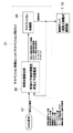
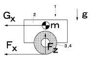
- FIG. 3 is an explanatory diagram showing the sum of tire longitudinal forces Fx, the sum of tire vertical forces Fz, vehicle body longitudinal acceleration (corrected longitudinal acceleration Gxf), vehicle weight m, and gravitational acceleration g.
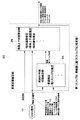
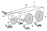
- FIG. 4 is an explanatory diagram showing wheel speeds VwFL, VwFR, VwRL, and VwRR of respective wheels and vehicle longitudinal speed VBx;
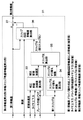
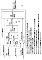
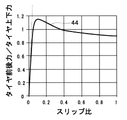
- FIG. 4 is a characteristic diagram showing an example of the relationship between the "slip ratio” and the "longitudinal force of tire/vertical force of tire”;
- a total of four wheels 3 and 4 for example, left and right front wheels 3 and left and right rear wheels 4 (only one is shown), are provided below a vehicle body 2 that constitutes the body of a vehicle 1, which is an automobile. It is Between the left and right front wheels 3 and the vehicle body 2, front wheel suspensions 5, 5 (hereinafter referred to as front wheel suspensions 5) are interposed.
- the front wheel suspension 5 includes a suspension spring 6 (hereinafter referred to as the spring 6) and a damping force adjustable damper 7 (hereinafter referred to as the damper 7) provided in parallel with the spring 6.
- the rear wheel suspension 8 includes a suspension spring 9 (hereinafter referred to as the spring 9) and a damping force adjustable shock absorber 10 (hereinafter referred to as the shock absorber 10) provided in parallel with the spring 9.
- the dampers 7 and 10 are composed of, for example, semi-active dampers that are hydraulic cylinder devices (damping force variable shock absorbers) capable of adjusting the damping force. That is, the vehicle 1 is equipped with a semi-active suspension system using a damping force variable shock absorber.
- the dampers 7 and 10 are damping force variable type dampers provided between the vehicle body 2 and the wheels 3 and 4 (more specifically, the wheel-side members that support the wheels 3 and 4). It is a damping force generator (damping force variable shock absorber).
- the shock absorbers 7 and 10 correspond to a vehicle body attitude control device that controls the attitude of the vehicle 1 . That is, the shock absorbers 7 and 10 are variably controlled in the characteristics of the generated damping force (damping force characteristics) by the suspension control unit 21, which will be described later. For this reason, the shock absorbers 7 and 10 are provided with damping force adjustment valves and solenoids in order to continuously (or in multiple steps) adjust the damping force characteristics from hard characteristics (hard characteristics) to soft characteristics (soft characteristics).
- a damping force adjustment actuator (not shown) consisting of, for example, is attached.
- the damping force characteristics of the dampers 7 and 10 are variably adjusted according to a command current (control signal, control command) supplied from the suspension control unit 21 to the damping force adjusting actuator.
- the damping force adjustment valve conventionally known structures such as a pressure control method for controlling the pilot pressure of the damping force generating valve and a flow rate control method for controlling the passage area can be used.
- the dampers 7 and 10 only need to be able to adjust the damping force continuously (or in multiple stages), and may be, for example, a pneumatic damper, an electromagnetic damper, an electrorheological fluid damper, or a magnetic fluid damper.
- the dampers 7 and 10 include an air damper (air suspension) using an air spring (air spring), a hydraulic damper (vehicle height adjustment device) in which front, rear, left, and right hydraulic cylinders are connected by piping, and a It may be a stabilizer or the like that gives force.
- the dampers 7, 10 may be full active dampers composed of hydraulic, electric or pneumatic actuators capable of generating thrust. That is, the vehicle 1 may be equipped with a full active suspension system using a full active damper.
- the vehicle 1 is provided with a longitudinal acceleration sensor 11, a lateral acceleration sensor 12, a wheel speed sensor 13, a steering angle sensor 14, a yaw rate sensor 15, and a brake switch 16.
- These sensors 11 , 12 , 13 , 14 , 15 and switch 16 are sensors and switches generally mounted on vehicle 1 , more specifically, are mainly used for braking, driving, and steering control of vehicle 1 . are the sensors and switches that are
- a longitudinal acceleration sensor 11 as longitudinal acceleration detection means is provided, for example, on the vehicle body 2 on the spring side of the vehicle 1 .
- the longitudinal acceleration sensor 11 detects longitudinal acceleration (deceleration, acceleration) of the vehicle 1 (body 2).
- Information detected by the longitudinal acceleration sensor 11 (a signal corresponding to the longitudinal acceleration) is output to various controllers (ECUs) mounted on the vehicle 1 via, for example, a CAN 17 (see FIG. 2 described later), which is in-vehicle LAN communication.
- the information (longitudinal acceleration) of the longitudinal acceleration sensor 11 is transmitted via the CAN 17 to the controller (braking/driving ECU, braking ECU, ECU for driving), a controller (ECU for steering) of the steering system of the vehicle 1, and the like. Further, as shown in FIG. 2 which will be described later, information (longitudinal acceleration sensor value) of the longitudinal acceleration sensor 11 is output to a suspension control unit 21 (suspension ECU) serving as a controller of the suspension system of the vehicle 1 via the CAN 17. be.
- the lateral acceleration sensor 12 is provided, for example, on the vehicle body 2 which is the spring side of the vehicle 1 .
- the lateral acceleration sensor 12 detects lateral acceleration (lateral acceleration, lateral acceleration) of the vehicle 1 (body 2).
- Information detected by the lateral acceleration sensor 12 (a signal corresponding to lateral acceleration) is output to various controllers (ECUs) via the CAN 17, for example.
- ECUs controllers
- information (lateral acceleration sensor value) of the lateral acceleration sensor 12 is output to the suspension control unit 21 (suspension ECU) via the CAN 17 .
- a wheel speed sensor 13 as wheel rotation speed detection means is provided in a wheel supporting hub unit that supports the wheels 3 and 4, for example.
- a wheel speed sensor 13 is provided corresponding to each of the wheels 3 and 4 .
- a wheel speed sensor 13 detects the rotation speed (wheel speed) of the wheels 3 and 4 .
- Information detected by the wheel speed sensor 13 (a signal corresponding to the wheel speed) is output to various controllers (ECUs) via the CAN 17, for example. For example, as shown in FIG. 2 which will be described later, information from the wheel speed sensor 13 (wheel speed sensor value ⁇ 4) is output to the suspension control unit 21 (suspension ECU) via the CAN 17 .
- the steering angle sensor 14 is provided in a steering device (not shown) of the vehicle 1, for example.
- the steering angle sensor 14 detects the steering angle (rotational angle) or the steering angle of the wheels (front wheels 3) caused by the steering operation of the driver who drives the vehicle 1 .
- Information detected by the steering angle sensor 14 (signal corresponding to the steering angle) is output to various controllers (ECU) via the CAN 17, for example.
- ECU controllers
- information (steering angle sensor value) of the steering angle sensor 14 is output to the suspension control unit 21 (suspension ECU) via the CAN 17 .
- the yaw rate sensor 15 is provided, for example, on the vehicle body 2 on the spring side of the vehicle 1 .
- the yaw rate sensor 15 detects a yaw rate (vehicle body yaw rate) that is a rotational angular velocity about a yaw axis (vertical axis) extending in the vertical direction of the vehicle 1 (vehicle body 2).
- Detection information (a signal corresponding to the yaw rate) of the yaw rate sensor 15 is output to various controllers (ECU) via the CAN 17, for example.
- ECU controllers
- information (yaw rate sensor value) of the yaw rate sensor 15 is output to the suspension control unit 21 (suspension ECU) via the CAN 17 .
- the brake switch 16 is provided, for example, on a brake pedal (not shown).
- a brake switch 16 detects whether or not the brake pedal is operated.
- the brake switch 16 outputs an ON signal corresponding to the brake operation flag when the brake pedal is operated (depressed).
- Detection information of the brake switch 16 (ON signal corresponding to brake operation) is output to various controllers (ECU) via the CAN 17, for example.
- ECU controllers
- an ON signal (brake operation flag corresponding to the brake operation state) of the brake switch 16 is output to the suspension control unit 21 (suspension ECU) via the CAN 17 .
- the suspension control unit 21 as a control device includes a microcomputer, a power supply circuit, and a drive circuit, and is also called an ECU (Electronic Control Unit).
- the suspension control unit 21 is a controller (control device) for the suspension system, that is, a suspension ECU (buffer ECU).
- the suspension control unit 21 controls the shock absorbers 7 and 10 (adjusts the damping force) based on information detected by the sensors 11, 12, 13, 14, 15, switch 16, etc., that is, sensor information and switch information. )do. In this case, suspension control unit 21 estimates the state of vehicle 1 based on sensor information and switch information, and controls shock absorbers 7 and 10 according to the estimated state of vehicle 1 .
- the suspension control unit 21 is connected to the CAN 17.
- the suspension control unit 21 receives the signal of the longitudinal acceleration sensor 11 (longitudinal acceleration sensor value), the signal of the lateral acceleration sensor 12 (lateral acceleration sensor value), the signal of the wheel speed sensor 13 (wheel speed sensor value x 4), the signal from the steering angle sensor 14 (steering angle sensor value), the signal from the yaw rate sensor 15 (yaw rate sensor value), and the signal from the brake switch 16 (brake operation flag corresponding to the brake operation state) are used as CAN signals. is entered.
- a signal corresponding to the operation state of the driving support system (brake operation flag corresponding to the state in which a system related to braking such as ABS, TCS, and VSC is operating the brake) is input to the suspension control unit 21 as a CAN signal.
- the output side of the suspension control unit 21 is connected to buffers 7 and 10, which are control dampers.
- the suspension control unit 21 outputs a control signal (command current, control command) to the damping force adjustment actuators of the shock absorbers 7 and 10 (for example, solenoids for adjusting the valve opening pressure of the damping force adjustment valves).
- the suspension control unit 21 includes a control section 21A that performs arithmetic processing such as a CPU (arithmetic processing unit), and a storage section 21B that includes memories such as ROM, RAM, and nonvolatile memory. .
- the storage unit 21B stores a processing program for calculating (estimating) the vehicle state (vehicle motion, vehicle behavior) from information (input signals) of the sensors 11, 12, 13, 14, 15, the switch 16, etc., the vehicle state (vehicle A processing program for calculating the damping force to be generated by the shock absorbers 7 and 10 from motion and vehicle behavior), a processing program for outputting a control signal (control command) corresponding to the damping force to be generated, and the like are stored.
- control law for calculating the damping force of the buffers 7 and 10
- the suspension control unit 21 increases the damping force of the shock absorbers 7 and 10 so that the vehicle becomes sprung.
- the damping forces of the dampers 7 and 10 are suppressed.
- the suspension control device described in the above-mentioned Patent Document 2 calculates the relative displacement speed between the sprung (vehicle body side) and the unsprung (wheel side) from the fluctuation amount of the wheel speed (wheel speed).
- the damping force of the damping force variable damper is controlled based on the relative displacement speed.
- the suspension control device of Patent Literature 2 removes the wheel speed variation caused by the change in the wheel slip ratio by changing the gain multiplied by the wheel speed variation using the drive torque or the like.
- the wheel speed detected by the wheel speed sensor (wheel speed sensor signal)
- a wheel speed caused by vertical motion of the vehicle (body) (wheel speed caused by vertical motion) is extracted.
- the vertical motion-induced wheel speed is obtained, for example, from the "wheel speed sensor signal", the “wheel speed caused by braking and driving (braking, driving) of the vehicle (braking and driving wheel speed)” and the “wheel speed caused by wheel slip”. It can be obtained by subtracting the "speed (wheel speed caused by wheel slip)".
- the vertical motion-induced wheel speed is obtained by ignoring the wheel slip-induced wheel speed. That is, the vertical motion-induced wheel speed can be obtained by subtracting the "wheel speed (braking/driving wheel speed) caused by the braking/driving (braking, driving) of the vehicle" from the "wheel speed sensor signal". More specifically, let “Vwz” be the wheel speed caused by vertical motion, let “Vwse” be the wheel speed based on the wheel speed sensor signal, and let “Gx” be the longitudinal acceleration corresponding to the braking/driving wheel speed (brake-driving wheel speed). In this case, it is conceivable to obtain the wheel speed Vwz caused by vertical motion by the following equation (1).
- the wheel speeds of the left and right opposite wheels are used, so there is a possibility that the estimation accuracy will decrease on a road surface with a left-right difference in input, for example.
- the vehicle body speed is used, it may become difficult to estimate the vertical motion of the vehicle body because the vehicle body speed does not include a component caused by the vertical motion.
- the slip ratio is obtained from the tire characteristics (for example, known tire characteristics obtained in advance by tire characteristic test) and the longitudinal acceleration of the vehicle body.
- the slip ratio of each wheel is calculated from the slip ratio of each wheel calculated from the wheel speed.
- the slip ratio of each wheel is calculated (corrected) by allocating the "slip ratio of each wheel (same value) obtained from the longitudinal acceleration of the vehicle body" by the "slip ratio of each wheel calculated from the wheel speed”. .
- the wheel slip-caused wheel speed of each wheel is determined using the slip ratio of each wheel thus determined. Therefore, the wheel slip-caused wheel speed can be obtained with high accuracy.
- the wheel speed caused by wheel slip which is an unnecessary component, is reduced (removed) from the wheel speed detected by the wheel speed sensor (wheel speed sensor signal). . That is, when extracting the wheel speed caused by vertical motion from the wheel speed (wheel speed sensor signal) detected by the wheel speed sensor, the wheel speed (wheel speed sensor signal) detected by the wheel speed sensor is obtained as described above. Reduces (eliminates) wheel speed caused by wheel slip. Therefore, it is possible to improve the estimation accuracy of the vertical motion-induced wheel speed.
- the slip ratio of each wheel calculated as described above is used when the slip is small (small slip).
- the slip ratio of each wheel calculated as described above that is, the slip ratio based on the longitudinal acceleration of the vehicle body and the tire characteristics is corrected (distributed to each wheel).
- the obtained slip ratio of each wheel (hereinafter also referred to as "slip ratio based on longitudinal acceleration") is used.
- the slip ratio based on the longitudinal acceleration is used to calculate the wheel speed and The slip ratio is calculated based on the vehicle body speed (hereinafter also referred to as "the slip ratio based on the wheel speed").
- a slip ratio switching coefficient is calculated using a slip ratio based on the wheel speed as an input, and the calculated slip ratio switching coefficient is used to gradually change the slip ratio based on the longitudinal acceleration and the slip ratio based on the wheel speed. switch.
- the upper limit of the small slip can be set based on the slip ratio within the linear range of tire characteristics, as described later.
- the slip ratio (for example, 0.08) that is the upper limit of the medium slip can be set based on the slip ratio at which the driving support system such as the traction control system starts operating.
- the range of small slip and the range of medium slip (that is, the slip ratio "0.02" and "0.08") are examples, and these values are the type and specification of vehicle 1, the type of tire, specification etc.
- the tire characteristics for determining the slip ratio are set for each type of vehicle 1, each specification, each type of tire, and each specification.
- calculation (estimation) of the vehicle state including calculation (estimation) of the slip ratio and calculation (estimation) of the wheel speed caused by the wheel slip is performed, and the calculated (estimated) vehicle state (vehicle A suspension control unit 21 that controls the shock absorbers 7 and 10 based on motion, vehicle behavior) will now be described with reference to FIGS. 2 to 12 in addition to FIG.
- the suspension system of the embodiment includes shock absorbers 7 and 10, a suspension control unit 21 that outputs a control signal (control command) to the shock absorbers 7 and 10, a longitudinal acceleration sensor 11 serving as a sensor mounted on the vehicle 1, and wheels and a speed sensor 13 .
- the suspension system detects the state of the vehicle 1 (more specifically, sprung speed, piston speed, piston displacement, roll rate, pitch rate) from longitudinal acceleration information from the longitudinal acceleration sensor 11, wheel speed information from the wheel speed sensor 13, and the like. is estimated, and the damping forces of the shock absorbers 7 and 10 are controlled according to the estimated state of the vehicle 1 .
- Suspension control unit 21 estimates the state of vehicle 1 from sensor values of sensors provided in vehicle 1, such as longitudinal acceleration sensor 11 and wheel speed sensor 13, and controls the estimated state of vehicle 1. to output a control signal (control command) to the buffers 7 and 10.
- the vehicle 1 includes a longitudinal acceleration sensor 11, a lateral acceleration sensor 12, a wheel speed sensor 13, a steering angle sensor 14, a yaw rate sensor 15, and a brake switch 16, as shown in FIG. As shown in FIG.
- the suspension control unit 21 receives, via the CAN 17, a signal corresponding to the longitudinal acceleration sensor value, a signal corresponding to the lateral acceleration sensor value, a signal corresponding to the wheel speed sensor value (x4), A signal corresponding to the steering angle sensor value, a signal corresponding to the yaw rate sensor value, a signal corresponding to the brake operating state, and a signal corresponding to the driving support system operating state are input.
- the suspension control unit 21 includes a vehicle state estimation section 22 (vehicle state estimation section) and a suspension control section 23 (control signal output section).
- the vehicle state estimator 22 estimates the vehicle state (vehicle state) based on the input signal input via the CAN 17 . That is, the vehicle state estimating unit 22 calculates sprung speed (vehicle vertical speed), piston speed (relative speed ), piston displacement (relative displacement), roll rate (vehicle roll rate), pitch rate (vehicle pitch rate), and other vehicle states are calculated (estimated).
- the sprung speed corresponds to, for example, the vertical speed of the vehicle body 2 at the positions of the wheels 3 and 4
- the piston speed corresponds to the speed of the pistons of the shock absorbers 7 and 10 (extension speed, relative speed)
- the piston displacement corresponds to the displacement amount (extension amount) of the pistons of the shock absorbers 7 and 10 .
- the vehicle state estimation unit 22 outputs the estimated vehicle state (sprung speed, piston speed, piston displacement, roll rate, pitch rate, etc.) to the suspension control unit 23 .
- the suspension control unit 23 receives sprung speed, piston speed, piston displacement, roll rate, and pitch rate from the vehicle state estimation unit 22 (the vehicle vertical state estimation unit 25, more specifically, the vertical motion estimation unit 27). is entered. Although not shown, the suspension control unit 23 receives, as necessary, vehicle body speed, wheel speed, longitudinal acceleration, lateral acceleration, steering angle, and the like.
- the suspension control unit 23 outputs a control signal (control command, command current) corresponding to the damping force to be generated in the shock absorbers 7 and 10 to the shock absorbers 7 and 10 which are control dampers. That is, the suspension control unit 23 sends a control signal (control command, command current) corresponding to a damper command value that appropriately controls the vehicle 1 to the damping force adjustment actuators (for example, damping force adjustment valves) of the shock absorbers 7 and 10. output to the solenoid that adjusts the valve opening pressure.
- a control signal (damper control current value) from the suspension control section 23 is input to the vehicle state estimation section 22 .
- the semi-active suspension system of the embodiment is composed of the CAN 17, the suspension control unit 21, and the shock absorbers 7 and 10 of the semi-active suspension.
- the suspension control unit 21 can acquire detection signals of on-vehicle sensors such as the wheel speeds of the wheels 3 and 4 and the longitudinal acceleration of the vehicle body 2 from the CAN 17 .
- the suspension control unit 21 includes a vehicle state estimation unit 22 for estimating vehicle motion state quantities such as relative speed and sprung vertical speed necessary for controlling the shock absorbers 7 and 10 based on information acquired from the CAN 17, and a vehicle state estimation unit 22.
- a suspension control unit 23 is provided as a semi-acceleration control logic for controlling the shock absorbers 7 and 10 based on the vehicle motion state quantity estimated by the unit 22 .
- the dampers 7 and 10 are controlled in damping force based on a control command value (control command) from the suspension control section 23 .
- the vehicle state estimator 22 includes a vehicle vertical state estimator 25 as a VSE algorithm (vertical direction VSE algorithm) for estimating the state of vertical motion such as relative velocity, and a plane motion such as sideslip angle. It is a three-dimensional vehicle motion state estimation algorithm (that is, an algorithm for estimating a three-dimensional vehicle motion state) integrated with a vehicle XY plane state estimation unit 24 as a VSE algorithm (plane direction VSE algorithm) for estimating states.
- the vehicle vertical state estimator 25 is composed of a wheel speed/pitch rate estimator 26 and a vertical motion estimator 27 .
- the wheel speed and pitch rate estimating unit 26 receives the wheel speed, longitudinal acceleration, etc.
- the vertical motion-caused wheel speed (third wheel speed), pitch rate, and the like are estimated.
- the vertical motion estimating unit 27 estimates vertical motion state quantities such as relative speed and sprung vertical speed by using the vertical motion-caused wheel speed (third wheel speed) and pitch rate as observed values y and longitudinal acceleration and the like as input values u. do.
- the vertical motion estimating unit 27 uses a linear Kalman filter for the purpose of reducing the computational load, and separates the stationary component that can linearize the suspension damping force and the wheel speed caused by vertical motion and the non-stationary component that cannot be linearized.
- the unsteady component is estimated by the output (previous value) of the vertical motion estimating unit 27 one calculation cycle before, the control command value obtained from the suspension control unit 23, the wheel speed and the pitch rate estimating unit 26 in the vertical motion estimating unit 27
- the wheel speed resulting from the planar motion of the vehicle 1 is estimated as an input, and is used as an input value u for estimating the vertical motion state quantity.
- the vehicle state estimation unit 22 that estimates (calculates) the vehicle motion state will be described with reference to FIG. 3 in addition to FIG.
- Vehicle state estimation unit 22 receives longitudinal acceleration sensor value, lateral acceleration sensor value, wheel speed sensor value (x4), steering angle sensor value, yaw rate sensor value, brake operation state, driving support system operation state, and so on via CAN 17. etc. are entered.
- a control signal (control command) is also input to the vehicle state estimation unit 22 from the suspension control unit 23 .
- the vehicle state estimation unit 22 estimates (calculates) the state of the vehicle 1 in the XY plane direction and estimates (calculates) the state of the vehicle 1 in the vertical direction (Z direction).
- the X direction, Y direction, and Z direction are the coordinate system (vehicle coordinate system) of the vehicle 1 (FIG. 1).
- the vehicle state estimating unit 22 estimates the state values of the vehicle 1 in the XY plane direction, such as the vehicle speed and the first slip ratio, as the state of the vehicle 1 in the XY plane direction. In addition, the vehicle state estimation unit 22 calculates the vertical state of the vehicle 1 such as the relative speed (piston speed), the vehicle vertical speed (sprung speed), the relative displacement (piston displacement), the roll rate, the pitch rate, and the like. Estimates the state value for the vertical direction of For this reason, as shown in FIG.
- the vehicle state estimator 22 includes a vehicle XY plane state estimator 24 that estimates (calculates) the state of the vehicle 1 in the XY plane direction, and a vehicle XY plane state estimator 24 that estimates (calculates) the state of the vehicle 1 in the vertical direction. and a vehicle vertical state estimation unit 25 for (calculating).
- the vehicle XY plane state estimation unit 24 receives the longitudinal acceleration sensor value, the lateral acceleration sensor value, the wheel speed sensor value (x4), the steering angle sensor value, the yaw rate sensor value, the brake operation state, the driving support system An operating state or the like is input. Further, the vehicle XY plane state estimation unit 24 receives the sprung speed (vehicle vertical speed), piston speed (relative speed), piston displacement (relative displacement), roll rate, and pitch rate from the vehicle vertical state estimation unit 25 . be. The vehicle XY plane state estimation unit 24 calculates, for example, a vehicle speed that is the speed of the vehicle 1 (vehicle longitudinal speed). The vehicle speed is calculated (estimated) from, for example, the wheel speed sensor value (x4). Further, the vehicle XY plane state estimation unit 24 calculates, for example, a first slip ratio that is a slip ratio based on the wheel speed.
- the first slip ratio is calculated, for example, from the vehicle speed and the wheel speed sensor value.
- the vehicle speed vehicle longitudinal speed
- the wheel speed sensor value of the left front wheel 3 is “VwFL”
- the wheel speed sensor value of the right front wheel 3 is “VwFR”
- the wheel speed sensor value of the left rear wheel 4 is "VwRL”
- the wheel speed sensor value of the right rear wheel 4 is "VwRR”.
- the wheel speed sensor value is "Vw”
- the subscripts "FL", "FR”, “RL”, and "RR” correspond to the positions of the wheels 3 and 4, respectively.
- the first slip ratio based on the wheel speed is " ⁇ ”
- the first slip ratio ⁇ based on the wheel speed can be calculated by the following equation (2).
- the vehicle XY plane state estimation unit 24 calculates the first slip ratio ⁇ for each of the wheels 3 and 4 based on Equation 2.
- the vehicle XY plane state estimator 24 outputs the calculated vehicle speed and the first slip ratio to the vehicle vertical state estimator 25 .
- the denominator of Expression 2 is close to 0 (for example, the absolute value is 0.000001 m/s or less)
- the denominator is replaced with 0.000001 m/s, which is the slip ratio 0% prevention value.
- the vehicle speed (vehicle longitudinal speed) VBx is 2 km/h or less
- the wheel speed is not output as the CAN signal, so the slip ratio is not estimated and "0" is output. Since the slip ratio does not exceed the absolute value of 1, the obtained slip ratio is output after being subjected to saturation processing (maximum value: 1, minimum value: -1).
- a control signal (control command) is input from the suspension control unit 23 to the vehicle vertical state estimation unit 25 .
- the vehicle vertical state estimating unit 25 receives, via the CAN 17, a longitudinal acceleration sensor value, a lateral acceleration sensor value, a wheel speed sensor value (x4), a steering angle sensor value, a yaw rate sensor value, a brake operation state, driving assistance, and so on.
- a system operating state and the like are input.
- the vehicle vertical state estimation unit 25 receives the vehicle speed, the first slip ratio, and the like from the vehicle XY plane state estimation unit 24 .
- the vehicle vertical state estimator 25 estimates sprung speed (vehicle vertical speed), piston speed (relative speed), piston displacement (relative displacement), roll rate, and pitch rate. For this purpose, as shown in FIG. 4 , the vehicle vertical state estimator 25 includes a wheel speed/pitch rate estimator 26 and a vertical motion estimator 27 .
- a control signal is input from the suspension control unit 23 to the wheel speed and pitch rate estimation unit 26 .
- lateral acceleration lateral acceleration sensor value
- longitudinal acceleration longitudinal acceleration sensor value
- other necessary LAN signals CAN signals
- the wheel speed and pitch rate estimating section 26 receives the vehicle speed and the first slip ratio from the vehicle XY plane state estimating section 24 . Based on these inputs, the wheel speed and pitch rate estimator 26 estimates (calculates) a vertical motion-induced wheel speed (third wheel speed), which is a wheel speed caused by the vertical motion of the vehicle 1 (body 2).
- the wheel speed and pitch rate estimator 26 also estimates (calculates) a pitch rate corresponding to the rotational angular velocity about the pitch axis extending in the left-right direction of the vehicle (body 2).
- the wheel speed and pitch rate estimator 26 outputs the estimated vertical motion-caused wheel speed (third wheel speed) and pitch rate to the vertical motion estimator 27 .
- a control signal is input from the suspension control unit 23 to the vertical motion estimation unit 27 .
- lateral acceleration lateral acceleration sensor value
- longitudinal acceleration longitudinal acceleration sensor value
- the vertical motion-induced wheel speed third wheel speed
- the pitch rate are input from the wheel speed and pitch rate estimating unit 26 to the vertical motion estimating unit 27 .
- the vertical motion estimator 27 estimates sprung speed (vehicle vertical speed), piston speed (relative speed), piston displacement (relative displacement), roll rate, and pitch rate.
- the vertical motion estimation unit 27 corresponds to an observer that estimates information that cannot be measured using a vehicle model (equation of motion) that models the vehicle 1, such as a Kalman filter that estimates the current value based on the previous estimated value and the observed value. .
- the wheel speed and pitch rate estimator 26 includes a wheel speed estimator 28 that estimates (calculates) the vertical motion-induced wheel speed (third wheel speed) and a pitch rate estimator that estimates (calculates) the pitch rate. and a rate estimation unit 29 .
- the wheel speed and pitch rate estimator 26 includes a first wheel speed and tire vertical force calculator 30, as shown in FIG. 5, which will be described later.
- the pitch rate estimator 29 receives, for example, "sensor values obtained from the CAN 17" and "state quantities related to the plane direction of the vehicle 1 estimated by the vehicle XY plane state estimator 24" to estimate the pitch rate.
- the pitch rate estimator 29 outputs the estimated pitch rate to the vertical motion estimator 27 .
- the wheel speed estimator 28 receives the longitudinal acceleration (longitudinal acceleration sensor value) and the brake operation flag (brake operation state) from the CAN 17, and the vehicle speed and the first
- the slip ratio, the first wheel speed and the first wheel speed from the tire vertical force calculation unit 30 (wheel speed without vertical motion corresponding to driver operation) and the tire vertical force (driver operation caused tire vertical force) are input. be done.
- the wheel speed estimator 28 estimates (calculates) a vertical motion-induced wheel speed (third wheel speed), which is a wheel speed caused by the vertical motion of the vehicle 1 (body 2).
- the wheel speed estimator 28 outputs the estimated vertical motion-induced wheel speed (third wheel speed) to the vertical motion estimator 27 .
- the vertical motion-induced wheel speed (third wheel speed) is defined as “the wheel speed caused by the vertical motion of the vehicle 1 (body 2)”, more specifically, “the wheel speed caused by road surface displacement (road surface It corresponds to the input vertical motion caused wheel speed). That is, the “wheel speed of the wheel speed sensor 13 (wheel speed sensor value)” is the “wheel speed resulting from braking/driving (braking, driving) of the vehicle 1 (braking/driving-induced wheel speed)” Based on vertical motion (wheel speed caused by vertical motion corresponding to driver operation)”, “wheel speed caused by slip of each wheel 3, 4 (wheel speed caused by slip)”, “vehicle 1 (vehicle body 2) wheel speed caused by the vertical motion of the wheel (wheel speed caused by road surface displacement)”.
- the vertical motion-induced wheel speed (third wheel speed) is derived from the "wheel speed of the wheel speed sensor 13 (wheel speed sensor value)", the “wheel speed caused by braking and driving (braking, driving) of the vehicle 1" and the “driver "wheel speed resulting from vertical movement based on the operation of” and “wheel speed resulting from slip of each wheel 3, 4" are subtracted.
- the wheel speed estimating unit 28 receives the first wheel speed and the "wheel speed (first wheel speed) without vertical movement-induced wheel speed corresponding to driver's operation” from the tire vertical force calculating unit 30 .
- the "driver operation corresponding to vertical motion caused wheel speed” is subtracted from the "wheel speed of the wheel speed sensor 13 (wheel speed sensor value)”.
- a wheel speed (first wheel speed) without a corresponding vertical motion-induced wheel speed is calculated.
- the first wheel speed and tire vertical force calculation unit 30 outputs the calculated “wheel speed without vertical motion-induced wheel speed corresponding to driver operation (first wheel speed)” to the wheel speed estimation unit 28 .
- the wheel speed estimating unit 28 calculates from the "wheel speed without the wheel speed caused by the vertical motion corresponding to the driver operation (first wheel speed)" to the “wheel speed caused by braking and driving (braking, driving) of the vehicle 1" and "each wheel 3 , 4, the wheel speed caused by the vertical motion of the vehicle 1 (the vehicle body 2) (the wheel speed caused by the road surface displacement). 3 wheel speed) is calculated.
- first wheel speed and tire vertical force calculation unit 30 will be described.
- the first wheel speed and tire vertical force calculation unit 30 calculates "wheel speed without driver operation corresponding vertical motion-induced wheel speed (first wheel speed)” and “tire vertical force caused by driver operation (driver operation-induced tire vertical force). ” is calculated.
- the first wheel speed and tire vertical force calculator 30 outputs the calculated first wheel speed and tire vertical force to the wheel speed estimator 28 (second wheel speed calculator 31).
- “Wheel speed without vertical motion-induced wheel speed corresponding to driver operation (first wheel speed)” is divided into “wheel speed considering inner ring difference (center-of-gravity position conversion wheel speed)” and “wheel speed caused by vertical motion corresponding to driver operation (driver It is obtained from the difference between the wheel speed caused by the vertical motion caused by the input).
- “Wheel speed considering inner ring difference (center-of-gravity position converted wheel speed)” is obtained by “steering angle (steering angle sensor value)”, “vehicle yaw rate (yaw rate sensor value)”, and “wheel speed of wheel speed sensor 13 (wheel speed sensor value)”.
- the steering angle sensor value, the yaw rate sensor value, and the wheel speed sensor value ( ⁇ 4) are input to the first wheel speed and tire vertical force calculator 30 .
- the wheel speed is calculated in consideration of the inner ring difference. That is, the wheel speeds of the four wheels (wheel speed sensor values) are converted into wheel speeds VWcgfl, VWcgfr, VWcgrl, and VWcgrr at the position of the center of gravity of the vehicle 1 . Specifically, the following equations 3 to 6 are used to calculate the wheel speeds VWcgfl, VWcgfr, VWcgrl, and VWcgrr converted to the center of gravity position of each wheel (four wheels).
- Equations 3 to 6 below after determining the wheel speed, it is divided by the effective turning radius, which is considered common to all four wheels, and multiplied by the different effective turning radii for the front and rear wheels in order to improve accuracy.
- the center-of-gravity position conversion wheel speed is obtained by
- wheel speed caused by vertical motion corresponding to driver operation is composed of “vehicle pitch rate caused by driver operation”, “damper relative displacement/relative speed caused by driver operation”, and “ It is obtained from the “vertical force of the tire caused by the driver's operation” and the “vehicle speed (vehicle speed)".
- the "vehicle body pitch rate caused by the driver's operation” is obtained from the “vehicle longitudinal acceleration (longitudinal acceleration sensor value)”.
- the "damper relative displacement/relative velocity caused by driver's operation” is obtained from “vehicle body pitch rate caused by driver's operation” and “vehicle body roll rate caused by driver's operation”.
- Vehicle roll rate caused by driver's operation is obtained from “vehicle speed (vehicle speed)”, “vehicle yaw rate (yaw rate sensor value)”, and “steering angle (steering angle sensor value)”.
- the "tire vertical force generated by driver operation” is composed of “damper relative displacement/relative speed generated by driver operation”, “damper damping force obtained from damper command value”, and “vehicle longitudinal acceleration (longitudinal acceleration sensor value) ” and “vehicle lateral acceleration (lateral acceleration sensor value)”.
- the first wheel speed and tire vertical force calculation unit 30 includes the vehicle speed, the longitudinal acceleration sensor value, and the damper command value (damper command value). control current value) and the lateral acceleration sensor value are input.
- the first wheel speed and tire vertical force calculation unit 30 calculates "driver Operation-response vertical motion-induced wheel speed (vertical motion-induced wheel speed by driver input)” is calculated.
- “wheel speed caused by vertical motion corresponding to driver operation (wheel speed caused by vertical motion caused by driver input)” is “wheel speed caused by pitch fluctuation caused by driver input”, “wheel speed caused by suspension displacement caused by driver input” and " It can be calculated from “wheel speed caused by load fluctuation due to driver input”.
- VWza is calculated using the following formula (7). do.
- the "wheel speed caused by suspension displacement due to driver input” is calculated as follows. That is, when the wheel speed caused by the suspension displacement due to the driver input is " VWzb ", the relative displacement of the suspension (buffer) is “Z21”, and the relative speed of the suspension (buffer) is "V21", VWzb is calculated using Equation 8 below.
- ⁇ 1 and ⁇ 2 are coefficients of the second order, first order, and zero order of the approximation curve of the relationship between the wheel longitudinal displacement and the relative displacement. " ⁇ ” can be adjusted from the vertical motion-caused wheel speed equivalent to actual measurement using a vehicle height sensor.
- VWzc the wheel speed caused by the load fluctuation due to the driver input
- Vbx the vehicle speed, which is the estimated vehicle longitudinal speed
- DFtz the vertical force caused by the suspension acting on the tire
- DFtz the tire effective turning radius.
- r tire the vertical spring constant of the tire
- ⁇ the slope of the approximate straight line of the tire effective turning radius with respect to the ground load
- the “wheel speed caused by vertical motion corresponding to driver operation is the calculated “wheel speed caused by pitch fluctuation caused by driver input,” “wheel speed caused by suspension displacement caused by driver input,” and “wheel speed caused by driver input.” It can be calculated by adding the "wheel speed caused by the load fluctuation due to the input”.
- the first wheel speed and tire vertical force calculation unit 30 calculates "wheel speed caused by vertical motion corresponding to driver operation (wheel speed caused by vertical motion caused by driver input)”.
- the first wheel speed and tire vertical force calculation unit 30 calculates the above-mentioned “wheel speed caused by vertical motion corresponding to driver operation (wheel speed caused by vertical motion caused by driver input)” from “wheel speed considering inner wheel difference (wheel speed converted to center of gravity position)”. By subtracting the "wheel speed”, the "wheel speed (first wheel speed) without vertical motion-induced wheel speed corresponding to driver's operation” is calculated.
- the first wheel speed and tire vertical force calculation unit 30 calculates "damper relative displacement/relative speed caused by driver operation”, “damper damping force obtained from damper command value”, and “vehicle longitudinal acceleration (longitudinal acceleration sensor value)” and “vehicle lateral acceleration (lateral acceleration sensor value)” to calculate “tire vertical force generated by driver operation”.
- the first wheel speed and tire vertical force calculation unit 30 uses the calculated “wheel speed without vertical motion-induced wheel speed corresponding to driver operation (first wheel speed)” and “tire vertical force generated by driver operation” to the wheel speed estimation unit. 28.
- the wheel speed estimation unit 28 includes a second wheel speed calculation unit 31 and a third wheel speed calculation unit 32.
- the second wheel speed calculator 31 receives the longitudinal acceleration (longitudinal acceleration sensor value) and the brake operation flag (brake operation state) from the CAN 17, the vehicle speed and the first slip ratio from the vehicle XY plane state estimator 24, and the second wheel speed calculator 31. 1 wheel speed and the first wheel speed from the tire vertical force calculation unit 30 (wheel speed without driver operation corresponding vertical motion-induced wheel speed) and tire vertical force (driver operation-induced tire vertical force) are input.
- the second wheel speed calculator 31 stores the longitudinal acceleration, the brake activation flag, the vehicle speed, the tire vertical force of each of the wheels 3 and 4, and the first wheel speed of each of the wheels 3 and 4. , the first slip ratio for each wheel 3, 4 is input.
- the second wheel speed calculation unit 31 calculates the longitudinal acceleration, the brake operation flag, the vehicle speed, the vertical force of the tire (vertical force caused by driver operation), and the first wheel speed (wheel speed without vertical motion caused by driver operation).
- a second wheel speed (wheel speed considering wheel slip) is calculated based on the first slip ratio (slip ratio based on wheel speed).
- the second wheel speed (wheel-slip-considered wheel speed) corresponds to the wheel speed without the slip-induced wheel speed and the vertical motion-induced wheel speed corresponding to the driver's operation.
- the second wheel speed calculation unit 31 subtracts the "wheel speed caused by the slip of each wheel 3, 4" from the "wheel speed (first wheel speed) without vertical motion-induced wheel speed corresponding to driver's operation”. , a second wheel speed (wheel speed considering wheel slip), and outputs the calculated second wheel speed to the third wheel speed calculator 32 .
- the second wheel speed (wheel speed considering wheel slip) is the "wheel speed caused by the braking and driving (braking, driving) of the vehicle 1" and the "wheel speed caused by the vertical motion of the vehicle 1 (body 2) (road surface displacement corresponding to the wheel speed including the wheel speed caused by
- the longitudinal acceleration and the second wheel speed of each of the wheels 3 and 4 are input to the third wheel speed calculator 32 .
- the third wheel speed calculator 32 calculates a third wheel speed (vertical motion-induced wheel speed) based on the longitudinal acceleration and the second wheel speed (wheel slip-considered wheel speed). That is, the third wheel speed calculator 32 calculates the wheel speed caused by braking/driving (braking, driving) of the vehicle 1 based on the longitudinal acceleration.
- the third wheel speed calculator 32 subtracts the "wheel speed caused by braking and driving (braking, driving) of the vehicle 1" from the "wheel slip-considered wheel speed (second wheel speed)" to obtain the third wheel speed ( vertical motion-caused wheel speed), and outputs the calculated third wheel speed to the vertical motion estimator 27 .
- the third wheel speed (wheel speed caused by vertical motion) corresponds to "wheel speed caused by vertical motion of vehicle 1 (body 2) (wheel speed caused by road surface displacement)".
- the second wheel speed calculation unit 31 calculates the second wheel speed (wheel slip-considered wheel speed), that is, the “wheel speed caused by the braking and driving (braking, driving) of the vehicle 1” and the “vehicle 1 (body 2) wheel speed caused by vertical motion (wheel speed caused by road surface displacement). Specifically, the second wheel speed calculation unit 31 subtracts the wheel speed due to the slip from the first wheel speed (the wheel speed without the wheel speed due to the vertical motion corresponding to the driver's operation) to obtain the wheel speed considering the wheel slip. A second wheel speed is calculated.
- the second wheel speed calculator 31 includes a corrected longitudinal acceleration calculator 33, a slip ratio replacement coefficient calculator 34, a slip ratio calculator 35, a slip caused wheel speed calculator 36, and a subtractor 37. It has
- the longitudinal acceleration, the tire vertical force (driver operation-induced tire vertical force), and the brake operation flag are input to the corrected longitudinal acceleration calculation unit 33 .
- the corrected longitudinal acceleration calculation unit 33 performs a process of correcting the longitudinal acceleration generated during driving to correspond to that of a four-wheel drive vehicle. This is because the slip ratio calculation process based on the longitudinal acceleration (second slip ratio calculation section 38, slip ratio distribution calculation section 39, and third slip ratio calculation section 40 in FIG. 7), which will be described later, assumes braking and driving by four wheels. This is because the calculation (estimation) of the slip ratio is based on the calculation (estimation). That is, the corrected longitudinal acceleration calculator 33 performs a process of converting the longitudinal acceleration into a longitudinal acceleration equivalent to that of a four-wheel drive vehicle.
- the corrected longitudinal acceleration calculation unit 33 receives the longitudinal acceleration, the tire vertical force (driver operation-induced tire vertical force), and the brake activation flag, and outputs the corrected longitudinal acceleration.
- the tire vertical force driver operation-induced tire vertical force
- the brake activation flag no correction is necessary because braking is performed on four wheels.
- the longitudinal acceleration is "Gx”
- the corrected longitudinal acceleration "Gxf” is expressed by the following equation (10).
- the upper limit of the tire longitudinal force is proportional to the magnitude of the tire vertical force.
- the ratio of acceleration between a two-wheel drive vehicle and a four-wheel drive vehicle is considered to be the same as the ratio of tire vertical forces acting on the drive wheels.
- the corrected longitudinal acceleration calculation unit 33 obtains the ratio of the tire vertical forces of the four wheels and the driving wheels, and multiplies it by the longitudinal acceleration during driving of the two-wheel drive vehicle to obtain the equivalent of the four-wheel drive vehicle. Estimates (calculates) the longitudinal acceleration of the The corrected longitudinal acceleration calculator 33 outputs the calculated corrected longitudinal acceleration Gxf to the slip ratio calculator 35 .
- the first slip ratio that is, the slip ratio based on the wheel speed calculated by the vehicle XY plane state estimation unit 24 is input to the slip ratio replacement coefficient calculation unit 34 .
- the slip ratio switching coefficient calculation unit 34 calculates the input first slip ratio based on the relationship between the "first slip ratio” and the "slip ratio switching coefficient" (characteristic line 34A in FIG. 8).
- a slip ratio replacement coefficient corresponding to the value of the slip ratio is calculated. That is, the slip ratio replacement coefficient calculation unit 34 receives as input the first slip ratio, which is the slip ratio estimated from the wheel speed, and calculates the slip ratio replacement coefficient based on the relationship of the characteristic line 34A shown in FIG.
- the slip ratio switching coefficient is used for gradually switching between the slip ratio based on the longitudinal acceleration (third slip ratio described later) and the slip ratio based on the wheel speed (first slip ratio).
- the slip ratio replacement coefficient is "0" when the slip ratio is below the threshold on the small side, and "1" when the slip ratio is above the threshold on the large side, and linear interpolation is performed between them.
- the threshold on the smaller side (for example, 0.02) is set as the upper limit of the slip ratio for calculating the wheel speed considering wheel slip with the slip ratio (third slip ratio, which will be described later) based on the longitudinal acceleration and tire characteristics, which will be described later. can be done.
- a higher threshold eg, 0.08 can be set based on the slip ratio at which a driving assistance system such as a traction control system begins to operate.
- the slip ratio replacement coefficient when the first slip ratio is 0.02 or less, "0" is calculated as the slip ratio replacement coefficient, and when the first slip ratio is 0.08 or more, the slip ratio replacement coefficient is calculated as "1" is calculated as When the first slip ratio is 0.02 or more and 0.08 or less, the slip ratio replacement coefficient is calculated based on the characteristics of the linearly interpolated proportional relationship.
- the slip ratio replacement coefficient is a slip ratio (third slip ratio) based on the longitudinal acceleration and tire characteristics and a slip ratio (first slip ratio) based on the wheel speed, depending on the slip ratio based on the wheel speed at that time. It is a coefficient for switching between and.
- the slip ratio replacement coefficient calculator 34 outputs the calculated slip ratio replacement coefficient to the slip ratio calculator 35 .
- a corrected longitudinal acceleration Gxf, a brake operation flag, a first slip ratio (a slip ratio based on the wheel speed), and a slip ratio switching coefficient are input to the slip ratio calculation unit 35 .
- the slip ratio calculator 35 calculates a slip ratio (fifth slip ratio) based on the corrected longitudinal acceleration Gxf, the brake activation flag, the first slip ratio, and the slip ratio switching coefficient.
- the slip ratio calculator 35 outputs the calculated slip ratio (fifth slip ratio) to the slip-caused wheel speed calculator 36 . The details of the slip ratio calculator 35 will be described later.
- the first wheel speed, the vehicle speed, and the slip ratio (fifth slip ratio) are input to the slip-caused wheel speed calculation unit 36 .
- the slip-induced wheel speed calculation unit 36 calculates the slip ratio (fifth slip ratio) estimated (calculated) by the slip ratio calculation unit 35, the first wheel speed, and the vertical motion caused by the driver operation calculated by the tire vertical force calculation unit 30.
- a first wheel speed, which is a wheel speed without wheel speed, and a vehicle speed are input to calculate a slip-caused wheel speed.
- the slip-induced wheel speed calculator 36 calculates the slip-induced wheel speed Vwslip based on Equation 12, and outputs the calculated slip-induced wheel speed Vwslip to the subtractor 37 .
- the first wheel speed and the slip-causing wheel speed Vwslip are input to the subtraction unit 37 .
- the subtraction unit 37 calculates a second wheel speed by subtracting the slip-caused wheel speed Vwslip from the first wheel speed Vwno, which is the wheel speed without the vertical motion-caused wheel speed corresponding to the driver's operation.
- the second wheel speed that becomes the wheel slip consideration wheel speed is the "wheel speed caused by braking and driving (braking, driving) of the vehicle 1" and the "wheel speed caused by the vertical motion of the vehicle 1 (body 2) (road surface displacement corresponding to the wheel speed including the wheel speed caused by
- the subtraction unit 37 outputs the calculated second wheel speed (wheel speed considering wheel slip) to the third wheel speed calculation unit 32 .
- the slip ratio calculator 35 includes a second slip ratio calculator 38, a slip ratio distribution calculator 39, a third slip ratio calculator 40, a multiplier 41, and a wheel slip ratio selector 42. .
- the corrected longitudinal acceleration is input to the second slip ratio calculator 38 .
- the second slip ratio calculator 38 calculates a slip ratio (second slip ratio) based on tire characteristics from the corrected longitudinal acceleration calculated by the corrected longitudinal acceleration calculator 33 . That is, the second slip ratio calculation unit 38 calculates the slip ratio of each wheel from the longitudinal acceleration of the vehicle body 2 of the vehicle 1 (vehicle longitudinal acceleration) and tire characteristics (for example, known tire characteristics obtained in a tire characteristic test in advance). (slip component) is calculated. More specifically, the slip ratio calculator 35 estimates the slip ratio by multiplying the longitudinal acceleration (vehicle longitudinal acceleration) by a slip ratio multiplication coefficient (slip ratio coefficient) based on tire longitudinal characteristics.
- Figures 11 and 12 show the longitudinal characteristics of the tire.
- a characteristic line 44 in FIG. 11 indicates an example of the relationship between the "slip ratio” and the "longitudinal force of the tire/vertical force of the tire”.
- the vertical axis and the horizontal axis of FIG. 11 are interchanged, and the notation is changed using the formula described below.
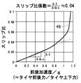
- a characteristic line 45 in FIG. 12 corresponds to the slip ratio range of 0 to 0.1 in the characteristic line 44 in FIG. Note that the characteristics shown in FIGS. 11 and 12 change according to the type and specifications of the vehicle 1, the type and specifications of tires, and the like. In the embodiment, a vehicle 1 and tires having characteristics shown in FIGS. 11 and 12 will be described as an example.
- Equation 13 is obtained from the equation of motion.
- the slip ratio coefficient kws is 0.04.
- the slip ratio calculator 35 calculates the slip ratio (second slip ratio) of each wheel based on the tire characteristics by multiplying the corrected longitudinal acceleration Gxf of each wheel by the slip ratio coefficient kws.
- the practical range is set to a linear range, for example, up to a slip ratio of 0.02 (small slip range). That is, since the slip ratio coefficient kws is linear in this practical range, the slip ratio coefficient kws is approximated linearly and used.
- the slip ratio distribution calculator 39 calculates the distribution ratio
- the third slip ratio calculator 40 distributes the second slip ratio calculated by the second slip ratio calculator 38 to each wheel.
- the second slip ratio calculator 38 calculates the calculated slip ratio, that is, the second slip ratio calculated based on the tire characteristics (slip ratio coefficient) and the longitudinal acceleration (corrected longitudinal acceleration) shown in FIG. Output to the third slip ratio calculator 40 .
- the brake operation flag and the first slip ratio are input to the slip ratio distribution calculator 39 .
- the slip ratio distribution calculator 39 calculates the slip ratio of each wheel based on the first slip ratio, that is, the slip ratio of each wheel calculated from the wheel speed.
- the slip ratio distribution calculator 39 does not obtain the slip ratio, but calculates only the distribution (ratio) of the slip ratio of each wheel. That is, the first slip ratio calculated by the vehicle XY plane state estimator 24 using Equation 2 described above can be calculated for each wheel. The accuracy is low for asking. However, the rough distribution of the slip ratio of each wheel does not deviate greatly. Therefore, the slip ratio distribution calculator 39 calculates the slip ratio of each wheel from the first slip ratio of each wheel.
- the slip ratio distribution calculator 39 calculates the ratio (distribution) of the slip ratio of each wheel using the following equation (17).
- R ⁇ corresponds to the ratio
- ⁇ corresponds to the slip ratio (first slip ratio).
- the suffix “oo” corresponds to one of "FL", “FR”, “RL” and “RR” which are the positions of the wheels 3 and 4.
- the ratio R ⁇ of the left front wheel 3 is “R ⁇ FL”
- the slip ratio (first slip ratio) is " ⁇ FL ".
- the slip ratio distribution calculator 39 outputs the calculated ratio (distribution) of the slip ratio of each wheel, that is, the ratio R ⁇ FL , the ratio R ⁇ FR , the ratio R ⁇ RL , and the ratio R ⁇ RR to the third slip ratio calculator 40 .
- the second slip ratio and the ratio of the slip ratios of the wheels are input to the third slip ratio calculator 40 .
- the third slip ratio calculator 40 calculates the second slip ratio (slip ratio of each wheel based on tire characteristics) calculated by the second slip ratio calculator 38 and the ratio calculated by the slip ratio distribution calculator 39 (slip of each wheel).
- the slip ratio of each wheel is calculated based on the ratio of the ratio). Specifically, the slip ratio (third slip ratio) of each wheel is calculated by multiplying the second slip by the ratio for each wheel.
- the slip ratio calculated by the third slip ratio calculating unit 40 is the slip ratio of each wheel obtained by correcting (distributing to each wheel) the slip ratio (second slip ratio) based on the longitudinal acceleration of the vehicle body and the tire characteristics, That is, it corresponds to the slip ratio (third slip ratio) calculated from the longitudinal acceleration and tire characteristics.
- the third slip ratio calculator 40 outputs the calculated third slip ratio to each wheel slip ratio selector 42 .
- the slip ratio (third slip ratio) calculated from the longitudinal acceleration and tire characteristics is gradually replaced with the slip ratio (first slip ratio) based on the wheel speed according to the slip ratio at that time.
- the slip ratio replacement coefficient calculation section 34, the multiplication section 41, and the wheel slip ratio selection section 42 are provided. This prevents divergence of the vertical motion state quantity when the slip ratio becomes a medium slip (for example, 0.02 or more).
- the multiplication unit 41 and each wheel slip ratio selection unit 42 convert the slip ratio (third slip ratio) based on the longitudinal acceleration to the slip ratio (first slip ratio) based on the wheel speed in accordance with the slip ratio obtained by the wheel speed.
- switch to A slip ratio (first slip ratio) based on the wheel speed and a slip ratio replacement coefficient are input to the multiplier 41 .
- the multiplication unit 41 calculates a slip ratio (fourth slip ratio) based on the wheel speed for switching by multiplying the slip ratio (first slip ratio) based on the wheel speed and the slip ratio replacement coefficient.
- the multiplication unit 41 outputs the calculated fourth slip ratio (first slip ratio for replacement) to the wheel slip ratio selection unit 42 .
- a brake operation flag, a third slip ratio, and a fourth slip ratio are input to each wheel slip ratio selection unit 42 .
- Each wheel slip ratio selection unit 42 selects either the third slip ratio or the fourth slip ratio according to the brake operation situation, and uses the selected slip ratio as the final slip ratio (fifth slip ratio). , to the slip-caused wheel speed calculator 36 . That is, each wheel slip ratio selection unit 42 compares the third slip ratio and the fourth slip ratio, selects a slip ratio with a large value while the brake is not operating, and selects a slip ratio with a small value while the brake is operating. do.
- the wheel slip ratio selector 42 outputs the selected slip ratio (the third slip ratio or the fourth slip ratio) to the slip-caused wheel speed calculator 36 as the fifth slip ratio.
- the reason why the magnitude is divided according to the brake operating state is that even if the sign of acceleration changes depending on the brake operating state, a larger slip ratio (slip ratio with a large absolute value) can be selected.
- the reason why the wheel slip ratio selector 42 selects the third slip ratio and the fourth slip ratio in other words, the reason why the slip ratio determined from the wheel speed is not always used is the slip ratio determined from the wheel speed. This is because the vertical motion component (wheel speed caused by vertical motion) is also included. That is, since the slip ratio determined from the wheel speed also includes a vertical motion component (wheel speed caused by vertical motion), it is difficult to estimate the state of the vertical motion if the slip ratio determined from the wheel speed is used at 100%. .
- the suspension control unit 21 has the slip state detection device 43 for detecting the slip state of the wheels 3,4.
- the slip state detection device 43 includes a second slip ratio calculator 38 as tire characteristic-considered slip ratio determination means, and a slip ratio distribution calculator 39 and a third slip ratio calculator 40 as corrected slip ratio determination means.
- the second slip ratio calculator 38 calculates a tire characteristic-considered slip ratio (second slip ratio) according to a longitudinal acceleration signal (longitudinal acceleration) of the vehicle 1 detected by the longitudinal acceleration sensor 11 and a tire characteristic (slip ratio coefficient).
- Ask for The slip ratio distribution calculation unit 39 and the third slip ratio calculation unit 40 determine the tire characteristic-considered slip ratio (second slip ratio) according to the rotation speed signal (wheel speed) of each wheel 3, 4.
- a corrected slip ratio (third slip ratio) for each wheel is obtained by correcting with a ratio (more specifically, a ratio of slip ratios). Therefore, it is possible to improve the accuracy of the slip ratios of the wheels 3 and 4 and, in turn, the slip-caused wheel speeds calculated based on the slip ratios.
- the longitudinal acceleration sensor 11 as longitudinal acceleration detection means, the wheel speed sensor 13 as wheel rotation speed detection means, the suspension control unit 21 as a control device, the shock absorber 7 as an actuator, 10 (a damping force adjustment mechanism such as a damping force adjustment valve and a solenoid for adjusting the damping force).
- the longitudinal acceleration sensor 11 detects longitudinal acceleration of the vehicle 1 and outputs a longitudinal acceleration signal.
- a wheel speed sensor 13 detects the rotational speed of each wheel 3,4 and outputs a rotational speed signal of each wheel 3,4.
- the suspension control unit 21 receives the longitudinal acceleration signal and the rotation speed signal of each wheel 3,4.
- the suspension control unit 21 (for example, the second slip ratio calculator 38) obtains a tire characteristic consideration slip ratio (second slip ratio) from the input longitudinal acceleration signal (longitudinal acceleration) and tire characteristics (slip ratio coefficient). .
- the suspension control unit 21 (for example, the slip ratio distribution calculation unit 39 and the third slip ratio calculation unit 40) corrects (distributes) the tire characteristic-considered slip ratio according to the rotational speed signals (wheel speeds) of the wheels 3 and 4. ) to obtain the corrected slip ratio (third slip ratio) of each wheel.
- Suspension control unit 21 (for example, slip-caused wheel speed calculator 36, subtractor 37, third wheel speed calculator 32, vertical motion estimator 27) is based on rotational speed signals (wheel speeds) of wheels 3 and 4. Then, the estimated vertical motion of the vehicle body 2 is corrected based on the corrected slip ratio of each wheel.
- a suspension control unit 21 (for example, a suspension control section 23 ) outputs a control signal based on the corrected vertical movement of the vehicle body 2 .
- Shock absorbers 7 and 10 (damping force adjusting mechanisms) are provided between the vehicle body 2 and the wheel 3 and 4 side members.
- the shock absorbers 7 and 10 change the state of the vehicle body 2 in response to the input from the wheel 3 and 4 side members according to the control signal from the suspension control unit 21 . Therefore, in the embodiment, the accuracy of estimating the state of the vehicle body 2 in the vertical direction can be improved, and the ride comfort and steering stability of the vehicle 1 can be improved.
- the slip state detection device and suspension control device (suspension system) according to the embodiment have the configuration as described above, and the operation thereof will be described next.
- the change in behavior is detected by the longitudinal acceleration sensor 11, the lateral acceleration sensor 12, the wheel speed sensor 13, the yaw rate sensor 15, etc. mounted on the vehicle 1. detected by Further, the operation of the driver of the vehicle 1 is detected by the steering angle sensor 14, the brake switch 16, and the like. Detection signals from these sensors 11 , 12 , 13 , 14 , 15 and switch 16 are input to suspension control unit 21 that controls buffers 7 , 10 via CAN 17 . Suspension control unit 21 outputs a control signal to dampers 7 and 10 for controlling the damping force of dampers 7 and 10 based on the input signal. Thereby, the ride comfort and steering stability of the vehicle 1 can be improved.
- the slip state detection device 43 of the suspension control unit 21 obtains the "tire characteristic consideration slip ratio (second slip ratio)" according to the longitudinal acceleration of the vehicle 1 and the tire characteristic.
- the slip ratio of each wheel can be obtained with high accuracy as the "correction slip ratio (third slip ratio)". Thereby, the estimation accuracy of the slip ratio can be improved.
- the suspension control unit 21 sets the "slip ratio considering tire characteristics (second slip ratio)" obtained from the longitudinal acceleration of the vehicle 1 and the tire characteristics to the rotational speed of each wheel 3, 4 (wheel The “corrected slip ratio (third slip ratio)” of each wheel is obtained by correcting according to the speed), and based on this "corrected slip ratio (third slip ratio)", the rotational speed of each wheel 3, 4
- the estimated “vertical movement of the vehicle body 2" is corrected. Therefore, the state of the vehicle body 2 in the vertical direction can be obtained with high accuracy. As a result, the accuracy of estimating the state of the vehicle body 2 in the vertical direction can be improved.
- the suspension control unit 21 controls the shock absorbers 7 and 10 (damping force adjustment mechanism) that change the state of the vehicle body 2 based on the corrected vertical movement of the vehicle body 2, the ride comfort and steering of the vehicle 1 are improved. Can improve stability.
- tire characteristics are learned (machine learning) based on detected values such as wheel speed, vehicle speed, and acceleration detected while the vehicle 1 is running, and the tire characteristics are varied according to the learning result.
- the tire characteristics change when the tires of the vehicle 1 are replaced, for example, when standard tires (summer tires) are replaced with studless tires (winter tires), eco tires, sports driving tires (high grip tires), or the like. there is a possibility. Therefore, when a tire is replaced (that is, when the tire characteristics are changed), the tire characteristics settings are changed as necessary to correspond to the new tire type, specifications, and the like.
- the dampers 7 and 10 are damping force adjustable hydraulic dampers, that is, hydraulic semi-active dampers are used as an example.
- the dampers (actuators) are not limited to this, and other types of semi-active dampers such as ER dampers (electrorheological fluid dampers) may be used.
- shock absorbers (actuators) include, for example, hydraulic actuators for full active dampers, air springs for air suspension devices, stabilizers and adjustment actuators for adjusting the effectiveness of the stabilizers, linear motors that make up electromagnetic suspensions, etc. (wheel-side member) can be used.
- slip state detection device and suspension control device based on the above-described embodiments, for example, the following modes are conceivable.
- a first aspect of the present invention is a slip state detection device, comprising: a tire characteristic-considered slip ratio determination unit that determines a tire characteristic-considered slip ratio according to a longitudinal acceleration of a vehicle detected by a longitudinal acceleration detection unit and a tire characteristic; a corrected slip ratio determination unit that corrects the tire characteristic-considered slip ratio with the slip ratio of each wheel obtained according to the rotational speed signal of each wheel to determine the corrected slip ratio of each wheel.
- the "slip ratio considering tire characteristics” is determined according to the longitudinal acceleration of the vehicle and the tire characteristics, and the “slip ratio considering tire characteristics” is determined according to the rotational speed of each wheel.
- a "corrected slip ratio” for each wheel is obtained by correcting with the slip ratio of the wheel. Therefore, the slip ratio of each wheel can be obtained with high accuracy as the "correction slip ratio”. Thereby, the estimation accuracy of the slip ratio can be improved.
- the suspension control device comprises a longitudinal acceleration detector that detects longitudinal acceleration of the vehicle and outputs a longitudinal acceleration signal, and a longitudinal acceleration detector that detects the rotational speed of each wheel and detects the rotational speed of each wheel.
- a wheel rotation speed detection unit for outputting a signal, the longitudinal acceleration signal and the rotation speed signal of each wheel are inputted, a slip ratio considering tire characteristics is obtained from the inputted longitudinal acceleration signal and tire characteristics, and the tire A corrected slip ratio of each wheel is obtained by correcting the characteristic-considered slip ratio according to the rotation speed signal of each wheel, and the vertical movement of the vehicle body is estimated based on the rotation speed signal of each wheel, and the estimated vehicle body is obtained.
- a control device that corrects the vertical movement of based on the corrected slip ratio of each wheel and outputs a control signal based on the corrected vertical movement of the vehicle body, and is provided between the vehicle body and the wheel-side member, and the control and an actuator that changes the state of the vehicle body with respect to the input from the wheel-side member in response to a signal.
- the "corrected slip ratio" of each wheel is obtained by correcting the “slip ratio considering tire characteristics” obtained from the longitudinal acceleration of the vehicle and the tire characteristics according to the rotational speed of each wheel, Based on this "correction slip ratio", the "vertical movement of the vehicle body” estimated from the rotational speed of each wheel is corrected. Therefore, the state of the vehicle body in the vertical direction can be obtained with high accuracy. As a result, the accuracy of estimating the state of the vehicle body in the vertical direction can be improved. Moreover, since the actuators that change the state of the vehicle body are controlled based on the corrected vertical movement of the vehicle body, the ride comfort and steering stability of the vehicle can be improved.
- the present invention is not limited to the above-described embodiments, and includes various modifications.
- the above-described embodiments have been described in detail in order to explain the present invention in an easy-to-understand manner, and are not necessarily limited to those having all the configurations described.
- part of the configuration of one embodiment can be replaced with the configuration of another embodiment, and the configuration of another embodiment can be added to the configuration of one embodiment.
- Vehicle 2 Vehicle body 3 Front wheels (wheels) 4 Rear wheels (wheels) 7, 10 Shock absorbers (actuators) 11 Longitudinal acceleration sensor (longitudinal acceleration detection means) 12 Lateral acceleration sensor 13 Wheel speed sensor (wheel rotation speed detection means) 14 Steering Angle sensor 15 Yaw rate sensor 16 Brake switch 17 CAN 21 Suspension control unit (control device) 23 Suspension control unit 27 Vertical motion estimation unit 38 Second slip ratio calculation unit (tire characteristic consideration slip ratio determination means) 39 Slip ratio distribution calculation unit ( Corrected slip ratio determination means) 40 Third slip ratio calculator (corrected slip ratio determination means) 43 Slip state detection device
Landscapes
- Engineering & Computer Science (AREA)
- Mechanical Engineering (AREA)
- Transportation (AREA)
- Physics & Mathematics (AREA)
- Automation & Control Theory (AREA)
- Mathematical Physics (AREA)
- Chemical & Material Sciences (AREA)
- Combustion & Propulsion (AREA)
- Vehicle Body Suspensions (AREA)
- Control Of Driving Devices And Active Controlling Of Vehicle (AREA)
Abstract
Description








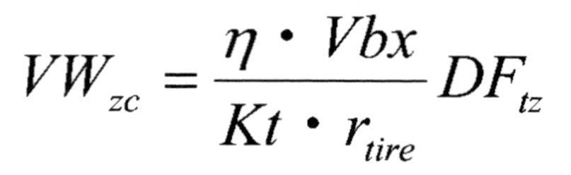
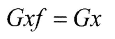




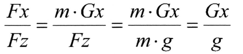


Claims (2)
- スリップ状態検出装置であって、
前後加速度検出部で検出された車両の前後加速度とタイヤ特性とに応じてタイヤ特性考慮スリップ比を求めるタイヤ特性考慮スリップ比確定部と、
前記タイヤ特性考慮スリップ比を、各車輪の回転速度信号に応じて求められる各車輪のスリップ比で補正して、各車輪の補正スリップ比を求める補正スリップ比確定部と、
を有するスリップ状態検出装置。 - サスペンション制御装置であって、
車両の前後加速度を検出して、前後加速度信号を出力する前後加速度検出部と、
各車輪の回転速度を検出して、各車輪の回転速度信号を出力する車輪回転速度検出部と、
前記前後加速度信号と前記各車輪の回転速度信号とを入力し、入力された前記前後加速度信号とタイヤ特性とからタイヤ特性考慮スリップ比を求め、前記タイヤ特性考慮スリップ比を、前記各車輪の回転速度信号に応じて補正して各車輪の補正スリップ比を求め、前記各車輪の回転速度信号に基づいて車体の上下動を推定し、推定された車体の上下動を前記各車輪の補正スリップ比に基づいて補正し、補正された車体の上下動に基づいた制御信号を出力する制御装置と、
車体と車輪側部材との間に設けられ、前記制御信号に応じて、前記車輪側部材からの入力に対する車体の状態を変化させるアクチュエータと、
を有するサスペンション制御装置。
Priority Applications (5)
| Application Number | Priority Date | Filing Date | Title |
|---|---|---|---|
| DE112022000824.5T DE112022000824T5 (de) | 2021-01-27 | 2022-01-20 | Schlupfzustandsdetektionseinrichtung und Federungssteuerungseinrichtung |
| US18/274,068 US12434524B2 (en) | 2021-01-27 | 2022-01-20 | Slip state detection apparatus and suspension control apparatus |
| JP2022578289A JP7369879B2 (ja) | 2021-01-27 | 2022-01-20 | スリップ状態検出装置およびサスペンション制御装置 |
| CN202280011887.7A CN116829381A (zh) | 2021-01-27 | 2022-01-20 | 滑移状态检测装置及悬架控制装置 |
| KR1020237024951A KR102761378B1 (ko) | 2021-01-27 | 2022-01-20 | 슬립 상태 검출 장치 및 서스펜션 제어 장치 |
Applications Claiming Priority (2)
| Application Number | Priority Date | Filing Date | Title |
|---|---|---|---|
| JP2021011007 | 2021-01-27 | ||
| JP2021-011007 | 2021-01-27 |
Publications (1)
| Publication Number | Publication Date |
|---|---|
| WO2022163471A1 true WO2022163471A1 (ja) | 2022-08-04 |
Family
ID=82653389
Family Applications (1)
| Application Number | Title | Priority Date | Filing Date |
|---|---|---|---|
| PCT/JP2022/001879 Ceased WO2022163471A1 (ja) | 2021-01-27 | 2022-01-20 | スリップ状態検出装置およびサスペンション制御装置 |
Country Status (6)
| Country | Link |
|---|---|
| US (1) | US12434524B2 (ja) |
| JP (1) | JP7369879B2 (ja) |
| KR (1) | KR102761378B1 (ja) |
| CN (1) | CN116829381A (ja) |
| DE (1) | DE112022000824T5 (ja) |
| WO (1) | WO2022163471A1 (ja) |
Cited By (1)
| Publication number | Priority date | Publication date | Assignee | Title |
|---|---|---|---|---|
| WO2026150766A1 (ja) * | 2025-01-10 | 2026-07-16 | Astemo株式会社 | 車両制御装置 |
Families Citing this family (4)
| Publication number | Priority date | Publication date | Assignee | Title |
|---|---|---|---|---|
| KR20240033478A (ko) * | 2022-09-05 | 2024-03-12 | 현대모비스 주식회사 | 차량의 제동장치 및 그 제어방법 |
| CN116424338B (zh) * | 2023-03-22 | 2025-09-12 | 东风越野车有限公司 | 车轮滑移率计算方法、装置、电子设备及存储介质 |
| WO2026105287A1 (ja) * | 2024-11-15 | 2026-05-21 | Astemo株式会社 | 車両挙動制御装置およびダンパ |
| CN119611375B (zh) * | 2024-12-31 | 2025-10-28 | 博世汽车部件(苏州)有限公司 | 车辆驾驶辅助方法和驾驶辅助单元 |
Citations (2)
| Publication number | Priority date | Publication date | Assignee | Title |
|---|---|---|---|---|
| WO2014045365A1 (ja) * | 2012-09-20 | 2014-03-27 | パイオニア株式会社 | スリップ率推定装置及びスリップ率推定方法 |
| JP2020117196A (ja) * | 2019-01-28 | 2020-08-06 | 日立オートモティブシステムズ株式会社 | 車両運動状態推定装置 |
Family Cites Families (17)
| Publication number | Priority date | Publication date | Assignee | Title |
|---|---|---|---|---|
| JP3623456B2 (ja) * | 2001-02-28 | 2005-02-23 | トヨタ自動車株式会社 | 車輌の走行制御装置 |
| JP3899987B2 (ja) | 2002-04-11 | 2007-03-28 | 株式会社豊田中央研究所 | 物理量推定装置及びタイヤ状態判定装置 |
| US20060108170A1 (en) | 2002-11-18 | 2006-05-25 | Hiroaki Ishikawa | Axle unit with slip sensor and slip meansurement method |
| US7640081B2 (en) * | 2004-10-01 | 2009-12-29 | Ford Global Technologies, Llc | Roll stability control using four-wheel drive |
| EP1897706B1 (en) * | 2005-06-17 | 2014-12-24 | Kabushiki Kaisha Bridgestone | Road surface state estimating method, road surface state estimating tire, road surface state estimating device, and vehicle control device |
| BRPI0717522B1 (pt) * | 2006-10-19 | 2020-07-14 | Toyota Jidosha Kabushiki Kaisha | Dispositivo de controle de amortecimento de vibração de um veículo e dispositivo para estimar um torque de roda que atua entre uma roda de um veículo e uma superfície de estrada |
| JP5339121B2 (ja) | 2008-08-25 | 2013-11-13 | 国立大学法人横浜国立大学 | スリップ率推定装置及びその方法と、スリップ率制御装置及びその方法 |
| JP6161476B2 (ja) | 2013-09-06 | 2017-07-12 | 本田技研工業株式会社 | サスペンション制御装置 |
| DE112017005121B4 (de) | 2016-12-09 | 2023-03-23 | Hitachi Astemo, Ltd. | Vorrichtung mit Kraftfahrzeug-Bewegungszustand-Bewertungsvorrichtung |
| JP6286092B1 (ja) * | 2017-05-30 | 2018-02-28 | 株式会社ショーワ | サスペンション制御装置、及びサスペンション装置。 |
| JP7028649B2 (ja) * | 2018-01-10 | 2022-03-02 | 日立Astemo株式会社 | 車両、車両運動状態推定装置および車両運動状態推定方法 |
| US10850586B2 (en) * | 2018-08-23 | 2020-12-01 | Tenneco Automotive Operating Company Inc. | Anti-roll moment distribution active suspension |
| EP3867087A4 (en) * | 2018-10-19 | 2022-07-13 | Clearmotion, Inc. | METHOD AND APPARATUS FOR OPERATING A SUSPENSION SYSTEM |
| US11964528B2 (en) * | 2019-01-03 | 2024-04-23 | ClearMotion, Inc. | Slip control via active suspension for optimization of braking and accelerating of a vehicle |
| JP6695481B1 (ja) * | 2019-06-25 | 2020-05-20 | 株式会社ショーワ | 接地荷重推定装置、制御装置および接地荷重推定方法 |
| TWI704029B (zh) | 2019-07-08 | 2020-09-11 | 聖杰國際股份有限公司 | 用於工具機之刀庫使用的刀桿鎖定暨解鎖結構 |
| US20210283969A1 (en) * | 2020-03-12 | 2021-09-16 | Mitsubishi Electric Research Laboratories, Inc. | Method and System for Achieving Active Suspension using Independently Actuated Wheels |
-
2022
- 2022-01-20 US US18/274,068 patent/US12434524B2/en active Active
- 2022-01-20 WO PCT/JP2022/001879 patent/WO2022163471A1/ja not_active Ceased
- 2022-01-20 JP JP2022578289A patent/JP7369879B2/ja active Active
- 2022-01-20 KR KR1020237024951A patent/KR102761378B1/ko active Active
- 2022-01-20 DE DE112022000824.5T patent/DE112022000824T5/de active Pending
- 2022-01-20 CN CN202280011887.7A patent/CN116829381A/zh active Pending
Patent Citations (2)
| Publication number | Priority date | Publication date | Assignee | Title |
|---|---|---|---|---|
| WO2014045365A1 (ja) * | 2012-09-20 | 2014-03-27 | パイオニア株式会社 | スリップ率推定装置及びスリップ率推定方法 |
| JP2020117196A (ja) * | 2019-01-28 | 2020-08-06 | 日立オートモティブシステムズ株式会社 | 車両運動状態推定装置 |
Cited By (1)
| Publication number | Priority date | Publication date | Assignee | Title |
|---|---|---|---|---|
| WO2026150766A1 (ja) * | 2025-01-10 | 2026-07-16 | Astemo株式会社 | 車両制御装置 |
Also Published As
| Publication number | Publication date |
|---|---|
| KR102761378B1 (ko) | 2025-01-31 |
| JP7369879B2 (ja) | 2023-10-26 |
| DE112022000824T5 (de) | 2023-11-23 |
| JPWO2022163471A1 (ja) | 2022-08-04 |
| CN116829381A (zh) | 2023-09-29 |
| US12434524B2 (en) | 2025-10-07 |
| US20250018760A1 (en) | 2025-01-16 |
| KR20230122136A (ko) | 2023-08-22 |
Similar Documents
| Publication | Publication Date | Title |
|---|---|---|
| JP7369879B2 (ja) | スリップ状態検出装置およびサスペンション制御装置 | |
| JP5809474B2 (ja) | 車体姿勢制御装置 | |
| US8718872B2 (en) | Vehicle attitude controller | |
| US11945428B2 (en) | Vehicle motion control apparatus | |
| US9375990B2 (en) | Suspension control device | |
| US8880293B2 (en) | Vehicle motion control apparatus and suspension control apparatus | |
| US9636965B2 (en) | Suspension system | |
| JPWO2018105399A1 (ja) | 車両運動状態推定装置 | |
| WO2014002444A1 (ja) | サスペンション制御装置 | |
| WO2020003550A1 (ja) | ステアリング制御装置及びステアリング装置 | |
| JP6285591B1 (ja) | サスペンション制御装置、および、サスペンション装置 | |
| JP5398581B2 (ja) | サスペンション制御装置 | |
| JP2020001605A (ja) | ステアリング制御装置及びステアリング装置 | |
| WO2019097732A1 (ja) | 車両状態推定装置、制御装置、サスペンション制御装置、サスペンション装置、ステアリング制御装置、及びステアリング装置 | |
| JP2013049362A (ja) | サスペンション制御装置 | |
| JP2020117196A (ja) | 車両運動状態推定装置 | |
| WO2022113426A1 (ja) | サスペンション制御装置、車両およびサスペンション制御方法 | |
| JP7685603B2 (ja) | 車両制御装置および車両制御システム | |
| JP7757569B2 (ja) | 車両挙動推定方法および車両挙動推定装置 | |
| JP2025142463A (ja) | サスペンション制御装置、サスペンション制御方法、およびサスペンション制御プログラム | |
| JP2015150912A (ja) | 換算係数取得装置 | |
| JP2024141928A (ja) | 加速度演算装置 | |
| JP2025128417A (ja) | 電子制御サスペンションの制御装置および制御方法 | |
| JP2020001692A (ja) | ラック軸力推定装置 |
Legal Events
| Date | Code | Title | Description |
|---|---|---|---|
| 121 | Ep: the epo has been informed by wipo that ep was designated in this application |
Ref document number: 22745692 Country of ref document: EP Kind code of ref document: A1 |
|
| ENP | Entry into the national phase |
Ref document number: 2022578289 Country of ref document: JP Kind code of ref document: A |
|
| ENP | Entry into the national phase |
Ref document number: 20237024951 Country of ref document: KR Kind code of ref document: A |
|
| WWE | Wipo information: entry into national phase |
Ref document number: 18274068 Country of ref document: US |
|
| WWE | Wipo information: entry into national phase |
Ref document number: 202280011887.7 Country of ref document: CN |
|
| WWE | Wipo information: entry into national phase |
Ref document number: 112022000824 Country of ref document: DE |
|
| 122 | Ep: pct application non-entry in european phase |
Ref document number: 22745692 Country of ref document: EP Kind code of ref document: A1 |
|
| WWG | Wipo information: grant in national office |
Ref document number: 18274068 Country of ref document: US |