WO2022163097A1 - シール部形成方法および装置の組立方法 - Google Patents
シール部形成方法および装置の組立方法 Download PDFInfo
- Publication number
- WO2022163097A1 WO2022163097A1 PCT/JP2021/043106 JP2021043106W WO2022163097A1 WO 2022163097 A1 WO2022163097 A1 WO 2022163097A1 JP 2021043106 W JP2021043106 W JP 2021043106W WO 2022163097 A1 WO2022163097 A1 WO 2022163097A1
- Authority
- WO
- WIPO (PCT)
- Prior art keywords
- forming
- seal portion
- heating
- sealing
- fipg
- Prior art date
- Legal status (The legal status is an assumption and is not a legal conclusion. Google has not performed a legal analysis and makes no representation as to the accuracy of the status listed.)
- Ceased
Links
Images

Classifications
-
- F—MECHANICAL ENGINEERING; LIGHTING; HEATING; WEAPONS; BLASTING
- F16—ENGINEERING ELEMENTS AND UNITS; GENERAL MEASURES FOR PRODUCING AND MAINTAINING EFFECTIVE FUNCTIONING OF MACHINES OR INSTALLATIONS; THERMAL INSULATION IN GENERAL
- F16J—PISTONS; CYLINDERS; SEALINGS
- F16J15/00—Sealings
- F16J15/02—Sealings between relatively-stationary surfaces
- F16J15/14—Sealings between relatively-stationary surfaces by means of granular or plastic material, or fluid
-
- F—MECHANICAL ENGINEERING; LIGHTING; HEATING; WEAPONS; BLASTING
- F16—ENGINEERING ELEMENTS AND UNITS; GENERAL MEASURES FOR PRODUCING AND MAINTAINING EFFECTIVE FUNCTIONING OF MACHINES OR INSTALLATIONS; THERMAL INSULATION IN GENERAL
- F16J—PISTONS; CYLINDERS; SEALINGS
- F16J15/00—Sealings
- F16J15/02—Sealings between relatively-stationary surfaces
- F16J15/021—Sealings between relatively-stationary surfaces with elastic packing
- F16J15/022—Sealings between relatively-stationary surfaces with elastic packing characterised by structure or material
-
- F—MECHANICAL ENGINEERING; LIGHTING; HEATING; WEAPONS; BLASTING
- F16—ENGINEERING ELEMENTS AND UNITS; GENERAL MEASURES FOR PRODUCING AND MAINTAINING EFFECTIVE FUNCTIONING OF MACHINES OR INSTALLATIONS; THERMAL INSULATION IN GENERAL
- F16J—PISTONS; CYLINDERS; SEALINGS
- F16J15/00—Sealings
- F16J15/02—Sealings between relatively-stationary surfaces
- F16J15/04—Sealings between relatively-stationary surfaces without packing between the surfaces, e.g. with ground surfaces, with cutting edge
-
- F—MECHANICAL ENGINEERING; LIGHTING; HEATING; WEAPONS; BLASTING
- F16—ENGINEERING ELEMENTS AND UNITS; GENERAL MEASURES FOR PRODUCING AND MAINTAINING EFFECTIVE FUNCTIONING OF MACHINES OR INSTALLATIONS; THERMAL INSULATION IN GENERAL
- F16J—PISTONS; CYLINDERS; SEALINGS
- F16J15/00—Sealings
- F16J15/02—Sealings between relatively-stationary surfaces
- F16J15/06—Sealings between relatively-stationary surfaces with solid packing compressed between sealing surfaces
- F16J15/10—Sealings between relatively-stationary surfaces with solid packing compressed between sealing surfaces with non-metallic packing
Definitions
- the present invention relates to a method of forming a sealing portion of electronic equipment or the like mounted on a vehicle and a method of assembling a device having this sealing portion.
- Patent Literature 1 discloses a configuration in which a so-called FIPG (Formed in Place Gasket) is used instead of the conventional molded gasket to seal between the body portion of the housing of the control device and the cover.
- FIPG Form in Place Gasket
- thermosetting FIPG is a kind of liquid adhesive, and usually a one-liquid thermosetting type is used.
- the thermosetting FIPG is cured in several hours by heating to about 120 to 130° C. in a furnace after being applied in the seal groove.
- thermosetting FIPG thermosetting FIPG
- the temperature required for curing is relatively high.
- a long curing time is required, which is a major obstacle to shortening the lead time.
- each FIPG forming step is performed in sequence, resulting in a very long working time.
- a method for forming a seal portion between members using an adhesive that is curable at room temperature by mixing a plurality of liquid agents comprising: is heated to a temperature higher than at least room temperature before or after mixing; .
- a sealing part forming method for forming a sealing part between members using an adhesive that is curable at room temperature by mixing a plurality of liquid agents, wherein the mixed adhesive is sealed. and a heating step of heating at least the entire member coated with the adhesive or a part of the member including at least the adhesive portion to a temperature higher than room temperature.
- an adhesive that can be cured at room temperature by mixing a plurality of liquid agents together such as a two-liquid room temperature curing type FIPG, is used, and by further heating this, a general one-liquid The curing time is shorter than that of the thermosetting FIPG.
- general one-liquid thermosetting FIPG requires a high temperature of 100 ° C or higher for curing, but it is relatively difficult to accelerate the curing of adhesives that cure even at room temperature by mixing multiple liquid agents. A low temperature is sufficient and the work becomes easy.
- FIG. 1 is an exploded perspective view of an electric actuator device for a power steering system to which the method of the present invention is applied;
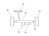
- FIG. 1 is an explanatory diagram showing an outline of a power steering device;
- FIG. 4 is an explanatory diagram of a second seal portion forming portion B between the housing and the motor cover; Explanatory drawing which shows the application
- FIG. 1 is an exploded perspective view of an electric actuator device 101 that applies a steering assist force to a steering mechanism (not shown) in an electric power steering system
- FIG. 2 is a schematic diagram of the electric power steering.
- This electric actuator device 101 includes a cylindrical motor section 1, an inverter power module 2, a circuit board 3 made of a multi-layered circuit board bent into a substantially U shape, and a connector member in which a plurality of connectors are assembled together. 4, and a motor cover 5 attached to one end of the motor section 1 so as to cover the inverter power module 2, the circuit board 3, and the connector member 4. As shown in FIG.
- the motor section 1 is a three-phase AC motor housed inside a cylindrical housing 7, and has a connecting section 6a such as a gear or a spline at the tip of a rotating shaft 6 protruding from the tip surface of the housing 7. , is connected to a steering mechanism, which will be described later, via this connecting portion 6a.
- the motor is a three-phase permanent magnet brushless motor, the stator has three-phase coils, and the permanent magnets are arranged on the outer peripheral surface of the rotor.
- the motor also has two series of coils and corresponding permanent magnets to provide redundancy.
- One end of the housing 7 opposite to the connecting portion 6a is configured as a bottom wall portion 7a having a horseshoe-shaped contour with a portion of the outer peripheral edge extending in the radial direction, and covers this bottom wall portion 7a.
- a motor cover 5 having a horseshoe-shaped contour corresponding to the bottom wall portion 7a is attached.
- the inverter power module 2 , the circuit board 3 , and the connector member 4 are accommodated in a space formed between the bottom wall portion 7 a and the motor cover 5 so as to overlap each other in the axial direction of the rotating shaft 6 .
- both end portions of each coil of the motor protrude toward the motor cover 5 through the bottom wall portion 7a as coil terminal portions 9, and are connected to corresponding terminals of the inverter power module 2, respectively. Since the motor includes two systems of coils, a total of 12 coil terminal portions 9 are arranged on the bottom wall portion 7a.
- the inverter power module 2 includes two inverter modules 2A that drive the motor, and a relay module 2B that serves as a neutral point relay for the coil. are placed. These inverter module 2A and relay module 2B are fixed to the end surface of the motor section 1 via a pressing member 2C. The coil terminal portions 9 of the coils described above are joined to corresponding terminals of these inverter power modules 2 by TIG welding or the like.
- the connector member 4 has three connectors oriented in the same direction along the axial direction of the rotating shaft 6 . More specifically, a power supply connector 4a located in the center, a sensor input connector 4b to which signals from sensors (for example, a steering angle sensor, a torque sensor, etc.) arranged on the steering mechanism side are input, and other sensors in the vehicle. A communication connector 4c for communication (for example, CAN communication) with a control device is provided. These connectors 4 a , 4 b , 4 c protrude outside through an opening 8 of the motor cover 5 .
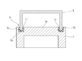
- FIPG which will be described later, is applied to the surrounding first seal portion forming portion A. As shown in FIG. This seals the housing 7 containing the motor. When the motor cover 5 is fixed to the housing 7 , the FIPG is also applied to the second sealing portion forming portion B between the opening edge 5 a of the motor cover 5 and the housing 7 . A seal groove 7b filled with FIPG is provided around the bottom wall portion 7a of the housing 7 as a second seal portion forming portion B. As shown in FIG.
- FIG. 1 the housing 7 and the motor cover 5 correspond to exterior members in the claims, and the motor, coil terminal portion 9 and the like correspond to internal structures.
- FIG. 2 schematically shows the configuration of an electric power steering device including the electric actuator device 101 described above, and corresponds to a top view of the vehicle.
- a rack shaft 103 extending in the width direction of the vehicle is accommodated in a rack case 102, and an electric actuator device 101 is attached to the outer surface of the rack case 102 via a speed reducer 104.
- the electric actuator device 101 operates based on detection signals from a steering angle sensor and a torque sensor (not shown), and the rack shaft 103 axially moves via the speed reducer 104 .
- the steered wheels (front wheels) 106 are steered.
- the electric actuator device 101 is attached to the electric power steering device in such a posture that the rotating shaft 6 of the motor is parallel to the rack shaft 103 . Since the electric actuator device 101 is thus in a position to receive rainwater or the like, water-resistant seals are required at the first seal portion forming portion A and the second seal portion forming portion B described above.
- thermosetting FIPG material instead of the conventional one-liquid thermosetting FIPG material, a silicone-based adhesive that can be cured at room temperature by mixing a first liquid agent and a second liquid agent together is used for forming these seal portions.
- a two-liquid room temperature curable FIPG is used. The curing time is shortened by heating to a temperature higher than room temperature before or after the application.
- the formation of the seal portion at the first seal portion forming portion A, that is, the first seal portion forming process is performed before the inverter power module 2, the circuit board 3, and the like are attached.
- Formation of the seal portion at the second seal portion forming portion B, that is, the second seal portion forming step is performed when the motor cover 5 is attached after the inverter power module 2, the circuit board 3, and the like are attached.
- the first liquid agent and the second liquid agent are separately heated to 60° C. and mixed using a line-type static mixer.
- a static mixer is a mixer in which a large number of spiral elements twisted 180° are continuously arranged in an elongated circular tube having two liquid inlets, and a liquid agent flows through the circular tube. Effective mixing of the two liquid agents is achieved by the division, conversion, and reversal action of the element.
- the tip of the static mixer serves as a discharge port for the liquid agent after mixing.
- the mixed FIPG material at 60°C is applied to the first sealing portion forming portion A and left at room temperature.
- the curing time is shortened. For example, it is sufficiently cured in about 2 hours. After that, the inverter power module 2, the circuit board 3 and the connector member 4 are attached.
- the first liquid agent and the second liquid agent are separately heated to 60°C and mixed using a line-type static mixer.
- the mixed 60° C. FIPG material is applied to the two second sealing portion forming locations B (that is, around the seal groove 7b of the housing 7 and the connector member 4), and the motor cover 5 is attached immediately. and leave at room temperature.
- the curing time is shortened. For example, it is sufficiently cured in about 2 hours. After that, a predetermined airtightness test is performed to confirm whether the sealing performance is sufficient.
- FIG. 3 is a simplified explanatory diagram showing the seal groove 7b of the housing 7 and the motor cover 5 as the second seal portion forming portion B. As shown, the seal groove 7b is coated or filled with the FIPG 11. The opening edge 5a of the motor cover 5 is fitted here.
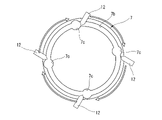
- FIG. 4 is an explanatory diagram of the process of applying the FIPG 11 to the seal groove 7b of the housing 7.
- a plurality of nozzles 12 are used to discharge the FIPG material before hardening, and these nozzles 12 are indicated by arrows.
- Application is performed by moving along the seal groove 7b as shown.
- excess material is prevented from overflowing due to dripping.
- the FIPG material is left to stand at room temperature after being applied.
- a storage room maintained at a temperature slightly higher than room temperature (eg, 20° C.), for example, 40° C., may be prepared and left in this 40° C. atmosphere.
- room temperature in the factory where various machines and devices operate is higher than the outside temperature, and can be, for example, about 30.degree.
- the heating temperature for the two liquid agents was set to 60°C. More preferably, the curing time can be sufficiently shortened by heating to a temperature of 50° C. or higher. On the other hand, if the temperature is excessively high, exceeding 100°C, it takes longer than the curing time until the temperature drops to a temperature that can be handled in the next step, which is rather inefficient. is preferably Therefore, the heating temperature is preferably 30°C to 70°C. Moreover, from the viewpoint of shortening the curing time when left at room temperature, it is desirable that the temperature is higher than room temperature by 10° C. or more.
- the two liquid agents are individually heated and then mixed, but the mixed materials may be discharged while being heated by a heater provided in the nozzle 12 without being heated.
- the first liquid agent and the second liquid agent are separately heated to 60° C. and mixed using a line-type static mixer.
- the mixed FIPG material at 60° C. is applied to the first sealing portion forming portion A and left at room temperature.
- the curing time is shortened. For example, it is sufficiently cured in about 2 hours.
- the inverter power module 2, the circuit board 3 and the connector member 4 are attached.
- the first liquid agent and the second liquid agent are mixed using a line-type static mixer without heating.
- the mixed FIPG material is applied to the two second sealing portion forming locations B (that is, around the seal groove 7b of the housing 7 and the connector member 4), and the motor cover 5 is attached immediately.
- the second sealing portion forming portion B is locally heated from the outside using a heating device such as a dryer that discharges hot air.
- a heating device such as a dryer that discharges hot air.
- the above-described second heating process may be added to each sealing portion forming process.
- the first liquid agent and the second liquid agent are mixed using a line-type static mixer without heating.
- the mixed FIPG material is applied to the first sealing portion forming portion A. Then, the inverter power module 2, the circuit board 3 and the connector member 4 are attached without waiting for sufficient hardening.
- the first liquid agent and the second liquid agent are mixed using a line-type static mixer without heating.
- the mixed FIPG material is applied to the two second sealing portion forming locations B (that is, around the seal groove 7b of the housing 7 and the connector member 4), and the motor cover 5 is attached immediately.
- the entire assembled electric actuator device 101 is heated in a heating furnace to a relatively low temperature (for example, about 60.degree. C. to 70.degree. C.).
- a relatively low temperature for example, about 60.degree. C. to 70.degree. C.
- the above-described second heating step may be added to the second sealing portion forming step.
- the conventional one-liquid thermosetting FIPG material may be used for the second sealing portion forming portion B.
- the present invention is not limited to the above embodiment, and various modifications are possible.
- the method of the first sealing portion forming step and the method of the second sealing portion forming step in each of the above-described embodiments can be appropriately combined and carried out.
- an example of application to the formation of a seal portion of the electric actuator device 101 for a power steering system has been described, but the present invention can be applied to seals of any device or structure.
- the present invention A sealing part forming method for forming a sealing part between members using an adhesive that can be cured at room temperature by mixing a plurality of liquid agents, a heating step of heating the plurality of liquid agents to a temperature higher than at least room temperature before or after mixing; an application step of applying the mixed adhesive to the sealing portion formation location in this heated state; Prepare.
- the invention provides A sealing part forming method for forming a sealing part between members using an adhesive that can be cured at room temperature by mixing a plurality of liquid agents, an application step of applying the mixed adhesive to the sealing portion formation location; a heating step of heating the entire member coated with the adhesive or at least a portion of the member including the adhesive portion to a temperature higher than at least room temperature; Prepare.
- the heating temperature in the heating step is 30°C to 70°C.
- the heating temperature in the heating step is at least 10°C higher than room temperature and does not exceed 70°C.
- the present invention provides An internal structure is accommodated in an exterior member, and as sealing portion formation locations using an adhesive, a first seal portion formation location in the internal structure and a second seal portion for sealing the exterior member are provided.
- a method of assembling a device comprising: a first seal portion forming step of forming a seal portion at the first seal portion forming location; After the first sealing portion forming step, a second sealing portion forming step of forming a sealing portion at the second sealing portion forming location; with The sealing portion forming method according to any one of claims 1 to 5 is applied to at least the first sealing portion forming step.
- the seal portion forming method according to claim 1 is applied to the first seal portion forming step
- the sealing portion forming method according to claim 2 is applied to the second sealing portion forming step.
Landscapes
- Engineering & Computer Science (AREA)
- General Engineering & Computer Science (AREA)
- Mechanical Engineering (AREA)
- Casings For Electric Apparatus (AREA)
- Motor Or Generator Frames (AREA)
Abstract
Description
第1のシール部形成工程として、第1の液剤と第2の液剤とを個別に60℃に加温し、ライン型のスタティックミキサを用いて混合する。スタティックミキサは、180°捩った形をなすスパイラル状のエレメントを2つの液入口を有する細長い円管の中に多数個連続的に配置した構成のミキサであり、円管の中を液剤が流れる際にエレメントによる分割・転換・反転作用を受けることで2つの液剤の効果的な混合がなされる。スタティックミキサの先端部が混合後の液剤の吐出口となる。
第1のシール部形成工程として、第1の液剤と第2の液剤とを個別に60℃に加温し、ライン型のスタティックミキサを用いて混合する。混合した60℃のFIPG材料を、第1のシール部形成箇所Aに塗布し、室温で放置する。予め加温しておくことで、硬化時間が短くなり、例えば2時間程度で十分に硬化する。その後、インバータ・パワーモジュール2、回路基板3およびコネクタ部材4を取り付ける。
第1のシール部形成工程として、第1の液剤と第2の液剤とを加温せずにライン型のスタティックミキサを用いて混合する。混合したFIPG材料を、第1のシール部形成箇所Aに塗布する。そして、十分な硬化を待たずに、インバータ・パワーモジュール2、回路基板3およびコネクタ部材4を取り付ける。
複数の液剤を互いに混合することで常温下で硬化可能な接着剤を用いて部材間のシール部を形成するシール部形成方法であって、
上記複数の液剤を、その混合前もしくは混合後に、少なくとも室温よりも高い温度に加温する加温工程と、
この加温された状態で、混合した接着剤をシール部形成箇所に塗布する塗布工程と、
を備える。
複数の液剤を互いに混合することで常温下で硬化可能な接着剤を用いて部材間のシール部を形成するシール部形成方法であって、
混合した接着剤をシール部形成箇所に塗布する塗布工程と、
接着剤が塗布された部材の全体もしくは少なくとも接着剤部分を含む部材の一部を、少なくとも室温よりも高い温度に加温する加温工程と、
を備える。
外装部材の中に内部構造物が収容され、接着剤を用いたシール部形成箇所として、上記内部構造物における第1のシール部形成箇所と、上記外装部材をシールするための第2のシール部形成箇所と、を備えた装置の組立方法であって、
上記第1のシール部形成箇所にシール部を形成する第1のシール部形成工程と、
この第1のシール部形成工程の後に、上記第2のシール部形成箇所にシール部を形成する第2のシール部形成工程と、
を備え、
少なくとも上記第1のシール部形成工程に、請求項1~5のいずれかに記載のシール部形成方法が適用される。
上記第1のシール部形成工程に請求項1に記載のシール部形成方法が適用され、
上記第2のシール部形成工程に請求項2に記載のシール部形成方法が適用される。
Claims (7)
- 複数の液剤を互いに混合することで常温下で硬化可能な接着剤を用いて部材間のシール部を形成するシール部形成方法であって、
上記複数の液剤を、その混合前もしくは混合後に、少なくとも室温よりも高い温度に加温する加温工程と、
この加温された状態で、混合した接着剤をシール部形成箇所に塗布する塗布工程と、
を備えてなるシール部形成方法。 - 複数の液剤を互いに混合することで常温下で硬化可能な接着剤を用いて部材間のシール部を形成するシール部形成方法であって、
混合した接着剤をシール部形成箇所に塗布する塗布工程と、
接着剤が塗布された部材の全体もしくは少なくとも接着剤部分を含む部材の一部を、少なくとも室温よりも高い温度に加温する加温工程と、
を備えてなるシール部形成方法。 - 上記加温工程における加温温度が、30℃~70℃である、請求項1または2に記載のシール部形成方法。
- 上記加温工程における加温温度が、室温よりも10℃以上高く、かつ70℃を越えない温度である、請求項1または2に記載のシール部形成方法。
- 請求項1または2に記載の各工程の後、上記加温工程における加温温度よりも相対的に低い温度に加温された雰囲気温度中に部材を放置する第2の加温工程、をさらに備えている請求項1または2に記載のシール部形成方法。
- 外装部材の中に内部構造物が収容され、接着剤を用いたシール部形成箇所として、上記内部構造物における第1のシール部形成箇所と、上記外装部材をシールするための第2のシール部形成箇所と、を備えた装置の組立方法であって、
上記第1のシール部形成箇所にシール部を形成する第1のシール部形成工程と、
この第1のシール部形成工程の後に、上記第2のシール部形成箇所にシール部を形成する第2のシール部形成工程と、
を備え、
少なくとも上記第1のシール部形成工程に、請求項1~5のいずれかに記載のシール部形成方法が適用される、装置の組立方法。 - 上記第1のシール部形成工程に請求項1に記載のシール部形成方法が適用され、
上記第2のシール部形成工程に請求項2に記載のシール部形成方法が適用される、
請求項6に記載の装置の組立方法。
Priority Applications (3)
| Application Number | Priority Date | Filing Date | Title |
|---|---|---|---|
| JP2022578075A JP7461517B2 (ja) | 2021-01-29 | 2021-11-25 | 装置の組立方法 |
| US18/262,723 US20240401699A1 (en) | 2021-01-29 | 2021-11-25 | Seal part forming method and device assembling method |
| CN202180092155.0A CN116802421A (zh) | 2021-01-29 | 2021-11-25 | 密封部形成方法和装置的装配方法 |
Applications Claiming Priority (2)
| Application Number | Priority Date | Filing Date | Title |
|---|---|---|---|
| JP2021-012671 | 2021-01-29 | ||
| JP2021012671 | 2021-01-29 |
Publications (1)
| Publication Number | Publication Date |
|---|---|
| WO2022163097A1 true WO2022163097A1 (ja) | 2022-08-04 |
Family
ID=82653149
Family Applications (1)
| Application Number | Title | Priority Date | Filing Date |
|---|---|---|---|
| PCT/JP2021/043106 Ceased WO2022163097A1 (ja) | 2021-01-29 | 2021-11-25 | シール部形成方法および装置の組立方法 |
Country Status (4)
| Country | Link |
|---|---|
| US (1) | US20240401699A1 (ja) |
| JP (1) | JP7461517B2 (ja) |
| CN (1) | CN116802421A (ja) |
| WO (1) | WO2022163097A1 (ja) |
Cited By (1)
| Publication number | Priority date | Publication date | Assignee | Title |
|---|---|---|---|---|
| JPWO2024057683A1 (ja) * | 2022-09-14 | 2024-03-21 |
Citations (3)
| Publication number | Priority date | Publication date | Assignee | Title |
|---|---|---|---|---|
| JP2003159907A (ja) * | 2001-11-27 | 2003-06-03 | Toyoda Mach Works Ltd | ハブユニット |
| JP2005336451A (ja) * | 2004-03-11 | 2005-12-08 | Hiroshi Okai | 速固着―後硬化型硬化性組成物及び該組成物の製造方法 |
| WO2020137111A1 (ja) * | 2018-12-25 | 2020-07-02 | 株式会社スリーボンド | 硬化性樹脂組成物、燃料電池およびシール方法 |
Family Cites Families (11)
| Publication number | Priority date | Publication date | Assignee | Title |
|---|---|---|---|---|
| US5717009A (en) * | 1994-01-21 | 1998-02-10 | Toshiba Silicone Co., Ltd. | Adhesive composition and process for curing the same |
| EP0745604A3 (en) * | 1995-05-29 | 1998-07-29 | Shin-Etsu Chemical Co., Ltd. | Room temperature curable fluoropolymer composition; and fluorine-containing organosilicon compounds, a method of producing the same, and room temperature curable silicone composition containing the same |
| EP1731572B1 (en) * | 2004-04-01 | 2016-06-29 | ThreeBond Fine Chemical Co., Ltd. | Curable composition and sealing method |
| CN101522789B (zh) * | 2006-10-05 | 2011-04-20 | 株式会社钟化 | 固化性组合物 |
| JP6938840B2 (ja) * | 2016-06-28 | 2021-09-22 | 株式会社スリーボンド | 硬化性樹脂組成物、燃料電池およびシール方法 |
| US10865297B2 (en) * | 2016-07-14 | 2020-12-15 | Threebond Co., Ltd. | Curable resin composition, cured product, fuel cell, and sealing method |
| CA3057824A1 (en) * | 2017-04-14 | 2018-10-18 | Threebond Co., Ltd. | Curable resin composition, and fuel cell and sealing method using the same |
| JP2019125617A (ja) * | 2018-01-12 | 2019-07-25 | トヨタ自動車株式会社 | 電気部品の製造方法及び電気部品 |
| JP7291468B2 (ja) * | 2018-10-31 | 2023-06-15 | 日立Astemo株式会社 | 電動駆動装置及び電動パワーステアリング装置 |
| JP7085458B2 (ja) * | 2018-11-02 | 2022-06-16 | 日立Astemo株式会社 | 電動駆動装置及び電動パワーステアリング装置 |
| JPWO2022064931A1 (ja) * | 2020-09-25 | 2022-03-31 |
-
2021
- 2021-11-25 JP JP2022578075A patent/JP7461517B2/ja active Active
- 2021-11-25 US US18/262,723 patent/US20240401699A1/en not_active Abandoned
- 2021-11-25 WO PCT/JP2021/043106 patent/WO2022163097A1/ja not_active Ceased
- 2021-11-25 CN CN202180092155.0A patent/CN116802421A/zh active Pending
Patent Citations (3)
| Publication number | Priority date | Publication date | Assignee | Title |
|---|---|---|---|---|
| JP2003159907A (ja) * | 2001-11-27 | 2003-06-03 | Toyoda Mach Works Ltd | ハブユニット |
| JP2005336451A (ja) * | 2004-03-11 | 2005-12-08 | Hiroshi Okai | 速固着―後硬化型硬化性組成物及び該組成物の製造方法 |
| WO2020137111A1 (ja) * | 2018-12-25 | 2020-07-02 | 株式会社スリーボンド | 硬化性樹脂組成物、燃料電池およびシール方法 |
Cited By (3)
| Publication number | Priority date | Publication date | Assignee | Title |
|---|---|---|---|---|
| JPWO2024057683A1 (ja) * | 2022-09-14 | 2024-03-21 | ||
| WO2024057683A1 (ja) * | 2022-09-14 | 2024-03-21 | 日立Astemo株式会社 | 電動駆動装置及び電動パワーステアリング装置 |
| JP7854057B2 (ja) | 2022-09-14 | 2026-04-30 | Astemo株式会社 | 電動駆動装置及び電動パワーステアリング装置 |
Also Published As
| Publication number | Publication date |
|---|---|
| JPWO2022163097A1 (ja) | 2022-08-04 |
| CN116802421A (zh) | 2023-09-22 |
| US20240401699A1 (en) | 2024-12-05 |
| JP7461517B2 (ja) | 2024-04-03 |
Similar Documents
| Publication | Publication Date | Title |
|---|---|---|
| US10424991B2 (en) | Drive device | |
| US9676408B2 (en) | Electric driving device and electric power steering apparatus equipped with the same | |
| JP6117661B2 (ja) | 電子制御装置 | |
| US11932324B2 (en) | Electric drive device of electric power steering apparatus | |
| US20130344736A1 (en) | Electrical connector with sealed pins | |
| JP5953758B2 (ja) | モータ装置およびその製造方法 | |
| CN108141982B (zh) | 电气设备的壳体及其制造方法 | |
| WO2015040868A1 (ja) | リードフレーム、リードフレームを使用した電子制御装置及びリードフレーム搭載方法 | |
| CN117044081A (zh) | 驱动装置 | |
| WO2016035755A1 (ja) | 電動モータとその制御装置との接続部品及びこれを用いた電動モータとその制御装置との接続構造、並びに、これを用いた電動パワーステアリング装置、電動アクチュエータ、及び、車両 | |
| CN105720748A (zh) | 驱动装置 | |
| JP7461517B2 (ja) | 装置の組立方法 | |
| WO2021059793A1 (ja) | 電子制御装置及び、電動駆動装置及び電動パワーステアリング装置 | |
| JP6099915B2 (ja) | 電子制御装置 | |
| JP6445066B2 (ja) | 電子制御装置 | |
| JP6295354B2 (ja) | 電子制御装置 | |
| US20220278587A1 (en) | Electronic control unit | |
| US20060028090A1 (en) | Motor | |
| JP4493665B2 (ja) | 制御装置一体型回転電機の製造方法 | |
| JP7041541B2 (ja) | 電動駆動装置及び電動パワーステアリング装置 | |
| JP7011957B2 (ja) | 車両搭載機器のコネクタ構造 | |
| JP6445068B2 (ja) | 電子制御装置 | |
| JP2025114252A (ja) | 駆動装置 | |
| JP6197924B2 (ja) | 電動モータとその制御装置との接続部品及びこれを用いた電動モータとその制御装置との接続構造、並びに、これを用いた電動パワーステアリング装置、電動アクチュエータ、及び、車両 | |
| US10811815B2 (en) | Production of a sealed plug by injecting adhesive during the joining of plug contacts and plug housing |
Legal Events
| Date | Code | Title | Description |
|---|---|---|---|
| 121 | Ep: the epo has been informed by wipo that ep was designated in this application |
Ref document number: 21923102 Country of ref document: EP Kind code of ref document: A1 |
|
| ENP | Entry into the national phase |
Ref document number: 2022578075 Country of ref document: JP Kind code of ref document: A |
|
| WWE | Wipo information: entry into national phase |
Ref document number: 202180092155.0 Country of ref document: CN |
|
| NENP | Non-entry into the national phase |
Ref country code: DE |
|
| 122 | Ep: pct application non-entry in european phase |
Ref document number: 21923102 Country of ref document: EP Kind code of ref document: A1 |