WO2022163089A1 - 玩具部品、人形玩具、及び、カバー部材 - Google Patents
玩具部品、人形玩具、及び、カバー部材 Download PDFInfo
- Publication number
- WO2022163089A1 WO2022163089A1 PCT/JP2021/042738 JP2021042738W WO2022163089A1 WO 2022163089 A1 WO2022163089 A1 WO 2022163089A1 JP 2021042738 W JP2021042738 W JP 2021042738W WO 2022163089 A1 WO2022163089 A1 WO 2022163089A1
- Authority
- WO
- WIPO (PCT)
- Prior art keywords
- protrusion
- toy
- notch
- doll
- toy part
- Prior art date
- Legal status (The legal status is an assumption and is not a legal conclusion. Google has not performed a legal analysis and makes no representation as to the accuracy of the status listed.)
- Ceased
Links
Images



Classifications
-
- A—HUMAN NECESSITIES
- A63—SPORTS; GAMES; AMUSEMENTS
- A63H—TOYS, e.g. TOPS, DOLLS, HOOPS OR BUILDING BLOCKS
- A63H3/00—Dolls
- A63H3/16—Dolls made of parts that can be put together
-
- A—HUMAN NECESSITIES
- A63—SPORTS; GAMES; AMUSEMENTS
- A63H—TOYS, e.g. TOPS, DOLLS, HOOPS OR BUILDING BLOCKS
- A63H3/00—Dolls
- A63H3/36—Details; Accessories
-
- A—HUMAN NECESSITIES
- A63—SPORTS; GAMES; AMUSEMENTS
- A63H—TOYS, e.g. TOPS, DOLLS, HOOPS OR BUILDING BLOCKS
- A63H3/00—Dolls
- A63H3/36—Details; Accessories
- A63H3/46—Connections for limbs
-
- A—HUMAN NECESSITIES
- A63—SPORTS; GAMES; AMUSEMENTS
- A63H—TOYS, e.g. TOPS, DOLLS, HOOPS OR BUILDING BLOCKS
- A63H3/00—Dolls
- A63H3/36—Details; Accessories
- A63H3/48—Mounting of parts within dolls, e.g. automatic eyes or parts for animation
Definitions
- the present invention relates to toy parts, doll toys and cover members.
- Patent Literature 1 describes that parts such as the body, arms, and legs of a toy doll are assembled from a plurality of toy parts.
- the present invention makes it possible to provide a model component having the structure described above and a doll toy using the model component.
- the present invention is a toy component configured by connecting a first member and a second member so as to be rotatable, wherein the first member is connected to the second member and is connected to a rotation shaft
- the second member has a first notch that engages the first protrusion
- the toy part has a first notch that engages with the first notch a third member having a first recess that is coupled to the exposed portion of the first projection in a state where the first projection is engaged with the third member;
- the member is fixedly attached to the second member by coupling the first protrusion and the first recess.
- the figure which shows an example of the doll toy corresponding to embodiment The figure which shows the appearance of the leg part of the doll toy corresponding to embodiment.
- FIG. 1 shows an example of the appearance of a doll toy corresponding to this embodiment.
- FIG. 1 is a schematic diagram showing a simplified appearance of a doll toy 100 according to an embodiment.
- the toy doll 100 has model parts such as a head 110, a body 111, arms 112, a waist 113, and legs 114, which are joined together. At least part of the individual parts 110 to 114 are supported so as to be rotatable (or rockable) with respect to adjacent parts.
- the head 110 is rotatably supported with respect to the body 111
- the arms 112 are supported with respect to the body 111 so as to be rotatable, tilt forward, and tilt backward.
- the leg portion 114 is rotatably supported with respect to the waist portion 113 .
- the leg portion 114 is further provided with a knee joint, and can be rotated so as to bend the above-knee portion and the below-the-knee portion.
- each part of the toy doll 100 is provided with a joint structure, and the user (for example, the owner of the toy doll 1) can put the toy doll 100 in a desired posture.
- the toy doll 100 can be attached with one or more decorative components.
- the decorative parts can also be configured in the same manner as the model parts of the doll toy described in this embodiment.
- Decorative parts include, for example, weapons such as swords and guns, armor such as shields, and the like.
- the doll toy corresponding to the present embodiment may be constructed by stacking the body portion 111, the arm portions 112, the leg portions 114, and the like.
- a part which may consist of one part or a part combining two parts
- the parts are connected by fitting, engaging, or the like, and sandwiching is unnecessary, so the problem of forgetting to sandwich does not occur.
- the part itself to be stacked may be configured as a single part, or may be configured by combining a plurality of parts.
- front front
- rear rear
- left left side
- right right
- top upper
- bottom lower
- these expressions are relative to the doll toy 1 .
- the front corresponds to the toy doll 100 front side
- the rear corresponds to the doll toy 100 back side.
- each model component that constitutes the doll toy 100 can be made of a thermoplastic resin such as ABS. Materials other than ABS (polyethylene, polystyrene, thermosetting resin, etc.) may also be used.
- each model part may be composed of an internal part made of ABS or the like and an external part made of a metal material covering the outside of the internal part. External parts are basically not directly connected to each other, and the relative positions of a plurality of external parts are determined through the same internal part by connecting external parts to internal parts. When connecting external parts together, they may be connected in advance by a sintering process.
- the external part can be composed of, for example, an alloy of titanium, aluminum and the rare earth element yttria. However, it is not limited to this, and may be other types of alloys in which at least a part of the combination is different or wholly different, or a single metal such as aluminum.
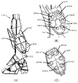
- FIG. 2A is a diagram showing an example of the configuration of the side surface of the leg portion 114.
- FIG. The leg portion 114 is composed of a plurality of members, and the members relating to the configuration of this embodiment will be described below.
- an above-knee member 201 which is a first member, is connected to a below-the-knee member 202, which is a second member, at the knee joint, and is configured to be rotatable so that the knee joint is bent.
- the left and right side surfaces of the knee joint are covered with a cover member 203, which is a third member, to shield the connecting portion from the outside.
- a projection member 204 which is a fourth member imitating a vernier, is rotatably connected to the knee joint.
- Vernier is used as a general term for injection devices, and specifically refers to auxiliary devices for attitude control of spacecraft.
- FIG. 2A shows only the left side, a similar cover member 203 is attached to the right side as well.
- FIG. 2B is an enlarged view of the knee joint portion of the leg 114, showing a state in which the cover member 203 is removed.
- the protrusion 201A constitutes a part of the above-the-knee member 201.
- the projecting portion 204 ⁇ /b>A constitutes a part of the projecting member 204 .
- Protrusions 205A to 205C form part of fixing member 205 that forms part of below-the-knee member 202 .
- an alignment mechanism 205F is formed to partition the protrusions 205A to 205C and the notches 205D and 205E. To facilitate alignment when mounting.
- Alignment mechanism 205F has a convex structure formed to define protrusions 205A to 205C and notches 205D and 205E. They can also be called protrusions or partitions.
- projections 201A and 204A are only detachably locked to the fixing member 205 when the cover member 203 is not present. can be removed. Therefore, when it is desired to paint these parts after assembly, they can be easily disassembled, painted as desired, and then reassembled.
- Projections 201A and 204A are fixed in arrangement by being coupled with cover member 203, and members 201 and 204 can be stably rotatable.
- FIG. 2C shows an example of the structure of the back surface of the cover member 203.
- Recesses 201A', 204A', 205A', 205B', and 205C' are recesses that are coupled to projections 201A, 204A, 205A, 205B, and 205C in FIG. 2B, respectively.
- the cover member 203 is fixedly attached to the below-the-knee member 202 by connecting each projection and each recess. Note that there is one recess not numbered, which is used to couple with 205B on the right side opposite to the left side shown in FIG. 2(A). That is, the right side surface of the leg portion 114 is configured symmetrically with FIG. 2(B).
- FIG. 3A shows an example of the configuration of the below-the-knee member 202.
- FIG. The below-the-knee member 202 is configured to include a fixing member 205 having projections 205A to 205C and cutouts 205D and 205E. Notch 205D engages projection 201A of above-knee member 201, and notch 205E engages projection 204A of projecting member 204. As shown in FIG.
- a slight protrusion is formed on the contact surface of the cutouts 205D and 205E with the protrusions, and the protrusions make it difficult for the protrusions engaged with the cutouts to come off.
- An example of the configuration of the convex portion is shown by enlarging the region surrounded by the dotted line in FIG. 3(A).
- FIG. 3B shows an example of the configuration of the above-the-knee member 201.
- the above-knee member 201 has a protrusion 201A, and the above-knee member 201 and the below-the-knee member 202 rotate about the protrusion 201A as a rotation axis by engaging the protrusion 201A with the notch 205D. movably connected. By this rotating motion, bending of the knee joint can be represented.
- FIG. 3C shows an example of the configuration of the projecting member 204 .
- the projecting member 204 has a projecting portion 204A, and by engaging the projecting portion 204A with the notch portion 205E, the projecting member 204 is rotatably connected to the fixing member 205 with the projecting portion 204A as a rotation axis. be done.
- Structures such as the notches 205D and 205E shown in FIG. 3 are generally called "C-shaped receivers". While there is an advantage that assembly and disassembly are easy, the force escapes in the opening direction, and the connection between members may be weakened. In particular, when the member is large or when the parts arranged on the lower side are heavy, it may be difficult to maintain the posture after the rotation. Therefore, in this embodiment, the cover member 203 is used to hold the protrusions 201A and 204A engaged with the cutouts 205D and 205E.
- Each member constituting the knee joint shown in FIG. 3 may be configured as a single member, or may be configured by combining a plurality of members.
- FIG. 4 is a diagram showing an example of a cross section of the leg portion 114 with the cover member 203 attached to the below-the-knee member 202.
- the cross section is set so as to pass through the connecting portion between the protrusion 201A and the recess 201A'.
- the contact between the notch 205D and the projection 201A is ensured only on the lower side, and is not ensured on the upper side.
- the recessed portion 201A' is formed so as to surround the outer periphery of the projecting portion 201A, and the width of the contact portion is sufficiently secured. In this way, after the protrusion 201A is temporarily fixed by the notch 205D of the C-shaped support, the protrusion 201A is completely enclosed by the recess 201A'.
- the above-knee member 201 and below-the-knee member 202 are rotated, they can be stopped at an arbitrary position, and a frictional force can be generated so as to maintain the posture.
- the connection between the cover member 203 and the fixing member 205 is also supported by the other four connections. The connection with the fixing member 205 is not released.
- FIG. 4 shows only the relationship between the protrusion 201A and the recess 201A', the relationship between the protrusion 204A and the recess 204A' is the same.
- the protrusion of the first member is The joint mechanism is covered with a cover member having a plurality of recesses to which a plurality of protrusions including the protrusion are coupled, while receiving the C-shaped receiver of the second member.
- the knee joint can be easily assembled and disassembled from a plurality of members, and can maintain any posture after assembly.
Landscapes
- Toys (AREA)
Applications Claiming Priority (2)
| Application Number | Priority Date | Filing Date | Title |
|---|---|---|---|
| JP2021-013572 | 2021-01-29 | ||
| JP2021013572A JP7038236B1 (ja) | 2021-01-29 | 2021-01-29 | 玩具部品、人形玩具、及び、カバー部材 |
Publications (1)
| Publication Number | Publication Date |
|---|---|
| WO2022163089A1 true WO2022163089A1 (ja) | 2022-08-04 |
Family
ID=80830740
Family Applications (1)
| Application Number | Title | Priority Date | Filing Date |
|---|---|---|---|
| PCT/JP2021/042738 Ceased WO2022163089A1 (ja) | 2021-01-29 | 2021-11-22 | 玩具部品、人形玩具、及び、カバー部材 |
Country Status (3)
| Country | Link |
|---|---|
| JP (3) | JP7038236B1 (https=) |
| CN (2) | CN117160049A (https=) |
| WO (1) | WO2022163089A1 (https=) |
Citations (6)
| Publication number | Priority date | Publication date | Assignee | Title |
|---|---|---|---|---|
| JP2011031078A (ja) * | 2010-11-17 | 2011-02-17 | Daisu Project:Kk | 人形玩具の2段階関節部材及び人形玩具 |
| JP2012157783A (ja) * | 2012-06-01 | 2012-08-23 | Tsuyoshi Maeda | 人体模型の腕部構造 |
| US20160348703A1 (en) * | 2015-06-01 | 2016-12-01 | Xyzprinting, Inc. | Joint structure |
| JP2019005542A (ja) * | 2017-06-28 | 2019-01-17 | 株式会社バンダイ | 人形玩具 |
| JP2019122505A (ja) * | 2018-01-15 | 2019-07-25 | 株式会社オビツ製作所 | 人形 |
| JP2020137613A (ja) * | 2019-02-27 | 2020-09-03 | 高原木材株式会社 | ブロック部材セット |
Family Cites Families (13)
| Publication number | Priority date | Publication date | Assignee | Title |
|---|---|---|---|---|
| WO2009116526A1 (ja) * | 2008-03-18 | 2009-09-24 | 株式会社コナミデジタルエンタテインメント | 変形玩具 |
| JP2009247656A (ja) * | 2008-04-08 | 2009-10-29 | Tomy Co Ltd | 玩具の関節構造 |
| CN202223880U (zh) * | 2011-05-24 | 2012-05-23 | 深圳市冉晨广告有限公司 | 一种组合式机械动力拼图卡 |
| JP3171849U (ja) | 2011-09-07 | 2011-11-17 | 株式会社バンダイ | 人形玩具 |
| DE202012003897U1 (de) * | 2012-04-05 | 2012-06-18 | Mammut Sports Group Ag | Sicherheitskarabiner mit Aushängesicherung |
| JP5379887B2 (ja) | 2012-06-22 | 2013-12-25 | 株式会社バンダイ | 人形体の腰部関節構造 |
| JP5661873B1 (ja) | 2013-07-12 | 2015-01-28 | 株式会社バンダイ | 模型キット |
| JP5771722B1 (ja) * | 2014-05-01 | 2015-09-02 | 株式会社バンダイ | 模型 |
| CN206492203U (zh) * | 2016-12-08 | 2017-09-15 | 广州庄臣动漫科技有限公司 | 一种变形玩具 |
| KR102593329B1 (ko) * | 2018-12-20 | 2023-10-25 | 엘지디스플레이 주식회사 | 멀티디스플레이의 갭 조절장치 및 이를 포함하는 멀티디스플레이 |
| JP6810781B1 (ja) * | 2019-10-11 | 2021-01-06 | 株式会社バンダイ | 可動構造及び組立玩具 |
| CN212119025U (zh) * | 2019-11-28 | 2020-12-11 | 英恒物业有限公司 | 电动玩具 |
| CN111389029A (zh) | 2020-04-17 | 2020-07-10 | 广州易腾动漫文化有限公司 | 一种转动关节及具有该转动关节的玩具 |
-
2021
- 2021-01-29 JP JP2021013572A patent/JP7038236B1/ja active Active
- 2021-11-22 WO PCT/JP2021/042738 patent/WO2022163089A1/ja not_active Ceased
- 2021-12-28 CN CN202311017331.1A patent/CN117160049A/zh active Pending
- 2021-12-28 CN CN202111622009.2A patent/CN114259739B/zh active Active
-
2022
- 2022-03-07 JP JP2022034748A patent/JP7621301B2/ja active Active
-
2025
- 2025-01-14 JP JP2025004911A patent/JP2025061264A/ja active Pending
Patent Citations (6)
| Publication number | Priority date | Publication date | Assignee | Title |
|---|---|---|---|---|
| JP2011031078A (ja) * | 2010-11-17 | 2011-02-17 | Daisu Project:Kk | 人形玩具の2段階関節部材及び人形玩具 |
| JP2012157783A (ja) * | 2012-06-01 | 2012-08-23 | Tsuyoshi Maeda | 人体模型の腕部構造 |
| US20160348703A1 (en) * | 2015-06-01 | 2016-12-01 | Xyzprinting, Inc. | Joint structure |
| JP2019005542A (ja) * | 2017-06-28 | 2019-01-17 | 株式会社バンダイ | 人形玩具 |
| JP2019122505A (ja) * | 2018-01-15 | 2019-07-25 | 株式会社オビツ製作所 | 人形 |
| JP2020137613A (ja) * | 2019-02-27 | 2020-09-03 | 高原木材株式会社 | ブロック部材セット |
Also Published As
| Publication number | Publication date |
|---|---|
| JP2022117501A (ja) | 2022-08-10 |
| CN114259739A (zh) | 2022-04-01 |
| CN117160049A (zh) | 2023-12-05 |
| JP7038236B1 (ja) | 2022-03-17 |
| JP7621301B2 (ja) | 2025-01-24 |
| JP2025061264A (ja) | 2025-04-10 |
| JP2022117080A (ja) | 2022-08-10 |
| CN114259739B (zh) | 2023-08-22 |
Similar Documents
| Publication | Publication Date | Title |
|---|---|---|
| JP3965384B2 (ja) | 玩具用組立ユニット及び形態変形玩具 | |
| JP6810781B1 (ja) | 可動構造及び組立玩具 | |
| JP7839042B2 (ja) | 玩具部品及び人形玩具 | |
| JP7601829B2 (ja) | 玩具部品、関節機構、人形玩具及び装飾部品 | |
| WO2022163089A1 (ja) | 玩具部品、人形玩具、及び、カバー部材 | |
| JP2025015665A (ja) | 玩具部品及び人形玩具 | |
| JP7821642B2 (ja) | 模型部品、及び人形玩具 | |
| JP7601996B2 (ja) | 構造体 | |
| JPS644388Y2 (https=) | ||
| JP7813936B1 (ja) | 模型玩具、及び模型部品 | |
| JP2021062214A (ja) | 可動構造及び組立玩具 | |
| JP7478296B1 (ja) | 模型玩具 | |
| JPS644387Y2 (https=) | ||
| JP2025146831A (ja) | 模型部品及び模型玩具 | |
| WO2025070268A1 (ja) | 模型玩具の支持体 | |
| JPH0341747Y2 (https=) | ||
| JP2022117501A5 (https=) | ||
| JPH0630233Y2 (ja) | 組立人形玩具 | |
| CN121243784A (zh) | 模型部件和模型玩具 | |
| JPS62101276A (ja) | 形態変化玩具 |
Legal Events
| Date | Code | Title | Description |
|---|---|---|---|
| 121 | Ep: the epo has been informed by wipo that ep was designated in this application |
Ref document number: 21923094 Country of ref document: EP Kind code of ref document: A1 |
|
| NENP | Non-entry into the national phase |
Ref country code: DE |
|
| 122 | Ep: pct application non-entry in european phase |
Ref document number: 21923094 Country of ref document: EP Kind code of ref document: A1 |