WO2022162997A1 - 車両制御装置 - Google Patents
車両制御装置 Download PDFInfo
- Publication number
- WO2022162997A1 WO2022162997A1 PCT/JP2021/032907 JP2021032907W WO2022162997A1 WO 2022162997 A1 WO2022162997 A1 WO 2022162997A1 JP 2021032907 W JP2021032907 W JP 2021032907W WO 2022162997 A1 WO2022162997 A1 WO 2022162997A1
- Authority
- WO
- WIPO (PCT)
- Prior art keywords
- cpu
- pattern
- load state
- temperature
- temperature difference
- Prior art date
- Legal status (The legal status is an assumption and is not a legal conclusion. Google has not performed a legal analysis and makes no representation as to the accuracy of the status listed.)
- Ceased
Links
Images

Classifications
-
- G—PHYSICS
- G06—COMPUTING OR CALCULATING; COUNTING
- G06F—ELECTRIC DIGITAL DATA PROCESSING
- G06F1/00—Details not covered by groups G06F3/00 - G06F13/00 and G06F21/00
- G06F1/16—Constructional details or arrangements
- G06F1/20—Cooling means
- G06F1/206—Cooling means comprising thermal management
-
- B—PERFORMING OPERATIONS; TRANSPORTING
- B60—VEHICLES IN GENERAL
- B60R—VEHICLES, VEHICLE FITTINGS, OR VEHICLE PARTS, NOT OTHERWISE PROVIDED FOR
- B60R16/00—Electric or fluid circuits specially adapted for vehicles and not otherwise provided for; Arrangement of elements of electric or fluid circuits specially adapted for vehicles and not otherwise provided for
- B60R16/02—Electric or fluid circuits specially adapted for vehicles and not otherwise provided for; Arrangement of elements of electric or fluid circuits specially adapted for vehicles and not otherwise provided for electric constitutive elements
- B60R16/023—Electric or fluid circuits specially adapted for vehicles and not otherwise provided for; Arrangement of elements of electric or fluid circuits specially adapted for vehicles and not otherwise provided for electric constitutive elements for transmission of signals between vehicle parts or subsystems
- B60R16/0231—Circuits relating to the driving or the functioning of the vehicle
- B60R16/0232—Circuits relating to the driving or the functioning of the vehicle for measuring vehicle parameters and indicating critical, abnormal or dangerous conditions
-
- B—PERFORMING OPERATIONS; TRANSPORTING
- B60—VEHICLES IN GENERAL
- B60W—CONJOINT CONTROL OF VEHICLE SUB-UNITS OF DIFFERENT TYPE OR DIFFERENT FUNCTION; CONTROL SYSTEMS SPECIALLY ADAPTED FOR HYBRID VEHICLES; ROAD VEHICLE DRIVE CONTROL SYSTEMS FOR PURPOSES NOT RELATED TO THE CONTROL OF A PARTICULAR SUB-UNIT
- B60W50/00—Details of control systems for road vehicle drive control not related to the control of a particular sub-unit, e.g. process diagnostic or vehicle driver interfaces
- B60W50/04—Monitoring the functioning of the control system
-
- B—PERFORMING OPERATIONS; TRANSPORTING
- B60—VEHICLES IN GENERAL
- B60W—CONJOINT CONTROL OF VEHICLE SUB-UNITS OF DIFFERENT TYPE OR DIFFERENT FUNCTION; CONTROL SYSTEMS SPECIALLY ADAPTED FOR HYBRID VEHICLES; ROAD VEHICLE DRIVE CONTROL SYSTEMS FOR PURPOSES NOT RELATED TO THE CONTROL OF A PARTICULAR SUB-UNIT
- B60W50/00—Details of control systems for road vehicle drive control not related to the control of a particular sub-unit, e.g. process diagnostic or vehicle driver interfaces
- B60W50/08—Interaction between the driver and the control system
- B60W50/14—Means for informing the driver, warning the driver or prompting a driver intervention
-
- B—PERFORMING OPERATIONS; TRANSPORTING
- B60—VEHICLES IN GENERAL
- B60W—CONJOINT CONTROL OF VEHICLE SUB-UNITS OF DIFFERENT TYPE OR DIFFERENT FUNCTION; CONTROL SYSTEMS SPECIALLY ADAPTED FOR HYBRID VEHICLES; ROAD VEHICLE DRIVE CONTROL SYSTEMS FOR PURPOSES NOT RELATED TO THE CONTROL OF A PARTICULAR SUB-UNIT
- B60W50/00—Details of control systems for road vehicle drive control not related to the control of a particular sub-unit, e.g. process diagnostic or vehicle driver interfaces
- B60W50/04—Monitoring the functioning of the control system
- B60W2050/041—Built in Test Equipment [BITE]
Definitions
- the present disclosure relates to a vehicle control device.
- the cooling mechanism described in Patent Document 1 can detect whether the CPU is being cooled normally by comparing the difference between the CPU temperature during actual operation and the temperature sensor IC temperature with a threshold value. You can (paragraph 0013, etc.). However, when this conventional cooling mechanism is applied to a vehicle control device, a temperature sensor IC is required in addition to the CPU. .
- the present disclosure provides a vehicle control device capable of detecting abnormal heat generation of a CPU or heat radiation abnormality of a cooling mechanism while suppressing an increase in size, an increase in the number of parts, and an increase in cost.
- One aspect of the present disclosure is a vehicle control device that includes a memory, a CPU, a temperature sensor built into the CPU, and a cooling mechanism that cools the CPU, wherein the memory is a load of the CPU.
- a standard pattern that is a temporal change of the state, a waiting time from the start of the standard pattern until the temperature sensor acquires the evaluation temperature, and the normal load state of the CPU is changed according to the standard pattern and the standby
- a standard temperature of the CPU when time elapses and a normal temperature difference from the standard temperature when at least one of the CPU and the cooling mechanism is normal are stored, and the CPU stores the load state of the CPU.
- the vehicle control device is characterized by calculating a difference and determining an abnormality when the temperature difference is greater than the normal temperature difference.
- a vehicle control device capable of detecting abnormal heat generation of a CPU or heat radiation abnormality of a cooling mechanism while suppressing an increase in size, an increase in the number of parts, and an increase in cost.
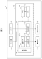
- FIG. 1 is a block diagram showing an embodiment of a vehicle control device according to the present disclosure
- FIG. FIG. 2 is a flowchart showing an example of processing executed by the vehicle control device in FIG. 1; 2 is a graph showing an example of temperature change of the CPU in FIG. 1; 2 is a graph showing an example of temperature change of the CPU in FIG. 1; 2 is a graph showing an example of temperature change of the CPU in FIG. 1; 2 is a graph showing an example of temperature change of the CPU in FIG. 1; 2 is a graph showing an example of temperature change of the CPU in FIG. 1; 2 is a graph showing an example of temperature change of the CPU in FIG. 1; 2 is a graph showing an example of temperature change of the CPU in FIG. 1; 2 is a graph showing an example of temperature change of the CPU in FIG. 1; 2 is a graph showing an example of temperature change of the CPU in FIG. 1; 2 is a graph showing an example of temperature change of the CPU in FIG. 1; 2 is a graph showing an example of temperature change of the
- FIG. 1 is a block diagram showing one embodiment of a vehicle control device according to the present disclosure.
- the sensor 2 includes, for example, an external sensor and a vehicle sensor.
- the external sensor includes, for example, a monocular camera, a stereo camera, a laser radar, a millimeter wave radar, an infrared sensor, an ultrasonic sensor, etc., and detects objects around the vehicle 1 .
- Vehicle sensors include, for example, a wheel speed sensor, an acceleration sensor, an angular velocity sensor, a global positioning system (GNSS) receiver, an accelerator sensor, a brake sensor, a steering angle sensor, etc., and detect the velocity, acceleration, angular velocity, position of the vehicle 1. , accelerator operation amount, brake operation amount, steering angle, etc.
- GNSS global positioning system
- the actuator 3 drives the power train, braking device, steering device, etc. of the vehicle 1 based on, for example, a control signal input from the vehicle control device 10 to control the vehicle 1 to move forward, backward, accelerate, decelerate, stop, and steering.
- the input device 4 includes, for example, a touch panel, operation buttons, line-of-sight detection device, voice recognition device, operation lever, and the like.
- Input device 4 receives, for example, an operation and input by the driver of vehicle 1 and outputs a signal corresponding to the driver's operation and input to vehicle control device 10 .
- the notification device 5 includes, for example, a display device, an indicator lamp, a speaker, a buzzer, and the like. For example, based on a signal input from the vehicle control device 10, the notification device 5 notifies the driver of the vehicle control device 10 by various displays using a display device or display lamps, or by sound emitted from a speaker or a buzzer. Various types of information including abnormalities are reported.
- the vehicle control device 10 performs advanced driving assistance and automatic driving of the vehicle 1 by controlling the actuator 3 based on various information detected by the sensor 2, for example.
- the vehicle control device 10 includes central processing units (CPUs) 11 and 12, a memory 13, and a cooling mechanism 14, for example. Further, the vehicle control device 10 includes, for example, an input/output unit and a timer (not shown), and various programs.
- the vehicle control device 10 can be configured by, for example, one or more microcomputers or firmware. Further, in the example shown in FIG. 1, the vehicle control device 10 includes two CPUs 11 and 12, but at least one CPU 11 may be provided. Further, when the CPU 11 incorporates a memory, the vehicle control device 10 may not have the memory 13 outside the CPU 11 .
- the CPU 11 includes, for example, a temperature sensor 111, an abnormality detection section 112, and a vehicle control section 113.
- Temperature sensor 111 is, for example, a semiconductor temperature sensor built into CPU 11 .
- Temperature sensor 111 is configured by, for example, a thermal diode, and detects the temperature of CPU 11 .
- Abnormality detection unit 112 and vehicle control unit 113 represent, for example, functions of CPU 11 realized by executing a program stored in memory 13 by CPU 11 .
- the abnormality detection unit 112 determines abnormality based on the temperature of the CPU 11 detected by the temperature sensor 111, for example. Further, for example, when an abnormality is determined, the abnormality detection unit 112 outputs a control signal to the notification device 5 to notify the driver of the vehicle 1 of the determined abnormality.
- Abnormalities determined by the abnormality detection unit 112 include, for example, abnormal heat generation of the CPU 11 and abnormal heat radiation of the cooling mechanism 14 .
- Abnormal heat generation of the CPU 11 is, for example, a state in which the temperature of the CPU 11 becomes higher than that of the normal CPU 11 due to some abnormality occurring in the CPU 11 . A heat radiation abnormality of the cooling mechanism 14 will be described later.
- the vehicle control unit 113 performs advanced driving assistance and automatic driving of the vehicle 1 by controlling the actuator 3 based on various information detected by the sensor 2, for example. More specifically, the vehicle control unit 113, for example, controls the actuator 3 to perform control such as constant-speed automatic driving, preceding vehicle following, brake control, or lane keeping. Further, the vehicle control unit 113 restricts the control to be executed, for example, when the abnormality detection unit 112 detects an abnormality.
- the CPU 12 has, for example, the same configuration as the CPU 11. Moreover, the CPU 12 may include, for example, the abnormality detection unit 112 and the vehicle control unit 113 of the CPU 11 . In this case, the CPU 11 may not have the abnormality detection section 112 and the vehicle control section 113 . Also, as described above, if the CPU 11 has all the components shown in FIG. 1, the CPU 12 can be omitted.
- the memory 13 is composed of, for example, a RAM. Memory 13 may also include RAM and ROM.
- the memory 13 stores, for example, various programs for realizing the functions of the abnormality detection unit 112 and the vehicle control unit 113 . Further, the memory 13 stores, for example, standard patterns SP1 and SP2, which are temporal changes in the load state of the CPU 11, and standby time tw from the start of the standard patterns SP1 and SP2 until the temperature sensor 111 obtains the evaluation temperature Te. (FIGS. 3, 4, etc.) are stored.
- the cooling mechanism 14 includes, for example, a heat dissipation sheet (not shown) and a heat sink.
- the heat dissipation sheet is in contact with the CPU 11 and transfers the heat of the CPU 11 to the heat sink.
- the heat sink is in contact with the heat dissipation sheet via a heat receiving plate, for example, and radiates the heat of the CPU 11 transferred from the heat dissipation sheet through the plurality of fins.
- the cooling mechanism 14 may include a cooling fan that cools the fins and a heat pipe that transfers heat from the heat receiving plate to the fins.
- the cooling mechanism 14 can efficiently cool the CPU 11 if it is properly installed with respect to the CPU 11 . However, for example, if the cooling mechanism 14 is improperly installed and causes some kind of trouble in the heat transmission path or if the cooling fan breaks down, the heat dissipation of the CPU 11 is hindered, and the cooling mechanism 14 is not functioning normally. In comparison, the temperature of the CPU 11 tends to rise. Such a state is abnormal heat radiation of the cooling mechanism 14 .
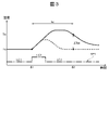
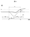
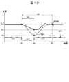
- FIG. 2 is a flow chart showing an example of processing executed by the vehicle control device 10 of FIG. 3 and 4 are graphs showing an example of temperature changes of the CPU 11 of FIG.
- the vehicle control device 10 When the vehicle control device 10 starts the processing shown in FIG. 2, it executes processing P1 for monitoring the load state of the CPU 11, for example.
- the CPU 11 detects, for example, the current value of the CPU 11 by means of the abnormality detection unit 112, and stores the time-series data of the current value in the memory 13 as the time change of the load state of the CPU 11 for monitoring.
- the CPU 11 may store a physical quantity other than the current value, such as the temperature detected by the temperature sensor 111 , in the memory 13 as the load state of the CPU 11 .
- the CPU 11 executes the standard pattern determination process P2, for example, by means of the abnormality detection unit 112 .
- the driver of the vehicle 1 inputs, for example, a request for advanced driving assistance or automatic driving to the vehicle control unit 113 of the vehicle control device 10 via the input device 4 by switch operation, voice, line of sight, or the like. Then, the CPU 11 causes the vehicle control unit 113 to execute vehicle control processing related to advanced driving assistance or automatic driving, for example.
- vehicle control processing includes, for example, at least one of constant speed automatic driving, preceding vehicle following, brake control, and lane keeping.
- the aforementioned vehicle control processing includes, for example, image processing calculations for the monocular camera and stereo camera included in the sensor 2. Further, the vehicle control device 10 performs a RAM check by means of the CPU 11, for example, when the vehicle 1 is started or stopped.
- RAM checks include, for example, full area RAM checks.
- a RAM check is, for example, a process of detecting a failure of the memory 13 .
- the standard pattern determination process P2 shown in FIG. compares with standard patterns SP1 and SP2 stored in the memory 13 in advance.
- the abnormality detection unit 112 determines that the actual temporal change in the load state of the CPU 11 is different from the standard patterns SP1 and SP2 (NO)
- the CPU 11 for example, the vehicle control unit 113 to execute the vehicle control process P3.
- the vehicle control device 10 for example, executes the above-described vehicle control process related to advanced driving assistance or automatic driving by means of the vehicle control unit 113 of the CPU 11.
- the vehicle control device 10 may perform a RAM check, for example, using the abnormality detection section 112 of the CPU 11.
- FIG. After that, the vehicle control device 10 terminates the processing flow shown in FIG. Further, the vehicle control device 10 repeatedly executes the processing flow shown in FIG. 2 at a predetermined cycle.
- the CPU 11 performs, for example, , a process P4 for acquiring the standard temperature Ts.
- the standard patterns SP1 and SP2 shown in FIGS. 3 and 4 show temporal changes in the current value of the CPU 11 as temporal changes in the load state of the CPU 11 .
- the abnormality detection unit 112 of the CPU 11 acquires the standard temperature Ts and the standby time tw of the CPU 11 stored in the memory 13, for example.
- This standard temperature Ts is the temperature of the normal CPU 11 at time S2 when the standby time tw has elapsed from time S1 when the load state of the normal CPU 11 is changed by the standard patterns SP1 and SP2 and the standard patterns SP1 and SP2 are started.
- the temperature changes of the normal CPU 11 are indicated by dashed lines, and the actual temperature changes of the CPU 11 are indicated by solid lines.
- the standard patterns SP1 and SP2 of the load state of the CPU 11 change from the first load state LC1 to the higher second load state LC2 as shown in FIG. It includes a returning, stepped first pattern SP1. Further, the standard patterns SP1 and SP2 of the load state of the CPU 11 are, for example, as shown in FIG. 2 patterns SP2 are included.
- the first load state LC1 of the CPU 11 is, for example, a state in which the CPU 11 is not executing travel control processing, RAM check, and image calculation processing.
- the second load state LC2 of the CPU 11 is, for example, a state in which the CPU 11 is executing at least one of running control processing, RAM check, and image calculation processing.
- the waiting time tw in the first pattern SP1 is, for example, in a state without the cooling mechanism 14, as shown in FIG. is set to the time it takes for the temperature to drop and stabilize.
- the standby time tw in the second pattern SP2 is set, for example, in a state without the cooling mechanism 14, as shown in FIG. It is set to the time until the temperature of the CPU 11 rises and stabilizes.
- the vehicle control device 10 executes, for example, the process P5 of acquiring the evaluation temperature Te by the abnormality detection unit 112 of the CPU 11 .
- the abnormality detection unit 112 acquires the temperature detected by the temperature sensor 111, for example, at the time S2 after the standby time tw has elapsed from the time S1 when the standard patterns SP1 and SP2 are started, and calculates the evaluation temperature. It is stored in the memory 13 as Te.
- the vehicle control device 10 executes, for example, a process P6 of calculating the temperature difference ⁇ Tse between the standard temperature Ts of the CPU 11 and the evaluation temperature Te by the abnormality detection unit 112 of the CPU 11, as shown in FIGS. do.
- the abnormality detection unit 112 stores the calculated temperature difference ⁇ Tse in the memory 13, for example.
- the vehicle control device 10 executes, for example, the abnormality determination process P7 shown in FIG.
- the abnormality detection unit 112 acquires the temperature difference ⁇ Tse and the normal temperature difference ⁇ Tn from the memory 13, and determines whether the temperature difference ⁇ Tse is equal to or less than the normal temperature difference ⁇ Tn.
- the CPU 11 determines that the CPU 11 is normal, and executes the vehicle control process P3 described above. .
- the abnormality detection unit 112 determines whether the CPU 11 is abnormal.
- the abnormality detection unit 112 executes, for example, a process P8 of determining abnormality.
- the vehicle control device 10 executes, for example, a process P9 of calculating the difference between the temperature difference ⁇ Tse and the normal temperature difference ⁇ Tn by using the abnormality detection unit 112 of the CPU 11 .
- the vehicle control device 10 causes the abnormality detection unit 112 of the CPU 11 to execute the process P10 of determining the limitation of the process by the CPU 11.
- FIG. 1 the abnormality detection unit 112 determines the limitation of the control by the CPU 11 based on the criteria shown in Table 1 below, for example.
- the criteria shown in Table 1, which are used by the abnormality detection unit 112 in this process P10, are stored in advance in the memory 13, for example. Specifically, in the example shown in Table 1, for example, when the difference between the temperature difference ⁇ Tse and the normal temperature difference ⁇ Tn is 10° C. or more and less than 20° C., the abnormality detection unit 112 performs the vehicle control process. Without limitation, the driver of the vehicle 1 is notified of an abnormality including abnormal heat generation of the CPU 11 via the notification device 5 .
- the abnormality detection unit 112 sequentially limits processing from low to high processing load according to an increase in the difference between the temperature difference ⁇ Tse and the normal temperature difference ⁇ Tn, for example. Specifically, for example, in response to an increase in the difference between the temperature difference ⁇ Tse and the normal temperature difference ⁇ Tn, the abnormality detection unit 112 performs vehicle control processing in the order of constant speed automatic driving, preceding vehicle following, brake control, and lane keeping. limit the
- the abnormality detection unit 112 stops all vehicle control processes. For example, when limiting or stopping all vehicle control processes, abnormality detection unit 112 sequentially notifies the driver of vehicle 1 of the vehicle control processes to be limited or stopped via notification device 5 . After that, in the vehicle control process P3, the vehicle control device 10 executes the vehicle control process that is not restricted by the abnormality detection unit 112, and ends the process flow shown in FIG.
- the vehicle control device 10 of this embodiment includes the memory 13, the CPU 11, the temperature sensor 111 incorporated in the CPU 11, and the cooling mechanism 14 for cooling the CPU 11, as described above.
- Memory 13 stores standard patterns SP1 and SP2, standby time tw, and standard temperature Ts as shown in FIGS. 3 and 4, and normal temperature difference ⁇ Tn as shown in FIG.
- Standard patterns SP1 and SP2 are temporal changes in the load state of the CPU 11 .
- the standby time tw is the time from the start of the standard patterns SP1 and SP2 until the abnormality detection unit 112 acquires the evaluation temperature Te.
- the standard temperature Ts is the temperature of the CPU 11 when the standby time tw has elapsed after changing the load state of the normal CPU 11 according to the standard patterns SP1 and SP2.
- the normal temperature difference ⁇ Tn is a temperature difference with respect to the standard temperature Ts when at least one of the CPU 11 and the cooling mechanism 14 is normal. Then, the CPU 11 stores the load state of the CPU 11 in the memory 13 and monitors it. Further, when the load state of the CPU 11 changes in the standard patterns SP1 and SP2, the CPU 11 determines the temperature difference ⁇ Tse between the evaluation temperature Te and the standard temperature Ts at the time point S2 when the standby time tw has elapsed from the start of the standard patterns SP1 and SP2. Calculate Then, the CPU 11 determines an abnormality when the temperature difference ⁇ Tse is larger than the normal temperature difference ⁇ Tn.
- the vehicle control device 10 of the present embodiment can determine an abnormality such as abnormal heat generation of the CPU 11 as described above without using a temperature sensor other than the temperature sensor 111 incorporated in the CPU 11. it becomes possible to Therefore, according to the vehicle control device 10 of the present embodiment, it is possible to detect abnormal heat generation of the CPU 11 while suppressing an increase in size, an increase in the number of parts, and an increase in cost.
- the standard patterns SP1 and SP2 include a first pattern SP1 as shown in FIG. 3 and a second pattern SP2 as shown in FIG.
- the first pattern SP1 is a pattern of changing from the first load state LC1 to the second higher load state LC2 and returning to the first load state LC1.
- the second pattern SP2 is a pattern that changes from the second load state LC2 to the first load state LC1 and then returns to the second load state LC2.
- the waiting time tw in the first pattern SP1 is set to the time until the temperature of the CPU 11 drops and stabilizes after the load state of the normal CPU 11 is changed in the first pattern SP1 without the cooling mechanism 14. ing.
- the standby time tw in the second pattern SP2 is set to the time until the temperature of the CPU 11 rises and stabilizes after the load state of the normal CPU 11 is changed in the second pattern SP2 without the cooling mechanism 14. ing. Then, the CPU 11 determines abnormal heat generation of the CPU 11 when the temperature difference ⁇ Tse is larger than the normal temperature difference ⁇ Tn.
- the abnormality determined based on the fact that the temperature difference ⁇ Tse is larger than the normal temperature difference ⁇ Tn is at least one of abnormal heat generation of the CPU 11 and heat radiation abnormality of the cooling mechanism 14. is included, abnormal heat generation of the CPU 11 can be determined.
- the CPU 11 executes a plurality of processes with different processing loads, and limits the processes according to the difference between the temperature difference ⁇ Tse and the normal temperature difference ⁇ Tn.
- the vehicle control device 10 of the present embodiment sequentially limits, for example, constant-speed automatic driving, preceding vehicle following, brake control, lane keeping, etc., thereby minimizing the processing to be limited. , the temperature rise of the CPU 11 can be suppressed, and the malfunction of the CPU 11 can be prevented.
- the memory 13 stores restrictions on the processing of the CPU 11 according to the difference between the temperature difference ⁇ Tse and the normal temperature difference ⁇ Tn as shown in Table 1 above. Further, the CPU 11 limits the processing of the CPU 11 according to the difference between the temperature difference ⁇ Tse and the normal temperature difference ⁇ Tn. With such a configuration, the vehicle control device 10 of the present embodiment can more effectively suppress the temperature rise of the CPU 11, prevent malfunction of the CPU 11 more reliably, and improve the safety of the vehicle 1. can be done.
- the CPU 11 notifies the restriction of the processing of the CPU 11 via the notification device 5 when restricting the processing of the CPU 11 .
- the vehicle control device 10 of the present embodiment can inform the driver of the vehicle 1 of the limitation or suspension of the vehicle control processing by the CPU 11, and can further improve the safety of the vehicle 1. .
- the second load state LC2 is a state in which the CPU 11 is executing RAM check or image calculation processing.
- the vehicle control device 10 of the present embodiment is configured so that the second load state LC2 includes abnormal heat generation of the CPU 11 or abnormal heat dissipation of the cooling mechanism 14 when the CPU 11 executes RAM check or image calculation processing. Anomalies can be detected.
- the first load state LC1 is a state in which the CPU 11 is not executing travel control processing, RAM check, and image calculation processing.
- the vehicle control device 10 of the present embodiment can detect abnormal heat generation of the CPU 11 or abnormal heat radiation of the cooling mechanism 14 when the CPU 11 executes at least one of the running control process, RAM check, and image calculation process. It is possible to detect anomalies including
- the vehicle control device 10 of this embodiment is not limited to the configuration described above.
- the CPU 12 includes the abnormality detection unit 112
- the CPU 12 can detect abnormalities including abnormal heat generation of the CPU 11 and abnormal heat dissipation of the cooling mechanism 14 .
- standard patterns SP1 and SP2 include a first pattern SP1 and a second pattern SP2, like the examples shown in FIGS. More specifically, the first pattern SP1 changes from a first load condition LC1 to a second higher load condition LC2 and back to the first load condition LC1. Also, the second pattern SP2 changes from the second load state LC2 to the first load state LC1 and returns to the second load state LC2.
- first pattern SP1 changes from a first load condition LC1 to a second higher load condition LC2 and back to the first load condition LC1.
- the second pattern SP2 changes from the second load state LC2 to the first load state LC1 and returns to the second load state LC2.
- the standby time tw in the first pattern SP1 is a state in which the normal CPU 11 can normally dissipate heat through the cooling mechanism 14, and the load state of the CPU 11 is changed in the first pattern SP1. It is set to the time until the temperature of the CPU 11 rises and reaches the maximum temperature Tmax.
- the standby time tw in the second pattern SP2 is the state in which the normal CPU 11 can normally dissipate heat through the cooling mechanism 14, and when the load state of the CPU 11 is changed in the second pattern SP2, the temperature of the CPU 11 is It is set to the time it takes for the temperature to drop and reach the minimum temperature Tmin.
- the memory 13 stores the maximum temperature Tmax described above as the standard temperature Ts when the time change of the load state of the CPU 11 is equivalent to the first pattern SP1 shown in FIG. Then, the CPU 11 acquires the temperature of the CPU 11 at time S2 when the first pattern SP1 changes from the second load state LC2 to the first load state LC1 as the evaluation temperature Te. Then, when the temperature difference ⁇ Tse between the evaluation temperature Te and the standard temperature Ts is larger than the normal temperature difference ⁇ Tn, the CPU 11 can determine abnormalities including abnormal heat generation of the CPU 11 and abnormal heat dissipation of the cooling mechanism 14 .
- the memory 13 stores the aforementioned minimum temperature Tmin as the standard temperature Ts when the time change of the load state of the CPU 11 is equivalent to the second pattern SP2 shown in FIG. Then, the CPU 11 acquires the temperature of the CPU 11 at time S2 when the second pattern SP2 changes from the first load state LC1 to the second load state LC2 as the evaluation temperature Te. Then, when the temperature difference ⁇ Tse between the evaluation temperature Te and the standard temperature Ts is larger than the normal temperature difference ⁇ Tn, the CPU 11 can determine abnormalities including abnormal heat generation of the CPU 11 and abnormal heat dissipation of the cooling mechanism 14 .
- a state in which the normal CPU 11 can normally dissipate heat through the cooling mechanism 14 means a state in which the cooling mechanism 14 is normally arranged with respect to the normal CPU 11 and can dissipate heat as designed.
- the state in which the cooling mechanism 14 cannot dissipate heat normally means that the CPU 11 cannot dissipate heat, for example, if the cooling mechanism 14 is improperly installed, causing some kind of trouble in the heat transfer path, or if the cooling fan breaks down. is impeded.
- standard patterns SP1 and SP2 include a first pattern SP1 and a second pattern SP2, like the examples shown in FIGS. More specifically, the first pattern SP1 changes from a first load condition LC1 to a second higher load condition LC2 and maintains that condition. Also, the second pattern SP2 changes from the second load state LC2 to the first load state LC1 and maintains that state.
- the standby time tw in the first pattern SP1 is a state in which the normal CPU 11 can normally dissipate heat through the cooling mechanism 14, and when the load state of the CPU 11 is changed in the first pattern SP1, the temperature of the CPU 11 rises.
- the standby time tw in the second pattern SP2 is a state in which the normal CPU 11 can normally dissipate heat through the cooling mechanism 14, and when the load state of the CPU 11 is changed in the second pattern SP2, the temperature of the CPU 11 decreases. is set to the time it takes for the
- the CPU 11 acquires the temperature of the CPU 11 at time S2 when the load state of the CPU 11 changes in the standard patterns SP1 and SP2 and the temperature of the CPU 11 stabilizes as the evaluation temperature Te.
- the memory 13 stores in advance the standard temperature Ts of the CPU 11 when the standby time tw has elapsed after changing the load state of the normal CPU 11 according to the standard patterns SP1 and SP2.
- the CPU 11 can determine an abnormality including abnormal heat generation of the CPU 11 or abnormal heat dissipation of the cooling mechanism 14 .
- the vehicle control device 10 of Modification 2 it is possible not only to obtain the same effect as the vehicle control device 10 of the above-described embodiment, but also to detect abnormal heat generation of the CPU 11 using simpler standard patterns SP1 and SP2. Abnormality including heat radiation abnormality of the cooling mechanism 14 can be determined.
- the second load state LC2 in the first pattern SP1 is, for example, a state in which the CPU 11 is executing a full-area RAM check or constant-speed automatic running control.
- the vehicle control device 10 can detect abnormal heat generation of the CPU 11 or abnormal heat radiation of the cooling mechanism 14 when the CPU 11 executes the full area RAM check or the constant speed automatic travel control.
- a second load state LC2 in the second pattern SP2 is, for example, a state in which the CPU 11 is executing vehicle control. Thereby, the vehicle control device 10 can detect abnormal heat generation of the CPU 11 or abnormal heat radiation of the cooling mechanism 14 when the CPU 11 executes vehicle control.
- standard patterns SP1 and SP2 include a first pattern SP1 and a second pattern SP2, like the examples shown in FIGS. More specifically, the first pattern SP1 changes from a first load condition LC1 to a second higher load condition LC2 and back to the first load condition LC1. Also, the second pattern SP2 changes from the second load state LC2 to the first load state LC1 and returns to the second load state LC2.
- the waiting time tw in the first pattern SP1 includes the first waiting time tw1 and the second waiting time tw2.
- the first standby time tw1 is the state in which the normal CPU 11 can normally dissipate heat through the cooling mechanism 14, and when the load state of the CPU 11 is changed according to the first pattern SP1, the temperature of the CPU 11 rises to reach the maximum temperature. is the time to reach
- the second waiting time tw2 is the time until the temperature of the CPU 11 rises and reaches the maximum temperature, and then the temperature of the CPU 11 drops and stabilizes when the load state of the CPU 11 is changed according to the first pattern SP1. .
- the waiting time tw in the second pattern SP2 includes a third waiting time tw3 and a fourth waiting time tw4.
- the third waiting time tw3 is the state in which the normal CPU 11 can normally dissipate heat through the cooling mechanism 14, and when the load state of the CPU 11 is changed according to the second pattern SP2, the temperature of the CPU 11 drops to the minimum temperature. is the time to reach
- the fourth standby time tw4 is the state in which the normal CPU 11 can normally dissipate heat via the cooling mechanism 14, and when the load state of the CPU 11 is changed according to the second pattern SP2, the temperature of the CPU 11 drops to the minimum temperature. is reached, and the temperature of the CPU 11 rises and stabilizes.
- the CPU 11 determines that the temperature difference ⁇ Tse1 between the standard temperature Ts1 and the evaluation temperature Te1 during the first waiting time tw1 is greater than the normal temperature difference ⁇ Tn1, and that the temperature difference ⁇ Tse2 during the second waiting time tw2 is the normal temperature difference. If the difference is equal to ⁇ Tn2 or smaller than the normal temperature difference ⁇ Tn2, abnormal heat generation of the CPU 11 is determined. Further, the CPU 11 determines if the temperature difference ⁇ Tse1 during the first waiting time tw1 is equal to or smaller than the normal temperature difference ⁇ Tn1 and the temperature difference ⁇ Tse2 during the second waiting time tw2 is greater than the normal temperature difference ⁇ Tn2. Then, the heat radiation abnormality of the cooling mechanism 14 is determined.
- the CPU 11 determines whether the temperature difference ⁇ Tse3 in the third waiting time tw3 is greater than the normal temperature difference ⁇ Tn3 and the temperature difference ⁇ Tse4 in the fourth waiting time tw4 is equal to the normal temperature difference ⁇ Tn4 or not. If the difference is smaller than ⁇ Tn4, abnormal heat generation of the CPU 11 is determined. Further, when the temperature difference ⁇ Tse3 in the third waiting time tw3 is equal to or smaller than the normal temperature difference ⁇ Tn3 and the temperature difference ⁇ Tse4 in the fourth waiting time tw4 is larger than the normal temperature difference ⁇ Tn4, the CPU 11 , the heat radiation abnormality of the cooling mechanism 14 is determined.
- abnormal heat generation of the CPU 11 and abnormal heat radiation of the cooling mechanism 14 can be determined.
- a controller 10 can be provided.
Landscapes
- Engineering & Computer Science (AREA)
- Automation & Control Theory (AREA)
- Mechanical Engineering (AREA)
- Human Computer Interaction (AREA)
- Transportation (AREA)
- Theoretical Computer Science (AREA)
- General Engineering & Computer Science (AREA)
- General Physics & Mathematics (AREA)
- Physics & Mathematics (AREA)
- Control Of Driving Devices And Active Controlling Of Vehicle (AREA)
- Cooling Or The Like Of Electrical Apparatus (AREA)
- Debugging And Monitoring (AREA)
- Safety Devices In Control Systems (AREA)
Abstract
本開示は、大型化、部品点数増加、コスト増加を抑制しつつ、CPUの異常発熱または冷却機構の放熱異常を検出することが可能な車両制御装置を提供する。本開示に係る車両制御装置は、メモリと、CPUと、CPUに内蔵された温度センサと、CPUを冷却する冷却機構と、を備えている。メモリは、標準パターンSP1と、待機時間twと、標準温度Tsと、正常温度差とが記憶されている。CPUは、CPUの負荷状態をメモリに記憶させて監視する。CPUは、負荷状態が標準パターンSP1で変化した場合に、第1パターンSP1の開始から待機時間twが経過した時点の温度センサの評価温度Teと、標準温度Tsとの温度差ΔTseを算出し、その温度差ΔTseが正常温度差よりも大きい場合に、異常を判定する。
Description
本開示は、車両制御装置に関する。
従来からCPU冷却機構に関する発明が知られている(下記特許文献1)。特許文献1に記載されたCPU冷却機構は、温度センサICをヒートシンクのフィンの近くに配置し、温度差特性を統計的に算出したデータを元に、実動作時の温度との比較により、冷却機構の異常を検出する。これにより、冷却機構において、冷却部材の物理的接触不良など、接触面を直に見ることができないために通常では発見できない不具合を検出できる(特許文献1、要約等)。
特許文献1に記載された冷却機構は、実動作時のCPU温度と温度センサIC温度との差をしきい値と比較することにより、CPUの冷却が正常に行われているかを検出することができる(第0013段落等)。しかしながら、この従来の冷却機構を車両制御装置に適用する場合には、CPUとは別に温度センサICが必要になるため、車両制御装置の大型化、部品点数の増加、コスト増加などが課題になる。
本開示は、大型化、部品点数増加、およびコスト増加を抑制しつつ、CPUの異常発熱または冷却機構の放熱異常を検出することが可能な車両制御装置を提供する。
本開示の一態様は、メモリと、CPUと、該CPUに内蔵された温度センサと、該CPUを冷却する冷却機構と、を備えた車両制御装置であって、前記メモリは、前記CPUの負荷状態の時間的な変化である標準パターンと、前記標準パターンの開始から前記温度センサで評価温度を取得するまでの待機時間と、正常な前記CPUの負荷状態を前記標準パターンで変化させて前記待機時間が経過した時点の前記CPUの標準温度と、前記CPUと前記冷却機構の少なくとも一方が正常である場合の前記標準温度に対する正常温度差と、が記憶され、前記CPUは、前記CPUの負荷状態を前記メモリに記憶させて監視し、前記CPUの負荷状態が前記標準パターンで変化した場合に、前記標準パターンの開始から前記待機時間が経過した時点の前記評価温度と、前記標準温度との温度差を算出し、前記温度差が前記正常温度差よりも大きい場合に、異常を判定することを特徴とする車両制御装置である。
本開示の上記一態様によれば、大型化、部品点数増加、コスト増加を抑制しつつ、CPUの異常発熱または冷却機構の放熱異常を検出することが可能な車両制御装置を提供することができる。
以下、図面を参照して本開示に係る車両制御装置の実施形態を説明する。図1は、本開示に係る車両制御装置の一実施形態を示すブロック図である。
本実施形態の車両制御装置10は、たとえば、車両1に搭載され、車両1の各部を制御する。車両1は、たとえば、ガソリンエンジン車、ディーゼルエンジン車、ハイブリッド車、電気自動車、および水素自動車などを含む。車両1は、たとえば、センサ2、アクチュエータ3、入力装置4、および報知装置5を備えている。車両1の他の一般的な構成については、図示および説明を省略する。
センサ2は、たとえば、外界センサと車両センサとを含む。外界センサは、たとえば、単眼カメラ、ステレオカメラ、レーザレーダ、ミリ波レーダ、赤外線センサ、超音波センサなどを含み、車両1の周囲の物体を検出する。車両センサは、たとえば、車輪速センサ、加速度センサ、角速度センサ、全球衛星測位システム(GNSS)の受信機、アクセルセンサ、ブレーキセンサ、操舵角センサなどを含み、車両1の速度、加速度、角速度、位置、アクセル操作量、ブレーキ操作量、操舵角などを検出する。
アクチュエータ3は、たとえば、車両制御装置10から入力される制御信号に基づいて、車両1のパワートレイン、ブレーキ装置、および操舵装置などを駆動させ、車両1の前進、後進、加速、減速、停止、および操舵を行う。
入力装置4は、たとえば、タッチパネル、操作ボタン、視線検出装置、音声認識装置、操作レバーなどを含む。入力装置4は、たとえば、車両1の運転者による操作および入力を受け付けて、運転者の操作および入力に応じた信号を車両制御装置10へ出力する。
報知装置5は、たとえば、表示装置、表示ランプ、スピーカ、ブザーなどを含む。報知装置5は、たとえば、車両制御装置10から入力される信号に基づいて、表示装置または表示ランプによる各種の表示や、スピーカまたはブザーから発する音声によって、運転者に対して、車両制御装置10の異常を含む各種の情報を報知する。
車両制御装置10は、たとえば、センサ2によって検出された各種の情報に基づいて、アクチュエータ3を制御することで、車両1の先進運転支援や自動運転を行う。車両制御装置10は、たとえば、中央処理装置(CPU)11,12と、メモリ13と、冷却機構14とを備えている。また、車両制御装置10は、たとえば、図示を省略する入出力部とタイマーと、各種のプログラムを備えている。
車両制御装置10は、たとえば、一つ以上のマイクロコンピュータまたはファームウェアによって構成することができる。また、図1に示す例において、車両制御装置10は、二つのCPU11,12を備えているが、少なくとも一つのCPU11を備えていればよい。また、CPU11がメモリを内蔵している場合には、車両制御装置10は、CPU11の外部のメモリ13を有しなくてもよい。
CPU11は、たとえば、温度センサ111と、異常検知部112と、車両制御部113とを備えている。温度センサ111は、たとえば、CPU11に内蔵された半導体温度センサである。温度センサ111は、たとえば、サーマルダイオードによって構成され、CPU11の温度を検出する。異常検知部112および車両制御部113は、たとえば、CPU11によってメモリ13に記憶されたプログラムを実行することによって実現されるCPU11の機能を表している。
異常検知部112は、たとえば、温度センサ111によって検出されたCPU11の温度に基づいて、異常を判定する。また、異常検知部112は、たとえば、異常を判定した場合に、報知装置5へ制御信号を出力して車両1の運転者に対して判定した異常を報知する。異常検知部112が判定する異常は、たとえば、CPU11の異常発熱と、冷却機構14の放熱異常とを含む。CPU11の異常発熱とは、たとえば、CPU11に何らかの異常が発生することで、正常なCPU11と比較して、CPU11の温度がより高温になった状態である。冷却機構14の放熱異常については後述する。
車両制御部113は、たとえば、センサ2によって検出された各種の情報に基づいて、アクチュエータ3を制御することで、車両1の先進運転支援や自動運転を行う。より具体的には、車両制御部113は、たとえば、アクチュエータ3を制御することで、定速自動走行、先行車追従、ブレーキ制御、またはレーンキープなどの制御を実行する。また、車両制御部113は、たとえば、異常検知部112によって異常が検知された場合に、実行する制御を制限する。
CPU12は、たとえば、CPU11と同様の構成を備えている。また、CPU12は、たとえば、CPU11の異常検知部112と車両制御部113を備えていてもよい。この場合、CPU11は、異常検知部112および車両制御部113を有しなくてもよい。また、前述のように、CPU11が図1のすべての構成を備える場合には、CPU12を省略することも可能である。
メモリ13は、たとえば、RAMによって構成されている。また、メモリ13は、RAMおよびROMを含んでもよい。メモリ13は、たとえば、異常検知部112および車両制御部113の機能を実現するための各種のプログラムが記憶されている。また、メモリ13は、たとえば、CPU11の負荷状態の時間的な変化である標準パターンSP1,SP2と、その標準パターンSP1,SP2の開始から温度センサ111によって評価温度Teを取得するまでの待機時間tw(図3、図4等)が記憶されている。
また、メモリ13は、たとえば、正常なCPU11の負荷状態を標準パターンSP1,SP2で変化させて待機時間twが経過した時点S2のCPU11の標準温度Tsと、CPU11および冷却機構14が正常である場合の標準温度Tsに対する正常温度差ΔTn(図3、図4等)が記憶されている。また、メモリ13は、たとえば、後述する表1に示すような温度差ΔTseと正常温度差ΔTnとの差の範囲に応じたCPU11の処理の制限が記憶されている。また、メモリ13は、たとえば、CPU11およびCPU12から入力された情報を記憶する。なお、CPU11がメモリを内蔵する場合には、メモリ13に記憶させる情報を、CPU11に内蔵されたメモリに記憶させてもよい。
冷却機構14は、たとえば、図示を省略する放熱シートと、ヒートシンクとを備えている。放熱シートは、たとえば、CPU11に接してCPU11の熱をヒートシンクへ伝達する。ヒートシンクは、たとえば、受熱板を介して放熱シートに接し、放熱シートから伝達されたCPU11の熱を、複数のフィンによって放熱する。冷却機構14は、フィンを空冷する冷却ファンや、受熱板の熱をフィンへ伝達するヒートパイプを備えてもよい。
冷却機構14は、CPU11に対して正常に設置されていれば、CPU11を効率よく冷却することが可能である。しかし、冷却機構14は、たとえば、不適切な設置によって熱の伝達経路に何らかの障害が発生したり、冷却ファンが故障したりすると、CPU11の放熱が阻害され、冷却機構14が正常である場合と比較してCPU11の温度が上昇しやすくなる。このような状態が、冷却機構14の放熱異常である。
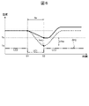
以下、図2から図10を参照して、本実施形態の車両制御装置10の処理について、詳細に説明する。図2は、図1の車両制御装置10が実行する処理の一例を示すフロー図である。図3および図4は、図1のCPU11の温度変化の一例を示すグラフである。
車両制御装置10は、図2に示す処理を開始すると、たとえば、CPU11の負荷状態を監視する処理P1を実行する。CPU11は、たとえば、異常検知部112により、CPU11の電流値を検出し、その電流値の時系列データを、CPU11の負荷状態の時間変化としてメモリ13に記憶させて監視する。なお、CPU11は、たとえば、温度センサ111によって検出した温度など、電流値以外の物理量をCPU11の負荷状態としてメモリ13に記憶させてもよい。次に、CPU11は、たとえば、異常検知部112により、標準パターンの判定処理P2を実行する。
車両1の運転者は、たとえば、高度運転支援または自動運転の要求を、スイッチ操作、音声、または視線などにより、入力装置4を介して車両制御装置10の車両制御部113へ入力する。すると、CPU11は、たとえば、車両制御部113により、高度運転支援または自動運転に係る車両制御処理を実行する。この車両制御処理は、たとえば、定速自動走行、先行車追従、ブレーキ制御、またはレーンキープの少なくとも一つを含む。CPU11が車両制御処理を開始すると、CPU11の処理負荷が増大して、CPU11の負荷状態が変化する。
前述の車両制御処理は、たとえば、センサ2に含まれる単眼カメラやステレオカメラの画像処理演算を含む。また、車両制御装置10は、たとえば、車両1の起動時や作動停止時などに、CPU11によってRAMチェックを実行する。RAMチェックは、たとえば、全領域RAMチェックを含む。RAMチェックは、たとえば、メモリ13の故障を検知する処理である。CPU11が画像処理演算やRAMチェックを実行すると、CPU11の処理負荷が増大して、CPU11の負荷状態が変化する。
図2に示す標準パターンの判定処理P2において、CPU11は、たとえば、異常検知部112により、メモリ13に記憶させた実際のCPU11の負荷状態の時間的な変化と、図3および図4に示すように、メモリ13にあらかじめ記憶された標準パターンSP1,SP2とを比較する。この処理P2において、異常検知部112が、たとえば、実際のCPU11の負荷状態の時間的な変化と、標準パターンSP1,SP2とが異なる(NO)と判定すると、CPU11は、たとえば、車両制御部113による車両制御処理P3を実行する。
この処理P3において、車両制御装置10は、たとえば、CPU11の車両制御部113により、前述の高度運転支援または自動運転に係る車両制御処理を実行する。なお、この処理P3において、車両制御装置10は、たとえば、CPU11の異常検知部112により、RAMチェックを実行してもよい。その後、車両制御装置10は、図2に示す処理フローを終了する。また、車両制御装置10は、図2に示す処理フローを、所定の周期で繰り返し実行する。
一方、前述の標準パターンの判定処理P2において、異常検知部112が、CPU11の負荷状態の時間的な変化と、標準パターンSP1,SP2とが同等である(YES)と判定すると、CPU11は、たとえば、標準温度Tsを取得する処理P4を実行する。なお、図3、図4に示す標準パターンSP1,SP2は、CPU11の負荷状態の時間的な変化として、CPU11の電流値の時間的な変化を示している。
図3、図4に示す例において、CPU11の異常検知部112は、たとえば、メモリ13に記憶されたCPU11の標準温度Tsおよび待機時間twを取得する。この標準温度Tsは、正常なCPU11の負荷状態を標準パターンSP1,SP2で変化させ、標準パターンSP1,SP2が開始された時点S1から待機時間twが経過した時点S2の正常なCPU11の温度である。なお、図3、図4では、正常なCPU11の温度変化を、それぞれ破線で示し、実際のCPU11の温度変化を実線で示している。
より具体的には、CPU11の負荷状態の標準パターンSP1,SP2は、たとえば、図3に示すように、第1負荷状態LC1からより高い第2負荷状態LC2へ変化して第1負荷状態LC1に戻る、ステップ状の第1パターンSP1を含む。また、CPU11の負荷状態の標準パターンSP1,SP2は、たとえば、図4に示すように、第2負荷状態LC2から第1負荷状態LC1へ変化して第2負荷状態LC2に戻る、ステップ状の第2パターンSP2を含む。
ここで、CPU11の第1負荷状態LC1は、たとえば、CPU11が走行制御処理、RAMチェック、および画像演算処理を実行していない状態である。また、CPU11の第2負荷状態LC2は、たとえば、CPU11が走行制御処理、RAMチェック、または画像演算処理の少なくとも一つを実行している状態である。
第1パターンSP1における待機時間twは、たとえば、冷却機構14がない状態で、図3に示すように、正常なCPU11の負荷状態を第1パターンSP1で変化させた後に、破線で示す正常なCPU11の温度が低下して安定するまでの時間に設定されている。また、第2パターンSP2における待機時間twは、たとえば、冷却機構14がない状態で、図4に示すように、正常なCPUの負荷状態を第2パターンSP2で変化させた後に、破線で示す正常なCPU11の温度が上昇して安定するまでの時間に設定されている。
次に、車両制御装置10は、たとえば、CPU11の異常検知部112によって、評価温度Teを取得する処理P5を実行する。この処理P5において、異常検知部112は、たとえば、標準パターンSP1,SP2が開始された時点S1から待機時間twが経過した時点S2において、温度センサ111によって検出された温度を取得して、評価温度Teとしてメモリ13に記憶させる。
次に、車両制御装置10は、たとえば、CPU11の異常検知部112によって、図3、図4に示すように、CPU11の標準温度Tsと評価温度Teとの温度差ΔTseを算出する処理P6を実行する。この処理P6において、異常検知部112は、たとえば、算出した温度差ΔTseをメモリ13に記憶させる。
次に、車両制御装置10は、たとえば、CPU11の異常検知部112によって、図2に示す異常判定処理P7を実行する。この処理P7において、異常検知部112は、たとえば、メモリ13から温度差ΔTseと正常温度差ΔTnを取得して、温度差ΔTseが正常温度差ΔTn以下であるか否かを判定する。この処理P7において、異常検知部112が、温度差ΔTseは正常温度差ΔTn以下である(YES)と判定すると、CPU11は、CPU11が正常であると判断し、前述の車両制御処理P3を実行する。
一方、異常判定処理P7において、異常検知部112が、温度差ΔTseは正常温度差ΔTn以下ではない(NO)、すなわち、温度差ΔTseは正常温度差ΔTnよりも大きい、と判定すると、異常検知部112は、CPU11の異常を判定する。次に、異常検知部112は、たとえば、異常を判別する処理P8を実行する。
この処理P8において、CPU11の異常検知部112は、異常の原因がCPU11の異常発熱であるか、または、冷却機構14の放熱異常であるかを判別する。この処理P8において、CPU11の負荷状態の時間変化が、図3に示す第1パターンSP1または図4に示す第2パターンSP2と同等である場合、異常検知部112は、前述の異常判定処理P7で判定した異常が、CPU11の異常発熱であることを判別する。
次に、車両制御装置10は、たとえば、CPU11の異常検知部112により、温度差ΔTseと正常温度差ΔTnとの差を算出する処理P9を実行する。次に、車両制御装置10は、たとえば、CPU11の異常検知部112により、CPU11による処理の制限を決定する処理P10を実行する。この処理P10において、異常検知部112は、たとえば、以下の表1に示すような判定基準に基づいて、CPU11による制御の制限を決定する。

この処理P10において異常検知部112が使用する表1に示すような判定基準は、たとえば、メモリ13にあらかじめ記憶されている。具体的には、表1に示す例において、異常検知部112は、たとえば、温度差ΔTseと正常温度差ΔTnとの差が10[℃]以上かつ20[℃]未満の場合、車両制御処理を制限せず、車両1の運転者に対し、報知装置5を介してCPU11の異常発熱を含む異常を報知する。
また、異常検知部112は、たとえば、温度差ΔTseと正常温度差ΔTnとの差の増加に応じて、処理負荷の低いものから高いものへ、順次、処理を制限していく。具体的には、異常検知部112は、たとえば、温度差ΔTseと正常温度差ΔTnとの差の増加に応じて、定速自動走行、先行車追従、ブレーキ制御、レーンキープの順に、車両制御処理を制限していく。
また、異常検知部112は、たとえば、温度差ΔTseと正常温度差ΔTnとの差が40[℃]以上になると、すべての車両制御処理を停止する。また、異常検知部112は、たとえば、車両制御処理を制限またはすべて停止する場合、車両1の運転者に対し、逐次、報知装置5を介して制限または停止される車両制御処理を報知する。その後、車両制御装置10は、車両制御処理P3において、異常検知部112によって制限されていない車両制御処理を実行し、図2に示す処理フローを終了する。
以下、本実施形態の車両制御装置10の作用を説明する。
本実施形態の車両制御装置10は、前述のように、メモリ13と、CPU11と、そのCPU11に内蔵された温度センサ111と、CPU11を冷却する冷却機構14と、を備えている。メモリ13は、たとえば図3および図4に示すような標準パターンSP1,SP2、待機時間tw、および標準温度Tsと、図2に示すような正常温度差ΔTnとが記憶されている。標準パターンSP1,SP2は、CPU11の負荷状態の時間的な変化である。待機時間twは、標準パターンSP1,SP2の開始から異常検知部112で評価温度Teを取得するまで時間である。標準温度Tsは、正常なCPU11の負荷状態を標準パターンSP1,SP2で変化させて待機時間twが経過した時点のCPU11の温度である。正常温度差ΔTnは、CPU11と冷却機構14の少なくとも一方が正常である場合の標準温度Tsに対する温度差である。そして、CPU11は、CPU11の負荷状態をメモリ13に記憶させて監視する。さらに、CPU11は、CPU11の負荷状態が標準パターンSP1,SP2で変化した場合に、標準パターンSP1,SP2の開始から待機時間twが経過した時点S2の評価温度Teと標準温度Tsとの温度差ΔTseを算出する。そして、CPU11は、温度差ΔTseが正常温度差ΔTnよりも大きい場合に、異常を判定する。
このような構成により、本実施形態の車両制御装置10は、CPU11に内蔵されている温度センサ111の他に温度センサを用いることなく、前述のように、たとえばCPU11の異常発熱などの異常を判定することが可能になる。したがって、本実施形態の車両制御装置10によれば、大型化、部品点数増加、およびコスト増加を抑制しつつ、CPU11の異常発熱を検出することが可能になる。
また、本実施形態の車両制御装置10において、標準パターンSP1,SP2は、図3に示すような第1パターンSP1と、図4に示すような第2パターンSP2とを含む。第1パターンSP1は、第1負荷状態LC1からより高い第2負荷状態LC2へ変化して第1負荷状態LC1に戻るパターンである。第2パターンSP2は、第2負荷状態LC2から第1負荷状態LC1へ変化して第2負荷状態LC2に戻るパターンである。また、第1パターンSP1における待機時間twは、冷却機構14がない状態で正常なCPU11の負荷状態を第1パターンSP1で変化させた後にCPU11の温度が低下して安定するまでの時間に設定されている。また、第2パターンSP2における待機時間twは、冷却機構14がない状態で正常なCPU11の負荷状態を第2パターンSP2で変化させた後にCPU11の温度が上昇して安定するまでの時間に設定されている。そして、CPU11は、温度差ΔTseが正常温度差ΔTnよりも大きい場合に、CPU11の異常発熱を判定する。
このような構成により、本実施形態の車両制御装置10は、温度差ΔTseが正常温度差ΔTnよりも大きいことに基づいて判定した異常が、CPU11の異常発熱と冷却機構14の放熱異常の少なくとも一方を含む場合に、CPU11の異常発熱を判別することができる。
また、本実施形態の車両制御装置10において、CPU11は、処理負荷の異なる複数の処理を実行し、温度差ΔTseと正常温度差ΔTnとの差に応じて処理を制限する。このような構成により、本実施形態の車両制御装置10は、たとえば、定速自動走行、先行車追従、ブレーキ制御、レーンキープなどを、順次、制限することで、制限する処理を最小限にしつつ、CPU11の温度上昇を抑制して、CPU11の誤作動を防止することができる。
また、本実施形態の車両制御装置10において、メモリ13は、前述の表1に示すような温度差ΔTseと正常温度差ΔTnとの差に応じたCPU11の処理の制限が記憶されている。また、CPU11は、温度差ΔTseと正常温度差ΔTnとの差に応じてCPU11の処理を制限する。このような構成により、本実施形態の車両制御装置10は、CPU11の温度上昇をより効果的に抑制して、CPU11の誤作動をより確実に防止して、車両1の安全性を向上させることができる。
また、本実施形態の車両制御装置10において、CPU11は、CPU11の処理を制限する場合に、報知装置5を介してCPU11の処理の制限を報知する。このような構成により、本実施形態の車両制御装置10は、CPU11による車両制御処理の制限や停止を、車両1の運転者に知らせることができ、車両1の安全性をより向上させることができる。
また、本実施形態の車両制御装置10において、第2負荷状態LC2は、CPU11がRAMチェックまたは画像演算処理を実行している状態である。このような構成により、本実施形態の車両制御装置10は、第2負荷状態LC2は、CPU11がRAMチェックまたは画像演算処理を実行する際に、CPU11の異常発熱または冷却機構14の放熱異常を含む異常を検知することができる。
また、本実施形態の車両制御装置10において、第1負荷状態LC1は、CPU11が走行制御処理、RAMチェック、および画像演算処理を実行していない状態である。このような構成により、本実施形態の車両制御装置10は、CPU11が走行制御処理、RAMチェック、または画像演算処理の少なくとも一つを実行する際に、CPU11の異常発熱または冷却機構14の放熱異常を含む異常を検知することができる。
なお、本実施形態の車両制御装置10は、前述の構成に限定されない。たとえば、CPU12が異常検知部112を備える場合、CPU12によってCPU11の異常発熱または冷却機構14の放熱異常を含む異常を検知することができる。以下、前述の実施形態に係る車両制御装置10のいくつかの変形例を説明する。
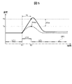
図5および図6は、車両制御装置10の変形例1に係るCPU11の温度変化を示すグラフである。図5および図6に示す例において、標準パターンSP1,SP2は、図3および図4に示す例と同様に、第1パターンSP1と第2パターンSP2とを含む。より具体的には、第1パターンSP1は、第1負荷状態LC1からより高い第2負荷状態LC2へ変化して第1負荷状態LC1に戻る。また、第2パターンSP2は、第2負荷状態LC2から第1負荷状態LC1へ変化して第2負荷状態LC2に戻る。一方、図5に示す例において、第1パターンSP1における待機時間twは、正常なCPU11が冷却機構14を介して正常に放熱可能な状態で、CPU11の負荷状態を第1パターンSP1で変化させたときに、CPU11の温度が上昇して最高温度Tmaxに達するまでの時間に設定されている。また、第2パターンSP2における待機時間twは、正常なCPU11が冷却機構14を介して正常に放熱可能な状態で、CPU11の負荷状態を第2パターンSP2で変化させたときに、CPU11の温度が低下して最低温度Tminに達するまでの時間に設定されている。
この変形例1において、メモリ13は、CPU11の負荷状態の時間変化が図5に示す第1パターンSP1と同等である場合の標準温度Tsとして、前述の最高温度Tmaxが記憶されている。そして、CPU11は、評価温度Teとして、第1パターンSP1が第2負荷状態LC2から第1負荷状態LC1へ変化した時点S2のCPU11の温度を取得する。そして、CPU11は、評価温度Teと標準温度Tsとの温度差ΔTseが、正常温度差ΔTnよりも大きい場合に、CPU11の異常発熱または冷却機構14の放熱異常を含む異常を判定することができる。
また、この変形例1において、メモリ13は、CPU11の負荷状態の時間変化が図6に示す第2パターンSP2と同等である場合の標準温度Tsとして、前述の最低温度Tminが記憶されている。そして、CPU11は、評価温度Teとして、第2パターンSP2が第1負荷状態LC1から第2負荷状態LC2へ変化した時点S2のCPU11の温度を取得する。そして、CPU11は、評価温度Teと標準温度Tsとの温度差ΔTseが、正常温度差ΔTnよりも大きい場合に、CPU11の異常発熱または冷却機構14の放熱異常を含む異常を判定することができる。
したがって、図5および図6に示す変形例1の車両制御装置10によれば、前述の実施形態に係る車両制御装置10と同様に異常を判定することができるだけでなく、より短時間に異常を判定することが可能になる。なお、正常なCPU11が冷却機構14を介して正常に放熱可能な状態とは、冷却機構14が正常なCPU11に対して正常に配置され、設計された通りに放熱可能な状態を意味する。換言すると、冷却機構14が正常に放熱可能でない状態は、たとえば、冷却機構14の不適切な設置によって熱の伝達経路に何らかの障害が発生したり、冷却ファンが故障したりするなど、CPU11の放熱が阻害されている状態である。
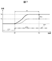
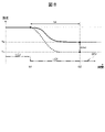
図7および図8は、車両制御装置10の変形例2に係るCPU11の温度変化を示すグラフである。図7および図8に示す例において、標準パターンSP1,SP2は、図3および図4に示す例と同様に、第1パターンSP1と第2パターンSP2とを含む。より具体的には、第1パターンSP1は、第1負荷状態LC1からより高い第2負荷状態LC2へ変化して、その状態を維持する。また、第2パターンSP2は、第2負荷状態LC2から第1負荷状態LC1へ変化して、その状態を維持する。第1パターンSP1における待機時間twは、正常なCPU11が冷却機構14を介して正常に放熱可能な状態で、CPU11の負荷状態を第1パターンSP1で変化させたときに、CPU11の温度が上昇して安定するまでの時間に設定されている。第2パターンSP2における待機時間twは、正常なCPU11が冷却機構14を介して正常に放熱可能な状態で、CPU11の負荷状態を第2パターンSP2で変化させたときに、CPU11の温度が低下して安定するまでの時間に設定されている。
この変形例2において、CPU11は、評価温度Teとして、CPU11の負荷状態が標準パターンSP1,SP2で変化して、CPU11の温度が安定する時点S2のCPU11の温度を取得する。また、メモリ13には、正常なCPU11の負荷状態を標準パターンSP1,SP2で変化させて待機時間twが経過した時点のCPU11の標準温度Tsがあらかじめ記憶されている。CPU11は、評価温度Teと標準温度Tsとの温度差ΔTseが、正常温度差ΔTnよりも大きい場合に、CPU11の異常発熱または冷却機構14の放熱異常を含む異常を判定することができる。この変形例2の車両制御装置10によれば、前述の実施形態の車両制御装置10と同様の効果を奏することができるだけでなく、より単純な標準パターンSP1,SP2を使用してCPU11の異常発熱や冷却機構14の放熱異常を含む異常を判定することができる。
この変形例2において、第1パターンSP1における第2負荷状態LC2は、たとえば、CPU11が全領域RAMチェックまたは定速自動走行制御を実行している状態である。これにより、車両制御装置10は、CPU11による全領域RAMチェックまたは定速自動走行制御の実行時にCPU11の異常発熱または冷却機構14の放熱異常を検知することができる。また、第2パターンSP2における第2負荷状態LC2は、たとえば、CPU11が車両制御を実行している状態である。これにより、車両制御装置10は、CPU11による車両制御の実行時にCPU11の異常発熱または冷却機構14の放熱異常を検知することができる。
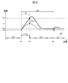
図9および図10は、車両制御装置10の変形例3に係るCPU11の温度変化を示すグラフである。図9および図10に示す例において、標準パターンSP1,SP2は、図3および図4に示す例と同様に、第1パターンSP1と第2パターンSP2とを含む。より具体的には、第1パターンSP1は、第1負荷状態LC1からより高い第2負荷状態LC2へ変化して第1負荷状態LC1に戻る。また、第2パターンSP2は、第2負荷状態LC2から第1負荷状態LC1へ変化して第2負荷状態LC2に戻る。
この変形例3では、第1パターンSP1における待機時間twは、第1待機時間tw1と第2待機時間tw2とを含む。第1待機時間tw1は、正常なCPU11が冷却機構14を介して正常に放熱可能な状態で、CPU11の負荷状態を第1パターンSP1で変化させたときに、CPU11の温度が上昇して最高温度に達するまでの時間である。第2待機時間tw2は、CPU11の負荷状態を第1パターンSP1で変化させたときに、CPU11の温度が上昇して最高温度に達し、さらにCPU11の温度が低下して安定するまでの時間である。
また、この変形例3では、第2パターンSP2における待機時間twは、第3待機時間tw3と第4待機時間tw4とを含む。第3待機時間tw3は、正常なCPU11が冷却機構14を介して正常に放熱可能な状態で、CPU11の負荷状態を第2パターンSP2で変化させたときに、CPU11の温度が低下して最低温度に達するまでの時間である。第4待機時間tw4は、正常なCPU11が冷却機構14を介して正常に放熱可能な状態で、CPU11の負荷状態を第2パターンSP2で変化させたときに、CPU11の温度が低下して最低温度に達し、さらにCPU11の温度が上昇して安定するまでの時間である。
この変形例3では、CPU11は、第1待機時間tw1における標準温度Ts1と評価温度Te1の温度差ΔTse1が正常温度差ΔTn1よりも大きく、かつ、第2待機時間tw2における温度差ΔTse2が正常温度差ΔTn2と等しいか正常温度差ΔTn2よりも小さい場合に、CPU11の異常発熱を判定する。さらに、CPU11は、第1待機時間tw1における温度差ΔTse1が正常温度差ΔTn1と等しいか正常温度差ΔTn1よりも小さく、かつ、第2待機時間tw2における温度差ΔTse2が正常温度差ΔTn2よりも大きい場合に、冷却機構14の放熱異常を判定する。
また、この変形例3では、CPU11は、第3待機時間tw3における温度差ΔTse3が正常温度差ΔTn3よりも大きく、かつ、第4待機時間tw4における温度差ΔTse4が正常温度差ΔTn4と等しいか正常温度差ΔTn4よりも小さい場合に、CPU11の異常発熱を判定する。さらに、CPU11は、第3待機時間tw3における温度差ΔTse3が正常温度差ΔTn3と等しいか温度差ΔTse3よりも小さく、かつ、第4待機時間tw4における温度差ΔTse4が正常温度差ΔTn4よりも大きい場合に、冷却機構14の放熱異常を判定する。
この変形例3の車両制御装置10によれば、前述の実施形態に係る車両制御装置10と同様に、CPU11の異常発熱と冷却機構14の放熱異常を判別することができる。以上説明したように、本実施形態およびその変形例によれば、大型化、部品点数増加、コスト増加を抑制しつつ、CPU11の異常発熱または冷却機構14の放熱異常を検出することが可能な車両制御装置10を提供することができる。
以上、図面を用いて本開示に係る車両制御装置の実施形態を詳述してきたが、具体的な構成はこの実施形態に限定されるものではなく、本開示の要旨を逸脱しない範囲における設計変更等があっても、それらは本開示に含まれるものである。
5 報知装置
10 車両制御装置
11 CPU
111 温度センサ
13 メモリ
14 冷却機構
LC1 第1負荷状態
LC2 第2負荷状態
SP1 第1パターン(標準パターン)
SP2 第2パターン(標準パターン)
Te 評価温度
Ts 標準温度
tw 待機時間
tw1 第1待機時間
tw2 第2待機時間
tw3 第3待機時間
tw4 第4待機時間
ΔTn 正常温度差
ΔTn1 正常温度差
ΔTn2 正常温度差
ΔTn3 正常温度差
ΔTn4 正常温度差
ΔTse 温度差
ΔTse1 温度差
ΔTse2 温度差
ΔTse3 温度差
ΔTse4 温度差
10 車両制御装置
11 CPU
111 温度センサ
13 メモリ
14 冷却機構
LC1 第1負荷状態
LC2 第2負荷状態
SP1 第1パターン(標準パターン)
SP2 第2パターン(標準パターン)
Te 評価温度
Ts 標準温度
tw 待機時間
tw1 第1待機時間
tw2 第2待機時間
tw3 第3待機時間
tw4 第4待機時間
ΔTn 正常温度差
ΔTn1 正常温度差
ΔTn2 正常温度差
ΔTn3 正常温度差
ΔTn4 正常温度差
ΔTse 温度差
ΔTse1 温度差
ΔTse2 温度差
ΔTse3 温度差
ΔTse4 温度差
Claims (12)
- メモリと、CPUと、該CPUに内蔵された温度センサと、該CPUを冷却する冷却機構と、を備えた車両制御装置であって、
前記メモリは、
前記CPUの負荷状態の時間的な変化である標準パターンと、
前記標準パターンの開始から前記温度センサで評価温度を取得するまでの待機時間と、 正常な前記CPUの負荷状態を前記標準パターンで変化させて前記待機時間が経過した時点の前記CPUの標準温度と、
前記CPUと前記冷却機構の少なくとも一方が正常である場合の前記標準温度に対する正常温度差と、
が記憶され、
前記CPUは、
前記CPUの負荷状態を前記メモリに記憶させて監視し、
前記CPUの負荷状態が前記標準パターンで変化した場合に、前記標準パターンの開始から前記待機時間が経過した時点の前記評価温度と前記標準温度との温度差を算出し、
前記温度差が前記正常温度差よりも大きい場合に、異常を判定することを特徴とする車両制御装置。 - 前記標準パターンは、第1負荷状態からより高い第2負荷状態へ変化して前記第1負荷状態に戻る第1パターンと、前記第2負荷状態から前記第1負荷状態へ変化して前記第2負荷状態に戻る第2パターンと、を含み、
前記第1パターンにおける前記待機時間は、前記冷却機構がない状態で正常な前記CPUの負荷状態を前記第1パターンで変化させた後に前記CPUの温度が低下して安定するまでの時間に設定され、
前記第2パターンにおける前記待機時間は、前記冷却機構がない状態で正常な前記CPUの負荷状態を前記第2パターンで変化させた後に前記CPUの温度が上昇して安定するまでの時間に設定され、
前記CPUは、前記温度差が前記正常温度差よりも大きい場合に、前記CPUの異常発熱を判定することを特徴とする請求項1に記載の車両制御装置。 - 前記標準パターンは、第1負荷状態からより高い第2負荷状態へ変化して前記第1負荷状態に戻る第1パターンと、前記第2負荷状態から前記第1負荷状態へ変化して前記第2負荷状態に戻る第2パターンと、を含み、
前記第1パターンにおける前記待機時間は、正常な前記CPUが前記冷却機構を介して正常に放熱可能な状態で、前記CPUの負荷状態を前記第1パターンで変化させたときに、前記CPUの温度が上昇して最高温度に達するまでの時間に設定され、
前記第2パターンにおける前記待機時間は、正常な前記CPUが前記冷却機構を介して正常に放熱可能な状態で、前記CPUの負荷状態を前記第2パターンで変化させたときに、前記CPUの温度が低下して最低温度に達するまでの時間に設定されていることを特徴とする請求項1に記載の車両制御装置。 - 前記標準パターンは、第1負荷状態からより高い第2負荷状態へ変化する第1パターンと、前記第2負荷状態から前記第1負荷状態へ変化する第2パターンと、を含み、
前記第1パターンにおける前記待機時間は、正常な前記CPUが前記冷却機構を介して正常に放熱可能な状態で、前記CPUの負荷状態を前記第1パターンで変化させたときに、前記CPUの温度が上昇して安定するまでの時間に設定され、
前記第2パターンにおける前記待機時間は、正常な前記CPUが前記冷却機構を介して正常に放熱可能な状態で、前記CPUの負荷状態を前記第2パターンで変化させたときに、前記CPUの温度が低下して安定するまでの時間に設定されていることを特徴とする請求項1に記載の車両制御装置。 - 前記標準パターンは、第1負荷状態からより高い第2負荷状態へ変化して前記第1負荷状態に戻る第1パターンと、前記第2負荷状態から前記第1負荷状態へ変化して前記第2負荷状態に戻る第2パターンと、を含み、
前記第1パターンにおける前記待機時間は、正常な前記CPUが前記冷却機構を介して正常に放熱可能な状態で、前記CPUの負荷状態を前記第1パターンで変化させたときに、前記CPUの温度が上昇して最高温度に達するまでの第1待機時間と、前記CPUの温度が低下して安定するまでの第2待機時間と、を含み、
前記第2パターンにおける前記待機時間は、正常な前記CPUが前記冷却機構を介して正常に放熱可能な状態で、前記CPUの負荷状態を前記第2パターンで変化させたときに、前記CPUの温度が低下して最低温度に達するまでの第3待機時間と、前記CPUの温度が上昇して安定するまでの第4待機時間と、を含み、
前記CPUは、
前記第1待機時間における前記温度差が前記正常温度差よりも大きく、かつ、前記第2待機時間における前記温度差が前記正常温度差と等しいか前記正常温度差よりも小さい場合に、前記CPUの異常発熱を判定し、
前記第1待機時間における前記温度差が前記正常温度差と等しいか前記正常温度差よりも小さく、かつ、前記第2待機時間における前記温度差が前記正常温度差よりも大きい場合に、前記冷却機構の放熱異常を判定し、
前記第3待機時間における前記温度差が前記正常温度差よりも大きく、かつ、前記第4待機時間における前記温度差が前記正常温度差と等しいか前記正常温度差よりも小さい場合に、前記CPUの異常発熱を判定し、
前記第3待機時間における前記温度差が前記正常温度差と等しいか前記正常温度差よりも小さく、かつ、前記第4待機時間における前記温度差が前記正常温度差よりも大きい場合に、前記冷却機構の放熱異常を判定することを特徴とする請求項1に記載の車両制御装置。 - 前記CPUは、処理負荷の異なる複数の処理を実行し、前記温度差と前記正常温度差との差に応じて前記処理を制限することを特徴とする請求項1に記載の車両制御装置。
- 前記メモリは、前記温度差と前記正常温度差との差に応じた前記CPUの処理の制限が記憶され、
前記CPUは、前記温度差と前記正常温度差との差に応じて前記処理を制限することを特徴とする請求項6に記載の車両制御装置。 - 前記CPUは、前記処理を制限する場合に、報知装置を介して前記処理の制限を報知することを特徴とする請求項7に記載の車両制御装置。
- 前記第2負荷状態は、前記CPUがRAMチェックまたは画像演算処理を実行している状態であることを特徴とする請求項2から請求項5のいずれか一項に記載の車両制御装置。
- 前記第1負荷状態は、前記CPUが走行制御処理、RAMチェック、および画像演算処理を実行していない状態であることを特徴とする請求項2から請求項5のいずれか一項に記載の車両制御装置。
- 前記第1パターンにおける前記第2負荷状態は、前記CPUが全領域RAMチェックまたは定速自動走行制御を実行している状態であることを特徴とする請求項4に記載の車両制御装置。
- 前記第2パターンにおける前記第2負荷状態は、前記CPUが車両制御を実行している状態であることを特徴とする請求項4に記載の車両制御装置。
Priority Applications (2)
| Application Number | Priority Date | Filing Date | Title |
|---|---|---|---|
| DE112021005090.7T DE112021005090T5 (de) | 2021-01-27 | 2021-09-07 | Fahrzeugsteuerungsvorrichtung |
| US18/253,952 US12503068B2 (en) | 2021-01-27 | 2021-09-07 | Vehicle control device |
Applications Claiming Priority (2)
| Application Number | Priority Date | Filing Date | Title |
|---|---|---|---|
| JP2021011236A JP7601650B2 (ja) | 2021-01-27 | 2021-01-27 | 車両制御装置 |
| JP2021-011236 | 2021-01-27 |
Publications (1)
| Publication Number | Publication Date |
|---|---|
| WO2022162997A1 true WO2022162997A1 (ja) | 2022-08-04 |
Family
ID=82654350
Family Applications (1)
| Application Number | Title | Priority Date | Filing Date |
|---|---|---|---|
| PCT/JP2021/032907 Ceased WO2022162997A1 (ja) | 2021-01-27 | 2021-09-07 | 車両制御装置 |
Country Status (4)
| Country | Link |
|---|---|
| US (1) | US12503068B2 (ja) |
| JP (1) | JP7601650B2 (ja) |
| DE (1) | DE112021005090T5 (ja) |
| WO (1) | WO2022162997A1 (ja) |
Families Citing this family (4)
| Publication number | Priority date | Publication date | Assignee | Title |
|---|---|---|---|---|
| US20230305608A1 (en) * | 2022-03-23 | 2023-09-28 | Microsoft Technology Licensing, Llc | Device-internal climate control for hardware preservation |
| JP7683973B1 (ja) * | 2024-03-07 | 2025-05-27 | Necプラットフォームズ株式会社 | 温度監視装置、温度監視方法および温度監視プログラム |
| CN118790180B (zh) * | 2024-09-13 | 2025-01-07 | 中国第一汽车股份有限公司 | 智能驾驶硬件设备调控方法、装置、电子设备及存储介质 |
| US20260103046A1 (en) * | 2024-10-16 | 2026-04-16 | Qualcomm Incorporated | System to ensure smooth on-chip operation during automotive cooling pump malfunction |
Citations (3)
| Publication number | Priority date | Publication date | Assignee | Title |
|---|---|---|---|---|
| JP2013168107A (ja) * | 2012-02-17 | 2013-08-29 | Nec Computertechno Ltd | 情報処理装置、異常検出方法、及び、プログラム |
| JP2019054176A (ja) * | 2017-09-19 | 2019-04-04 | 株式会社明電舎 | 送風器の異常診断装置、電力装置及び送風器の異常診断方法 |
| JP2020078747A (ja) * | 2020-03-06 | 2020-05-28 | 株式会社三共 | 遊技機 |
Family Cites Families (4)
| Publication number | Priority date | Publication date | Assignee | Title |
|---|---|---|---|---|
| JP2004355421A (ja) | 2003-05-30 | 2004-12-16 | Hitachi Ltd | Cpu冷却機構異常の検出 |
| JP3781758B2 (ja) * | 2004-06-04 | 2006-05-31 | 株式会社ソニー・コンピュータエンタテインメント | プロセッサ、プロセッサシステム、温度推定装置、情報処理装置および温度推定方法 |
| JP2017220027A (ja) * | 2016-06-07 | 2017-12-14 | 富士通株式会社 | 電子機器、プロセッサ制御方法およびプロセッサ制御プログラム |
| JP6725576B2 (ja) * | 2018-04-04 | 2020-07-22 | レノボ・シンガポール・プライベート・リミテッド | 冷却システム及び電子機器 |
-
2021
- 2021-01-27 JP JP2021011236A patent/JP7601650B2/ja active Active
- 2021-09-07 US US18/253,952 patent/US12503068B2/en active Active
- 2021-09-07 DE DE112021005090.7T patent/DE112021005090T5/de active Pending
- 2021-09-07 WO PCT/JP2021/032907 patent/WO2022162997A1/ja not_active Ceased
Patent Citations (3)
| Publication number | Priority date | Publication date | Assignee | Title |
|---|---|---|---|---|
| JP2013168107A (ja) * | 2012-02-17 | 2013-08-29 | Nec Computertechno Ltd | 情報処理装置、異常検出方法、及び、プログラム |
| JP2019054176A (ja) * | 2017-09-19 | 2019-04-04 | 株式会社明電舎 | 送風器の異常診断装置、電力装置及び送風器の異常診断方法 |
| JP2020078747A (ja) * | 2020-03-06 | 2020-05-28 | 株式会社三共 | 遊技機 |
Also Published As
| Publication number | Publication date |
|---|---|
| US12503068B2 (en) | 2025-12-23 |
| US20240092287A1 (en) | 2024-03-21 |
| JP2022114802A (ja) | 2022-08-08 |
| JP7601650B2 (ja) | 2024-12-17 |
| DE112021005090T5 (de) | 2023-09-07 |
Similar Documents
| Publication | Publication Date | Title |
|---|---|---|
| JP2022114802A (ja) | 車両制御装置 | |
| JP6765427B2 (ja) | 自律走行車用の熱低減システム | |
| JP6388871B2 (ja) | ドライバー・アシスタント・アプリケーション用の方法 | |
| WO2019092961A1 (ja) | 自動運転制御装置、車両の自動運転制御方法 | |
| CN110371137A (zh) | 用于管理车辆控制权转移的装置和方法 | |
| CN111824149A (zh) | 列队行驶控制器、包括其的系统及列队行驶控制方法 | |
| US10101781B2 (en) | System and method for controlling temperatures of computer | |
| WO2021024589A1 (ja) | モビリティ制御システム、方法、および、プログラム | |
| US11926338B2 (en) | Vehicle control apparatus | |
| US8021041B2 (en) | Image forming apparatus | |
| KR20200072594A (ko) | 크루즈 컨트롤 고장 시 제어방법 및 이를 구현하기 위한 제어로직이 포함된 크루즈 컨트롤 시스템 | |
| KR20130128881A (ko) | 전기 자동차용 냉각 시스템 | |
| JP6641797B2 (ja) | 自動ブレーキ制御装置用の非作動スイッチの故障診断装置及び制動力制御装置 | |
| JP6631096B2 (ja) | 制動力制御装置および制動力制御方法 | |
| US20240424855A1 (en) | Vehicle | |
| US11714410B2 (en) | Vehicle driving system | |
| US12441349B2 (en) | Vehicle notification device | |
| US20240149695A1 (en) | Vehicle and method of controlling the same | |
| JP2021107191A (ja) | ブレーキ異常検知装置 | |
| KR102187457B1 (ko) | 엔진룸 쿨링팬 제어기 및 그 제어 방법 | |
| JP2020064810A (ja) | 冷却システム | |
| US20240182047A1 (en) | Automated driving system | |
| JP2023031980A (ja) | 車載カメラ | |
| US20240400070A1 (en) | Vehicle control device, vehicle control program, and vehicle control method | |
| KR20140026768A (ko) | 차량의 쿨링팬 제어 장치 |
Legal Events
| Date | Code | Title | Description |
|---|---|---|---|
| 121 | Ep: the epo has been informed by wipo that ep was designated in this application |
Ref document number: 21923005 Country of ref document: EP Kind code of ref document: A1 |
|
| WWE | Wipo information: entry into national phase |
Ref document number: 18253952 Country of ref document: US |
|
| 122 | Ep: pct application non-entry in european phase |
Ref document number: 21923005 Country of ref document: EP Kind code of ref document: A1 |