WO2022162927A1 - 位置関係測定方法、接触検出方法および加工装置 - Google Patents
位置関係測定方法、接触検出方法および加工装置 Download PDFInfo
- Publication number
- WO2022162927A1 WO2022162927A1 PCT/JP2021/003461 JP2021003461W WO2022162927A1 WO 2022162927 A1 WO2022162927 A1 WO 2022162927A1 JP 2021003461 W JP2021003461 W JP 2021003461W WO 2022162927 A1 WO2022162927 A1 WO 2022162927A1
- Authority
- WO
- WIPO (PCT)
- Prior art keywords
- tool
- contact
- positional relationship
- axis
- path
- Prior art date
- Legal status (The legal status is an assumption and is not a legal conclusion. Google has not performed a legal analysis and makes no representation as to the accuracy of the status listed.)
- Ceased
Links
Images







Classifications
-
- B—PERFORMING OPERATIONS; TRANSPORTING
- B23—MACHINE TOOLS; METAL-WORKING NOT OTHERWISE PROVIDED FOR
- B23Q—DETAILS, COMPONENTS, OR ACCESSORIES FOR MACHINE TOOLS, e.g. ARRANGEMENTS FOR COPYING OR CONTROLLING; MACHINE TOOLS IN GENERAL CHARACTERISED BY THE CONSTRUCTION OF PARTICULAR DETAILS OR COMPONENTS; COMBINATIONS OR ASSOCIATIONS OF METAL-WORKING MACHINES, NOT DIRECTED TO A PARTICULAR RESULT
- B23Q17/00—Arrangements for observing, indicating or measuring on machine tools
- B23Q17/09—Arrangements for observing, indicating or measuring on machine tools for indicating or measuring cutting pressure or for determining cutting-tool condition, e.g. cutting ability, load on tool
- B23Q17/0952—Arrangements for observing, indicating or measuring on machine tools for indicating or measuring cutting pressure or for determining cutting-tool condition, e.g. cutting ability, load on tool during machining
-
- B—PERFORMING OPERATIONS; TRANSPORTING
- B23—MACHINE TOOLS; METAL-WORKING NOT OTHERWISE PROVIDED FOR
- B23Q—DETAILS, COMPONENTS, OR ACCESSORIES FOR MACHINE TOOLS, e.g. ARRANGEMENTS FOR COPYING OR CONTROLLING; MACHINE TOOLS IN GENERAL CHARACTERISED BY THE CONSTRUCTION OF PARTICULAR DETAILS OR COMPONENTS; COMBINATIONS OR ASSOCIATIONS OF METAL-WORKING MACHINES, NOT DIRECTED TO A PARTICULAR RESULT
- B23Q17/00—Arrangements for observing, indicating or measuring on machine tools
- B23Q17/22—Arrangements for observing, indicating or measuring on machine tools for indicating or measuring existing or desired position of tool or work
-
- B—PERFORMING OPERATIONS; TRANSPORTING
- B23—MACHINE TOOLS; METAL-WORKING NOT OTHERWISE PROVIDED FOR
- B23Q—DETAILS, COMPONENTS, OR ACCESSORIES FOR MACHINE TOOLS, e.g. ARRANGEMENTS FOR COPYING OR CONTROLLING; MACHINE TOOLS IN GENERAL CHARACTERISED BY THE CONSTRUCTION OF PARTICULAR DETAILS OR COMPONENTS; COMBINATIONS OR ASSOCIATIONS OF METAL-WORKING MACHINES, NOT DIRECTED TO A PARTICULAR RESULT
- B23Q17/00—Arrangements for observing, indicating or measuring on machine tools
- B23Q17/22—Arrangements for observing, indicating or measuring on machine tools for indicating or measuring existing or desired position of tool or work
- B23Q17/2233—Arrangements for observing, indicating or measuring on machine tools for indicating or measuring existing or desired position of tool or work for adjusting the tool relative to the workpiece
- B23Q17/2241—Detection of contact between tool and workpiece
-
- B—PERFORMING OPERATIONS; TRANSPORTING
- B23—MACHINE TOOLS; METAL-WORKING NOT OTHERWISE PROVIDED FOR
- B23Q—DETAILS, COMPONENTS, OR ACCESSORIES FOR MACHINE TOOLS, e.g. ARRANGEMENTS FOR COPYING OR CONTROLLING; MACHINE TOOLS IN GENERAL CHARACTERISED BY THE CONSTRUCTION OF PARTICULAR DETAILS OR COMPONENTS; COMBINATIONS OR ASSOCIATIONS OF METAL-WORKING MACHINES, NOT DIRECTED TO A PARTICULAR RESULT
- B23Q1/00—Members which are comprised in the general build-up of a form of machine, particularly relatively large fixed members
- B23Q1/25—Movable or adjustable work or tool supports
-
- B—PERFORMING OPERATIONS; TRANSPORTING
- B23—MACHINE TOOLS; METAL-WORKING NOT OTHERWISE PROVIDED FOR
- B23Q—DETAILS, COMPONENTS, OR ACCESSORIES FOR MACHINE TOOLS, e.g. ARRANGEMENTS FOR COPYING OR CONTROLLING; MACHINE TOOLS IN GENERAL CHARACTERISED BY THE CONSTRUCTION OF PARTICULAR DETAILS OR COMPONENTS; COMBINATIONS OR ASSOCIATIONS OF METAL-WORKING MACHINES, NOT DIRECTED TO A PARTICULAR RESULT
- B23Q15/00—Automatic control or regulation of feed movement, cutting velocity or position of tool or work
- B23Q15/20—Automatic control or regulation of feed movement, cutting velocity or position of tool or work before or after the tool acts upon the workpiece
- B23Q15/22—Control or regulation of position of tool or workpiece
-
- B—PERFORMING OPERATIONS; TRANSPORTING
- B23—MACHINE TOOLS; METAL-WORKING NOT OTHERWISE PROVIDED FOR
- B23Q—DETAILS, COMPONENTS, OR ACCESSORIES FOR MACHINE TOOLS, e.g. ARRANGEMENTS FOR COPYING OR CONTROLLING; MACHINE TOOLS IN GENERAL CHARACTERISED BY THE CONSTRUCTION OF PARTICULAR DETAILS OR COMPONENTS; COMBINATIONS OR ASSOCIATIONS OF METAL-WORKING MACHINES, NOT DIRECTED TO A PARTICULAR RESULT
- B23Q17/00—Arrangements for observing, indicating or measuring on machine tools
- B23Q17/002—Arrangements for observing, indicating or measuring on machine tools for indicating or measuring the holding action of work or tool holders
- B23Q17/005—Arrangements for observing, indicating or measuring on machine tools for indicating or measuring the holding action of work or tool holders by measuring a force, a pressure or a deformation
-
- B—PERFORMING OPERATIONS; TRANSPORTING
- B23—MACHINE TOOLS; METAL-WORKING NOT OTHERWISE PROVIDED FOR
- B23Q—DETAILS, COMPONENTS, OR ACCESSORIES FOR MACHINE TOOLS, e.g. ARRANGEMENTS FOR COPYING OR CONTROLLING; MACHINE TOOLS IN GENERAL CHARACTERISED BY THE CONSTRUCTION OF PARTICULAR DETAILS OR COMPONENTS; COMBINATIONS OR ASSOCIATIONS OF METAL-WORKING MACHINES, NOT DIRECTED TO A PARTICULAR RESULT
- B23Q17/00—Arrangements for observing, indicating or measuring on machine tools
- B23Q17/22—Arrangements for observing, indicating or measuring on machine tools for indicating or measuring existing or desired position of tool or work
- B23Q17/2233—Arrangements for observing, indicating or measuring on machine tools for indicating or measuring existing or desired position of tool or work for adjusting the tool relative to the workpiece
- B23Q17/225—Arrangements for observing, indicating or measuring on machine tools for indicating or measuring existing or desired position of tool or work for adjusting the tool relative to the workpiece of a workpiece relative to the tool-axis
-
- B—PERFORMING OPERATIONS; TRANSPORTING
- B23—MACHINE TOOLS; METAL-WORKING NOT OTHERWISE PROVIDED FOR
- B23Q—DETAILS, COMPONENTS, OR ACCESSORIES FOR MACHINE TOOLS, e.g. ARRANGEMENTS FOR COPYING OR CONTROLLING; MACHINE TOOLS IN GENERAL CHARACTERISED BY THE CONSTRUCTION OF PARTICULAR DETAILS OR COMPONENTS; COMBINATIONS OR ASSOCIATIONS OF METAL-WORKING MACHINES, NOT DIRECTED TO A PARTICULAR RESULT
- B23Q5/00—Driving or feeding mechanisms; Control arrangements therefor
-
- B—PERFORMING OPERATIONS; TRANSPORTING
- B23—MACHINE TOOLS; METAL-WORKING NOT OTHERWISE PROVIDED FOR
- B23Q—DETAILS, COMPONENTS, OR ACCESSORIES FOR MACHINE TOOLS, e.g. ARRANGEMENTS FOR COPYING OR CONTROLLING; MACHINE TOOLS IN GENERAL CHARACTERISED BY THE CONSTRUCTION OF PARTICULAR DETAILS OR COMPONENTS; COMBINATIONS OR ASSOCIATIONS OF METAL-WORKING MACHINES, NOT DIRECTED TO A PARTICULAR RESULT
- B23Q5/00—Driving or feeding mechanisms; Control arrangements therefor
- B23Q5/02—Driving main working members
- B23Q5/04—Driving main working members rotary shafts, e.g. working-spindles
- B23Q5/10—Driving main working members rotary shafts, e.g. working-spindles driven essentially by electrical means
-
- B—PERFORMING OPERATIONS; TRANSPORTING
- B23—MACHINE TOOLS; METAL-WORKING NOT OTHERWISE PROVIDED FOR
- B23Q—DETAILS, COMPONENTS, OR ACCESSORIES FOR MACHINE TOOLS, e.g. ARRANGEMENTS FOR COPYING OR CONTROLLING; MACHINE TOOLS IN GENERAL CHARACTERISED BY THE CONSTRUCTION OF PARTICULAR DETAILS OR COMPONENTS; COMBINATIONS OR ASSOCIATIONS OF METAL-WORKING MACHINES, NOT DIRECTED TO A PARTICULAR RESULT
- B23Q5/00—Driving or feeding mechanisms; Control arrangements therefor
- B23Q5/22—Feeding members carrying tools or work
- B23Q5/34—Feeding other members supporting tools or work, e.g. saddles, tool-slides, through mechanical transmission
- B23Q5/38—Feeding other members supporting tools or work, e.g. saddles, tool-slides, through mechanical transmission feeding continuously
- B23Q5/40—Feeding other members supporting tools or work, e.g. saddles, tool-slides, through mechanical transmission feeding continuously by feed shaft, e.g. lead screw
Definitions
- the present disclosure relates to a technique for achieving high-precision cutting by a processing device.
- the position of the cutting edge of the cutting tool is measured with a measuring instrument and the position of the cutting edge is adjusted.
- Another method is to machine a work material once with a cutting tool, measure the shape of the work material after machining with a measuring instrument, and correct the position of the cutting edge based on the measurement results. All of these are origin setting methods using measuring instruments.
- Patent Document 1 discloses the relationship between a cutting tool and a work material based on first time-series data of detection values relating to a drive motor acquired before contact and second time-series data of detection values relating to a drive motor acquired after contact. A technique for specifying a contact position is disclosed. The contact between the cutting tool and the work material is specified by a regression formula obtained by regression analysis of the second time-series data.
- the relative position between the axis of the rotating spindle or the shaft end and, for example, a table on which the workpiece is fixed or an object placed on the table is determined. positional relationship must be measured accurately. In addition, in order to accurately measure the positional relationship, it is necessary to realize a function of detecting contact with high accuracy between the tool attached to the rotating spindle and the table or the object provided on the table.
- the present disclosure has been made in view of this situation, and one of the purposes thereof is to provide a technique for realizing cutting with a processing device with high precision.
- a positional relationship measuring method is a method of measuring the relative positional relationship between the axis of a main shaft and an object, and comprises: a moving step of relatively moving the tool to bring the object and the tool into contact; a coordinate value acquiring step of acquiring the coordinate values of a reference point when the object and the tool are in contact; and a measuring step of deriving the relative positional relationship between the mind and the object.
- the moving step brings the object and the tool into contact at different angular positions of the main axis
- the coordinate value acquisition step acquires the coordinate values of the reference point when the object and the tool come into contact at different angular positions of the main axis
- the measuring step the relative positional relationship between the axis and the object is derived from the acquired plurality of coordinate values.
- a processing apparatus includes a rotation mechanism that rotates a spindle to which a tool is attached, a feed mechanism that moves the tool relative to an object, rotation of the spindle by the rotation mechanism and the tool by the feed mechanism. and a control device for controlling the relative movement of the The control device brings the object and the tool into contact with each other at different angular positions of the spindle, acquires the coordinate values of the reference point when the object and the tool come into contact, and calculates the distance between the axis center and the object from the multiple acquired coordinate values. Derive the relative positional relationship.
- a contact detection method is a method of detecting contact between a tool attached to a spindle and an object, wherein one of the object and the tool is first moved to prevent contact between the object and the tool.
- a processing apparatus includes a feed mechanism that moves a tool relative to an object, and a control device that controls the relative movement of the tool by the feed mechanism, A controller moves one of the object or the tool along the first path such that there is no contact between the object and the tool, and at a plurality of positions on the first path, a first motor associated with control of a motor included in the feed mechanism.
- FIG. 5 is a diagram showing an example of a flowchart for detecting contact between a dummy tool and a reference block; It is a figure for demonstrating the step of S10. It is a figure for demonstrating the step of S12.
- FIG. 5 is a diagram showing a difference waveform obtained by subtracting the first torque waveform from the second torque waveform; It is a figure which shows the state which attached the dummy tool to the holder.
- FIG. 5 is a diagram showing an example of a flowchart for measuring the relative positional relationship between the axis of the main shaft and the reference block;
- (a) is a diagram showing a state of a first contacting step
- (b) is a diagram showing a state of a second contacting step.
- (a) is a diagram showing a state of a first contacting step
- (b) is a diagram showing a state of a second contacting step.
- FIG. 5 is a diagram showing how the base of the rotary tool is brought into contact with the reference surface;
- FIG. 1 shows a schematic configuration of the processing device 1 of the embodiment.
- the processing device 1 includes a machine tool device 10 and a control device 100 .
- the control device 100 may be an NC control device that controls the machine tool device 10 according to an NC (numerical control) program, and the machine tool device 10 may be an NC machine tool controlled by the NC control device.
- the machine tool device 10 and the control device 100 are configured as separate units and connected by a cable or the like, but may be configured as an integrated unit.
- the machine tool device 10 includes a bed portion 12 and a column portion 14, which are main body portions.
- a first table 16 and a second table 18 are movably supported on the bed section 12 .
- the first table 16 is movably supported in the Y-axis direction by rail portions formed on the bed portion 12, and the second table 18 is movably supported in the X-axis direction by rail portions formed on the first table 16.
- a workpiece setting surface is provided on the upper surface of the second table 18, and a workpiece 62 to be machined is fixed to the workpiece setting surface.
- the Y-axis motor 22 rotates the ball screw mechanism to move the first table 16 in the Y-axis direction
- the X-axis motor 20 rotates the ball screw mechanism to move the second table 18 in the X-axis direction. do.
- the Y-axis sensor 32 detects the position of the first table 16 in the Y-axis direction
- the X-axis sensor 30 detects the position of the second table 18 in the X-axis direction.
- a spindle 46 to which a cutting tool 50 is attached is provided above the second table 18 .
- a spindle motor 40 constitutes a rotation mechanism for rotating a spindle 46
- a spindle sensor 42 detects the angular position of the spindle 46 .
- the angular position of the main shaft 46 is the angular position in the direction in which the main shaft 46 rotates, and is detected as the rotational angular position from a predetermined origin.
- the rotation mechanism may include a speed reduction mechanism composed of a plurality of gears.
- the spindle 46 and the spindle motor 40 are fixed to the spindle support 44 .
- a holder 48 is fixed to the spindle 46 and an end mill tool, which is a cutting tool 50, is attached to the holder 48.
- an end mill tool which is a cutting tool 50
- the holder 48 is compatible with an automatic tool changer so that the cutting tool 50 can be automatically changed in accordance with the contents of machining.
- the main shaft support portion 44 is supported movably in the Z-axis direction by a rail portion formed on the column portion 14 on its rear side.
- the Z-axis motor 24 rotates the ball screw mechanism to move the main shaft 46 in the Z-axis direction.
- the Z-axis sensor 34 detects the position of the spindle 46 in the Z direction.
- the first tilting motor 52 tilts the main shaft support portion 44 around the axis perpendicular to the axis of the main shaft 46 and the Y-axis.
- the tilt sensor 56 detects the tilt angle of the main shaft 46 by the first tilt motor 52 .
- the second tilting motor 54 rotates the gear mechanism to tilt the main shaft support portion 44 around an axis parallel to the Y-axis.
- a tilt sensor (not shown) separate from the tilt sensor 56 detects the tilt angle of the main shaft 46 by the second tilt motor 54 .
- the control device 100 drives and controls the X-axis motor 20, the Y-axis motor 22, the Z-axis motor 24, the first tilt motor 52, the second tilt motor 54, and the main shaft motor 40 according to the NC program.
- the control device 100 acquires detection values detected by each of the X-axis sensor 30, Y-axis sensor 32, Z-axis sensor 34, tilt sensor, and spindle sensor 42, and reflects them in drive control of each motor.
- the work piece 62 is moved in the X-axis direction and the Y-axis direction by the X-axis motor 20 and the Y-axis motor 22, respectively, and the cutting tool 50 is moved in the Z-axis direction by the Z-axis motor 24.
- these movements need only be relative between the cutting tool 50 and the work piece 62 . That is, in the machine tool device 10, the cutting tool 50 may be moved in the X-axis direction and the Y-axis direction, and the cut material 62 may be moved in the Z-axis direction.
- the cutting tool 50 is tilted with respect to the workpiece 62 by the first tilting motor 52 and the second tilting motor 54. These tilting motors may be provided on the bed portion 12 side. good.
- the control device 100 controls the rotation of the spindle 46 by the rotation mechanism and the relative movement of the cutting tool 50 by the feed mechanism.
- the control device 100 of the embodiment has a function of measuring the relative positional relationship between the center or end of the main shaft 46 and the object by using an object having a known shape that has been processed with high precision for positioning. Have.
- an object having a known shape is provided on the work setting surface, and is hereinafter referred to as "reference block 60".
- the control device 100 brings a tool having a known shape attached to the holder 48 into contact with the reference block 60 to measure the relative positional relationship between the rotation axis and the reference block 60 . Therefore, it is preferable that the control device 100 grasps the position where the reference block 60 is arranged and the shape of the reference block 60 .
- the object having a known shape is not limited to the reference block 60, and may be, for example, the side surface or top surface of the first table 16 or the second table 18, or a jig installed on the first table 16 or the second table 18. may be
- a tool with no cutting ability that is, a dummy tool with no cutting edge is used as a tool to be brought into contact with the reference block 60 .
- the control device 100 brings a dummy tool attached to the holder 48 into contact with the reference surface of the reference block 60 to measure the relative positional relationship between the axial center or shaft end of the main shaft 46 and the reference block 60 .
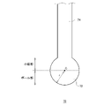
- Fig. 2 shows the tip shape of the dummy tool.
- the dummy tool 70 has a spherical portion 72 having a center c and a cylindrical portion 74 connected to the spherical portion 72 .
- the spherical portion 72 is a spherical component having a spherical shape, and has a hemispherical ball portion forming the lower end side and a small diameter portion connected to the ball portion.
- the center c of the spherical portion 72 is positioned on the central axis of the dummy tool 70 .
- the reduced diameter portion has a circular cross-section in a direction perpendicular to the tool axis, the radius of the circular cross-section being smaller than the radius r of the ball portion.
- the small-diameter portion of the spherical portion 72 shown in FIG. 2 has a shape obtained by removing the top side of a hemisphere with a radius of r along a plane perpendicular to the axis, and a cylindrical portion 74 is connected to the notched top side surface.
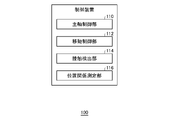
- FIG. 3 shows functional blocks of the control device 100.
- the control device 100 includes a spindle control section 110 , a movement control section 112 , a contact detection section 114 and a positional relationship measurement section 116 .
- a spindle controller 110 controls rotation of the spindle 46 by the rotation mechanism, and a movement controller 112 controls relative movement between the dummy tool 70 and the reference block 60 by the feed mechanism.
- each element described as a functional block that performs various processes can be configured by a circuit block, memory, or other LSI in terms of hardware, and is loaded in memory in terms of software. It is realized by a program or the like. Therefore, those skilled in the art will understand that these functional blocks can be realized in various forms by hardware only, software only, or a combination thereof, and are not limited to either one.
- the contact detection unit 114 detects contact between the dummy tool 70 and the reference block 60.
- the contact detection section 114 may have a contact sensor that detects contact of the dummy tool 70 with the reference block 60 .
- the contact sensor may be, for example, a force sensor that detects force applied upon contact, or a sensor that detects conduction when the dummy tool 70 and the reference block 60 come into contact with each other.
- the processing apparatus 1 of the embodiment has a function of analyzing internal information of the processing apparatus 1 that changes when the dummy tool 70 contacts the reference block 60 and detecting contact between the dummy tool 70 and the reference block 60.
- detection values related to the control of the motor included in the feed mechanism for example, current measurement value, current command value, position deviation, torque command value, torque estimation value, etc.
- a sensor for detecting contact is not required, but a sensor may be provided for the purpose of improving detection accuracy.
- the control device 100 of the embodiment drives and controls the motor of the feed mechanism to achieve relative movement between the dummy tool 70 and the reference block 60 .
- the control device 100 may detect the contact between the dummy tool 70 and the reference block 60 based on the motor torque waveform when the dummy tool 70 and the reference block 60 approach each other and come into contact with each other.
- the feed mechanism consists of mechanical elements such as a ball screw mechanism, it inevitably has mechanical resistance.
- the torque waveform of the motor of the feed mechanism is affected by mechanical resistance and includes small-amplitude fluctuation components.
- These fluctuation components include periodic components dependent on the angular position (rotational angular position) of the screw shaft and bearings, the translational position of the linear guide, the revolution position of the ball screw, the bearing, and the rolling elements in the linear guide, and the rotation position. Contains a periodic component. Fluctuations due to the mechanical resistance of these elements are basically due to geometrical errors of each guide surface and each rolling element and thus depend on the position of the feed mechanism. Therefore, when detecting the contact between the dummy tool 70 and the reference block 60 using the change in the torque detection value, the torque fluctuation component based on the mechanical resistance is removed from the acquired motor torque waveform at each feed position. is preferred.
- FIG. 4 shows an example of a flowchart for detecting contact between the dummy tool 70 and the reference block 60.
- the movement control unit 112 moves either the reference block 60 or the dummy tool 70 along the first path so that the reference block 60 and the dummy tool 70 do not contact each other, and the contact detection unit 114 detects the A first torque detection value of a motor included in the feed mechanism is acquired at a plurality of feed positions (S10).
- FIG. 5 is a diagram for explaining the step of S10.
- the reference block 60 has a known rectangular parallelepiped shape, and has at least a reference surface that is erected and an upper surface that constitutes the top.
- FIG. You may move in any direction. 1
- the X-axis motor 20 moves the second table 18 in the X-axis direction
- the X-axis sensor 30 detects the position of the second table 18 in the X-axis direction.
- the X-axis motor 20 moves the main shaft 46 in the X-axis direction
- the X-axis sensor 30 detects the position of the main shaft 46 in the X-axis direction.
- the movement control unit 112 sets the initial position (x 0 , y 0 , z 0 ) of the center c of the spherical portion 72 on the first path as follows. do.
- x 0 coordinate value away in the negative direction of the X-axis from the coordinate value x 1
- the reference plane is arranged y 0 : coordinate value overlapping the width position of the reference plane on the y-axis z 0 : spherical portion 72 from the upper surface of the reference block
- z 0 coordinate value away in the negative direction of the X-axis from the coordinate value x 1
- y 0 coordinate value overlapping the width position of the reference plane on the y-axis
- z 0 spherical portion 72 from the upper surface of the reference block
- the movement control unit 112 sets the end position (x 2 , y 0 , z 0 ) of the first path to a position where part or all of the sphere 72 overlaps the upper surface of the reference block 60 when viewed from the z-axis direction. do.
- x 2 > x 1 ⁇ (radius r of spherical portion 72) If it is
- the movement control unit 112 arranges the center c of the spherical portion 72 at the initial position (x 0 , y 0 , z 0 ) based on the detection values of the X-axis sensor 30, the Y-axis sensor 32, and the Z-axis sensor 34,
- the dummy tool 70 is moved to the end position (x 2 , y 0 , z 0 ) of the first path at a predetermined speed. Since the height of the sphere center c is maintained at z0 during movement in the first path, the sphere 72 passes over the upper surface without contacting the reference surface.
- the contact detection unit 114 acquires the first torque detection value of the X-axis motor 20 included in the feed mechanism at a plurality of feed positions on the first route.
- a first torque waveform 80 indicates a first torque detection value of the X-axis motor 20 obtained in association with the x-coordinate value at a predetermined sampling period while the dummy tool 70 is moving along the first path.
- the x-coordinate value is derived from the detected value of the X-axis sensor 30 .
- the ball screw included in the feed mechanism, the bearings that support it, the linear guide mechanism, the coupling, etc. have mechanical resistance. Includes amplitude fluctuation components.
- the contact detection unit 114 associates the coordinate value of the sphere center c with the first torque detection value and records them in a recording unit (not shown).
- movement control unit 112 moves either reference block 60 or dummy tool 70 to a second path parallel to the first path so that reference block 60 and dummy tool 70 are in contact with each other.
- the contact detection unit 114 acquires the second torque detection value of the motor included in the feed mechanism at a plurality of feed positions on the second route (S12).
- FIG. 6 is a diagram for explaining the step of S12.
- the movement control unit 112 moves the center c of the spherical portion 72 of the dummy tool 70 to the initial position (x 0 , y 0 , z 1 ) of the second path in order to start the step of S12. Moving.
- the initial position of the second path has a displaced z-coordinate value.
- z1 is set as follows.
- z 1 coordinate value below the position lower than the radius r of the spherical portion 72 from the upper surface of the reference block, that is, z 1 is z 1 ⁇ (height of top surface of reference block) ⁇ (radius r of spherical portion 72) is expressed as
- the movement control unit 112 sets the end position of the second route to a position (x 2 , y 0 , z 1 ) displaced in the Z-axis direction from the end position (x 2 , y 0 , z 0 ) of the first route.
- the movement control unit 112 may set the end position of the second route to the coordinate values (x 3 , y 0 , z 1 ).
- the movement control unit 112 arranges the center c of the spherical portion 72 at the initial position (x 0 , y 0 , z 1 ) based on the detection values of the X-axis sensor 30, the Y-axis sensor 32, and the Z-axis sensor 34,
- the dummy tool 70 is moved to the end position of the second path at the same speed as the moving speed in step S10.
- the height of the sphere center c is maintained at z1, so the sphere 72 contacts the reference plane.
- the movement control unit 112 may forcibly end the movement of the dummy tool 70 before the end position of the second path.
- the motor torque value is set to a threshold value for terminating movement, and the movement control unit 112 forcibly stops the feed mechanism at the moment when the motor torque value exceeds the threshold value, even if the relative movement on the second path ends. good.
- the contact detection unit 114 acquires the second torque detection value of the X-axis motor 20 included in the feed mechanism at a plurality of feed positions on the second route.
- the second torque waveform 82 indicates the second torque detection value of the X-axis motor 20 obtained in association with the x-coordinate value at a predetermined sampling period while the dummy tool 70 is moving along the second path.
- the x-coordinate value is derived from the detected value of the X-axis sensor 30 .
- the contact detection unit 114 associates the coordinate value of the sphere center c with the second torque detection value and records them in a recording unit (not shown).
- the dummy tool 70 cannot move any more after contacting the reference block 60.
- the X-axis sensor 30 moves the ball center c. Outputs a detection value indicating that At this time, the load on the contact point increases, and the motor torque rises sharply. Therefore, by specifying the x-coordinate value at which the motor torque begins to rise sharply, the x-coordinate value of the sphere center c at the time of contact can be derived. It is difficult to specify accurate contact timing and accurate contact position from the second torque waveform 82 because it contains fluctuation components based on mechanical resistance.
- the contact detection unit 114 uses the first torque waveform 80 obtained in step S10 to remove the fluctuation component due to mechanical resistance from the second torque waveform 82 obtained in step S12.
- the contact detection unit 114 derives a difference value between the first detection value and the second detection value acquired at each feeding position corresponding to each other on the first route and the second route (S14).
- the mutually corresponding feed positions are positions at which the operating states of the feed mechanisms are synchronized, specifically, positions having the same x-coordinate value. Therefore, the contact detection unit 114 reads out the second torque detection value and the first torque detection value associated with the same x-coordinate value in the recording unit (not shown), and derives a difference value.
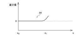
- FIG. 7 shows a differential waveform 84 obtained by subtracting the first torque waveform 80 from the second torque waveform 82.
- FIG. A differential waveform 84 is constructed by connecting differential values derived for a plurality of x-coordinate values. Since the operating state of the feed mechanism is the same in the first path and the second path before contact, the torque waveforms containing fluctuation components due to mechanical resistance match, and the differential waveform 84 exhibits a value of substantially zero. On the other hand, at the x position after the contact between the reference block 60 and the dummy tool 70 on the second path, the difference value changes from 0 due to the contact load. Therefore, the contact detection section 114 can detect contact between the dummy tool 70 and the reference block 60 based on the change in the difference value in the difference waveform 84 (S16).
- the contact detection unit 114 may detect contact between the dummy tool 70 and the reference block 60 when the difference value exceeds a predetermined threshold.
- the difference waveform 84 since the amplitude component caused by the mechanical resistance is removed, the increase in motor torque due to contact is reproduced with high accuracy. It is possible to accurately derive the x-coordinate value of the sphere center c at the time of contact.
- the contact detection unit 114 can also detect contact between the dummy tool 70 and the reference block 60 using the technique disclosed in Patent Document 1. Specifically, the contact detection unit 114 detects contact based on a regression formula obtained by performing regression analysis of an average value of a plurality of difference values before contact and a plurality of difference values after contact, and detects a contact position. may be specified.
- step S10 was performed before step S12, but the order of implementation may be changed. Alternatively, step S10 may be performed multiple times and the averaged first torque waveform 80 may be used. Further, in the embodiment, the torque detection value estimated by the torque estimation function installed in the processing apparatus 1 is used as the detection value related to the control of the motor included in the feed mechanism, but in the processing apparatus 1 without the torque estimation function may perform contact detection using a detected value related to motor control, such as a measured current value of the motor.
- the dummy tool 70 and the reference block 60 are moved relative to each other in the direction perpendicular to the rotation axis of the spindle 46, and contact is detected to identify the relative positional relationship between the rotation axis and the reference block 60. did.
- the dummy tool 70 and the reference block 60 are relatively moved in a direction parallel to the rotation axis of the main shaft 46 so that the upper surface of the reference block 60 and the dummy tool 70 (assuming that the projection length is known) come into contact with each other.
- the detection may identify the relative positional relationship between the shaft end of the main shaft 46 and the reference block 60 .
- the contact detection unit 114 can detect contact between the dummy tool 70 and the reference block 60 to identify the contact position.
- the contact detection unit 114 may have a contact sensor, detect contact from data sensed by the contact sensor, and acquire coordinate values at the time of contact.
- a method for measuring the relative positional relationship between the axis of the main shaft 46 and the reference block 60 by the positional relationship measuring unit 116 will be described below on the premise that the contact detecting unit 114 has a highly accurate contact detecting function. do. In this method, when the dummy tool 70 is eccentrically attached to the spindle 46, the relative positional relationship is identified by removing the influence of the eccentricity.
- FIG. 8 shows a state in which the dummy tool 70 is attached to the holder 48.
- FIG. In an ideal mounting state, the axis of the main shaft 46 and the center axis of the dummy tool 70 are aligned. The center axes of the dummy tools 70 often do not match.
- the center c of the ball portion 72 In the attached state shown in FIG. 8, the center c of the ball portion 72 is eccentric from the axis of the main shaft 46 .
- a method for accurately measuring the relative positional relationship between the axis of the main shaft 46 and the reference block 60 will be described below even when the spherical center c is eccentric from the axis of the main shaft 46 .
- FIG. 9 shows an example of a flow chart for measuring the relative positional relationship between the axis of the main shaft 46 and the reference block 60 .
- two contact steps are performed with different angular positions of the spindle 46 .
- the angular position of the main shaft 46 may be detected by the main shaft sensor 42 as the angular position of rotation from a predetermined origin.
- the movement control unit 112 moves the dummy tool 70 relative to the reference block 60 to bring the reference block 60 and the dummy tool 70 into contact (S20).
- the contact detection unit 114 acquires the first coordinate value of the reference point when the reference block 60 and the dummy tool 70 contact each other (S22).
- the reference point is the center c of the spherical portion 72 in the embodiment, another position on the dummy tool 70 may be used as the reference point.
- ⁇ Second contact step> Subsequently, the spindle control unit 110 rotates the spindle 46 about its axis by 180 degrees from the angular position of the spindle 46 in the first contact step (S24). Then, the movement control unit 112 moves the dummy tool 70 relative to the reference block 60 to bring the reference block 60 and the dummy tool 70 into contact (S26). The contact detection unit 114 acquires the second coordinate value of the reference point when the reference block 60 and the dummy tool 70 contact each other (S28).
- the positional relationship measuring section 116 derives the relative positional relationship between the axis of the main shaft 46 and the reference block 60 from the first coordinate value and the second coordinate value. (S30).
- the measurement method of the embodiment will be described below based on specific examples.
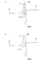
- FIG. 10(a) shows the state of the first contacting step.
- the movement control unit 112 moves the dummy tool 70 relative to the reference plane of the reference block 60 in the X-axis direction so that the spherical portion 72 of the dummy tool 70 moves toward the reference plane of the reference block 60 . come into contact with
- the contact detection unit 114 acquires the first coordinate values (x 4 , y 4 , z 4 ) of the sphere center c.
- the position x4 obtained as the x-coordinate value of the sphere center c is the x - position of the main shaft 46 detected by the X-axis sensor 30, and the contact detection unit 114 detects the x-position of the main shaft 46 and the sphere center. Assuming that the x-position of c is equal (there is no eccentricity), the x-position of the sphere center c is obtained. Therefore, if the sphere center c is eccentric in the X-axis direction from the spindle axis, the acquired position x4 of the sphere center c is shifted from the actual x position by the amount of eccentricity.
- FIG. 10(b) shows the state of the second contacting step.
- the movement controller 112 moves the reference plane of the reference block 60.
- the dummy tool 70 is relatively moved in the X-axis direction to bring the spherical portion 72 of the dummy tool 70 into contact with the reference surface of the reference block 60 .
- the movement path of the sphere center c in the second contact step is the same as the movement path of the sphere center c in the first contact step.
- the contact detection unit 114 acquires the second coordinate values (x 5 , y 4 , z 4 ) of the sphere center c.
- the position x 5 obtained as the x-coordinate value of the sphere center c as described above is actually the x-position of the main shaft 46 detected by the X-axis sensor 30 .
- the positional relationship measurement unit 116 derives the relative positional relationship between the coordinate values between the first coordinate value and the second coordinate value and the reference plane. Specifically, the positional relationship measuring unit 116 derives the relative positional relationship between the coordinate value of the midpoint between the first coordinate value and the second coordinate value and the reference plane.
- the coordinates of the midpoint are obtained as follows. Coordinate value of midpoint ((x 4 +x 5 )/2, y 4 , z 4 )
- the positional relationship measurement unit 116 may identify the x-coordinate value (x 4 +x 5 )/2 as the x-position of the axis of the main shaft 46 with respect to the reference plane.
- the influence of the eccentricity of the spherical portion 72 is removed, and the relative positional relationship between the axis of the main shaft 46 and the reference block 60 is accurately identified. can.
- the coordinate value of the midpoint was obtained, but the positional relationship measurement unit 116 should derive the central position of the two coordinate values at least in the movement direction (X-axis direction).
- the movement control unit 112 performs two contact steps, and the positional relationship measurement unit 116 determines the relative position between the axis center and the reference block 60 from the coordinate values of the sphere center c at the time of the two contact steps. We derived a typical positional relationship.
- the movement control unit 112 performs the contact process three or more times, and the positional relationship measurement unit 116 determines the relative positional relationship between the axis center and the reference block 60 from three or more coordinate values. can be derived. By increasing the number of contacts, the relative positional relationship can be derived with high accuracy.
- the movement control unit 112 moves the dummy tool 70 in the X-axis direction relative to the reference surface of the reference block 60 at a plurality of different angular positions of the main shaft 46, thereby moving the spherical portion of the dummy tool 70. 72 is brought into contact with the reference surface of reference block 60 . After bringing the spherical portion 72 into contact with the reference block 60, the movement control portion 112 separates the spherical portion 72 from the reference block 60, and the main shaft control portion 110 shifts the main shaft 46 from the angular position of the main shaft 46 at that time. After rotating N degrees around, movement control unit 112 again brings ball 72 into contact with reference block 60 .
- the spindle controller 110 rotates the spindle 46 about the axis N degrees from the angular position of the spindle 46 in the previous contact process, so that the movement controller 112 moves the spindle Sphere 72 contacts reference block 60 at a plurality of 46 different angular positions.
- the movement control unit 112 may bring the reference block 60 and the ball portion 72 into contact at least (360/N) times while changing the angular position of the main shaft 46 .
- the rotation angle N is set such that (360/N) is an integer.
- the contact detection unit 114 acquires the coordinate values of the spherical portion center c when the spherical portion 72 and the reference surface of the reference block 60 contact each other at different angular positions of the main shaft 46 .
- a positional relationship measurement unit 116 derives a relative positional relationship between the rotation axis and the reference block 60 from the plurality of coordinate values acquired by the contact detection unit 114 . Note that the positional relationship measurement unit 116 may derive the average value of the plurality of coordinate values and the relative positional relationship with the reference plane.
- the reference block 60 has a first reference surface and a second reference surface facing the first reference surface.
- the reference block 60 has a rectangular parallelepiped shape, and the first reference plane and the second reference plane are parallel to each other.
- FIG. 11(a) shows the state of the first contacting step.
- the movement control unit 112 relatively moves the dummy tool 70 in the X-axis positive direction with respect to the first reference plane of the reference block 60 so that the spherical portion 72 of the dummy tool 70 moves toward the reference block 60 .
- the contact detection unit 114 acquires the first coordinate values (x 6 , y 6 , z 6 ) of the sphere center c.
- the position x 6 obtained here as the x-coordinate value of the sphere center c is actually the x-position of the main shaft 46 detected by the X-axis sensor 30 .
- FIG. 11(b) shows the state of the second contacting step.
- the movement controller 112 moves the dummy tool 70 relative to the second reference surface of the reference block 60 by X.
- the ball portion 72 of the dummy tool 70 is brought into contact with the second reference surface of the reference block 60 .
- the movement direction of the sphere center c in the second contact step is opposite to the movement direction of the sphere center c in the first contact step.
- the contact detection unit 114 acquires the second coordinate values (x 7 , y 6 , z 6 ) of the sphere center c.
- the positional relationship measuring unit 116 derives the relative positional relationship between the axis of the main shaft 46 and the position between the first reference plane and the second reference plane. Specifically, the positional relationship measuring unit 116 derives the relative positional relationship between the axis of the main shaft 46 and the central positions of the first reference plane and the second reference plane.
- the x-coordinate value of the center position is obtained as follows. x-coordinate value of center position (x 6 +x 7 )/2
- the control device 100 may identify the x-coordinate value (x 6 +x 7 )/2 as the center position of the reference block 60 in the X-axis direction. By rotating the main shaft 46 by 180 degrees in the second contacting step, the influence of the eccentricity of the spherical portion 72 is removed, and the relative positional relationship between the axis of the main shaft 46 and the reference block 60 is accurately identified. can.
- the present disclosure has been described above based on the embodiments. It should be understood by those skilled in the art that this embodiment is an example, and that various modifications can be made to combinations of each component and each treatment process, and such modifications are also within the scope of the present disclosure. .
- the dummy tool 70 is brought into contact with the reference block 60 having a known shape in the embodiment, it may be brought into contact with the work material 62 .
- a dummy tool 70 without cutting ability is used as a tool to be brought into contact with the reference block 60, but a rotary tool may be used.
- the rotary tool may be, for example, a ball end mill having a hemispherical ball portion, and when using a ball end mill, the method of measuring the relative positional relationship described with reference to FIG. 11 can be realized.
- the object that the rotary tool comes into contact with is not the reference block 60 but may be cut (creating scratches). It is preferably an object, such as a work piece 62 .
- the rotary tool has a root portion with a cylindrical surface or a conical surface on which no cutting edge is formed, and this root portion may be brought into contact with the reference block 60 or the workpiece 62 .
- FIG. 12 shows how the base of the rotary tool is brought into contact with the reference surface of the reference block 60.
- the spindle 46 does not need to rotate because the root portion has a cylindrical or conical surface unlike the cutting edge.
- the contact surface on the tool side is a cylindrical surface or a conical surface in this way, the contact surface on the reference block 60 or the workpiece 62 side is designed to prevent the contact point from becoming a sharp corner. It is desirable to have a gentle convex curvature in the direction of rotation.
- a positional relationship measuring method is a method of measuring the relative positional relationship between the axis of a main shaft and an object, in which a tool attached to the main shaft is moved relative to the object.
- the moving step brings the object and the tool into contact at different angular positions of the main axis
- the coordinate value acquisition step acquires the coordinate values of the reference point when the object and the tool come into contact at different angular positions of the main axis
- the measuring step the relative positional relationship between the axis and the object is derived from the acquired plurality of coordinate values.
- the moving step includes a first moving step of relatively moving the tool attached to the main shaft with respect to the object so that the object and the tool come into contact with each other; and at least a second moving step of moving the tool relative to the object after rotating N degrees around the center to bring the object and tool into contact.
- the moving step may contact the object and the tool at least (360/N) times.
- the rotation angle N is set so that (360/N) is an integer.
- the object has one reference plane
- the moving step brings the tool into contact with the reference plane of the object
- the measuring step derives an average value of a plurality of coordinate values and a relative positional relationship with the reference plane.
- the object has a first reference surface and a second reference surface opposite to the first reference surface
- the first moving step includes bringing the tool into contact with the first reference surface of the object
- the second moving step may contact the tool with a second reference surface of the object
- the measuring step may derive a relative positional relationship between the axis and the position between the first and second reference surfaces.
- the relative positional relationship between the axis and the position between the first reference plane and the second reference plane is obtained by bringing the tool into contact with the two opposing reference planes and acquiring the coordinate values of the respective reference points. can be derived.
- the measuring step may derive a relative positional relationship between the axis and the central positions of the first reference plane and the second reference plane.
- the tool may have a spherical part, and the spherical part may come into contact with the object.
- the tool may be a rotating tool such as an end mill, and the object may come into contact with the root portion having a cylindrical or conical surface or the rotating cutting edge portion.
- the root need not be rotating when the root and the object come into contact.
- a processing apparatus includes a rotation mechanism that rotates a spindle to which a tool is attached, a feed mechanism that moves the tool relative to an object, rotation of the spindle by the rotation mechanism and the tool by the feed mechanism. and a control device for controlling the relative movement of the The control device brings the object and the tool into contact with each other at different angular positions of the spindle, acquires the coordinate values of the reference point when the object and the tool come into contact, and calculates the distance between the axis center and the object from the multiple acquired coordinate values. Derive the relative positional relationship.
- a contact detection method is a method of detecting contact between a tool attached to a spindle and an object, wherein one of the object and the tool is first moved to prevent contact between the object and the tool.
- contact between the tool and the object can be detected with high accuracy.
- a processing apparatus includes a feed mechanism that moves a tool relative to an object, and a controller that controls the relative movement of the tool by the feed mechanism, wherein the controller controls the object and moving one of the object or the tool along the first path without contact with the tool, and obtaining a first detection value for control of a motor included in the feed mechanism at a plurality of positions on the first path; One of the object or the tool is moved along a second path parallel to the first path to bring the object and tool into contact, and at a plurality of positions on the second path a second movement of the motor associated with the feed mechanism is controlled.
- the present disclosure can be used in the field of processing technology.
Landscapes
- Engineering & Computer Science (AREA)
- Mechanical Engineering (AREA)
- Automatic Control Of Machine Tools (AREA)
- Milling Processes (AREA)
- Machine Tool Sensing Apparatuses (AREA)
- Numerical Control (AREA)
Priority Applications (4)
| Application Number | Priority Date | Filing Date | Title |
|---|---|---|---|
| PCT/JP2021/003461 WO2022162927A1 (ja) | 2021-02-01 | 2021-02-01 | 位置関係測定方法、接触検出方法および加工装置 |
| JP2021555512A JP7285595B2 (ja) | 2021-02-01 | 2021-02-01 | 接触検出方法および加工装置 |
| CN202180003303.7A CN113840688A (zh) | 2021-02-01 | 2021-02-01 | 位置关系测定方法、接触检测方法和加工装置 |
| US17/671,339 US20220241924A1 (en) | 2021-02-01 | 2022-02-14 | Contact detection method |
Applications Claiming Priority (1)
| Application Number | Priority Date | Filing Date | Title |
|---|---|---|---|
| PCT/JP2021/003461 WO2022162927A1 (ja) | 2021-02-01 | 2021-02-01 | 位置関係測定方法、接触検出方法および加工装置 |
Related Child Applications (1)
| Application Number | Title | Priority Date | Filing Date |
|---|---|---|---|
| US17/671,339 Continuation US20220241924A1 (en) | 2021-02-01 | 2022-02-14 | Contact detection method |
Publications (1)
| Publication Number | Publication Date |
|---|---|
| WO2022162927A1 true WO2022162927A1 (ja) | 2022-08-04 |
Family
ID=78971958
Family Applications (1)
| Application Number | Title | Priority Date | Filing Date |
|---|---|---|---|
| PCT/JP2021/003461 Ceased WO2022162927A1 (ja) | 2021-02-01 | 2021-02-01 | 位置関係測定方法、接触検出方法および加工装置 |
Country Status (4)
| Country | Link |
|---|---|
| US (1) | US20220241924A1 (https=) |
| JP (1) | JP7285595B2 (https=) |
| CN (1) | CN113840688A (https=) |
| WO (1) | WO2022162927A1 (https=) |
Cited By (1)
| Publication number | Priority date | Publication date | Assignee | Title |
|---|---|---|---|---|
| WO2024053127A1 (ja) * | 2022-09-08 | 2024-03-14 | 国立大学法人東海国立大学機構 | 接触位置検出方法および加工装置 |
Families Citing this family (1)
| Publication number | Priority date | Publication date | Assignee | Title |
|---|---|---|---|---|
| CN119159380B (zh) * | 2024-11-22 | 2025-03-11 | 江苏亿鼎传动机械有限公司 | 一种齿轮加工机床带曲面检测的齿轮加工设备及方法 |
Citations (5)
| Publication number | Priority date | Publication date | Assignee | Title |
|---|---|---|---|---|
| JPH1195821A (ja) * | 1997-09-18 | 1999-04-09 | Mitsubishi Electric Corp | 接触検出方法および装置 |
| JP2002120129A (ja) * | 2000-10-11 | 2002-04-23 | Fuji Seiko Ltd | 導電膜付切削工具およびその使用方法 |
| JP2008105134A (ja) * | 2006-10-25 | 2008-05-08 | Citizen Holdings Co Ltd | 工作機械及び加工方法 |
| JP2019195869A (ja) * | 2018-05-08 | 2019-11-14 | Dgshape株式会社 | 補正装置および補正方法 |
| JP2020196051A (ja) * | 2019-05-30 | 2020-12-10 | オークマ株式会社 | 工作機械対象物の位置計測方法及び位置計測システム |
Family Cites Families (9)
| Publication number | Priority date | Publication date | Assignee | Title |
|---|---|---|---|---|
| SG149688A1 (en) * | 2002-02-25 | 2009-02-27 | Daikin Ind Ltd | Motor control method and its apparatus |
| JP2006192516A (ja) * | 2005-01-11 | 2006-07-27 | Canon Electronics Inc | 工作機械およびワーク測定装置ならびにワーク測定方法 |
| WO2010032284A1 (ja) * | 2008-09-16 | 2010-03-25 | 新日本工機株式会社 | 数値制御装置 |
| JP5218470B2 (ja) * | 2010-04-28 | 2013-06-26 | 株式会社安川電機 | ロボットの作業成否判定装置、および方法 |
| JP4808283B1 (ja) * | 2010-06-30 | 2011-11-02 | 株式会社新川 | 電子部品実装装置及び電子部品実装方法 |
| EP2745999A1 (en) * | 2011-08-19 | 2014-06-25 | Kabushiki Kaisha Yaskawa Denki | Robot system, robot control device, robot hand and method for controlling robot |
| WO2018047312A1 (ja) * | 2016-09-09 | 2018-03-15 | 株式会社牧野フライス製作所 | ワーク測定方法 |
| JP6662835B2 (ja) * | 2017-10-18 | 2020-03-11 | ファナック株式会社 | 制御装置 |
| JP6559274B2 (ja) | 2018-01-29 | 2019-08-14 | 株式会社牧野フライス製作所 | 工具測定装置およびワーク測定装置の校正方法、校正装置ならびに標準器 |
-
2021
- 2021-02-01 CN CN202180003303.7A patent/CN113840688A/zh active Pending
- 2021-02-01 WO PCT/JP2021/003461 patent/WO2022162927A1/ja not_active Ceased
- 2021-02-01 JP JP2021555512A patent/JP7285595B2/ja active Active
-
2022
- 2022-02-14 US US17/671,339 patent/US20220241924A1/en not_active Abandoned
Patent Citations (5)
| Publication number | Priority date | Publication date | Assignee | Title |
|---|---|---|---|---|
| JPH1195821A (ja) * | 1997-09-18 | 1999-04-09 | Mitsubishi Electric Corp | 接触検出方法および装置 |
| JP2002120129A (ja) * | 2000-10-11 | 2002-04-23 | Fuji Seiko Ltd | 導電膜付切削工具およびその使用方法 |
| JP2008105134A (ja) * | 2006-10-25 | 2008-05-08 | Citizen Holdings Co Ltd | 工作機械及び加工方法 |
| JP2019195869A (ja) * | 2018-05-08 | 2019-11-14 | Dgshape株式会社 | 補正装置および補正方法 |
| JP2020196051A (ja) * | 2019-05-30 | 2020-12-10 | オークマ株式会社 | 工作機械対象物の位置計測方法及び位置計測システム |
Cited By (1)
| Publication number | Priority date | Publication date | Assignee | Title |
|---|---|---|---|---|
| WO2024053127A1 (ja) * | 2022-09-08 | 2024-03-14 | 国立大学法人東海国立大学機構 | 接触位置検出方法および加工装置 |
Also Published As
| Publication number | Publication date |
|---|---|
| CN113840688A (zh) | 2021-12-24 |
| JPWO2022162927A1 (https=) | 2022-08-04 |
| JP7285595B2 (ja) | 2023-06-02 |
| US20220241924A1 (en) | 2022-08-04 |
Similar Documents
| Publication | Publication Date | Title |
|---|---|---|
| JP4276270B2 (ja) | 接触検知によるワークの基準位置設定機能を有する工作機械 | |
| JP5836314B2 (ja) | 工作機械の較正方法 | |
| JP6955296B2 (ja) | 切削装置および接触位置特定プログラム | |
| JP2911753B2 (ja) | 多座標接触系で異なった接触力の比率を検出して補償する校正方法 | |
| JP4612086B2 (ja) | ワークの計測基準点設定機能を有する工作機械 | |
| JP2016083729A (ja) | 幾何誤差同定システム、及び幾何誤差同定方法 | |
| JP2009519137A5 (https=) | ||
| US20230152772A1 (en) | Positional relationship measurement method and machining apparatus | |
| JP7285595B2 (ja) | 接触検出方法および加工装置 | |
| JP2023010002A (ja) | 工作機械の誤差同定方法、誤差同定プログラム、工作機械 | |
| JP5740201B2 (ja) | 幾何誤差同定装置 | |
| KR102840795B1 (ko) | 공작기계 주축의 동심도 보정 장치 및 보정 방법 | |
| JP2014503369A (ja) | 光学エレメントを中心配置する方法 | |
| JP6615285B1 (ja) | 工具振れ調整方法および工作機械 | |
| JP3880030B2 (ja) | V溝形状測定方法及び装置 | |
| JP6506149B2 (ja) | 工作機械の幾何誤差同定方法及び幾何誤差同定プログラム | |
| JP2023017410A (ja) | 測定装置および穴位置検出方法 | |
| JP7074381B2 (ja) | 切削装置 | |
| JP2015039732A (ja) | 工作機械及び工作機械を用いたワーク加工部測定方法 | |
| JP3939805B2 (ja) | Nc工作機械用ワーク測定方法 | |
| EP3418682B1 (en) | Measuring method using touch probe | |
| JPH07121498B2 (ja) | 機械の運動精度測定装置 | |
| JPS60177848A (ja) | 数値制御工作機における原点補正方法 | |
| JP2011036959A (ja) | 工作機械のタッチプローブのキャリブレーション方法及び工作機械 | |
| JP2024146992A (ja) | プログラム及び工作機械 |
Legal Events
| Date | Code | Title | Description |
|---|---|---|---|
| ENP | Entry into the national phase |
Ref document number: 2021555512 Country of ref document: JP Kind code of ref document: A |
|
| 121 | Ep: the epo has been informed by wipo that ep was designated in this application |
Ref document number: 21922940 Country of ref document: EP Kind code of ref document: A1 |
|
| NENP | Non-entry into the national phase |
Ref country code: DE |
|
| 122 | Ep: pct application non-entry in european phase |
Ref document number: 21922940 Country of ref document: EP Kind code of ref document: A1 |