WO2022158482A1 - 光学積層体および画像表示装置 - Google Patents
光学積層体および画像表示装置 Download PDFInfo
- Publication number
- WO2022158482A1 WO2022158482A1 PCT/JP2022/001758 JP2022001758W WO2022158482A1 WO 2022158482 A1 WO2022158482 A1 WO 2022158482A1 JP 2022001758 W JP2022001758 W JP 2022001758W WO 2022158482 A1 WO2022158482 A1 WO 2022158482A1
- Authority
- WO
- WIPO (PCT)
- Prior art keywords
- layer
- retardation
- film
- liquid crystal
- optical laminate
- Prior art date
- Legal status (The legal status is an assumption and is not a legal conclusion. Google has not performed a legal analysis and makes no representation as to the accuracy of the status listed.)
- Ceased
Links
Images


Classifications
-
- G—PHYSICS
- G02—OPTICS
- G02B—OPTICAL ELEMENTS, SYSTEMS OR APPARATUS
- G02B5/00—Optical elements other than lenses
- G02B5/30—Polarising elements
- G02B5/3016—Polarising elements involving passive liquid crystal elements
-
- B—PERFORMING OPERATIONS; TRANSPORTING
- B32—LAYERED PRODUCTS
- B32B—LAYERED PRODUCTS, i.e. PRODUCTS BUILT-UP OF STRATA OF FLAT OR NON-FLAT, e.g. CELLULAR OR HONEYCOMB, FORM
- B32B27/00—Layered products comprising a layer of synthetic resin
-
- B—PERFORMING OPERATIONS; TRANSPORTING
- B32—LAYERED PRODUCTS
- B32B—LAYERED PRODUCTS, i.e. PRODUCTS BUILT-UP OF STRATA OF FLAT OR NON-FLAT, e.g. CELLULAR OR HONEYCOMB, FORM
- B32B7/00—Layered products characterised by the relation between layers; Layered products characterised by the relative orientation of features between layers, or by the relative values of a measurable parameter between layers, i.e. products comprising layers having different physical, chemical or physicochemical properties; Layered products characterised by the interconnection of layers
- B32B7/02—Physical, chemical or physicochemical properties
- B32B7/023—Optical properties
-
- C—CHEMISTRY; METALLURGY
- C09—DYES; PAINTS; POLISHES; NATURAL RESINS; ADHESIVES; COMPOSITIONS NOT OTHERWISE PROVIDED FOR; APPLICATIONS OF MATERIALS NOT OTHERWISE PROVIDED FOR
- C09J—ADHESIVES; NON-MECHANICAL ASPECTS OF ADHESIVE PROCESSES IN GENERAL; ADHESIVE PROCESSES NOT PROVIDED FOR ELSEWHERE; USE OF MATERIALS AS ADHESIVES
- C09J201/00—Adhesives based on unspecified macromolecular compounds
-
- C—CHEMISTRY; METALLURGY
- C09—DYES; PAINTS; POLISHES; NATURAL RESINS; ADHESIVES; COMPOSITIONS NOT OTHERWISE PROVIDED FOR; APPLICATIONS OF MATERIALS NOT OTHERWISE PROVIDED FOR
- C09J—ADHESIVES; NON-MECHANICAL ASPECTS OF ADHESIVE PROCESSES IN GENERAL; ADHESIVE PROCESSES NOT PROVIDED FOR ELSEWHERE; USE OF MATERIALS AS ADHESIVES
- C09J7/00—Adhesives in the form of films or foils
- C09J7/20—Adhesives in the form of films or foils characterised by their carriers
- C09J7/22—Plastics; Metallised plastics
- C09J7/24—Plastics; Metallised plastics based on macromolecular compounds obtained by reactions involving only carbon-to-carbon unsaturated bonds
-
- C—CHEMISTRY; METALLURGY
- C09—DYES; PAINTS; POLISHES; NATURAL RESINS; ADHESIVES; COMPOSITIONS NOT OTHERWISE PROVIDED FOR; APPLICATIONS OF MATERIALS NOT OTHERWISE PROVIDED FOR
- C09J—ADHESIVES; NON-MECHANICAL ASPECTS OF ADHESIVE PROCESSES IN GENERAL; ADHESIVE PROCESSES NOT PROVIDED FOR ELSEWHERE; USE OF MATERIALS AS ADHESIVES
- C09J7/00—Adhesives in the form of films or foils
- C09J7/20—Adhesives in the form of films or foils characterised by their carriers
- C09J7/29—Laminated material
-
- C—CHEMISTRY; METALLURGY
- C09—DYES; PAINTS; POLISHES; NATURAL RESINS; ADHESIVES; COMPOSITIONS NOT OTHERWISE PROVIDED FOR; APPLICATIONS OF MATERIALS NOT OTHERWISE PROVIDED FOR
- C09J—ADHESIVES; NON-MECHANICAL ASPECTS OF ADHESIVE PROCESSES IN GENERAL; ADHESIVE PROCESSES NOT PROVIDED FOR ELSEWHERE; USE OF MATERIALS AS ADHESIVES
- C09J7/00—Adhesives in the form of films or foils
- C09J7/30—Adhesives in the form of films or foils characterised by the adhesive composition
- C09J7/38—Pressure-sensitive adhesives [PSA]
-
- G—PHYSICS
- G02—OPTICS
- G02B—OPTICAL ELEMENTS, SYSTEMS OR APPARATUS
- G02B5/00—Optical elements other than lenses
- G02B5/30—Polarising elements
-
- G—PHYSICS
- G02—OPTICS
- G02B—OPTICAL ELEMENTS, SYSTEMS OR APPARATUS
- G02B5/00—Optical elements other than lenses
- G02B5/30—Polarising elements
- G02B5/3083—Birefringent or phase retarding elements
-
- G—PHYSICS
- G02—OPTICS
- G02F—OPTICAL DEVICES OR ARRANGEMENTS FOR THE CONTROL OF LIGHT BY MODIFICATION OF THE OPTICAL PROPERTIES OF THE MEDIA OF THE ELEMENTS INVOLVED THEREIN; NON-LINEAR OPTICS; FREQUENCY-CHANGING OF LIGHT; OPTICAL LOGIC ELEMENTS; OPTICAL ANALOGUE/DIGITAL CONVERTERS
- G02F1/00—Devices or arrangements for the control of the intensity, colour, phase, polarisation or direction of light arriving from an independent light source, e.g. switching, gating or modulating; Non-linear optics
- G02F1/01—Devices or arrangements for the control of the intensity, colour, phase, polarisation or direction of light arriving from an independent light source, e.g. switching, gating or modulating; Non-linear optics for the control of the intensity, phase, polarisation or colour
- G02F1/13—Devices or arrangements for the control of the intensity, colour, phase, polarisation or direction of light arriving from an independent light source, e.g. switching, gating or modulating; Non-linear optics for the control of the intensity, phase, polarisation or colour based on liquid crystals, e.g. single liquid crystal display cells
- G02F1/133—Constructional arrangements; Operation of liquid crystal cells; Circuit arrangements
- G02F1/1333—Constructional arrangements; Manufacturing methods
- G02F1/1335—Structural association of cells with optical devices, e.g. polarisers or reflectors
- G02F1/13363—Birefringent elements, e.g. for optical compensation
-
- G—PHYSICS
- G09—EDUCATION; CRYPTOGRAPHY; DISPLAY; ADVERTISING; SEALS
- G09F—DISPLAYING; ADVERTISING; SIGNS; LABELS OR NAME-PLATES; SEALS
- G09F9/00—Indicating arrangements for variable information in which the information is built-up on a support by selection or combination of individual elements
-
- H—ELECTRICITY
- H05—ELECTRIC TECHNIQUES NOT OTHERWISE PROVIDED FOR
- H05B—ELECTRIC HEATING; ELECTRIC LIGHT SOURCES NOT OTHERWISE PROVIDED FOR; CIRCUIT ARRANGEMENTS FOR ELECTRIC LIGHT SOURCES, IN GENERAL
- H05B33/00—Electroluminescent light sources
- H05B33/02—Details
-
- H—ELECTRICITY
- H10—SEMICONDUCTOR DEVICES; ELECTRIC SOLID-STATE DEVICES NOT OTHERWISE PROVIDED FOR
- H10K—ORGANIC ELECTRIC SOLID-STATE DEVICES
- H10K59/00—Integrated devices, or assemblies of multiple devices, comprising at least one organic light-emitting element covered by group H10K50/00
- H10K59/80—Constructional details
- H10K59/87—Passivation; Containers; Encapsulations
- H10K59/871—Self-supporting sealing arrangements
- H10K59/8722—Peripheral sealing arrangements, e.g. adhesives, sealants
Definitions
- the present invention relates to an optical laminate and an image display device.
- the present invention relates to an optical laminate and an image display device having a retardation layer containing a cycloolefin polymer film and an adhesive layer.
- IPS In-Plane Switching
- FFS Ringe Field Switching
- TN Transmission Nematic
- VA Very Alignment
- an electric field is applied between the upper and lower substrates, This mode is called a horizontal electric field method in which the liquid crystal molecules respond in the in-plane direction of the substrate by an electric field containing a component almost parallel to the substrate plane, instead of the mode driven by the rise of the liquid crystal molecules.
- the IPS type and FFS type liquid crystal display devices have the characteristics of a wide viewing angle and little chromaticity shift and color tone change, because they are in principle less restrictive to the viewing angle due to their structure. Known as drive system.
- Patent Literature 1 discloses a wide-viewing-angle lateral electric field type liquid crystal display device in which an optically anisotropic layer is arranged so that the optical compensation of the display device as a whole is studied.
- a retardation layer using a cycloolefin polymer as a base material is used for the purpose of improving display performance changes due to changes in the temperature and humidity environment of the usage environment. It has been known.
- the present inventors have investigated the durability of a liquid crystal display device having such a retardation layer, and found that there is no problem when used for general PC (personal computer) monitors and television applications. It was clarified that there is room for improvement when using it for outdoor signage, industrial use, vehicle use, etc.
- an object of the present invention is to provide an optical layered body having excellent durability and an image display device using the same.
- the present inventors have found that the organic low-molecular weight component contained in the pressure-sensitive adhesive layer in contact with the retardation layer containing the cycloolefin polymer affects the durability. .
- the present inventors have found that the above problems can be solved by providing an intermediate layer between the retardation layer and the pressure-sensitive adhesive layer, or by reducing the content of the organic low-molecular-weight components contained in the pressure-sensitive adhesive layer. He found the headline and completed the present invention. That is, the inventors have found that the above object can be achieved by the following configuration.
- the pressure-sensitive adhesive layer contains an organic low-molecular-weight component with a molecular weight of 500 or less, and the content of the organic low-molecular-weight component with a molecular weight of 500 or less is 2.6% by mass or less, or the retardation layer and the pressure-sensitive adhesive layer is in direct contact with and adhered to the glass substrate via the adhesive layer, and a durability test is performed at 115 ° C. for 100 hours.
- the content of the molecular component is 50% or less of the content before the durability test.
- Condition III The in-plane retardation Re(550) at a wavelength of 550 nm and the thickness direction retardation Rth(550) of the total retardation layer satisfy the following formulas (1) and (2), respectively. .
- An image display device comprising the optical laminate according to any one of [1] to [9].
- FIG. 1 is a schematic cross-sectional view of a conventional liquid crystal image display device;
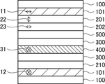
- FIG. 1 is a schematic cross-sectional view of an embodiment of an image display device of the present invention;
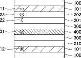
- FIG. 4 is a schematic cross-sectional view of another embodiment of the image display device of the present invention;
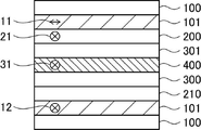
- FIG. 4 is a schematic cross-sectional view of another embodiment of the image display device of the present invention;
- FIG. 4 is a schematic cross-sectional view of another embodiment of the image display device of the present invention;
- FIG. 4 is a schematic cross-sectional view of another embodiment of the image display device of the present invention;
- a numerical range represented by "-" means a range including the numerical values before and after "-" as lower and upper limits.
- parallel, orthogonal, horizontal, and vertical do not mean parallel, orthogonal, horizontal, and vertical in a strict sense, respectively, but within a range of parallel ⁇ 10 °, It means a range of ⁇ 10° orthogonal, ⁇ 10° horizontal, and ⁇ 10° vertical.
- Re( ⁇ ) and Rth( ⁇ ) respectively represent in-plane retardation and thickness direction retardation at wavelength ⁇ . If the wavelength ⁇ of retardation is not specified, the wavelength ⁇ is assumed to be 550 nm.
- the refractive indices nx and ny are the refractive indices in the in-plane direction of the optical member. is the refractive index in the direction perpendicular to the phase axis).
- nz is the refractive index in the thickness direction.
- NAR-4T Abbe refractometer
- DR-M2 manufactured by Atago Co., Ltd.
- the values in the polymer handbook (JOHN WILEY & SONS, INC) and various optical film catalogs can also be used.
- each component may use the substance applicable to each component individually by 1 type, or may use 2 or more types together.
- the content of the component refers to the total content of the substances used in combination unless otherwise specified.
- (meth)acrylate” is a notation representing “acrylate” or “methacrylate”
- (meth)acryl is a notation representing "acrylic” or “methacrylic”
- (Meth)acryloyl” is a notation representing “acryloyl” or “methacryloyl”.
- optical laminate of the present invention has a polarizer, a retardation layer containing a cycloolefin-based polymer film, and an adhesive layer in this order, and the polarizer is provided on at least one side. It has a protective layer.
- at least one side refers to at least one of the surface of the polarizer on the side of the retardation layer and the surface of the polarizer on the side opposite to the retardation layer.
- the optical laminate of the present invention satisfies the following conditions I and III, or conditions II and III. Condition I: An intermediate layer is further provided between the retardation layer and the pressure-sensitive adhesive layer.
- the pressure-sensitive adhesive layer contains an organic low-molecular-weight component with a molecular weight of 500 or less, and the content of the organic low-molecular-weight component with a molecular weight of 500 or less is 2.6% by mass or less, or the retardation layer and the pressure-sensitive adhesive layer is in direct contact with and adhered to the glass substrate via the adhesive layer, and a durability test is performed at 115 ° C. for 100 hours. The content of the molecular component is 50% or less of the content before the durability test.
- Condition III The in-plane retardation Re(550) at a wavelength of 550 nm and the thickness direction retardation Rth(550) of the total retardation layer satisfy the following formulas (1) and (2), respectively. .
- Formula (1) 0 nm ⁇ Re(550) ⁇ 350 nm
- Formula (2) ⁇ 200 nm ⁇ Rth(550) ⁇ 200 nm
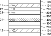
- FIG. 1 shows an example of a configuration diagram of an IPS-type liquid crystal display device that is generally used for vehicle-mounted applications, etc., as a conventional image display device.
- Two polarizers 101 are provided so that the absorption axes (the first polarizer absorption axis 11 and the second polarizer absorption axis 12) are orthogonal to each other so as to sandwich the IPS liquid crystal cell 400 therebetween.
- Reference numeral 31 represents the liquid crystal director direction (liquid crystal alignment direction) of the IPS liquid crystal cell 400 .
- Each of the two polarizers 101 is provided with a protective film 100 on one side.
- the liquid crystal layer ( A first retardation layer) 201 and a cycloolefin-based polymer film (second retardation layer) 202 are provided, and the IPS liquid crystal cell 400 and the cycloolefin-based polymer film (second retardation layer) 202 are They are adhered by an adhesive layer 300 .
- Reference numeral 22 represents the slow axis of the liquid crystal layer (first retardation layer) 201 and reference numeral 23 represents the slow axis of the cycloolefin polymer film (second retardation layer) 202 .
- a low retardation film 210 is provided on the opposite side of the protective film 100 of the other (non-visible side) polarizer 101 of the two polarizers 101, and the IPS liquid crystal cell 400 and the low retardation film 210 are provided.
- the dation film 210 is adhered by the adhesive layer 300 .
- the present inventors have found that the optical laminate in which the retardation layer and the pressure-sensitive adhesive layer are in direct contact, as shown in FIG.
- the content of organic low-molecular components such as AS agent is 2.6% by mass or less, preferably 0.6% by mass or less, more preferably 0.1% by mass or less. It has been found that the use of the adhesive layer 301 improves durability. Further, the present inventors conducted a durability test at 115° C. for 100 hours in a state in which the optical layered body in which the retardation layer and the adhesive layer are in direct contact with each other is adhered to the glass substrate via the adhesive layer.
- the durability is good. I found out. Furthermore, as shown in FIG. was found to be good.
- the retardation layer is not particularly limited as long as it contains a cycloolefin polymer film. Further, the retardation layer may be a cycloolefin polymer film alone, or may have a liquid crystal layer provided adjacent to the cycloolefin polymer film.
- the optical laminate of the present invention has a liquid crystal layer
- the liquid crystal layer present on the polarizer side of the cycloolefin polymer film is regarded as part of the retardation layer
- the cycloolefin polymer film The liquid crystal layer existing on the pressure-sensitive adhesive layer side is regarded as an intermediate layer.
- the liquid crystal layer may be formed using a liquid crystal composition containing a liquid crystalline compound and a compound represented by formula (I) described below.
- the composition preferably contains 0.5 to 7.0% by mass of the compound represented by the formula (I) to be described later with respect to the mass of the liquid crystalline compound.
- an impregnated layer in which the coating layer and the polymer film are mixed may be formed at the interface between the polymer film and the coating layer.
- an impregnated layer in which the coating layer and the polymer film are mixed may be formed at the interface between the polymer film and the coating layer.
- the formation of such an infiltration layer is advantageous for adhesion.
- the polymer film is excessively soaked into the polymer film and the alignment is inhibited, and the alignment is deteriorated, the smaller the soaked layer, the better.
- the permeation layer is preferably as small as possible. It is believed that the cycloolefin-based polymer film and the compound represented by the formula (I) to be described later interact effectively to improve orientation. Furthermore, even when there is an infiltration layer, it is thought that the orientation can be improved in some cases due to local uneven distribution of the compound represented by the formula (I) described later.
- the "penetration layer” in the present invention means a region where both the material of the cycloolefin polymer film and the material of the liquid crystal layer are detected.
- the thickness of the infiltration layer is preferably in the range of 30-300 nm, more preferably in the range of 50-250 nm. Within this range, the adhesion between the liquid crystal layer and the cycloolefin polymer film is good, and the orientation of the liquid crystal layer can be improved.
- the cycloolefin polymer film of the optical laminate of the invention is preferably transparent.
- transparent means that the transmittance of visible light is 60% or more.
- the transmittance is preferably 80% or more, more preferably 90% or more.
- the content of the cycloolefin-based polymer is preferably 60% by mass or more, more preferably 80% by mass or more, relative to the total solid content in the cycloolefin-based polymer film.
- cycloolefin polymers examples include (1) norbornene polymers, (2) monocyclic cycloolefin polymers, (3) cyclic conjugated diene polymers, and (4) vinyl alicyclic hydrocarbon polymers. , and hydrides of (1) to (4).
- Specific examples of the cycloolefin-based polymer include addition (co)polymer cyclopolyolefins containing at least one repeating unit represented by the following general formula (III), and general formula (III) below. Addition (co)polymer cyclopolyolefins further containing at least one repeating unit represented by the following general formula (II) in addition to the repeating unit represented by the following are preferable.
- a ring-opening (co)polymer containing at least one cyclic repeating unit represented by the following general formula (IV) can also be suitably used.
- R 1 to R 6 each represent a hydrogen atom or a hydrocarbon group having 1 to 10 carbon atoms
- X 1 to X 3 and Y 1 to Y 3 each represent a hydrogen atom or a hydrocarbon group having 1 to 10 carbon atoms group, halogen atom, halogen-substituted hydrocarbon group having 1 to 10 carbon atoms, —(CH 2 ) n COOR 11 , —(CH 2 ) n OCOR 12 , —(CH 2 ) n NCO, —(CH 2 ) n NO 2 , —(CH 2 ) n CN, —(CH 2 ) n CONR 13 R 14 , —(CH 2 ) n NR 13 R 14 , —(CH 2 ) n OZ, —(CH 2 ) n W, or (--CO) 2 O or (--CO) 2 NR 15
- R 11 , R 12 , R 13 , R 14 and R 15 each represent a hydrogen atom or a hydrocarbon group having 1 to 20 carbon atoms
- Z represents a hydrocarbon group or a halogen-substituted hydrocarbon group.
- W represents SiR 16 p D 3-p (R 16 is a hydrocarbon group having 1 to 10 carbon atoms, D is a halogen atom, —OCOR 16 or —OR 16 , p is an integer of 0 to 3).
- n represents an integer from 0 to 10.
- the Rth of the optical film is increased and Re is expressed.
- the Rth of the optical film is increased and Re is expressed.
- a film with a high Re-development property can be stretched during the film-forming process to increase the Re value.
- cycloolefin polymer used in the present invention those disclosed in JP-A-10-7732, JP-A-2002-504184, US2004229157A1 or WO2004/070463A1 can also be used. can be done. It is obtained by addition polymerization of norbornene polycyclic unsaturated compounds.
- norbornene-based polycyclic unsaturated compounds and conjugated dienes such as ethylene, propylene, butene, butadiene and isoprene; non-conjugated dienes such as ethylidene norbornene; acrylonitrile, acrylic acid, methacrylic acid, maleic anhydride
- conjugated dienes such as ethylene, propylene, butene, butadiene and isoprene
- non-conjugated dienes such as ethylidene norbornene
- acrylonitrile acrylic acid, methacrylic acid, maleic anhydride
- linear diene compounds such as acids, acrylic acid esters, methacrylic acid esters, maleimide, vinyl acetate and vinyl chloride is also possible.
- a commercial product can also be used as this norbornene-based addition (co)polymer.
- grades with different glass transition temperatures such as APL8008T (Tg70°C), APL6013T (Tg125°C) or APL6015T (Tg145°C) are sold by Mitsui Chemicals, Inc. under the trade name of APEL.
- Tg glass transition temperatures
- APL8008T Tg70°C
- APL6013T Tg125°C
- APL6015T Tg145°C
- Pellets such as TOPAS 8007, TOPAS 6013 and TOPAS 6015 are sold by Polyplastic Co., Ltd.
- Appear 3000 is sold by Ferrania.
- Norbornene-based polymer hydrides JP-A-1-240517, JP-A-7-196736, JP-A-60-26024, JP-A-62-19801, JP-A-2003-1159767 or As disclosed in Japanese Unexamined Patent Application Publication No. 2004-309979, it is possible to use those produced by addition polymerization or metathesis ring-opening polymerization of a polycyclic unsaturated compound followed by hydrogenation.
- R 5 to R 6 in the general formula (IV) are preferably a hydrogen atom or —CH 3
- X 3 and Y 3 in the general formula (IV) are hydrogen Atoms, Cl, —COOCH 3 are preferred, and other groups are selected as appropriate.
- This norbornene-based resin can also be used as a commercially available product. Specifically, JSR Corporation sells it under the trade name of Arton G or Arton F, and Nippon Zeon Co., Ltd. sells Zeonor ) ZF14, ZF16, Zeonex 250 and Zeonex 280 are commercially available, and these can be used.
- the cycloolefin polymer used in the present invention preferably has a mass average molecular weight (Mw) measured by gel permeation chromatography (GPC) of 5,000 to 1,000,000 in terms of polystyrene molecular weight. ,000 to 500,000, more preferably 50,000 to 300,000. Also, the molecular weight distribution (Mw/Mn; Mn is the number average molecular weight measured by GPC) is preferably 10 or less, more preferably 5.0 or less, still more preferably 3.0 or less.
- Mw mass average molecular weight measured by GPC
- the cycloolefin-based polymer used in the present invention preferably has a glass transition temperature (Tg) of 50 to 350°C, more preferably 80 to 330°C, as measured by Differential Scanning Calorimetry (DSC). , more preferably in the range of 100 to 200°C.
- Tg glass transition temperature
- DSC Differential Scanning Calorimetry
- the cycloolefin-based polymer used in the present invention may contain additives within the scope of the present invention.
- the cycloolefin-based polymer film of the optical laminate of the present invention has a water contact angle of 5° to 65° on the surface adjacent to the liquid crystal layer. It is preferably surface-treated to Further, the water contact angle of the polymer film is more preferably 5° to 55°, particularly preferably 5° to 50°.
- the water contact angle refers to a value measured by the following method.
- the water contact angle is measured based on the static drop method of JIS R 3257:1999.
- LSE-ME1 software 2win mini manufactured by Nick Co., Ltd. is used. Specifically, at room temperature of 20° C., pure water is used to drop a droplet of 2 ⁇ L on the surface of a polymer film kept horizontal, and the contact angle is measured 20 seconds after dropping.
- optical properties of cycloolefin polymer film are determined by the following formulas (1) and (2) because the display performance is improved when the optical laminate of the present invention is used in an image display device. preferably satisfies the following formulas (1-1) and (2-1) below, more preferably satisfies the following formulas (1-2) and (2-2) below is more preferred.
- the total optical properties of the retardation layers of the optical layered body of the present invention must satisfy the following formulas (1) and (2), as shown in the above-mentioned condition III, and the following formula (1 -3) and formula (2-3) below, and more preferably satisfy formulas (1-4) and (2-4) below.
- Formula (1) 0 nm ⁇ Re(550) ⁇ 350 nm
- Formula (2) ⁇ 200 nm ⁇ Rth(550) ⁇ 200 nm
- Formula (1-1) 40 nm ⁇ Re(550) ⁇ 200 nm Formula (2-1) 0 nm ⁇ Rth(550) ⁇ 200 nm Formula (1-2) 80 nm ⁇ Re(550) ⁇ 150 nm Formula (2-2) 40 nm ⁇ Rth(550) ⁇ 150 nm
- Formula (1-3) 60 nm ⁇ Re(550) ⁇ 300 nm Formula (2-3) ⁇ 100 nm ⁇ Rth(550) ⁇ 100 nm Formula (1-4) 80 nm ⁇ Re(550) ⁇ 160 nm Formula (2-4) ⁇ 80 nm ⁇ Rth(550) ⁇ 20 nm
- Various properties of the cycloolefin-based polymer film of the retardation layer can be adjusted by stretching. Specifically, the in-plane retardation (Re) and thickness direction retardation ( Rth) and any film thickness can be developed.
- the stretching method is not limited to the above method, but can be realized by a method of stretching not only the in-plane direction but also the thickness direction while heat-treating the laminated heat-shrinkable film disclosed in Patent Document WO10/082620. . Details of general longitudinal stretching and lateral stretching are described below.
- Stretching and relaxation may be combined to adjust properties.
- each process described in (a) to (k) below can be implemented.
- (a) Lateral stretching (b) Longitudinal stretching (c) Lateral stretching ⁇ Relaxing treatment (d) Longitudinal stretching ⁇ Relaxing treatment (e) Longitudinal stretching ⁇ Lateral stretching (f) Longitudinal stretching ⁇ Lateral stretching ⁇ Relaxing treatment (g) Longitudinal stretching ⁇ relaxation treatment ⁇ transverse stretching ⁇ relaxation treatment (h) transverse stretching ⁇ longitudinal stretching ⁇ relaxation treatment (i) transverse stretching ⁇ relaxation treatment ⁇ longitudinal stretching ⁇ relaxation treatment (j) longitudinal stretching ⁇ lateral stretching ⁇ longitudinal stretching (k) longitudinal stretching ⁇ Lateral stretching ⁇ Longitudinal stretching ⁇ Relief treatment
- the transverse stretching step (a) and the longitudinal stretching step (b) are particularly important.
- a plurality of preheating rollers and an upstream stretching roller are used.
- the peripheral speed may be gradually increased toward the downstream based on the temperature change before and after the film comes into contact with each roller, and appropriate tension may be applied between the preheating rollers.
- the film may be rapidly cooled with a cooling roller after longitudinal stretching in order to suppress the occurrence of scratches.
- ⁇ Horizontal stretching> When the cycloolefin polymer film is laterally stretched, it can be stretched in the lateral direction by using, for example, a tenter. That is, both ends of the cycloolefin polymer film in the width direction are gripped with clips, and the film is stretched by expanding the width in the horizontal direction. At this time, the stretching temperature can be controlled by blowing air at a desired temperature into the tenter.
- the "stretching temperature" (hereinafter also referred to as "transverse stretching temperature”) is specified by the surface temperature of the cycloolefin-based polymer film.
- the stretching temperature is preferably controlled to be Tg-40°C to Tg+40°C.
- the transverse stretching temperature in the transverse stretching step is preferably Tg-40°C to Tg+40°C, more preferably Tg-20°C to Tg+20°C, still more preferably Tg-10°C to Tg+10°C.
- the lateral stretching temperature in the lateral stretching step means the average temperature from the stretching start point to the stretching end point.
- the stretching time in the lateral stretching step is preferably 1 second to 10 minutes, more preferably 2 seconds to 5 minutes, and even more preferably 5 seconds to 3 minutes.
- the transverse draw ratio is preferably 1.01 to 4 times, more preferably 1.03 to 3.5 times, and still more preferably 1.1 to 3.0 times.
- a transverse draw ratio of 1.51 to 3.0 is particularly preferred.
- preheating before stretching and heat setting after stretching By performing preheating before stretching and heat setting after stretching, the distribution of Re and Rth after stretching can be reduced, and the variation in orientation angle due to bowing can be reduced. Either preheating or heat setting may be performed, but it is more preferable to perform both. These preheating and heat setting are preferably carried out by gripping with a clip, that is, preferably carried out continuously with stretching.
- Preheating can be carried out at a temperature about 1°C to 50°C higher than the stretching temperature, preferably 2°C to 40°C or less, more preferably 3°C to 30°C or less.
- the preheating time is preferably 1 second or more and 10 minutes or less, more preferably 5 seconds or more and 4 minutes or less, and still more preferably 10 seconds or more and 2 minutes or less.
- “approximately” refers to ⁇ 10% of the width of the unstretched film.
- the heat setting can be performed at a temperature lower than the stretching temperature by 1°C or higher and 50°C or lower, more preferably 2°C or higher and 40°C or lower, further preferably 3°C or higher and 30°C or lower. More preferably, it is not higher than the stretching temperature and not higher than the Tg.
- the preheating time is preferably 1 second or more and 10 minutes or less, more preferably 5 seconds or more and 4 minutes or less, and still more preferably 10 seconds or more and 2 minutes or less. During heat setting, it is preferable to keep the width of the tenter substantially constant.
- the variation in Re and Rth in the width direction and the longitudinal direction can be reduced to 5% or less, more preferably 4% or less, and still more preferably 3% or less.
- a high-speed drawing process may be performed, and the drawing process can be preferably performed at 20 m/min or more, more preferably 25 m/min or more, and still more preferably 30 m/min or more.
- the cycloolefin polymer film has a slow axis parallel to the transport direction.
- the degree of parallelism is to set the angle formed by the conveying direction and the slow axis to 0° ⁇ 8° or less, preferably 0° ⁇ 5° or less, more preferably 0° ⁇ 3° or less, further preferably 0° ° ⁇ 1° or less.
- the thickness of the cycloolefin polymer film is preferably 30 ⁇ m or less, more preferably 5 ⁇ m to 30 ⁇ m, still more preferably 7 ⁇ m to 25 ⁇ m, and particularly preferably 10 ⁇ m to 20 ⁇ m.
- the cycloolefin-based polymer film can be provided with a protective film on the side opposite to the surface to be coated from the viewpoints of preventing blocking during winding and stabilizing transportation. Moreover, it can also be provided on the coating surface side after coating.
- the protective film is peeled off when it is no longer needed, for example, during processing of the polarizing plate.
- As the material of the protective film polyethylene resin, polypropylene resin, polystyrene resin, polyethylene terephthalate resin, etc., which are easy to handle, can be preferably used.
- a layered film can be used as a protective film.
- a self-adhesive protective film that has adhesiveness to a polarizing film by itself is convenient and can be used more preferably because there is no need to protect the adhesive layer on the surface of the protective film.
- Examples of commercially available products of the self-adhesive resin film include Toraytech (manufactured by Toray Industries, Inc.) made of polyethylene resin.
- the target (total retardation layer) that satisfies the condition III described above does not include the protective film.
- the optional liquid crystal layer included in the retardation layer is an optional layer provided adjacent to the cycloolefin-based polymer film described above, and is a liquid crystal layer formed using a liquid crystal composition containing a liquid crystalline compound described below.
- a liquid crystal composition containing a liquid crystalline compound described below.
- the compound represented by formula (I) to be described later is contained in an amount of 0.5 to 7.0% by mass based on the mass of the liquid crystalline compound.
- the description of the liquid crystal layer in this specification also applies to the liquid crystal layer regarded as the intermediate layer, that is, the liquid crystal layer existing on the adhesive layer side of the cycloolefin polymer film.
- the optical properties of the liquid crystal layer are defined by the following formulas (4) and (5) because the display performance is improved when the optical layered body of the present invention is used in an image display device.
- Formula (4) 0 nm ⁇ Re2(550) ⁇ 10 nm
- Formula (5) ⁇ 360 nm ⁇ Rth2(550) ⁇ 50 nm
- Formula (6) 10 nm ⁇ Re2(550) ⁇ 220 nm
- Formula (7) ⁇ 110 nm ⁇ Rth2(550) ⁇ 5 nm
- the optical properties of the liquid crystal layer preferably satisfy the following formulas (4-1) and (5-1), and the following formulas (4-2) and (5) -2) is more preferably satisfied.
- a discotic liquid crystalline compound it preferably satisfies the following formulas (6-1) and (7-1), and satisfies the following formulas (6-2) and (7-2). is more preferred.
- Formula (4-1) 0 nm ⁇ Re2(550) ⁇ 5 nm Formula (5-1) ⁇ 270 nm ⁇ Rth2(550) ⁇ 50 nm Formula (6-1) 20 nm ⁇ Re2(550) ⁇ 200 nm Formula (7-1) ⁇ 100 nm ⁇ Rth2(550) ⁇ 10 nm
- Formula (4-2) 0 nm ⁇ Re2(550) ⁇ 1 nm Formula (5-2) ⁇ 180 nm ⁇ Rth2(550) ⁇ 100 nm Formula (6-2) 60 nm ⁇ Re2(550) ⁇ 160 nm Formula (7-2) ⁇ 80 nm ⁇ Rth2(550) ⁇ 30 nm
- the thickness of the liquid crystal layer is not particularly limited, it is preferably 0.1 ⁇ m to 10 ⁇ m, more preferably 0.3 ⁇ m to 8 ⁇ m, even more preferably 0.5 ⁇ m to 5 ⁇ m.
- the liquid crystal composition forming the liquid crystal layer contains a liquid crystalline compound.
- the liquid crystalline compound is preferably a rod-shaped liquid crystalline compound or a discotic liquid crystalline compound, and is a rod-shaped liquid crystalline compound because the display performance is improved when the optical laminate of the present invention is used in an image display device. is more preferable.
- the total optical properties of the retardation layers of the optical layered body of the present invention must satisfy the following formulas (1) and (2), as shown in the above-mentioned condition III, and the following formula (1 -3) and formula (2-3) below, and more preferably satisfy formulas (1-4) and (2-4) below.
- Formula (1) 0 nm ⁇ Re(550) ⁇ 350 nm
- Formula (2) ⁇ 200 nm ⁇ Rth(550) ⁇ 200 nm
- Formula (1-3) 60 nm ⁇ Re(550) ⁇ 300 nm Formula (2-3) ⁇ 100 nm ⁇ Rth(550) ⁇ 100 nm Formula (1-4) 80 nm ⁇ Re(550) ⁇ 160 nm Formula (2-4) ⁇ 80 nm ⁇ Rth(550) ⁇ 20 nm
- Discotic liquid crystalline compounds include, for example, paragraphs [0025] to [0153] of JP-A-2006-301614, paragraphs [0020] to [0122] of JP-A-2007-108732, and JP-A-2010-244038. Paragraphs [0012] to [0108] of the publication, the contents of which are incorporated herein.
- the liquid crystalline compound is preferably fixed in a vertically aligned state in order to adjust the optical properties of the liquid crystal layer.
- a layer in which a rod-like liquid crystalline compound is fixed in a vertically aligned state can function as a positive C-plate.
- a layer in which a discotic liquid crystalline compound is fixed in a vertically aligned state can function as a negative A-plate.
- vertical alignment refers to the normal direction of the layer and the long axis direction of liquid crystal molecules in the case of a rod-like liquid crystal compound, and the normal direction of the layer and the liquid crystal molecule in the case of a discotic liquid crystal compound.
- This is an orientation state in which the disk planes of are parallel to each other.
- the long axis direction of the liquid crystal molecules and the disc surface of the liquid crystal molecules are parallel to the normal direction of the layer, they may have an inclination depending on the alignment state of the liquid crystal molecules. This inclination is preferably within 3.5°.
- the rod-like liquid crystalline compound when the rod-like liquid crystalline compound is vertically aligned, it is preferable to satisfy the above formulas (4) and (5), and when the discotic liquid crystalline compound is vertically aligned, the above formula (6) and (7) are preferably satisfied.
- the liquid crystal composition forming the liquid crystal layer preferably contains a compound represented by the following formula (I).
- Z represents a substituent having a polymerizable group
- n represents an integer of 0 to 4
- Z of 2 or more may be the same or different.
- Q represents a substituent containing at least one boron atom
- m represents 1 or 2
- two Qs may be the same or different.
- L 100 represents an n+m-valent linking group.
- L 100 is a hydrogen atom, a substituted or unsubstituted alkyl group, a substituted or unsubstituted alkenyl group, a substituted or unsubstituted alkynyl group, a substituted Alternatively, it represents an unsubstituted aryl group, or a substituted or unsubstituted heteroaryl group.
- the substituent having a polymerizable group represented by Z includes, for example, a (meth)acrylate group, a styryl group, a vinyl ketone group, a butadiene group, a vinyl ether group, an oxiranyl group, an aziridinyl group and an oxetane group.
- a substituent containing a (meth)acrylate group, a styryl group, an oxiranyl group or an oxetane group is preferable, and a substituent containing a (meth)acrylate group or a styryl group is more preferable.
- the substituent containing a (meth)acrylate group is preferably a group having an ethylenically unsaturated double bond represented by the following general formula (V).
- R 3 is a hydrogen atom or a methyl group, preferably a hydrogen atom.
- L 1 is a single bond, or -O-, -CO-, -NH-, -CO-NH-, -COO-, -O-COO-, an alkylene group, An arylene group, a heterocyclic group, and a divalent linking group selected from the group consisting of a combination thereof, preferably a single bond, -CO-NH- or -COO-, and a single bond or -CO-NH- is Especially preferred.
- L 100 may be, for example, a divalent linking group such as a single bond, -O-, -CO-, -NH-, -CO-NH-, -COO-, -O-COO-, alkylene divalent linking groups selected from groups, arylene groups, heteroaryl groups, and combinations thereof. Among these, a substituted or unsubstituted arylene group is more preferred.
- alkyl group, alkenyl group, alkynyl group, aryl group and heteroaryl group represented by L 100 have the same meanings as R 1 and R 2 in the following general formula (VI), and the preferred ranges are also the same. Further, examples of substituents possessed by these groups include substituents described in paragraph [0046] of JP-A-2013-054201.
- Q is a substituent containing at least one boron atom, and is preferably a group capable of adsorbing and bonding to the polymer film.
- groups capable of bonding with the hydroxyl groups or carboxyl groups of the polymer film are preferred.
- group capable of adsorbing and bonding to the polymer film means a group capable of chemically adsorbing onto the polymer film by interacting with the structure of the material constituting the polymer film.
- substituents containing at least one boron atom include substituents represented by the following general formula (VI).
- R 1 and R 2 are each independently a hydrogen atom, a substituted or unsubstituted aliphatic hydrocarbon group, a substituted or unsubstituted aryl group, or a substituted or unsubstituted heteroaryl group.
- R 1 and R 2 in general formula (VI) above may form a linking group consisting of an alkylene group, an aryl group, or a combination thereof by linking R 1 and R 2 .
- substituted or unsubstituted aliphatic hydrocarbon groups represented by R 1 and R 2 respectively include substituted or unsubstituted alkyl groups, alkenyl groups and alkynyl groups.
- alkyl groups include methyl group, ethyl group, propyl group, butyl group, pentyl group, hexyl group, heptyl group, octyl group, nonyl group, decyl group, undecyl group, dodecyl group, tridecyl group, hexadecyl group, octadecyl group, eicosyl group, isopropyl group, isobutyl group, sec-butyl group, tert-butyl group, isopentyl group, neopentyl group, 1-methylbutyl group, isohexyl group, 2-methylhexyl group, cyclopentyl group, cycl
- alkenyl groups include linear and branched groups such as vinyl, 1-propenyl, 1-butenyl, 1-methyl-1-propenyl, 1-cyclopentenyl, and 1-cyclohexenyl groups. , or a cyclic alkenyl group.
- alkynyl groups include ethynyl, 1-propynyl, 1-butynyl and 1-octynyl groups.
- aryl group include those in which 1 to 4 benzene rings form a condensed ring, and those in which a benzene ring and an unsaturated five-membered ring form a condensed ring.
- Examples of substituted or unsubstituted heteroaryl groups represented by R 1 and R 2 in general formula (VI) include one heteroatom selected from the group consisting of a nitrogen atom, an oxygen atom and a sulfur atom.
- a heteroaryl group obtained by removing one hydrogen atom from the above heteroaromatic ring is included.
- Specific examples of heteroaromatic rings containing one or more heteroatoms selected from the group consisting of nitrogen, oxygen and sulfur atoms include pyrrole, furan, thiophene, pyrazole, imidazole, triazole, oxazole, isoxazole and oxadiazole.
- thiazole thiadiazole, indole, carbazole, benzofuran, dibenzofuran, thianaphthene, dibenzothiophene, indazole benzimidazole, anthranil, benzisoxazole, benzoxazole, benzothiazole, purine, pyridine, pyridazine, pyrimidine, pyrazine, triazine, quinoline, acridine, isoquinoline, phthalazine, quinazoline, quinoxaline, naphthyridine, phenanthroline, pteridine and the like.
- R 1 and R 2 in general formula (VI) above are preferably hydrogen atoms.
- R 1 and R 2 in general formula (VI) above and L 100 in formula (I) above may be further substituted with one or more substituents if possible.
- These hydrocarbon groups may be substituted with one or more optional substituents. Examples of substituents include monovalent nonmetallic atomic groups excluding hydrogen.
- the molecular weight of the compound represented by the above formula (I) is preferably 120-1200, more preferably 180-800.
- the compound represented by the formula (I) is preferably contained in an amount of 0.5 to 7% by mass, more preferably 1 to 5% by mass, based on the mass of the liquid crystalline compound in the liquid crystal composition. It is more preferable that the content is 3 to 5% by mass. Adhesion can be improved by setting the amount of the compound represented by formula (I) to 0.5% by mass or more, and orientation can be improved by setting the amount to 7% by mass or less. When a plurality of types of liquid crystalline compounds are contained, it is the ratio to the total.
- the compound represented by the above formula (I) is preferably unevenly distributed in the liquid crystal layer in the film thickness direction on the side closer to the polymer film.
- the term "uneven distribution” as used herein refers to uneven distribution as a compound itself, as well as uneven distribution as a reaction product after polymerization when the liquid crystal layer is a polymer of a liquid crystalline composition. It is a concept.
- the liquid crystal layer or the liquid crystal composition forming the liquid crystal layer may contain other additives within the scope of the present invention.
- Other additives include, for example, vertical alignment agents.
- the vertical alignment agent it is preferable to use a pyridinium compound or an onium compound. By containing these compounds, the liquid crystal compound acts as a vertical alignment agent that promotes vertical alignment at the polymer film interface, and the liquid crystal compound It also contributes to the improvement of adhesion at the interface between the liquid crystal layer in which the alignment state is fixed and the polymer film.
- Pyridinium compounds are described, for example, in JP-A-2007-093864 [0030] to [0052], and onium compounds are described, for example, in JP-A-2012-208397 [0027] to [0058]. The contents of these are incorporated herein.
- the liquid crystal layer in which the alignment state of the liquid crystalline compound is fixed may optionally include an air interface side alignment control agent (for example, a copolymer containing a repeating unit having a fluoroaliphatic group) that controls the alignment on the air interface side. ) may be contained.
- an air interface side alignment control agent for example, a copolymer containing a repeating unit having a fluoroaliphatic group
- the liquid crystal composition may contain, for example, a polymerization initiator.
- a polymerization initiator paragraphs [0099] to [0100] of JP-A-2010-84032 and paragraphs [0065] to [0067] of JP-A-2007-219193 can be referred to, and the contents of these can be referred to in the present application. incorporated into the specification.
- Commercially available products include IRGACURE907, 184, 819, TPO, OXE01, OXE02, 127, 2959 (manufactured by BASF), etc. Two or more polymerization initiators may be used in combination.
- the liquid crystal composition may contain a non-liquid crystal polymerizable monomer.
- a compound having a vinyl group, a vinyloxy group, an acryloyl group, or a methacryloyl group is preferable as the polymerizable monomer.
- polyfunctional monomers having two or more polymerizable reactive functional groups such as esters of polyhydric alcohols and (meth)acrylic acid [e.g., ethylene glycol di(meth)acrylate, butanediol di(meth) acrylate, hexanediol di(meth)acrylate, 1,4-cyclohexanediacrylate, pentaerythritol tetra(meth)acrylate], pentaerythritol tri(meth)acrylate, trimethylolpropane tri(meth)acrylate, trimethylolethane tri(meth)acrylate ) acrylate, dipentaerythritol tetra (meth) acrylate, dipentaerythritol penta (meth) acrylate, dipentaerythritol hexa (meth) acrylate, pentaerythritol hexa (meth) acrylate, pent
- this production method In the method for producing a retardation layer having an arbitrary liquid crystal layer (hereinafter also simply referred to as "this production method"), the surface of the cycloolefin polymer film is treated so that the water contact angle is 5 ° to 65 °. and a liquid crystal layer forming step of forming a liquid crystal layer after bringing a liquid crystal composition containing a liquid crystalline compound and a solvent into contact with the surface treated surface. is preferred.
- the surface treatment step included in this production method is a step of treating the surface of the cycloolefin polymer film so that the water contact angle is 5° to 65°.
- the method for measuring the water contact angle is as described above.
- the surface treatment step is preferably a step of adding a hydroxyl group or a carboxyl group to the surface of the cycloolefin polymer film.
- Various known means can be used as specific means, but corona treatment is preferred.
- the corona treatment can be carried out, for example, by the treatment methods described in JP-B-39-12838, JP-A-47-19824, JP-A-48-28067, and JP-A-52-42114. can.
- a corona treatment device a solid state corona treatment machine manufactured by Pillar, a LEPEL type surface treatment machine, a VETAPHON type treatment machine, or the like can be used. Treatment can be carried out at normal pressure in air.
- the gap transparent lance between the electrode and the dielectric roll is 0.1 mm to 10 mm, more preferably 1.0 mm to 2.0 mm.
- the discharge is processed above a dielectric support roller provided in the discharge zone, with a throughput of 10 W ⁇ min/m 2 to 1000 W ⁇ min/m 2 , preferably 20 W ⁇ min/m 2 to 500 W ⁇ min/m 2 . , more preferably 30 W ⁇ min/m 2 to 250 W ⁇ min/m 2 .
- the liquid crystal layer forming step of this manufacturing method is a step of forming a liquid crystal layer after bringing a liquid crystal composition containing a liquid crystalline compound and a solvent into contact with the surface that has been subjected to the surface treatment.
- the method of contacting the liquid crystal composition is not particularly limited, and various known methods such as coating can be used.
- the solvent be a solvent that does not have the ability to dissolve or swell the polymer film.
- the solvent having neither dissolving ability nor swelling ability for the polymer film refers to a solvent having low compatibility with the polymer film, and can be used according to the dissolving ability or swelling ability for the polymer film.
- the solvent capable of dissolving the cycloolefin polymer film is a 24 mm x 36 mm (80 ⁇ m thick) polymer film immersed in a 15 cm 3 bottle containing the solvent at room temperature (25° C.) for 60 seconds. It means a solvent in which the peak area of the polymer film component is 400 mV/sec or more when the immersed solution is analyzed by gel permeation chromatography (GPC).
- the solvent capable of swelling a cycloolefin polymer film is a polymer film measuring 24 mm x 36 mm (thickness 80 ⁇ m) placed vertically in a 15 cm 3 bottle containing the solvent and immersed in the solvent at 25°C for 60 seconds. It means a solvent in which bending or deformation is observed when the bottle is shaken appropriately.
- the polymer film changes in dimension at the swollen portion, and is observed as bending or deformation. No change such as bending or deformation is observed in a solvent with no swelling ability.
- solvents preferably used include methanol, ethanol, cyclohexanone, acetone, methyl isobutyl ketone, methyl acetate, propylene glycol monomethyl ether, propylene glycol monomethyl ether acetate, and toluene. These can be used individually by 1 type or in combination of 2 or more types.
- a solvent has the ability to dissolve or swell a cycloolefin-based polymer film depends not only on the combination of the components of the polymer film and the solvent, but also on the method of manufacturing the cycloolefin-based polymer film. Therefore, it is preferable to select the solvent according to the cycloolefin polymer film. Ester-based solvents such as methyl acetate and ether-based solvents such as propylene glycol monomethyl ether are preferably used because of their excellent balance between the ability to dissolve or swell a cycloolefin polymer film and the stability of dissolution of liquid crystalline compounds. .
- Polarizer included in the optical laminate of the present invention is not particularly limited as long as it is a so-called linear polarizer having a function of converting natural light into specific linearly polarized light.
- the polarizer is not particularly limited, an absorptive polarizer can be used.
- the material of the polarizer used in the present invention is not particularly limited, and commonly used polarizers can be used. Any of the system polarizers can be used.
- the thickness of the polarizer is not particularly limited in the present invention, it is preferably 3 ⁇ m to 60 ⁇ m, more preferably 5 ⁇ m to 30 ⁇ m, even more preferably 5 ⁇ m to 15 ⁇ m.
- An adhesive can be used for laminating the polarizer and the retardation film.
- the thickness of the adhesive layer between the polarizer and the polarizing plate protective films on both sides is preferably about 0.01 to 30 ⁇ m, more preferably 0.01 to 10 ⁇ m, still more preferably 0.05 to 5 ⁇ m. is. If the thickness of the adhesive layer is within this range, no lifting or peeling occurs between the laminated retardation film and the polarizer, and practically acceptable adhesive strength can be obtained.
- polyvinyl alcohol-based resins include vinyl alcohol homopolymer obtained by saponifying polyvinyl acetate, which is a homopolymer of vinyl acetate, vinyl acetate and There are vinyl alcohol copolymers obtained by saponifying copolymers with other polymerizable monomers, and modified polyvinyl alcohol polymers obtained by partially modifying their hydroxyl groups.
- a polyhydric aldehyde, a water-soluble epoxy compound, a melamine compound, a zirconia compound, a zinc compound, a glyoxylate, or the like may be added to this adhesive as a cross-linking agent.
- the thickness of the adhesive layer obtained therefrom is usually 1 ⁇ m or less.
- Another preferred adhesive includes a curable adhesive composition containing a cationically polymerizable compound and a curable adhesive composition containing a radically polymerizable compound, which is cured by irradiation with an active energy ray or by heating.
- cationic polymerizable compounds include compounds having an epoxy group or an oxetanyl group.
- the epoxy compound is not particularly limited as long as it has at least two epoxy groups in the molecule.
- the radically polymerizable compound is not particularly limited as long as it is a radically polymerizable compound having an unsaturated double bond such as a (meth)acryloyl group or a vinyl group.
- Polyfunctional radically polymerizable compounds having polymerizable groups, (meth)acrylates having hydroxyl groups, acrylamides, acryloylmorpholine, etc. may be mentioned, and these compounds may be used alone or in combination.
- compounds described in detail in JP-A-2015-11094 can be used.
- a combination of a radically polymerizable compound and a cationic polymerizable compound can also be used.
- the film is laminated using a laminating roller, dried as necessary, and irradiated with an active energy ray or heated to cure the curable adhesive.
- the light source of the active energy ray is not particularly limited, but an active energy ray having a light emission distribution at a wavelength of 400 nm or less is preferable.
- low pressure mercury lamp, medium pressure mercury lamp, high pressure mercury lamp, ultra high pressure mercury lamp, chemical lamp, black light lamp. , a microwave-excited mercury lamp, a metal halide lamp, and the like are preferably used.
- the retardation film when laminating a retardation film (protective film) and a polarizer with an adhesive, the retardation film has a polarizing Surface treatment (for example, glow discharge treatment, corona discharge treatment, ultraviolet (UV) treatment) or easy adhesion layer formation may be performed on the surface facing the element.
- a polarizing Surface treatment for example, glow discharge treatment, corona discharge treatment, ultraviolet (UV) treatment
- easy adhesion layer formation may be performed on the surface facing the element.
- the materials and forming methods for the easy-adhesion layer described in JP-A-2007-127893, JP-A-2007-127893, etc. can be used.
- the surface of the liquid crystal layer is subjected to glow discharge treatment or corona discharge treatment. It is preferable from the viewpoint of improving the adhesive strength and improving the wettability of the adhesive to the retardation film surface. Furthermore, high adhesiveness can be obtained by preparing a retardation film with the liquid crystal layer in a half-cured state, and fully curing by irradiation with an active energy ray or heating when bonding with a polarizer.
- the optical laminate of the present invention has a protective layer on at least one side of the polarizer.
- the material for the protective layer is not particularly limited, and examples thereof include cellulose acylate films (eg, cellulose triacetate film, cellulose diacetate film, cellulose acetate butyrate film, cellulose acetate propionate film), polymethyl methacrylate, and the like.
- Polyacrylic resin film polyolefin such as polyethylene and polypropylene, polyester resin film such as polyethylene terephthalate and polyethylene naphthalate, polyethersulfone film, polyurethane resin film, polyester film, polycarbonate film, polysulfone film, polyether film, poly Methylpentene film, polyether ketone film, (meth)acrylonitrile film, polyolefin, polymer with alicyclic structure (norbornene resin (Arton: trade name, manufactured by JSR Corporation, amorphous polyolefin (Zeonex: trade name, Japan manufactured by Zeon Corporation)), and the like.
- polyester resin film such as polyethylene terephthalate and polyethylene naphthalate
- polyethersulfone film polyurethane resin film
- polyester film polycarbonate film
- polysulfone film polyether film
- poly Methylpentene film polyether ketone film
- (meth)acrylonitrile film polyolef
- the display performance is improved.
- a low retardation film that satisfies (9) is preferred.
- a pressure-sensitive adhesive or adhesive may be interposed between the polarizer and the protective layer.
- the optical laminate of the present invention has an adhesive layer.
- adhesives contained in the adhesive layer include rubber-based adhesives, acrylic adhesives, silicone-based adhesives, urethane-based adhesives, vinyl alkyl ether-based adhesives, polyvinyl alcohol-based adhesives, and polyvinylpyrrolidone-based adhesives. agents, polyacrylamide-based adhesives, cellulose-based adhesives, and the like.
- acrylic adhesives pressure-sensitive adhesives
- acrylic pressure-sensitive adhesives are preferred from the viewpoint of transparency, weather resistance, heat resistance, and the like.
- a (meth)acrylic polymer is used and usually contains an alkyl (meth)acrylate as a main component as a monomer unit.
- alkyl (meth)acrylate constituting the main skeleton of the (meth)acrylic polymer examples include linear or branched alkyl groups having 1 to 18 carbon atoms. These can be used alone or in combination. The average carbon number of these alkyl groups is preferably 3-9.
- Alkyl (meth)acrylates containing an aromatic ring such as phenoxyethyl (meth)acrylate and benzyl (meth)acrylate can also be used.
- the alkyl (meth) acrylate containing an aromatic ring may be used by mixing a polymer obtained by polymerizing this with the (meth) acrylic polymer exemplified above, or may be used by copolymerizing with the alkyl (meth) acrylate. good too. From the viewpoint of transparency, copolymerization is preferred. Details of the adhesive are described, for example, in [0071]-[0084] of JP-A-2018-60014. The description of the publication is incorporated herein by reference.
- the residual amount of the (meth)acrylic acid ester-based monomer having a cyclic structure in the pressure-sensitive adhesive layer is preferably 100 ppm or less for better durability.
- the method of forming the pressure-sensitive adhesive layer is not particularly limited, but for example, a method of applying a solution of the pressure-sensitive adhesive onto a release sheet, drying it, and then transferring it to the surface of the transparent polymer layer; It can be formed by a method of applying directly to the surface of the layer and drying.
- the adhesive solution is prepared as a solution of about 10 to 40% by mass by dissolving or dispersing the adhesive in a solvent such as toluene or ethyl acetate.
- a roll coating method such as reverse coating or gravure coating, a spin coating method, a screen coating method, a fountain coating method, a dipping method, a spray method, or the like can be employed.
- Materials constituting the release sheet include, for example, synthetic polymer films such as polyethylene, polypropylene, and polyethylene terephthalate; rubber sheets; paper; cloth; mentioned.
- the thickness of the pressure-sensitive adhesive layer is not particularly limited, it is preferably 3 ⁇ m to 50 ⁇ m, more preferably 4 ⁇ m to 50 ⁇ m, and even more preferably 5 ⁇ m to 50 ⁇ m, for better durability. , 5 ⁇ m to 30 ⁇ m.
- the storage elastic modulus of the pressure-sensitive adhesive layer is preferably 0.18 Mpa or more, more preferably 0.45 Mpa or more, and more preferably 2.2 Mpa or more for the reason of better durability. More preferred.
- the storage elastic modulus of the pressure-sensitive adhesive layer is preferably 5 Mpa or less.
- the storage elastic modulus of the pressure-sensitive adhesive layer refers to a value measured by laminating the pressure-sensitive adhesive and using a tensile tester according to the following method.
- a plurality of pressure-sensitive adhesive tapes are laminated and autoclaved at 60° C. ⁇ 0.5 MPa ⁇ 30 minutes to prepare a sample for dynamic viscoelasticity test with a thickness of 1 mm.
- This sample is subjected to a dynamic viscoelasticity test using a tensile tester (shear rheometer (Anton Paar; device name: MCR301) within the linear region at a frequency of 1 Hz.
- the storage elastic modulus is measured at a temperature range of -40°C to +150°C at a heating rate of 3°C/min, and the value at 30°C is read.
- the component analysis of the pressure-sensitive adhesive layer is performed using a headspace gas chromatography mass spectrometer (hereinafter also referred to as "HS-GCMS”) to remove volatile components such as solvents for the reason of better durability.
- HS-GCMS headspace gas chromatography mass spectrometer
- the organic low molecular weight component (molecular weight 32 to 200) constituting the adhesive is preferably 2000 ppm or less, more preferably 1000 ppm or less, further preferably 500 ppm or less, and 100 ppm. The following are particularly preferred.
- the adhesive layer was measured by HS-GCMS after the durability test. 3, if the organic low-molecular-weight component (molecular weight 32 to 200) is 500 ppm or less, the durability is further improved.
- the optical layered body of the present invention has an intermediate layer between the retardation layer and the pressure-sensitive adhesive layer when the condition I described above is satisfied.
- the intermediate layer is preferably an organic intermediate layer or an inorganic intermediate layer that is in direct contact with the retardation layer described above.
- the intermediate layer is preferably an organic intermediate layer provided between the retardation layer and the pressure-sensitive adhesive layer via an adhesive or a pressure-sensitive adhesive, more preferably a polymer film.
- the intermediate layer is preferably transparent.
- transparent means that the visible light transmittance is 60% or more, and in the present invention, the transmittance is preferably 80% or more, and the transmittance is 90% or more. is more preferred.
- the organic intermediate layer in direct contact with the above-described retardation layer blocks or absorbs organic low-molecular-weight components (volatile components) of the pressure-sensitive adhesive layer, There are no particular limitations, and various known ones can be used as long as they work so as not to reach the layers.
- the directly laminated organic intermediate layer includes, for example, a layer obtained by curing a composition containing a polyfunctional monomer, a layer obtained by curing a composition containing a polymer having a functional group, and the like.
- polymer binder a polymer that is simply dried and solidified
- polymer binder a polymer that itself is composed of only a polymer that is not polymerizable. layer.
- polymer binders include, for example, epoxy polymer, diallyl phthalate polymer, silicone polymer, phenol polymer, unsaturated polyester polymer, polyimide polymer, polyurethane polymer, melamine polymer, urea polymer, ionomer polymer, ethylene ethyl acrylate polymer, acrylonitrile acrylate.
- Styrene Copolymer Acrylonitrile Styrene Polymer, Acrylonitrile Chlorinated Polyethylene Styrene Copolymer, Ethylene Acetate Bipolymer, Ethylene Vinyl Alcohol Copolymer, Acrylonitrile Butadiene Styrene Copolymer, Vinyl Chloride Polymer, Chlorinated Polyethylene Polymer, Polyvinylidene Chloride Polymer, Acetic Acid Cellulose polymers, fluoropolymers, polyoxymethylene polymers, polyamide polymers, polyarylate polymers, thermoplastic polyurethane elastomers, polyetheretherketone polymers, polyethersulfone polymers, polyethylene, polypropylene, polycarbonate polymers, polystyrene, polystyrene maleic acid copolymers, Polystyrene acrylic acid copolymer, polyphenylene ether polymer, polyphenylene sulfide polymer, polybutadiene polymer, polybutylene ter
- a directly laminated organic intermediate layer is not particularly limited, and may be, for example, a layer having functions such as a stress relieving layer, a protective layer, an orientation layer, a planarizing layer, and a refractive index adjusting layer.
- the thickness of the directly laminated organic intermediate layer is not particularly limited, it is preferably 0.01 to 50 ⁇ m, more preferably 0.1 to 30 ⁇ m, further preferably more than 0.2 ⁇ m and 10 ⁇ m or less, 0.5 to 5 ⁇ m is particularly preferred.
- the directly laminated inorganic intermediate layer includes a thin layer made of a metal compound (metal compound thin layer) as long as it is transparent.
- a metal compound metal compound thin layer
- Any method can be used as the method for forming the metal compound thin layer as long as it can form the desired thin layer.
- a sputtering method, a vacuum deposition method, an ion plating method, and a plasma CVD (Chemical Vapor Deposition) method are suitable.
- a formation method described in each publication of No. 361774 can be employed.
- the component contained in the metal compound thin layer is not particularly limited as long as it can exhibit an oxygen blocking function, but is selected from, for example, Si, Al, In, Sn, Zn, Ti, Cu, Ce, Ta, etc. 1 Oxides, nitrides or oxynitrides, etc., containing more than one metal can be used. Among these, oxides, nitrides or oxynitrides of metals selected from Si, Al, In, Sn, Zn and Ti are preferred, and metal oxides and nitrides selected from Si, Al, Sn and Ti are particularly preferred. Alternatively, oxynitride is preferable. They may contain other elements as secondary constituents.
- the oxygen barrier layer as the directly laminated inorganic intermediate layer is, for example, US Pat. -12953, as described in JP-A-58-217344, it may be in the form of a laminate of a layer containing the above organic material and a thin metal compound layer, or International Publication 2011/11836. As described in JP-A-2013-248832 and Japanese Patent No. 3855004, the layer may be a hybrid layer of an organic compound and an inorganic compound.
- the thickness of the directly laminated inorganic intermediate layer is not particularly limited, it is preferably 0.01 to 10 ⁇ m, more preferably 0.05 to 5 ⁇ m, even more preferably 0.1 to 2 ⁇ m.
- Organic intermediate layer The organic intermediate layer provided between the retardation layer and the pressure-sensitive adhesive layer via an adhesive or pressure-sensitive adhesive is not particularly limited, and a commonly used polymer film (e.g., polarizer) protective film, etc.) can be used.
- a commonly used polymer film e.g., polarizer
- polymer constituting the polymer film include, for example, cellulose-based polymers; acrylic polymers having acrylic acid ester polymers such as polymethyl methacrylate and lactone ring-containing polymers; thermoplastic norbornene-based polymers; Polymers; polyester polymers such as polyethylene terephthalate and polyethylene naphthalate; styrene polymers such as polystyrene and acrylonitrile-styrene copolymers (AS polymers); polyolefin polymers such as polyethylene, polypropylene and ethylene-propylene copolymers; vinyl chloride amide-based polymer such as nylon and aromatic polyamide; imide-based polymer; sulfone-based polymer; polyethersulfone-based polymer; polyetheretherketone-based polymer; polyphenylene sulfide-based polymer; vinyl butyral-based polymer; arylate-based polymer; polyoxymethylene-based polymer; epoxy-based polymer;
- the polymer constituting the polymer film at least one selected from the group consisting of cycloolefin-based polymer, acrylic polymer, polycarbonate-based polymer, and cellulose-based polymer film from the viewpoint of workability and optical performance. preferably used.
- acrylic polymers include polymethyl methacrylate and lactone ring-containing polymers described in paragraphs [0017] to [0107] of JP-A-2009-98605.
- the polymer film is preferably transparent.
- the thickness d of the organic intermediate layer is preferably 0.5 ⁇ m or more, and more preferably 1 ⁇ m or more, for the reason that the effects of the present invention are more excellent.
- the thickness is preferably 50 ⁇ m or less, more preferably 30 ⁇ m or less, even more preferably 20 ⁇ m or less, particularly preferably 10 ⁇ m or less, and the film manufacturability. Considering the above, it is possible to use up to about 5 to 10 ⁇ m.
- the intermediate layer described above may have optical anisotropy.
- an intermediate layer may be provided between the retardation layer and the adhesive layer via an adhesive having a thickness of 10 ⁇ m or less, and the intermediate layer itself may have optical anisotropy (optical retardation).
- the in-plane retardation Re1 (550) at a wavelength of 550 nm and the thickness direction retardation Rth1 (550) of the total of the retardation layer and the intermediate layer preferably satisfies the following formulas (1) and (2), respectively, and more preferably satisfies the following formulas (1-1) and (2-1), and the following formula ( 1-2) and the following formula (2-2) are more preferably satisfied.
- Formula (1) 0 nm ⁇ Re1(550) ⁇ 350 nm
- Formula (2) ⁇ 200 nm ⁇ Rth1(550) ⁇ 200 nm
- Formula (1-1) 60 nm ⁇ Re1(550) ⁇ 300 nm
- Formula (2-1) ⁇ 100 nm ⁇ Rth1(550) ⁇ 100 nm
- Formula (1-2) 80 nm ⁇ Re1(550) ⁇ 160 nm
- Formula (2-2) ⁇ 80 nm ⁇ Rth1(550) ⁇ 20 nm
- the image display device of the present invention has the above-described optical laminate of the present invention.
- the display element used in the image display device of the present invention is not particularly limited, and examples thereof include liquid crystal cells, organic electroluminescence (hereinafter abbreviated as "EL") display panels, and plasma display panels.
- EL organic electroluminescence
- a liquid crystal cell or an organic EL display panel is preferable, and an organic EL display panel is more preferable.
- the image display device of the present invention is preferably a liquid crystal display device using a liquid crystal cell as a display element, or an organic EL display device using an organic EL display panel as a display element. is more preferred.
- Liquid crystal display device As a liquid crystal display device which is an example of the image display device of the present invention, a liquid crystal having the above-described optical laminate of the present invention (however, the ⁇ /4 plate is not included) and a liquid crystal cell It is a display device.
- the optical layered bodies provided on both sides of the liquid crystal cell, it is preferable to use the optical layered body of the present invention as the polarizing element on the front side (visible side). It is more preferable to use the optical laminate of the present invention as the.
- the liquid crystal cell constituting the liquid crystal display device will be described in detail below.
- liquid crystal cell VA (Vertical Alignment) mode
- OCB Optically Compensated Bend
- IPS In-Plane-Switching
- TN Transmission Nematic
- TN mode liquid crystal cells rod-like liquid crystal molecules (rod-like liquid crystal compounds) are substantially horizontally aligned when no voltage is applied, and are twisted at an angle of 60 to 120°.
- TN mode liquid crystal cells are most commonly used as color TFT liquid crystal display devices, and are described in many documents.
- VA mode liquid crystal cells rod-like liquid crystal molecules are aligned substantially vertically when no voltage is applied.
- VA mode liquid crystal cells include (1) a narrowly defined VA mode liquid crystal cell in which rod-like liquid crystalline molecules are aligned substantially vertically when no voltage is applied and substantially horizontally aligned when voltage is applied (Japanese Unexamined Patent Application Publication No. 2-2002).
- n-ASM Analy symmetrically aligned microcell
- any of PVA (Patterned Vertical Alignment) type, optical alignment type, and PSA (Polymer-Sustained Alignment) type may be used. Details of these modes are described in Japanese Unexamined Patent Application Publication No. 2006-215326 and Japanese National Publication of International Patent Application No. 2008-538819.
- the IPS mode liquid crystal cell rod-like liquid crystal molecules are oriented substantially parallel to the substrate, and the liquid crystal molecules respond planarly by applying an electric field parallel to the substrate surface.
- black display is obtained when no electric field is applied, and the absorption axes of the pair of upper and lower polarizing plates are perpendicular to each other.
- a method of using an optical compensatory sheet to reduce leakage light during black display in an oblique direction and improve the viewing angle is disclosed in Japanese Patent Application Laid-Open Nos. H10-54982, H11-202323, and H9-292522. JP-A-11-133408, JP-A-11-305217 and JP-A-10-307291.
- the IPS mode is most preferable from the viewpoint of viewing angle performance.
- Organic EL display device As an organic EL display device that is an example of the image display device of the present invention, for example, the optical laminate of the present invention described above (provided that the adhesive layer and the ⁇ /4 plate are including) and an organic EL display panel in this order.
- An organic EL display panel is a display panel configured using an organic EL element in which an organic light-emitting layer (organic electroluminescence layer) is sandwiched between electrodes (between a cathode and an anode).
- the configuration of the organic EL display panel is not particularly limited, and a known configuration is adopted. Further, it is more preferable to use a reverse wavelength dispersion liquid crystalline compound as the ⁇ /4 plate excellent in optical performance.
- liquid crystalline compound represented by general formula (II) described in International Publication No. WO2017/043438 is preferably used.
- the descriptions in Examples 1 to 10 of WO2017/043438 and Example 1 of JP-A-2016-91022 can be referred to.
- the coating layer is cured by irradiating ultraviolet rays at 300 mJ/cm 2 to cure the optically anisotropic layer.
- a layer (liquid crystal layer) was formed.
- the produced retardation film had an Re of 124 nm and an Rth of -28 nm.
- first retardation layer the liquid crystal layer included in the produced retardation film
- second retardation layer the cycloolefin-based polymer film
- ATMMT new Pentaerythritol tetraacrylate manufactured by Nakamura Chemical Industry
- Liquid crystalline compound R1 A mixture of 83:15:2 (mass ratio) of the following liquid crystalline compounds (RA) (RB) (RC)
- Surfactant S1 weight average molecular weight: 15000, numerical values in the following structure are % by mass
- Surfactant S2 (weight average molecular weight: 11,200)
- a core layer cellulose acylate dope 1 was prepared by putting the following composition into a mixing tank and stirring to dissolve each component.
- Core layer cellulose acylate dope 1 ⁇ Cellulose acetate having a degree of acetyl substitution of 2.88 100 parts by mass Ester oligomer A below 10 parts Polarizer durability improving agent below 4 parts UV absorber below 2 parts by mass Methylene chloride (first solvent) 430 parts by mass Part Methanol (second solvent) 64 parts by mass ⁇
- Ester oligomer A (weight average molecular weight: 750)
- Outer Layer Cellulose Acylate dope 1 To 90 parts by mass of the above core layer cellulose acylate dope 1 was added 10 parts by mass of the following matting agent solution to prepare outer layer cellulose acylate dope 1 .
- AEROSIL R972 manufactured by Nippon Aerosil Co., Ltd.
- a core layer cellulose acylate dope 2 was prepared by putting the following composition into a mixing tank and stirring to dissolve each component.
- Core layer cellulose acylate dope 2 ⁇ - 100 parts by mass of cellulose acetate having a degree of acetyl substitution of 2.88 - 12 parts by mass of the following polyester - 4 parts by mass of the polarizer durability improver - 430 parts by mass of methylene chloride (first solvent) - 64 parts by mass of methanol (second solvent) Part ⁇
- Polyester (number average molecular weight 800)
- An outer layer cellulose acylate dope 2 was prepared by adding 10 parts by weight of the following matting agent solution to 90 parts by weight of the core layer cellulose acylate dope 2 described above.
- Matting agent solution ⁇
- Silica particles with an average particle size of 20 nm AEROSIL R972, manufactured by Nippon Aerosil Co., Ltd.
- first solvent 76 parts by mass Methanol (second solvent) 11 parts by mass Core layer cellulose acylate dope 1 part by mass ⁇
- cellulose acylate film 2 After filtering the core layer cellulose acylate dope 2 and the outer layer cellulose acylate dope 2 through a filter paper having an average pore size of 34 ⁇ m and a sintered metal filter having an average pore size of 10 ⁇ m, the core layer cellulose acylate dope 2 and the outer layer cellulose on both sides thereof were filtered. Three layers of the acylate dope 2 were simultaneously cast on a drum at 20° C. through a casting port (band casting machine). Next, the film was peeled off with a solvent content of approximately 20% by mass, fixed with tenter clips at both ends in the width direction, and dried while being stretched in the horizontal direction at a draw ratio of 1.1.
- the film was further dried by transporting it between rolls of a heat treatment apparatus, and a cellulose acylate film 2 having a thickness of 40 ⁇ m was produced as a low retardation film 210 .
- the protective film 100 produced above was immersed in a 2.3 mol/L sodium hydroxide aqueous solution at 55° C. for 3 minutes. It was washed in a water washing bath at room temperature and neutralized with 0.05 mol/L sulfuric acid at 30°C. It was again washed in a water washing bath at room temperature and dried with hot air at 100° C. to saponify the surface of the protective film.
- ⁇ Preparation of polarizing plate> The saponified protective film 100 prepared above, the polyvinyl alcohol-based polarizer, and the retardation film prepared above are adjusted so that the absorption axis of the polarizer and the slow axis of the retardation film are parallel to each other.
- As the adhesive a 3% aqueous solution of PVA (PVA-117H manufactured by Kuraray Co., Ltd.) was used.
- the lower polarizing plate was prepared by bonding together the saponified protective film, the polyvinyl alcohol-based polarizer, and the saponified protective film 100 prepared above in the same manner. At this time, the adhesion between the polarizer and the retardation film was practically sufficient.
- Acrylic polymer adhesives were prepared according to the following procedure to obtain adhesives I, II and III.
- Adhesive I organic low molecular weight component with a molecular weight of 500 or less: 2.6% by mass
- Main agent SK Dyne SF-2147
- Crosslinking agent 80 mg
- Silane coupling agent 120 mg
- AS agent (1-octyl-4-methylpyridinium bis (trifluoromethanesulfonyl) imide) 670 mg ⁇
- Adhesive II organic low molecular weight component with a molecular weight of 500 or less: 0.6% by mass
- Main agent SK Dyne SF-2147
- Crosslinking agent 80 mg
- Adhesive III organic low molecular weight component with a molecular weight of 500 or less: 5.5% by mass
- (1-octyl-4-methylpyridinium bis (trifluoromethanesulfonyl) imide) 1670 mg ⁇
- Adhesive IV An acrylic polymer was prepared according to the following procedure. 70 parts by mass of 2-ethylhexyl acrylate, 20 parts by mass of ethyl acrylate, 6 parts by mass of hydroxyethyl methacrylate, 5 parts by mass of benzyl acrylate and acrylic acid 4 parts by mass were polymerized by a solution polymerization method to obtain an acrylic polymer pressure-sensitive adhesive IV having an average molecular weight of 250,000.
- Adhesive V An acrylic polymer was prepared according to the following procedure. 70 parts by weight of 2-ethylhexyl acrylate, 20 parts by weight of ethyl acrylate, 6 parts by weight of hydroxyethyl methacrylate, and 4 parts by weight of acrylic acid were placed in a reaction vessel equipped with a cooling tube, a nitrogen inlet tube, a thermometer, and a stirring device. Polymerization was carried out according to the method to obtain an adhesive V of an acrylic polymer having an average molecular weight of 300,000.
- adhesive sheets were produced according to the following procedure.
- the prepared pressure-sensitive adhesive composition was applied to a PET film surface-treated with a silicone release agent using a die coater and dried at 150°C for 3 hours to prepare a pressure-sensitive adhesive sheet having a pressure-sensitive adhesive layer with a thickness of 15 ⁇ m. did.
- the storage elastic modulus of the adhesive layer was 0.18 MPa.
- ⁇ Adhesives VI and VII> Opteria D692 (thickness: 15 ⁇ m, storage elastic modulus: 2.2 MPa, manufactured by Lintec Corporation) was used as the adhesive VI.
- SK1478 (thickness: 25 ⁇ m, storage elastic modulus: 0.45 MPa, manufactured by Soken Chemical Co., Ltd.) was used as adhesive VII.
- a discharge amount of 125 W ⁇ Corona treatment was applied at min/m 2 .
- an acrylate-based polymer composition 1 having the following composition was applied by a die coating method.
- the coating layer was cured by irradiating ultraviolet rays at 300 mJ/cm 2 to form an acrylate polymer layer 1 .
- the produced optical layered body was evaluated for durability, which will be described later. It was thought that this would be effective in suppressing cracks in cycloolefin by suppressing the migration of the low-molecular-weight components of the adhesive to the cycloolefin side and increasing the rigidity of the cycloolefin polymer.
- the rigidity is defined as an index of elastic modulus x film thickness in terms of mechanical properties.
- a discharge amount of 125 W ⁇ Corona treatment was applied at min/m 2 .
- an acrylate-based polymer composition 2 having the following composition was applied by a die coating method.
- the coating layer was cured by irradiating ultraviolet rays at 300 mJ/cm 2 to form an acrylate polymer layer 2 .
- Example 7-1 [Preparation of Optical Layered Body of Example 7-1]
- the liquid crystal layer forming composition 1 was applied by adjusting the liquid discharge amount of the die coating method (reduced by 6%), dried, and cured by ultraviolet irradiation.
- a first retardation layer is formed, and the following acrylate polymer layer 2-2 (thickness 3 ⁇ m) is directly laminated as an organic intermediate layer on the surface of the adhesive layer side of the second retardation layer.
- an optical laminate was produced under the same conditions as in Example 7.
- a method for forming the acrylate-based polymer layer 2-2 is shown below.
- a discharge amount of 125 W ⁇ Corona treatment was applied at min/m 2 .
- an acrylate-based polymer composition 2-2 having the following composition was applied by a die coating method, adjusting the coating film thickness so that the film thickness after curing by ultraviolet irradiation would be 3 ⁇ m.
- in order to dry the solvent of the composition after heating with warm air of 70° C.
- the coating layer was cured by irradiating ultraviolet rays at 300 mJ/cm 2 to form an acrylate polymer layer 2-2.
- the total retardation including the produced retardation and the intermediate layer was 124 nm for Re and -21 nm for Rth.
- Surfactant S3 (weight average molecular weight: 11000, the numerical values in the following formula indicate the content (mol%) of each repeating unit with respect to all repeating units.
- Example 7-2 [Preparation of Optical Layered Body of Example 7-2]
- Example 7-1 An optical laminate was produced under the same conditions as in the above. A method for forming the acrylate-based polymer layer 2-2 is shown below.
- a discharge amount of 125 W ⁇ Corona treatment was applied at min/m 2 .
- the acrylate-based polymer composition 2-2 having the above composition was applied by a die coating method, adjusting the coating film thickness so that the film thickness after curing by ultraviolet irradiation was 2 ⁇ m.
- in order to dry the solvent of the composition after heating with hot air at 70° C.
- the coated layer was cured by irradiating ultraviolet rays at 300 mJ/cm 2 to form an acrylate polymer layer 2-2.
- the total retardation including the produced retardation and the intermediate layer was 135 nm for Re and -12 nm for Rth.
- Example 7-3 [Preparation of Optical Layered Body of Example 7-3]
- the liquid crystal layer forming composition 1 is applied by adjusting the liquid discharge amount of the die coating method (increased by 25%), dried, and cured by ultraviolet irradiation. to form a first retardation layer, and the following acrylate-based polymer layer 2-2 (thickness 5 ⁇ m) was directly laminated as an organic intermediate layer on the surface of the adhesive layer side of the second retardation layer. Except for this, an optical laminate was produced under the same conditions as in Example 7-2.
- a method for forming the acrylate-based polymer layer 2-2 is shown below.
- a discharge amount of 125 W ⁇ Corona treatment was applied at min/m 2 .
- the acrylate-based polymer composition 2-2 having the above composition was applied by a die coating method, adjusting the coating thickness so that the thickness after curing by ultraviolet irradiation would be 5 ⁇ m.
- in order to dry the solvent of the composition after heating with warm air of 70° C.
- the coating layer was cured by irradiating ultraviolet rays at 300 mJ/cm 2 to form an acrylate polymer layer 2-2.
- the total retardation including the produced retardation and the intermediate layer was 135 nm for Re and -30 nm for Rth.
- Example 8 [Preparation of Optical Layered Body of Example 8]
- the acrylate polymer layer 3 (thickness 1 ⁇ m) was directly laminated as an organic intermediate layer on the adhesive layer side surface of the second retardation layer.
- An optical laminate was produced under the same conditions as in 6. A method for forming the acrylate-based polymer layer 3 will be described below.
- a discharge amount of 125 W ⁇ Corona treatment was applied at min/m 2 .
- an acrylate-based polymer composition 3 having the following composition was applied by a die coating method.
- the coating layer was cured by irradiating ultraviolet rays at 300 mJ/cm 2 to form an acrylate polymer layer 3 .
- Example 9 [Preparation of Optical Layered Body of Example 9]
- the liquid crystal layer forming composition 1 (0.25 ⁇ m) was directly laminated as an organic intermediate layer on the adhesive layer side surface of the second retardation layer.
- the liquid crystal layer forming composition 1 was applied by a die coating method. Next, in order to dry the solvent of the composition, after heating with hot air at 70° C. for 120 seconds, the coating layer was cured by irradiating ultraviolet rays at 300 mJ/cm 2 to form a liquid crystal layer. Next, the produced optical layered body was evaluated for durability, which will be described later. It was thought that this would be effective in suppressing cracks in cycloolefin by suppressing the migration of the low-molecular-weight components of the adhesive to the cycloolefin side and increasing the rigidity of the cycloolefin polymer.
- Example 6 [Preparation of Optical Layered Body of Example 11]
- Example 6 except that a low retardation acrylic film (40 ⁇ m) was applied as an organic intermediate layer using the UV adhesive (film thickness 2 ⁇ m) on the surface of the second retardation layer on the pressure-sensitive adhesive layer side.
- An optical laminate was produced under the same conditions.
- FIG. 4 shows the layer structure of the optical laminate.
- the produced optical laminate was evaluated for durability, which will be described later. As a result, as shown in Table 3 below, it was confirmed that cracks in the surface of the optical laminate were improved.
- FIG. 6 shows the layer structure of the optical laminate.
- reference numeral 21 represents the slow axis of the cycloolefin polymer film (retardation layer).
- FIG. 5 shows the layer structure of the optical laminate.
- the produced optical laminate was evaluated for durability, which will be described later. As a result, as shown in Table 3 below, it was confirmed that cracks in the surface of the optical laminate were improved.
- the liquid crystal layer acrylate polymer
- the liquid crystal layer also serves as an organic intermediate layer, which suppresses the movement of the organic low-molecular-weight components of the adhesive, thereby improving cracks. I thought.
- Re (550) and Rth (550) in total of the retardation layer show the content of the organic low-molecular-weight components and the content of organic low-molecular-weight components having a molecular weight of 32 to 200 or less in the pressure-sensitive adhesive layer before and after the durability test.
- first polarizer absorption axis 12 second polarizer absorption axis 21 slow axis of cycloolefin polymer film (retardation layer) 22 slow axis of liquid crystal layer (first retardation layer) 23 cycloolefin polymer film Slow axis of (second retardation layer) 31 Liquid crystal director direction of IPS liquid crystal cell (liquid crystal alignment direction) 100 protective film 101 polarizer 200 cycloolefin polymer film (retardation layer) 201 liquid crystal layer (first retardation layer) 202 Cycloolefin-based polymer film (second retardation layer) 210 low retardation film (isotropic retardation film) 300 adhesive layer 301 low-molecular weight adhesive layer 302 adhesive or adhesive 400 IPS liquid crystal cell 500 intermediate layer (direct lamination) 501 intermediate layer (film)
Landscapes
- Physics & Mathematics (AREA)
- Chemical & Material Sciences (AREA)
- General Physics & Mathematics (AREA)
- Optics & Photonics (AREA)
- Crystallography & Structural Chemistry (AREA)
- Organic Chemistry (AREA)
- Nonlinear Science (AREA)
- Mathematical Physics (AREA)
- Chemical Kinetics & Catalysis (AREA)
- Engineering & Computer Science (AREA)
- Theoretical Computer Science (AREA)
- Polarising Elements (AREA)
Priority Applications (3)
| Application Number | Priority Date | Filing Date | Title |
|---|---|---|---|
| CN202280010708.8A CN116783519A (zh) | 2021-01-19 | 2022-01-19 | 光学层叠体及图像显示装置 |
| JP2022576714A JPWO2022158482A1 (enExample) | 2021-01-19 | 2022-01-19 | |
| US18/349,649 US20230350118A1 (en) | 2021-01-19 | 2023-07-10 | Optical laminate and image display device |
Applications Claiming Priority (4)
| Application Number | Priority Date | Filing Date | Title |
|---|---|---|---|
| JP2021006428 | 2021-01-19 | ||
| JP2021-006428 | 2021-01-19 | ||
| JP2021-112542 | 2021-07-07 | ||
| JP2021112542 | 2021-07-07 |
Related Child Applications (1)
| Application Number | Title | Priority Date | Filing Date |
|---|---|---|---|
| US18/349,649 Continuation US20230350118A1 (en) | 2021-01-19 | 2023-07-10 | Optical laminate and image display device |
Publications (1)
| Publication Number | Publication Date |
|---|---|
| WO2022158482A1 true WO2022158482A1 (ja) | 2022-07-28 |
Family
ID=82549401
Family Applications (1)
| Application Number | Title | Priority Date | Filing Date |
|---|---|---|---|
| PCT/JP2022/001758 Ceased WO2022158482A1 (ja) | 2021-01-19 | 2022-01-19 | 光学積層体および画像表示装置 |
Country Status (3)
| Country | Link |
|---|---|
| US (1) | US20230350118A1 (enExample) |
| JP (1) | JPWO2022158482A1 (enExample) |
| WO (1) | WO2022158482A1 (enExample) |
Cited By (3)
| Publication number | Priority date | Publication date | Assignee | Title |
|---|---|---|---|---|
| WO2024019161A1 (ja) * | 2022-07-22 | 2024-01-25 | 日東電工株式会社 | 光学積層体 |
| WO2024019160A1 (ja) * | 2022-07-22 | 2024-01-25 | 日東電工株式会社 | 光学積層体及び画像表示装置 |
| WO2025142262A1 (ja) * | 2023-12-27 | 2025-07-03 | 富士フイルム株式会社 | 位相差フィルム、偏光板および画像表示装置 |
Citations (4)
| Publication number | Priority date | Publication date | Assignee | Title |
|---|---|---|---|---|
| JP2004361712A (ja) * | 2003-06-05 | 2004-12-24 | Konica Minolta Opto Inc | 楕円偏光板、楕円偏光板の作製方法及び液晶表示装置 |
| JP2016186618A (ja) * | 2015-03-27 | 2016-10-27 | リンテック株式会社 | 粘着剤層付き光学フィルム |
| WO2017164004A1 (ja) * | 2016-03-22 | 2017-09-28 | 富士フイルム株式会社 | 光学フィルム、偏光板、画像表示装置、光学フィルムの製造方法および偏光板の製造方法 |
| JP2018017891A (ja) * | 2016-07-28 | 2018-02-01 | 富士フイルム株式会社 | 液晶表示装置 |
Family Cites Families (3)
| Publication number | Priority date | Publication date | Assignee | Title |
|---|---|---|---|---|
| EP1541655B1 (en) * | 2002-07-26 | 2012-04-18 | Mitsui Chemicals, Inc. | Adhesive composition and soft packaging material composite film |
| KR100775440B1 (ko) * | 2006-12-20 | 2007-11-12 | 동우신테크 주식회사 | 리세드로네이트 나트륨 헤미펜타히드레이트의 제조방법 |
| JP7681571B2 (ja) * | 2020-03-25 | 2025-05-22 | リンテック株式会社 | 粘着シート、積層体および粘着シートの製造方法 |
-
2022
- 2022-01-19 JP JP2022576714A patent/JPWO2022158482A1/ja active Pending
- 2022-01-19 WO PCT/JP2022/001758 patent/WO2022158482A1/ja not_active Ceased
-
2023
- 2023-07-10 US US18/349,649 patent/US20230350118A1/en active Pending
Patent Citations (4)
| Publication number | Priority date | Publication date | Assignee | Title |
|---|---|---|---|---|
| JP2004361712A (ja) * | 2003-06-05 | 2004-12-24 | Konica Minolta Opto Inc | 楕円偏光板、楕円偏光板の作製方法及び液晶表示装置 |
| JP2016186618A (ja) * | 2015-03-27 | 2016-10-27 | リンテック株式会社 | 粘着剤層付き光学フィルム |
| WO2017164004A1 (ja) * | 2016-03-22 | 2017-09-28 | 富士フイルム株式会社 | 光学フィルム、偏光板、画像表示装置、光学フィルムの製造方法および偏光板の製造方法 |
| JP2018017891A (ja) * | 2016-07-28 | 2018-02-01 | 富士フイルム株式会社 | 液晶表示装置 |
Cited By (3)
| Publication number | Priority date | Publication date | Assignee | Title |
|---|---|---|---|---|
| WO2024019161A1 (ja) * | 2022-07-22 | 2024-01-25 | 日東電工株式会社 | 光学積層体 |
| WO2024019160A1 (ja) * | 2022-07-22 | 2024-01-25 | 日東電工株式会社 | 光学積層体及び画像表示装置 |
| WO2025142262A1 (ja) * | 2023-12-27 | 2025-07-03 | 富士フイルム株式会社 | 位相差フィルム、偏光板および画像表示装置 |
Also Published As
| Publication number | Publication date |
|---|---|
| US20230350118A1 (en) | 2023-11-02 |
| JPWO2022158482A1 (enExample) | 2022-07-28 |
Similar Documents
| Publication | Publication Date | Title |
|---|---|---|
| US10935710B2 (en) | Optical film, polarizing plate, image display device, method for producing optical film, and method for producing polarizing plate | |
| JP7265024B2 (ja) | 液晶組成物、光学異方性層、光学フィルム、偏光板および画像表示装置 | |
| US20230350118A1 (en) | Optical laminate and image display device | |
| CN100392500C (zh) | 液晶显示装置 | |
| JP7182533B2 (ja) | 液晶組成物、光学異方性層、光学フィルム、偏光板および画像表示装置 | |
| JP7386256B2 (ja) | 重合性液晶組成物、硬化物、光学フィルム、偏光板および画像表示装置 | |
| US20200292861A1 (en) | Liquid crystal display device | |
| WO2018207798A1 (ja) | 液晶表示装置 | |
| JP2019095553A (ja) | 光学フィルムの製造方法および、光学フィルム、光学フィルム積層体、偏光板、画像表示装置 | |
| TWI383191B (zh) | 液晶顯示裝置 | |
| JP2014214177A (ja) | 液晶組成物、位相差板、円偏光板、画像表示装置、位相差板の製造方法 | |
| JP2018060152A (ja) | Ipsモード用の偏光板のセット及びそれを用いたipsモード液晶表示装置 | |
| KR20200083567A (ko) | 장척 위상차 필름, 장척 적층체, 화상 표시 장치 | |
| JP2018060150A (ja) | Ipsモード用の偏光板のセット及びそれを用いたipsモード液晶表示装置 | |
| JP6009387B2 (ja) | 位相差フィルム、位相差フィルムの製造方法、偏光板および液晶表示装置 | |
| CN108885369A (zh) | 偏振板组和使用了该偏振板组的ips模式液晶显示装置 | |
| JP6699514B2 (ja) | Ipsモード用の偏光板のセット及びそれを用いたipsモード液晶表示装置 | |
| JP6879883B2 (ja) | 光学フィルムの製造方法、偏光板、および、画像表示装置 | |
| CN116783519A (zh) | 光学层叠体及图像显示装置 | |
| JP6724729B2 (ja) | 偏光板のセット及びそれを用いたipsモード液晶表示装置 | |
| JP2007212492A (ja) | 光学補償フィルム、偏光板、及び液晶表示装置 | |
| JP6699513B2 (ja) | 偏光板のセット及びそれを用いたipsモード液晶表示装置 | |
| CN118575108A (zh) | 光学层叠体、偏振片及图像显示装置 | |
| JP2018060149A (ja) | 偏光板のセット及びそれを用いたipsモード液晶表示装置 | |
| JP2024163263A (ja) | 光学フィルムの製造方法 |
Legal Events
| Date | Code | Title | Description |
|---|---|---|---|
| 121 | Ep: the epo has been informed by wipo that ep was designated in this application |
Ref document number: 22742604 Country of ref document: EP Kind code of ref document: A1 |
|
| ENP | Entry into the national phase |
Ref document number: 2022576714 Country of ref document: JP Kind code of ref document: A |
|
| WWE | Wipo information: entry into national phase |
Ref document number: 202280010708.8 Country of ref document: CN |
|
| NENP | Non-entry into the national phase |
Ref country code: DE |
|
| 122 | Ep: pct application non-entry in european phase |
Ref document number: 22742604 Country of ref document: EP Kind code of ref document: A1 |