WO2022158306A1 - 通信用電線 - Google Patents
通信用電線 Download PDFInfo
- Publication number
- WO2022158306A1 WO2022158306A1 PCT/JP2022/000253 JP2022000253W WO2022158306A1 WO 2022158306 A1 WO2022158306 A1 WO 2022158306A1 JP 2022000253 W JP2022000253 W JP 2022000253W WO 2022158306 A1 WO2022158306 A1 WO 2022158306A1
- Authority
- WO
- WIPO (PCT)
- Prior art keywords
- sheath layer
- magnetic
- magnetic sheath
- mass
- parts
- Prior art date
- Legal status (The legal status is an assumption and is not a legal conclusion. Google has not performed a legal analysis and makes no representation as to the accuracy of the status listed.)
- Ceased
Links
Images

Classifications
-
- H—ELECTRICITY
- H01—ELECTRIC ELEMENTS
- H01B—CABLES; CONDUCTORS; INSULATORS; SELECTION OF MATERIALS FOR THEIR CONDUCTIVE, INSULATING OR DIELECTRIC PROPERTIES
- H01B11/00—Communication cables or conductors
- H01B11/18—Coaxial cables; Analogous cables having more than one inner conductor within a common outer conductor
- H01B11/1895—Particular features or applications
-
- H—ELECTRICITY
- H01—ELECTRIC ELEMENTS
- H01B—CABLES; CONDUCTORS; INSULATORS; SELECTION OF MATERIALS FOR THEIR CONDUCTIVE, INSULATING OR DIELECTRIC PROPERTIES
- H01B3/00—Insulators or insulating bodies characterised by the insulating materials; Selection of materials for their insulating or dielectric properties
- H01B3/18—Insulators or insulating bodies characterised by the insulating materials; Selection of materials for their insulating or dielectric properties mainly consisting of organic substances
- H01B3/30—Insulators or insulating bodies characterised by the insulating materials; Selection of materials for their insulating or dielectric properties mainly consisting of organic substances plastics; resins; waxes
- H01B3/307—Other macromolecular compounds
-
- H—ELECTRICITY
- H01—ELECTRIC ELEMENTS
- H01B—CABLES; CONDUCTORS; INSULATORS; SELECTION OF MATERIALS FOR THEIR CONDUCTIVE, INSULATING OR DIELECTRIC PROPERTIES
- H01B3/00—Insulators or insulating bodies characterised by the insulating materials; Selection of materials for their insulating or dielectric properties
- H01B3/18—Insulators or insulating bodies characterised by the insulating materials; Selection of materials for their insulating or dielectric properties mainly consisting of organic substances
- H01B3/30—Insulators or insulating bodies characterised by the insulating materials; Selection of materials for their insulating or dielectric properties mainly consisting of organic substances plastics; resins; waxes
- H01B3/44—Insulators or insulating bodies characterised by the insulating materials; Selection of materials for their insulating or dielectric properties mainly consisting of organic substances plastics; resins; waxes vinyl resins; acrylic resins
- H01B3/441—Insulators or insulating bodies characterised by the insulating materials; Selection of materials for their insulating or dielectric properties mainly consisting of organic substances plastics; resins; waxes vinyl resins; acrylic resins from alkenes
-
- H—ELECTRICITY
- H05—ELECTRIC TECHNIQUES NOT OTHERWISE PROVIDED FOR
- H05K—PRINTED CIRCUITS; CASINGS OR CONSTRUCTIONAL DETAILS OF ELECTRIC APPARATUS; MANUFACTURE OF ASSEMBLAGES OF ELECTRICAL COMPONENTS
- H05K9/00—Screening of apparatus or components against electric or magnetic fields
- H05K9/0073—Shielding materials
- H05K9/0098—Shielding materials for shielding electrical cables
-
- H—ELECTRICITY
- H01—ELECTRIC ELEMENTS
- H01B—CABLES; CONDUCTORS; INSULATORS; SELECTION OF MATERIALS FOR THEIR CONDUCTIVE, INSULATING OR DIELECTRIC PROPERTIES
- H01B11/00—Communication cables or conductors
- H01B11/02—Cables with twisted pairs or quads
- H01B11/06—Cables with twisted pairs or quads with means for reducing effects of electromagnetic or electrostatic disturbances, e.g. screens
- H01B11/10—Screens specially adapted for reducing interference from external sources
- H01B11/1058—Screens specially adapted for reducing interference from external sources using a coating, e.g. a loaded polymer, ink or print
- H01B11/1083—Screens specially adapted for reducing interference from external sources using a coating, e.g. a loaded polymer, ink or print the coating containing magnetic material
-
- Y—GENERAL TAGGING OF NEW TECHNOLOGICAL DEVELOPMENTS; GENERAL TAGGING OF CROSS-SECTIONAL TECHNOLOGIES SPANNING OVER SEVERAL SECTIONS OF THE IPC; TECHNICAL SUBJECTS COVERED BY FORMER USPC CROSS-REFERENCE ART COLLECTIONS [XRACs] AND DIGESTS
- Y02—TECHNOLOGIES OR APPLICATIONS FOR MITIGATION OR ADAPTATION AGAINST CLIMATE CHANGE
- Y02A—TECHNOLOGIES FOR ADAPTATION TO CLIMATE CHANGE
- Y02A30/00—Adapting or protecting infrastructure or their operation
Definitions
- This disclosure relates to communication wires.
- communication wires used in fields such as automobiles are provided with a shield layer on the outside of the core wire for the purpose of reducing the intrusion of noise from the outside and the emission of noise to the outside.
- a shield layer is a sheath layer that covers the outer periphery of a core wire using a material in which a powdery magnetic material is dispersed in an organic polymer.
- a communication wire provided with a sheath layer containing such a magnetic material is disclosed in Patent Documents 1 and 2, for example.
- the magnetic sheath layer When placing a magnetic sheath layer in which magnetic material powder is dispersed in an organic polymer around the outer circumference of a communication wire, the magnetic sheath layer must contain a large amount of magnetic material in order to obtain sufficiently high noise shielding performance. need to let However, if the magnetic sheath layer contains a large amount of magnetic material, the material structure of the magnetic sheath layer becomes brittle, resulting in low wear resistance. In particular, when a communication wire is used in an environment where it is frequently vibrated while in contact with other members, such as in an automobile, the vibration causes friction between the magnetic sheath layer and other members, causing it to become magnetic due to wear. The surface of the sheath layer may be scraped off. As a result, the noise shielding effect of the magnetic sheath layer is reduced.
- an object is to provide a communication wire including a magnetic sheath layer containing a powdery magnetic material and having high wear resistance.
- a communication wire includes a conductor, an insulating layer covering the outer circumference of the conductor, and a magnetic sheath layer covering the outside of the insulating layer, the magnetic sheath layer comprising an organic polymer, and a magnetic material, wherein the magnetic sheath layer contains 15 parts by mass or more of an acid-modified polymer based on 100 parts by mass of the entire organic polymer, and the magnetic material has an average particle size of 50 ⁇ m or less. It is composed of particles, and the magnetic sheath layer contains 300 parts by mass or more based on 100 parts by mass of the entire organic polymer.
- a communication wire according to the present disclosure includes a magnetic sheath layer that contains a powdery magnetic material and has high wear resistance.
- FIG. 1 is a cross-sectional view showing the configuration of a communication wire according to one embodiment of the present disclosure.
- a communication wire according to the present disclosure includes a conductor, an insulating layer covering the outer circumference of the conductor, and a magnetic sheath layer covering the outside of the insulating layer, the magnetic sheath layer comprising an organic polymer, and a magnetic material, wherein the magnetic sheath layer contains 15 parts by mass or more of an acid-modified polymer based on 100 parts by mass of the entire organic polymer, and the magnetic material has an average particle size of 50 ⁇ m or less. It is composed of particles, and the magnetic sheath layer contains 300 parts by mass or more based on 100 parts by mass of the entire organic polymer.
- the communication wire contains an acid-modified polymer as an organic polymer that constitutes the magnetic sheath layer, and the content of the acid-modified polymer is 15 parts by mass or more based on 100 parts by mass of the entire organic polymer.
- the acid-modified polymer functions as a component that increases the breaking strength of the magnetic sheath layer.
- the magnetic sheath layer contains 300 parts by mass or more of the magnetic material with respect to 100 parts by mass of the organic polymer, as described above, friction with an external member is generated. Coarse resin scraps are less likely to be generated when the magnetic sheath layer is received and worn, so that the noise shielding effect is less likely to deteriorate due to wear.
- the content of the acid-modified polymer in the magnetic sheath layer is preferably 25 parts by mass or less based on 100 parts by mass of the entire organic polymer. Then, in the magnetic sheath layer, an excessive increase in crystallinity due to the inclusion of a large amount of acid-modified polymer can be avoided, and the low-temperature resistance of the magnetic sheath layer can be enhanced.
- the magnetic sheath layer preferably contains an elastomer as the organic polymer in addition to the acid-modified polymer.
- Elastomers have a large elongation at break, and by using them together with an acid-modified polymer as a constituent material of the magnetic sheath layer, the wear resistance of the magnetic sheath layer can be effectively improved.
- the tensile breaking stress of the magnetic sheath layer is preferably 20 MPa or more. Then, since the magnetic sheath layer has a high breaking strength, the resin chips generated when the magnetic sheath layer receives friction between the magnetic sheath layer and an external member become finer, making it easier to obtain high abrasion resistance.
- the elongation at break of the magnetic sheath layer is preferably 80% or less. Materials containing an organic polymer tend to have lower breaking strength as the breaking elongation of the material becomes larger. By suppressing the breaking elongation of the magnetic sheath layer to 80% or less, high breaking strength can be ensured. . In this way, by suppressing the breaking elongation of the magnetic sheath layer so that it does not become too large, the effect of miniaturizing the resin waste generated during wear and improving the wear resistance is enhanced.
- the elongation at break of the magnetic sheath layer is preferably 55% or more. If the breaking elongation of the magnetic sheath layer is reduced by adding a large amount of an acid-modified polymer to the magnetic sheath layer, the low-temperature resistance of the magnetic sheath layer tends to be lowered. , the low-temperature resistance of the magnetic sheath layer can be maintained at a high level.
- the communication wire may be configured as a coaxial wire having a metal shield layer on the outer periphery of the insulating layer, and the magnetic sheath layer may be provided on the outer periphery of the metal shield layer.
- a communication wire configured as a coaxial wire is susceptible to noise, but even when a large amount of magnetic material is added to the magnetic sheath layer for the purpose of noise reduction, the magnetic sheath layer has high wear resistance.
- the coaxial cable can be used for communication while suppressing deterioration of noise shielding properties due to wear and reducing the influence of noise.
- FIG. 1 shows a cross-sectional view of a communication wire 1 according to an embodiment of the present disclosure, cut perpendicularly to the axial direction.
- the communication wire 1 is configured as a coaxial wire.
- the communication wire 1 includes a core wire 4 having a conductor 2 and an insulating layer 3 covering the outer circumference of the conductor 2 .
- a metal foil 5 and a braided layer 6 formed by braiding metal wires are provided as a metal shield layer 7 around the outer circumference of the core wire 4 .
- a metal foil 5 covers the outer circumference of the core wire 4 , and further coats the outer circumference of the metal foil 5 to form a braided layer 6 .
- a magnetic sheath layer 8 containing a magnetic material is provided around the metal shield layer 7 .
- an outer sheath layer 9 containing no magnetic material is provided around the outer periphery of the magnetic sheath layer 8 .
- the magnetic sheath layer 8 contains a predetermined amount or more of acid-modified polymer, as will be described in detail later. Also, the grain size and content of the magnetic material contained in the magnetic sheath layer 8 are specified. Since the magnetic sheath layer 8 has such a component composition, even if the magnetic sheath layer 8 is subjected to friction with an external member, coarse resin scraps are less likely to be generated due to wear. Easy to maintain noise shielding performance.
- the communication wire 1 as described above which is configured as a coaxial wire having a metal shield layer 7 and a magnetic sheath layer 8 on the outer periphery of the core wire 4, is suitable for transmitting signals in a high frequency range of 1 GHz or higher.
- the communication wire according to the present disclosure is not limited to having the above structure as long as the outer side of the core wire 4 is covered and the magnetic sheath layer 8 is provided.
- An appropriate configuration may be adopted.
- the magnetic sheath layer 8 may cover the outer circumference of the core wire 4 directly, or may cover the outer circumference of the core wire 4 with another layer interposed like the metal shield layer 7 described above. good too.
- a single insulated wire is used as the core wire 4, but a plurality of insulated wires may be used.
- the core wire 4 can be configured such that a pair of insulated wires are twisted together or run in parallel to transmit a differential signal. If the influence of noise is not so great, only one of the metal foil 5 and the braided layer 6 may be arranged as the metal shield layer 7, or the metal shield layer 7 may be omitted. good too.
- the metal shield layer 7 a form other than the metal foil 5 and the braided layer 6, such as a horizontally wound wire, may be used.
- the outer sheath layer 9 may also be omitted if the function such as protection of the magnetic sheath layer 8 is not so required.
- each of the layers described above is formed in direct contact with the outer periphery of the inner constituent layer, but the communication wire may appropriately include constituent layers other than the layers described above. There may be.
- each constituent member of the coaxial communication wire 1 illustrated above will be described in detail.
- the core wire 4 is a signal wire responsible for transmission of electrical signals in the communication wire 1 and has a conductor 2 and an insulating layer 3 covering the outer periphery of the conductor 2 .
- the materials forming the conductor 2 and the insulating layer 3 are not particularly limited.
- the conductor 2 may be configured as a single wire, it is preferably configured as a stranded wire in which a plurality of strands (for example, seven wires) are twisted together from the viewpoint of enhancing flexibility when bending. In this case, after twisting the strands, compression molding may be performed to form a compressed stranded wire.
- the conductor 2 is configured as a stranded wire, all of them may be made of the same wire, or two or more kinds of wire may be included.
- the diameter of the conductor 2 is not particularly limited.
- the conductor cross-sectional area can be exemplified in the range of 0.05 mm 2 or more and 1.0 mm 2 or less.
- the insulating layer 3 insulates the conductor 2 in the core wire 4 and contains an organic polymer.
- the type of organic polymer is not particularly limited, but examples include olefin polymers such as polyolefins and olefin copolymers, halogen polymers such as polyvinyl chloride, various engineering plastics, elastomers, and rubbers. .
- the organic polymers may be used singly or in combination of two or more by mixing, laminating, or the like.
- the organic polymer may be crosslinked or foamed.
- the insulating layer 3 includes a non-polar organic polymer such as polyolefin such as polypropylene (PP).
- polyolefin such as polypropylene (PP).
- PP polypropylene
- homopolyolefin such as homo PP may be used, or block polyolefin such as block PP may be used.
- the insulating layer 3 may contain additives as appropriate in addition to the organic polymer.
- additives include flame retardants such as metal hydroxides, copper damage inhibitors, hindered phenol-based and sulfur-based antioxidants, and metal oxides such as zinc oxide.
- flame retardants such as metal hydroxides, copper damage inhibitors, hindered phenol-based and sulfur-based antioxidants, and metal oxides such as zinc oxide.
- the insulating layer 3 does not contain an additive made of a magnetic material such as that contained in the magnetic sheath layer 8 .
- the metal shield layer 7 is provided between the core wire 4 and the magnetic sheath layer 8, and has a two-layer structure in which the metal foil 5 and the braided layer 6 are laminated.
- the metal foil 5 is configured as a thin film of a metal material.
- the type of metal forming the metal foil 5 is not particularly limited, and examples thereof include copper, copper alloys, aluminum, aluminum alloys, and the like.
- the metal foil 5 may be composed of a single kind of metal, or may be a laminate of layers of two or more kinds of metals.
- the metal foil 5 may be formed of an independent metal thin film, or may be formed by bonding a metal layer to a base material such as a polymer film by vapor deposition, plating, adhesion, or the like. From the viewpoint of enhancing noise shielding properties, it is preferable to arrange the metal foil 5 in a tandem manner with respect to the core wire 4 .
- the braided layer 6 is configured as a braided body in which a plurality of metal wires are woven together to form a hollow tubular shape.
- the metal wires forming the braided layer 6 include metal materials such as copper, copper alloys, aluminum, and aluminum alloys, and metal materials whose surfaces are plated with tin or the like.
- the metal shield layer 7 constitutes an outer conductor in the coaxial cable structure, and plays a role of shielding noise entering the core wire 4 and noise emitted from the core wire 4 .
- the noise shielding effect is also exhibited by the magnetic sheath layer 8.
- the influence of noise tends to become serious, and by providing the metal shield layer 7 together with the magnetic sheath layer 8, the influence of noise can be effectively reduced.
- the noise shielding effect can be enhanced.
- the order of lamination of the metal foil 5 and the braided layer 6 is not particularly limited, it is preferable to arrange the metal foil 5 inside and the braided layer 6 outside for reasons such as reducing signal loss.
- the magnetic sheath layer 8 covers the outer circumference of the core wire 4 .
- the magnetic sheath layer 8 covers the outer periphery of the core wire 4 with the metal shield layer 7 interposed therebetween.
- the magnetic sheath layer 8 contains a powdery magnetic material and an organic polymer component.
- the magnetic material powder is dispersed in a matrix composed of organic polymer components.
- the magnetic material contained in the magnetic sheath layer 8 is preferably a ferromagnetic material, more preferably a metal or metal compound having soft magnetism.
- the magnetic loss in the magnetic material contained in the magnetic sheath layer 8 absorbs and attenuates high-frequency electromagnetic waves that can cause noise.
- the noise shielding effect is exhibited also by the metal foil 5 and the braided layer 6, but when the communication wire 1 is used for communication in a high frequency range such as 1 GHz or higher, the influence of noise is large. It is likely to become serious, and by providing the magnetic sheath layer 8 together with the metal foil 5 and the braided layer 6, the influence of noise can be effectively reduced.
- Magnetic materials Iron pure iron or iron containing a small amount of carbon
- Fe—Si alloy silicon steel
- Fe—Si Magnetic stainless steel such as -Al alloy (sendust), Fe--Cr--Al--Si alloy, Fe--Si--Cr alloy, Fe--Ni system alloy (permalloy), ferrite and the like can be exemplified.
- ferrite it is particularly preferable to use ferrite because of its excellent noise shielding properties and low cost.
- a Ni--Zn-based ferrite can be particularly suitably used.
- the magnetic materials may be used singly or in combination of two or more by mixing or the like.
- the particles of the magnetic material contained in the magnetic sheath layer 8 have an average particle size (D50 value of equivalent circle diameter in electron microscope observation) of 50 ⁇ m or less. If the particle size of the magnetic material is too large, the structure of the composite material, in which the magnetic material is dispersed in the organic polymer component, becomes brittle, and the magnetic material, together with the organic polymer component, becomes coarse resin waste (including the magnetic material). It is likely to form a powder of organic polymer) and be scraped off from the magnetic sheath layer 8 . However, by suppressing the average particle size of the magnetic material to 50 ⁇ m or less, the affinity between the magnetic material and the organic polymer component increases, and the adhesive force between the magnetic material and the organic polymer component increases.
- a magnetic material having an average particle diameter of 50 ⁇ m or less exhibits excellent noise shielding effects.
- the average particle diameter of the magnetic material is preferably 45 ⁇ m or less, more preferably 30 ⁇ m or less.
- the magnetic material is preferably dispersed in the organic polymer component without forming secondary particles due to aggregation or the like. The diameter is also preferably equal to or less than the above upper limit.
- the average particle diameter of the magnetic material is 0.1 ⁇ m. It is preferable to set the thickness to 0.5 ⁇ m or more.
- the particle shape of the magnetic material is also not particularly limited, and particles of spherical, flat, irregular shape, or the like can be used.
- the content of the magnetic material in the magnetic sheath layer 8 is 300 parts by mass or more when the total organic polymer component is 100 parts by mass. By containing 300 parts by mass or more of the magnetic material with respect to 100 parts by mass of the organic polymer component, the magnetic sheath layer 8 exhibits high noise shielding performance. It is more preferable that the content of the magnetic material is 350 parts by mass or more in order to enhance the noise shielding performance of the magnetic sheath layer 8 . Since the magnetic sheath layer 8 contains a large amount of magnetic material, when it is subjected to friction with an external member, coarse resin scraps are likely to be generated due to wear.
- the magnetic sheath layer 8 contains 300 parts by mass or more of the magnetic material because the average particle diameter is suppressed to 50 ⁇ m or less and the organic polymer component contains a predetermined amount or more of the acid-modified polymer as described below. Even if it is contained, generation of resin waste is suppressed, and the generated resin waste becomes fine.
- the content of each constituent component of the magnetic sheath layer 8 in units of parts by mass is expressed as 100 parts by mass of the entire organic polymer component.
- the upper limit of the magnetic material content is not particularly limited. However, the content is preferably 800 parts by mass or less. Then, it becomes easy to exhibit the properties of the organic polymer component, such as the effect of miniaturizing the resin scraps and the mechanical strength, as the properties of the magnetic sheath layer 8 as a whole.
- the material forming the magnetic sheath layer 8 contains an organic polymer.
- the organic polymer includes at least an acid-modified polymer.
- the content of the acid-modified polymer is 15 parts by mass or more based on 100 parts by mass of the entire organic polymer component.
- the magnetic sheath layer 8 contains an acid-modified polymer, and the content of the acid-modified polymer is 15 parts by mass or more. Coarse resin scraps are less likely to occur. The reason is as follows. First, the acid-modified polymer has high breaking strength as a characteristic of the material itself, has high affinity with the magnetic material due to its polarity, and exhibits high adhesiveness at the interface with the magnetic material particles. , it becomes a material that effectively increases the breaking strength of the magnetic sheath layer 8 . Since the magnetic sheath layer 8 has a high breaking strength, even if the magnetic sheath layer 8 receives friction with an external member, the magnetic sheath layer 8 is less likely to be scraped off due to wear.
- the high breaking strength of the magnetic sheath layer 8 allows the resin debris generated by abrasion to be torn off in a fine state and separated from the magnetic sheath layer 8 without being stretched to a large extent. . These mechanisms make it difficult for coarse resin waste to be generated due to wear. From the viewpoint of further enhancing these effects, the content of the acid-modified polymer in the magnetic sheath layer 8 is more preferably 20 parts by mass or more.
- the upper limit of the acid-modified polymer content in the magnetic sheath layer 8 is not particularly limited. However, since the acid-modified polymer has a higher degree of crystallinity than an organic polymer having a large elongation at break, such as an elastomer to be described later, if a large amount of the acid-modified polymer is contained in the magnetic sheath layer 8, the magnetic sheath layer 8 cannot be formed in a low-temperature environment. characteristics may be degraded. Therefore, from the viewpoint of ensuring the low-temperature resistance of the magnetic sheath layer 8 and suppressing the occurrence of damage such as cracks in a low-temperature environment, the content of the acid-modified polymer is preferably suppressed to 25 parts by mass or less.
- acid-modified polyolefins such as acid-modified polypropylene can be suitably used.
- type of acid modification maleic acid modification, maleic anhydride modification, and the like can be applied.
- acid-modified polymer those having a tensile breaking stress of 20 MPa or more and 50 MPa or less and those having a breaking elongation of 10% or more and 200% or less can be preferably used.
- the tensile breaking stress and breaking elongation of the polymer composition can be evaluated by a tensile test according to JIS K 7161.
- the acid-modified polymer only one type may be used, or two or more types may be used in combination.
- the type of organic polymer contained in the magnetic sheath layer 8 other than the acid-modified polymer is not particularly limited. , elastomers, rubbers and the like can be used. As the organic polymer other than the acid-modified polymer, only one type may be used, or two or more types may be used in combination.
- the organic polymer other than the acid-modified polymer contained in the magnetic sheath layer 8 it is preferable to use a polymer having a breaking elongation greater than that of the acid-modified polymer.
- An elastomer can be preferably used as the organic polymer having a large elongation at break.
- the type of elastomer is not particularly limited, and various thermoplastic elastomers such as olefin-based, styrene-based, vinyl chloride-based, urethane-based, and ester-based elastomers can be applied. Among them, it is particularly preferred to use olefinic thermoplastic elastomers (TPO).
- TPO olefinic thermoplastic elastomers
- the elastomer contained in the magnetic sheath layer 8 preferably has an elongation at break of 200% or more and 1100% or less.
- the content of the elastomer is preferably 45 parts by mass or more in 100 parts by mass of the organic polymer component, from the viewpoint of sufficiently obtaining the effect of containing the elastomer.
- the content of the elastomer should be suppressed to 60 parts by mass or less. In particular, it is preferable to use two or more different elastomers in combination.
- a first elastomer having a breaking elongation of 200% or more and 400% or less and a second elastomer having a breaking elongation of 900% or more and 1100% or less are used, and 100 parts of the organic polymer component is used.
- 30 parts or less of the first elastomer should be blended, and the second elastomer should be blended in an amount equal to or less than that of the first elastomer.
- an organic polymer other than the acid-modified polymer contained in the magnetic sheath layer 8 it is also preferable to use an unmodified polyolefin in addition to the elastomer.
- an unmodified polyolefin By using an unmodified polyolefin, the fluidity of the resin is improved and the effect of improving the extrusion moldability can be obtained.
- Polypropylene or the like can be suitably used as the unmodified polyolefin.
- Unmodified polyolefins may be homopolyolefins or block polyolefins.
- the content of the unmodified polyolefin in the magnetic sheath layer 8 is preferably 10 parts by mass or more and 50 parts by mass or less based on 100 parts by mass of the organic polymer component.
- the magnetic sheath layer 8 may contain additives as appropriate in addition to the magnetic material and the organic polymer.
- additives include flame retardants, copper damage inhibitors, antioxidants, metal oxides, and the like. However, it is preferable that the average particle size of these additives is suppressed to 50 ⁇ m or less as in the case of the magnetic material.
- the thickness of the magnetic sheath layer 8 is not particularly limited, it is preferably 0.10 mm or more from the viewpoint of sufficiently enhancing the noise shielding effect and wear resistance. On the other hand, the thickness of the magnetic sheath layer 8 is preferably 0.50 mm or less from the viewpoint of ensuring bending flexibility.
- the magnetic sheath layer 8 contains an acid-modified polymer as an organic polymer component, and the content of the acid-modified polymer is 15 parts per 100 parts by mass of the organic polymer component.
- the amount By setting the amount to 300 parts by mass or more, a high breaking strength can be obtained even if the magnetic material is contained in an amount of 300 parts by mass or more. Since the magnetic sheath layer 8 has a high breaking strength, even if the magnetic sheath layer 8 is subjected to friction with an external member, the surface of the magnetic sheath layer 8 is less likely to be scraped off due to wear. Also, even if abrasion occurs, the resin chips generated by the abrasion tend to be fine. Refinement of the resin waste is also promoted by keeping the average particle size of the magnetic material forming the magnetic sheath layer 8 to 50 ⁇ m or less.
- Coarse resin scraps are generated by abrasion, and if they separate from the magnetic sheath layer 8, the noise shielding performance may be locally deteriorated in places where the magnetic sheath layer 8 is scraped off as resin scraps. If the resin waste to be generated is fine, such a local deterioration of the noise shielding performance is less likely to occur. Further, even if the surface of the magnetic sheath layer 8 is scraped by wear to form recesses, if the resin waste generated by the wear is fine, the generated resin waste will enter the recesses, They are densely integrated so as to fill the recesses.
- the noise shielding property is maintained by the accumulation of the resin waste in the concave portion. Highly effective. If the generated resin shavings are coarse, they cannot fit into the recesses so as to closely close the recesses, unlike the case where they are fine, so they do not effectively contribute to maintaining the noise shielding property. .
- the abrasion resistance of the magnetic sheath layer 8 can be improved by using an organic polymer component having a high breaking strength as the organic polymer component constituting the magnetic sheath layer 8, as described above. It can also be achieved by using a material having a large elongation at break.
- the improvement of wear resistance due to the improvement of breaking strength is achieved by suppressing the wear itself and miniaturizing the resin waste generated at the time of wear, while the improvement of wear resistance due to the improvement of breaking elongation is achieved. , is achieved by keeping resin scraps in the process of generation in a state of being connected to the magnetic sheath layer 8 without being separated from the magnetic sheath layer 8 .
- the elongation at break of the organic polymer component increases, and the resin scraps in the process of being generated are dragged and stretched in the process of friction, so that they become rather coarse.
- the coarse resin shavings are unlikely to densely fill the concave portions caused by abrasion, and the noise shielding performance is reduced by abrasion. does not effectively contribute to the suppression of
- the improvement in wear resistance due to the improvement in breaking strength of the organic polymer component and the improvement in wear resistance due to the improvement in breaking elongation form different states on the surface of the magnetic sheath layer 8 by different mechanisms.
- the improvement in elongation at break does not contribute to the miniaturization of resin scraps, which is effective in suppressing deterioration of noise shielding properties.
- organic polymers with high breaking elongation tend to have low breaking strength.
- 15 parts by mass or more of the acid-modified polymer is contained in 100 parts by mass of the organic polymer component, so that the elastomer or the like is relatively high.
- the magnetic sheath layer 8 as a whole has a high breaking strength in exchange for a suppressed breaking elongation. It is highly effective in improving the wear resistance of Even if the communication wire 1 according to the present embodiment is subjected to friction while in contact with other members, the deterioration of noise shielding performance due to wear of the magnetic sheath layer 8 is unlikely to occur. Suitable for use in environments subject to frequent vibrations while in contact.
- the low-temperature resistance of the magnetic sheath layer 8 can be maintained at a high level, as described above.
- the communication wire 1 is used in an automobile, it is expected that the communication wire 1 will be exposed to a low-temperature environment, so it is preferable to increase the low-temperature resistance as well as the wear resistance.
- the communication wire 1 of the present disclosure does not necessarily have high low-temperature resistance characteristics, and may not be provided if the use in a low-temperature environment is not assumed.
- the rupture strength of the material can be evaluated by the tensile rupture stress, and from the viewpoint of obtaining high effects of suppressing wear and miniaturizing resin waste in the magnetic sheath layer 8, the tensile rupture stress of the magnetic sheath layer 8 as a whole is is preferably 20 MPa or more, more preferably 24 MPa or more. On the other hand, from the viewpoint of suppressing deterioration in low-temperature resistance properties due to the inclusion of a large amount of components that increase the tensile breaking stress, such as acid-modified polymers, the tensile breaking stress of the magnetic sheath layer 8 as a whole is preferably 28 MPa or less.
- an organic polymer having a large elongation at break such as an elastomer component, does not contribute to miniaturization of the resin waste generated during wear in the magnetic sheath layer 8, but rather causes the resin waste to become coarse. It contributes to suppression of wear of the magnetic sheath layer 8 by a mechanism different from that of the acid-modified polymer.
- the organic polymer having a large elongation at break compensates for the deterioration of the low temperature resistance due to the inclusion of the acid-modified polymer, and contributes to the improvement of the low temperature resistance.
- the magnetic sheath layer 8 of the present embodiment 15 parts by mass or more of the 100 parts by mass of the organic polymer component is the acid-modified polymer, so that the contents of the other components are relatively limited.
- an organic polymer having a large breaking elongation such as an elastomer component as another component, the magnetic sheath layer 8 is likely to effectively achieve both high wear resistance and high low temperature resistance.
- the elongation at break of the magnetic sheath layer 8 as a whole is preferably 55% or more.
- the breaking elongation of the magnetic sheath layer 8 as a whole should be 80% or less, or even 75% or less. % or less.
- the outer sheath layer 9 is a layer provided to cover the outer periphery of the magnetic sheath layer 8 and is exposed to the outer periphery of the communication wire 1 as a whole.
- the outer sheath layer 9 contains no magnetic material except for inevitable impurities.
- the outer sheath layer 9 plays a role of physically protecting the magnetic sheath layer 8 and the constituent members further inside from contact with external objects.
- the magnetic sheath layer 8 is designed to reduce noise shielding performance even when it comes into contact with an external object by miniaturizing the resin waste generated by abrasion by setting the component composition. Therefore, from the viewpoint of sufficiently suppressing the wear of the magnetic sheath layer 8, the outer sheath layer 9 may not necessarily be provided.
- the magnetic sheath layer 8 is less likely to be worn, making it easier to maintain a higher level of noise shielding performance.
- the inclusion of the magnetic material increases the hardness and may cause damage such as cracks and cracks to occur easily, but the magnetic sheath layer 8 is covered with the outer sheath layer 9. Therefore, even if the magnetic sheath layer 8 is damaged such as a crack or fracture, it is possible to prevent the damage from progressing and leading to the formation of large voids. Then, as the damage progresses, voids are formed on the surface of the magnetic sheath layer 8, and electromagnetic waves leak through the voids, thereby reducing the noise shielding performance of the magnetic sheath layer 8.
- the outer sheath layer 9 preferably contains an organic polymer.
- organic polymers include olefin polymers such as polyolefins and olefin copolymers, halogen polymers such as polyvinyl chloride, and various engineering plastics, similar to the organic polymers forming the insulating layer 3 and the magnetic sheath layer 8. , elastomers, rubbers, and the like. Among them, it is preferable to use an olefin-based polymer, particularly TPO, because of its excellent insulating properties and heat resistance.
- the organic polymers may be used singly or in combination of two or more by mixing, laminating, or the like.
- the organic polymer may be crosslinked or foamed.
- the same organic polymer as at least a part of the organic polymers constituting the magnetic sheath layer 8 is also used in the outer sheath layer 9.
- the outer sheath layer 9 may also contain the same type of elastomer as that contained in the magnetic sheath layer 8 .
- the thickness of the outer sheath layer 9 is not particularly limited, it is preferably 0.10 mm or more from the viewpoint of enhancing the protective performance for the magnetic sheath layer 8. On the other hand, the thickness of the outer sheath layer 9 is preferably set to 0.50 mm or less from the viewpoint of facilitating enhancement of flexibility.
- An insulating layer was formed by extrusion molding on the outer periphery of a conductor configured as a copper alloy stranded wire to form a core wire.
- a constituent material of the insulating layer a mixture of each component indicated as "insulating layer" in Table 1 below was used.
- the cross-sectional area of the conductor was 0.18 mm 2 and the thickness of the insulating layer was 0.54 mm.
- a copper foil was arranged vertically as a metal foil on the outer circumference of the core wire. Furthermore, a braided layer was formed on the outer circumference of the copper foil. The braid layer was constructed as a single braid made of tin-plated annealed copper wire (TA wire).
- TA wire tin-plated annealed copper wire
- a magnetic sheath layer was formed on the outer circumference of the braided layer.
- a mixture of the organic polymer and the magnetic material powder shown in Tables 2 and 3 below was extruded to a thickness of 0.20 mm.
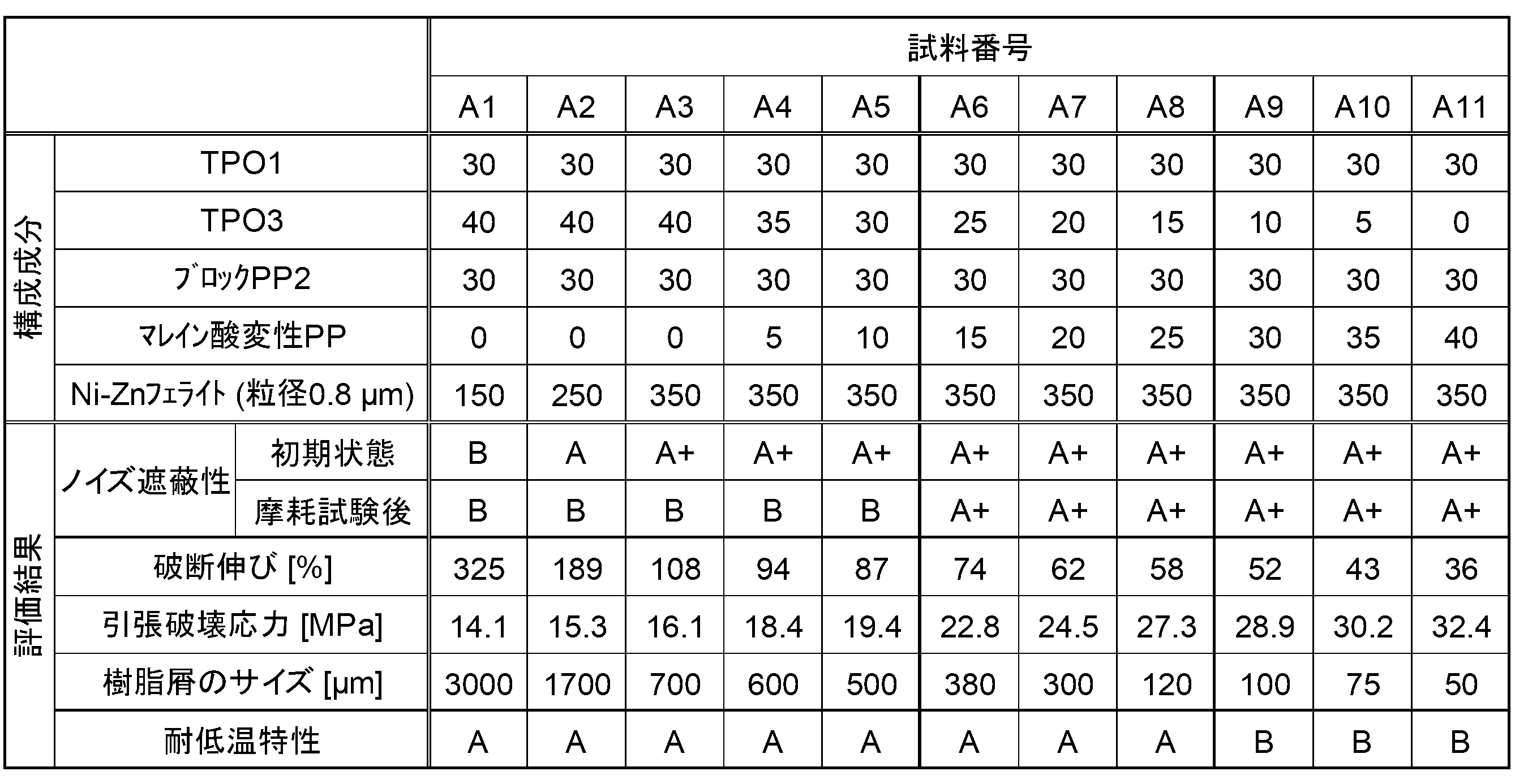
- samples A1 to A11 the compounding ratio of each component is changed.
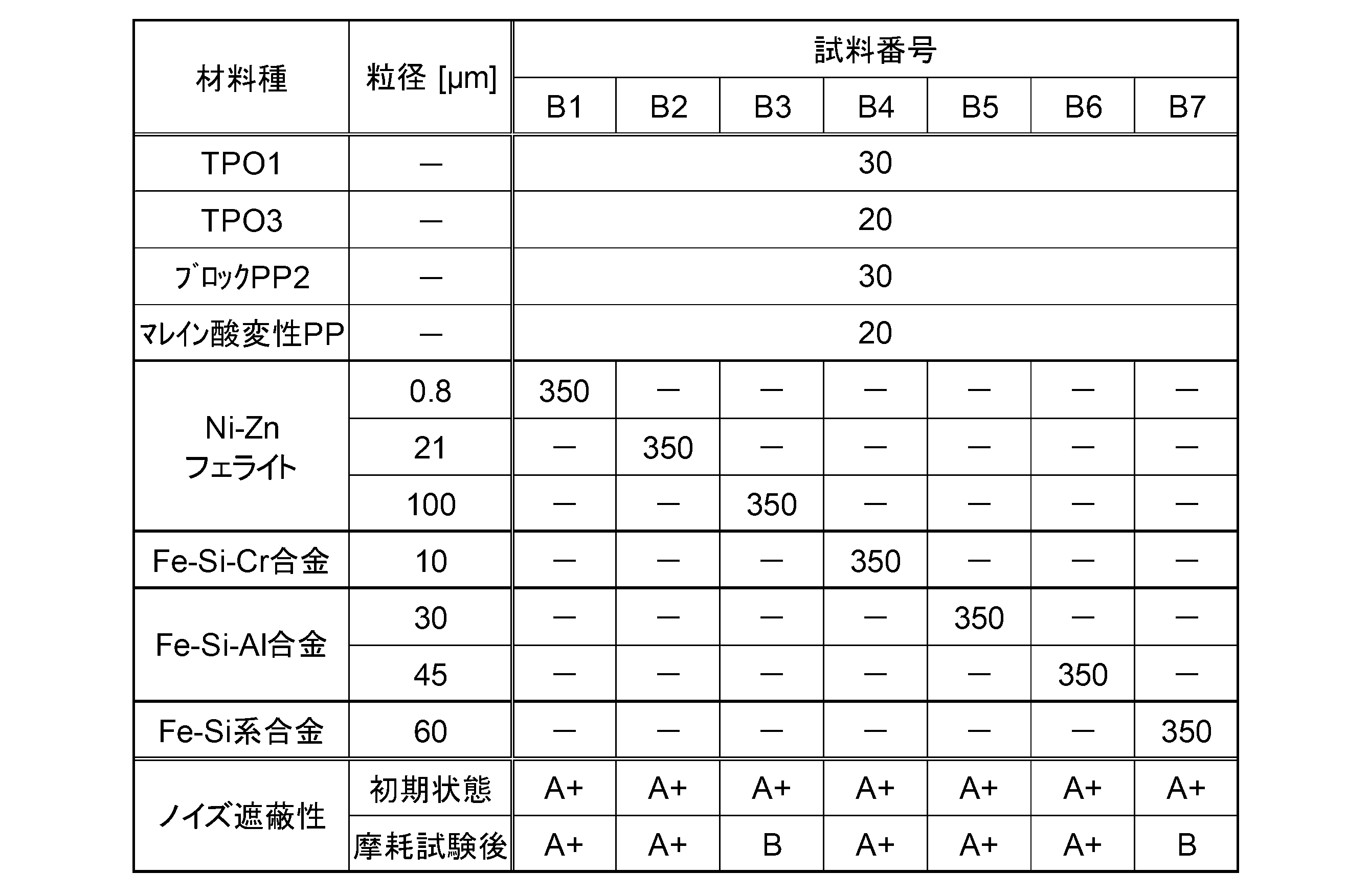
- samples B1 to B7 different magnetic materials are added.
- an outer sheath layer was formed on the outer periphery of the magnetic sheath layer by extrusion molding to complete a communication wire.
- the thickness of the outer sheath layer was 0.20 mm.
- a mixture of each component indicated as "outer sheath layer" in Table 1 below was used for each sample.
- the following components were used for the components constituting the insulating layer, the magnetic sheath layer, and the outer sheath layer.
- those used in the magnetic sheath layer are also shown together with the elongation at break and the tensile stress at break.
- TPO1 TPO “Adflex Q200F” manufactured by Lyondell Basel, elongation at break: 350%, tensile stress at break: 11 MPa
- TPO2 Exxon-Mobil TPO “Santoprene 203-40”
- TPO3 TPO “Tafmer PN-20300” manufactured by Mitsui Chemicals, breaking elongation: 1080%, tensile breaking stress: 21 MPa
- Block PP1 Block PP “Novatec EC9GD” manufactured by Japan Polypropylene Corporation
- Block PP2 Block PP “Novatec BC06C” manufactured by Japan Polypro Co., Ltd., elongation at break: 10%, tensile stress at break: 40 MPa ⁇
- Homo PP "Novatec EA9FTD” manufactured by Japan Polypro ⁇ Acid-modified SEBS: Asahi Kasei “Tuftec M1913” ⁇ Maleic acid-mod
- Magnetic material ⁇ As the Ni—Zn ferrite, products with the following three grain sizes (average grain size) were used. In both cases, the particle shape is irregular including uneven spheres. All are manufactured by JFE Chemical. "KNI-109": particle size 0.8 mm "KNI-109GSM”: Particle size 21mm “KNI-109GS”: Particle size 100mm ⁇ Fe-Si-Cr alloy: "AKT-7” manufactured by Mitsubishi Steel Corporation (particle shape: spherical without unevenness, particle size 10 ⁇ m) ⁇ As the Fe—Si—Al alloy, products with the following two grain sizes were used. All of them have a flat particle shape. Both are manufactured by Sanyo Special Steel Co., Ltd.
- High magnetic permeability fine powder type Particle size 30 ⁇ m
- High magnetic permeability type B particle size 45 ⁇ m
- Fe-Si alloy Sanyo Special Steel
- High magnetic permeability standard type (particle shape: flat shape, particle size 60 ⁇ m)
- Table 1 shows the component compositions of the materials used to fabricate the insulating layer and the outer sheath layer of all the samples in units of parts by mass.
- the noise shielding property was evaluated as "A+", which is particularly high.
- a case where the noise radiation amount was 16 dB ( ⁇ V/m) or more and less than 22 dB ( ⁇ V/m) was evaluated as high noise shielding "A”.
- a case where the noise radiation amount was 22 dB ( ⁇ V/m) or more was evaluated as "B” for low noise shielding.
- the evaluation was performed on the initial state of the manufactured communication wire and the state after the abrasion test. In the wear test, an iron wire with an outer diameter of 0.45 mm was pressed against the side circumference of the communication wire with a load of 7 N, and the wire was reciprocated 100 times.
- Table 2 shows the component composition (unit: parts by weight) of the magnetic sheath layer for each of samples A1 to A11 in which the compounding ratio of each component of the magnetic sheath layer was varied, and the results of each evaluation are shown in the lower row.
- Table 3 for each of Samples B1 to B7 in which the magnetic material added to the magnetic sheath layer was changed, the component composition (unit: parts by mass) of the magnetic sheath layer is shown in the upper row, and the noise shielding performance evaluation results are shown in the lower row. shown in Tables 2 and 3, the blending amount of each component is indicated assuming that the total of the organic polymer components is 100 parts by mass. Sample A7 and sample B1 are the same.
- the samples A1 and A2 in which the content of the magnetic material is less than 300 parts by mass, have lower noise shielding properties than the initial state before the abrasion test (B).
- samples A3 to A11 in which the content of the magnetic material was 300 parts by mass or more, exhibited high noise shielding properties in the initial state (A+). From this result, in order to obtain a sufficiently high noise shielding property in a communication wire, it is necessary to add 300 parts by mass or more of the magnetic material to 100 parts by mass of the organic polymer component in the magnetic sheath layer. I understand.
- samples A3 to A11 that had high noise shielding properties in the initial state samples A3 to A5 that did not contain maleic acid-modified PP or contained less than 15 parts by mass of maleic acid-modified PP had , the evaluation result of the noise shielding property is worse (B).
- samples A6 to A11 containing 15 parts by mass or more of maleic acid-modified PP maintained high noise shielding performance even after the abrasion test (A+). Furthermore, looking at the size of the resin waste generated in the wear test, the resin waste becomes finer as the maleic acid-modified PP content increases from sample A3 to sample A11.
- samples using any magnetic material have high noise shielding properties in the initial state before the wear test (A+).
- samples B3 and B7 in which the particle size of the magnetic material is larger than 50 ⁇ m, the noise shielding performance is low after the wear test (B), whereas sample B1, in which the particle size of the magnetic material is 50 ⁇ m or less, is low.
- B2, and B4 to B6 all maintained high noise shielding properties (A+) even after the wear test. From this, it can be seen that by setting the particle size of the magnetic material to 50 ⁇ m or less, the wear resistance of the magnetic sheath layer is enhanced, and high noise shielding properties are maintained even after wear.
- the magnetic materials used for samples B1 to B7 have different chemical compositions and different shapes such as irregular, spherical, and flat shapes. The results show that high noise shielding properties are maintained after passing through a
- the content of the acid-modified polymer in the magnetic sheath layer is 15 parts by mass or more and 25 parts by mass or less, high wear resistance and high low temperature resistance can be obtained. Furthermore, in samples A6 to A8, the breaking elongation of the magnetic sheath layer is 55% or more, and the tensile breaking stress is 28 MPa or less, and these physical property values are due to the suppression of the content of the acid-modified polymer. It can be said that this is an index corresponding to the improvement of low temperature resistance.
Landscapes
- Physics & Mathematics (AREA)
- Spectroscopy & Molecular Physics (AREA)
- Engineering & Computer Science (AREA)
- Microelectronics & Electronic Packaging (AREA)
- Insulated Conductors (AREA)
- Communication Cables (AREA)
- Soft Magnetic Materials (AREA)
Abstract
Description
最初に、本開示の実施態様を説明する。
本開示にかかる通信用電線は、導体と、前記導体の外周を被覆する絶縁層と、前記絶縁層の外側を被覆する磁性シース層と、を有し、前記磁性シース層は、有機ポリマーと、磁性材料と、を含有しており、前記磁性シース層は、前記有機ポリマー全体を100質量部として、15質量部以上の酸変性ポリマーを含んでおり、前記磁性材料は、平均粒径50μm以下の粒子として構成され、前記有機ポリマー全体を100質量部として、300質量部以上が前記磁性シース層に含有される。
以下、図面を用いて、本開示の一実施形態にかかる通信用電線について、詳細に説明する。以下、各種特性については、特記しない限り、常温、大気中で測定される値とする。
図1に、本開示の一実施形態にかかる通信用電線1について、軸線方向に垂直に切断した断面図を示す。通信用電線1は、同軸電線として構成されている。具体的には、通信用電線1は、導体2と、導体2の外周を被覆する絶縁層3とを有するコア線4を備えている。そして、コア線4の外周には、金属シールド層7として、金属箔5と、金属素線を編んだ編組体として構成された編組層6とが設けられている。金属箔5が、コア線4の外周を被覆し、さらに金属箔5の外周を被覆して、編組層6が設けられている。金属シールド層7の外周には、磁性材料を含有する磁性シース層8が設けられている。また、さらに磁性シース層8の外周に、磁性材料を含有しないアウターシース層9が設けられている。
コア線4は、通信用電線1において、電気信号の伝送を担う信号線であり、導体2と、導体2の外周を被覆する絶縁層3とを有している。導体2および絶縁層3を構成する材料は、特に限定されるものではない。
金属シールド層7は、コア線4と磁性シース層8との間に設けられており、金属箔5と編組層6とが積層された2層構造を有している。
磁性シース層8は、コア線4の外周を被覆するものである。本実施形態においては、磁性シース層8は、金属シールド層7を介して、コア線4の外周を被覆している。
1GHz以上等の高周波領域で、高いノイズ遮蔽性を示す軟磁性材料として、鉄(純鉄または少量の炭素を含む鉄)、Fe-Si系合金(ケイ素鋼)、Fe-Si-Al合金(センダスト)、Fe-Cr-Al-Si合金、Fe-Si-Cr合金等の磁性ステンレス鋼、Fe-Ni系合金(パーマロイ)、フェライト等を例示することができる。これらの材料の中で、ノイズ遮蔽性と低価格性に優れることから、フェライトを用いることが特に好ましい。フェライトとしては、Ni-Zn系のものを、特に好適に用いることができる。磁性材料は、1種のみを用いても、混合等により、2種以上を合わせて用いてもよい。
磁性シース層8を構成する材料は、有機ポリマーを含んでいる。その有機ポリマーには、少なくとも、酸変性ポリマーが含まれる。そして、酸変性ポリマーの含有量が、有機ポリマー成分全体を100質量部として、15質量部以上となっている。
以上のように、磁性シース層8は、有機ポリマー成分として、酸変性ポリマーを含有し、その酸変性ポリマーの含有量が、有機ポリマー成分100質量部のうち、15質量部以上となっていることにより、300質量部以上もの磁性材料を含有していても、高い破断強度を有するものとなる。磁性シース層8が高い破断強度を有することで、磁性シース層8が外部の部材との間で摩擦を受けても、磁性シース層8の表面が摩耗によって削り取られにくくなる。また、摩耗が起こることがあっても、その摩耗によって発生する樹脂屑が、微細なものとなりやすい。樹脂屑の微細化は、磁性シース層8を構成する磁性材料の平均粒径が50μm以下に抑えられていることによっても促進される。
アウターシース層9は、磁性シース層8の外周を被覆して設けられる層であり、通信用電線1全体としての外周に露出している。アウターシース層9は、不可避的不純物を除いて、磁性材料を含有していない。
銅合金の撚線として構成された導体の外周に、押出し成形によって絶縁層を形成して、コア線とした。絶縁層の構成材料としては、下の表1に、「絶縁層」として表示した各成分を混合したものを用いた。導体断面積は0.18mm2、絶縁層の厚さは0.54mmとした。
(有機ポリマー)
・TPO1:ライオンデル・バセル社製 TPO 「Adflex Q200F」、破断伸び:350%、引張破壊応力:11MPa
・TPO2:エクソン・モービル社製 TPO 「サントプレーン 203-40」
・TPO3:三井化学社製 TPO 「タフマー PN-20300」、破断伸び:1080%、引張破壊応力:21MPa
・ブロックPP1:日本ポリプロ社製 ブロックPP 「ノバテック EC9GD」
・ブロックPP2:日本ポリプロ社製 ブロックPP 「ノバテック BC06C」、破断伸び:10%、引張破壊応力:40MPa
・ホモPP:日本ポリプロ社製 「ノバテック EA9FTD」
・酸変性SEBS:旭化成社製 「タフテック M1913」
・マレイン酸変性PP:三井化学社製「アドマー QE820」、破断伸び:82%、引張破壊応力:22MPa
・Ni-Znフェライトとして、以下の3種の粒径(平均粒径)の製品を用いた。いずれも、粒子形状は、凹凸球形を含む不定形である。いずれも、JFEケミカル社製である。
「KNI-109」:粒径0.8mm
「KNI-109GSM」:粒径21mm
「KNI-109GS」:粒径100mm
・Fe-Si-Cr合金:三菱製鋼社製「AKT-7」(粒子形状:凹凸のない球形、粒径10μm)
・Fe-Si-Al合金として、以下の2種の粒径の製品を用いた。いずれも、粒子形状は、扁平形状である。いずれも、山陽特殊製鋼社製である。
「高透磁率微粉タイプ」:粒径30μm
「高透磁率 タイプB」:粒径45μm
・Fe-Si系合金:山陽特殊製鋼社製「高透磁率 標準タイプ」(粒子形状:扁平形状、粒径60μm)
・銅害防止剤:ADEKA社製 「CDA-1」
・ヒンダードフェノール系酸化防止剤:BASF社製 「Irganox 1010FF」
・硫黄系酸化防止剤:川口化学社製 「アンテージMB」(2-メルカプトベンゾイミダゾール)
・酸化亜鉛:ハクスイテック社製 「亜鉛華2種」
・難燃剤:協和化学工業株式会社製 「キスマ5」(水酸化マグネシウム)

(1)ノイズ遮蔽性
試料A1~A11および試料B1~B7にかかる通信用電線に対して、ノイズ遮蔽性を評価した。評価としては、CISPR25(国際無線障害特別委員会による「車載受信機保護のための妨害波の推奨限度値および測定法」の規格)に準拠した放射エミッション評価を行った。具体的には、電波暗室内にて、1500mmに切り出した通信用電線の中央部から側方に1.0m離した位置に、ホーンアンテナを設置した。そして、通信用電線に、1.6GHzの周波数の電気信号を入力し、この際のノイズ放射量を、ホーンアンテナにより計測した。ノイズ放射量が16dB(μV/m)未満の場合を、ノイズ遮蔽性が特に高い「A+」と評価した。ノイズ放射量が16dB(μV/m)以上22dB(μV/m)未満の場合を、ノイズ遮蔽性が高い「A」と評価した。ノイズ放射量が22dB(μV/m)以上の場合を、ノイズ遮蔽性が低い「B」と評価した。評価は、製造した通信用電線の初期状態と、摩耗試験を行った後の状態に対して行った。摩耗試験としては、通信用電線の側周部に、外径0.45mmの鉄線を荷重7Nで押し当てた状態で、100回往復運動させた。
JIS K 7161に準拠した引張試験により、試料A1~A11の磁性シース層の破断伸びおよび引張破壊応力を計測した。計測対象の試験片としては、上記のように通信用電線を形成する途中で、磁性シース層の形成まで完了した段階の電線に対し、内部のコア線と金属箔、編組層を引き抜いて除去したものを用いた。
試料A1~A11について、上記ノイズ遮蔽性試験の一環として行った摩耗試験において、磁性シース層から発生した樹脂屑を回収し、顕微鏡で観察した。樹脂屑のうち、長径(樹脂屑を横切る最長の直線)が最も長いものについて、その長径を樹脂屑のサイズとして記録した。
試料A1~A11について、耐低温特性を評価するために、低温巻き付け試験を行った。つまり、電線外径と等しいステンレス製の丸棒に各通信用電線を巻き付け、-40℃の低温に、4時間放置した。その後、目視にて磁性シース層の表面を観察し、亀裂が発生していない場合に、耐低温特性が高い「A」と評価した。亀裂が発生している場合には、耐低温特性が低い「B」と評価した。
表2に、磁性シース層の各成分の配合比を異ならせた試料A1~A11のそれぞれについて、磁性シース層の成分組成(単位:質量部)を上段に、各評価の結果を下段に示す。また、表3に、磁性シース層に添加する磁性材料を異ならせた試料B1~B7のそれぞれについて、磁性シース層の成分組成(単位:質量部)を上段に、ノイズ遮蔽性の評価結果を下段に示す。表2,3で、各成分の配合量は、有機ポリマー成分の合計を100質量部として表示している。試料A7と試料B1は同じものである。
2 導体
3 絶縁層
4 コア線
5 金属箔
6 編組層
7 金属シールド層
8 磁性シース層
9 アウターシース層
Claims (7)
- 導体と、
前記導体の外周を被覆する絶縁層と、
前記絶縁層の外側を被覆する磁性シース層と、を有し、
前記磁性シース層は、有機ポリマーと、磁性材料と、を含有しており、
前記磁性シース層は、前記有機ポリマー全体を100質量部として、15質量部以上の酸変性ポリマーを含んでおり、
前記磁性材料は、平均粒径50μm以下の粒子として構成され、前記有機ポリマー全体を100質量部として、300質量部以上が前記磁性シース層に含有される、通信用電線。 - 前記磁性シース層における前記酸変性ポリマーの含有量は、前記有機ポリマー全体を100質量部として、25質量部以下である、請求項1に記載の通信用電線。
- 前記磁性シース層は、前記有機ポリマーとして、前記酸変性ポリマーの他に、エラストマーを含んでいる、請求項1または請求項2に記載の通信用電線。
- 前記磁性シース層の引張破壊応力は、20MPa以上である、請求項1から請求項3のいずれか1項に記載の通信用電線。
- 前記磁性シース層の破断伸びは、80%以下である、請求項1から請求項4のいずれか1項に記載の通信用電線。
- 前記磁性シース層の破断伸びは、55%以上である、請求項1から請求項5のいずれか1項に記載の通信用電線。
- 前記通信用電線は、前記絶縁層の外周に金属シールド層を有する同軸電線として構成されており、
前記磁性シース層は、前記金属シールド層の外周に設けられている、請求項1から請求項6のいずれか1項に記載の通信用電線。
Priority Applications (2)
| Application Number | Priority Date | Filing Date | Title |
|---|---|---|---|
| CN202280008930.4A CN116806361A (zh) | 2021-01-20 | 2022-01-06 | 通信用电线 |
| US18/273,130 US20240105362A1 (en) | 2021-01-20 | 2022-01-06 | Communication electric wire |
Applications Claiming Priority (2)
| Application Number | Priority Date | Filing Date | Title |
|---|---|---|---|
| JP2021-007369 | 2021-01-20 | ||
| JP2021007369A JP7201013B2 (ja) | 2021-01-20 | 2021-01-20 | 通信用電線 |
Publications (1)
| Publication Number | Publication Date |
|---|---|
| WO2022158306A1 true WO2022158306A1 (ja) | 2022-07-28 |
Family
ID=82548755
Family Applications (1)
| Application Number | Title | Priority Date | Filing Date |
|---|---|---|---|
| PCT/JP2022/000253 Ceased WO2022158306A1 (ja) | 2021-01-20 | 2022-01-06 | 通信用電線 |
Country Status (4)
| Country | Link |
|---|---|
| US (1) | US20240105362A1 (ja) |
| JP (2) | JP7201013B2 (ja) |
| CN (1) | CN116806361A (ja) |
| WO (1) | WO2022158306A1 (ja) |
Cited By (1)
| Publication number | Priority date | Publication date | Assignee | Title |
|---|---|---|---|---|
| WO2020022393A1 (ja) | 2018-07-25 | 2020-01-30 | 味の素株式会社 | 磁性ペースト |
Families Citing this family (2)
| Publication number | Priority date | Publication date | Assignee | Title |
|---|---|---|---|---|
| US20240401175A1 (en) | 2021-10-27 | 2024-12-05 | Kabushiki Kaisha Kobe Seiko Sho (Kobe Steel, Ltd.) | Semi-hard magnetic steel component |
| JP2024130368A (ja) | 2023-03-14 | 2024-09-30 | 株式会社コベルコ科研 | 貼合せ基板の位置ずれ量測定装置および該方法ならびに半導体製造装置 |
Citations (3)
| Publication number | Priority date | Publication date | Assignee | Title |
|---|---|---|---|---|
| JP2016092380A (ja) * | 2014-11-11 | 2016-05-23 | 株式会社フジクラ | 電磁波遮蔽用樹脂組成物、及び、ケーブル |
| JP2020164695A (ja) * | 2019-03-29 | 2020-10-08 | 古河電気工業株式会社 | 樹脂組成物、及びそれを用いた配線材 |
| JP2020194726A (ja) * | 2019-05-29 | 2020-12-03 | 株式会社オートネットワーク技術研究所 | 通信用電線 |
Family Cites Families (3)
| Publication number | Priority date | Publication date | Assignee | Title |
|---|---|---|---|---|
| US4371742A (en) * | 1977-12-20 | 1983-02-01 | Graham Magnetics, Inc. | EMI-Suppression from transmission lines |
| US5206459A (en) * | 1991-08-21 | 1993-04-27 | Champlain Cable Corporation | Conductive polymeric shielding materials and articles fabricated therefrom |
| FR2907125B1 (fr) * | 2006-10-12 | 2012-09-21 | Arkema France | Composition resistant au choc a base de resine polyamide et d'un melange d'au moins un copolymere greffe a blocs polyamides et de polymere ethylenique basse densite |
-
2021
- 2021-01-20 JP JP2021007369A patent/JP7201013B2/ja active Active
-
2022
- 2022-01-06 WO PCT/JP2022/000253 patent/WO2022158306A1/ja not_active Ceased
- 2022-01-06 US US18/273,130 patent/US20240105362A1/en active Pending
- 2022-01-06 CN CN202280008930.4A patent/CN116806361A/zh active Pending
- 2022-12-21 JP JP2022204127A patent/JP2023040047A/ja not_active Withdrawn
Patent Citations (3)
| Publication number | Priority date | Publication date | Assignee | Title |
|---|---|---|---|---|
| JP2016092380A (ja) * | 2014-11-11 | 2016-05-23 | 株式会社フジクラ | 電磁波遮蔽用樹脂組成物、及び、ケーブル |
| JP2020164695A (ja) * | 2019-03-29 | 2020-10-08 | 古河電気工業株式会社 | 樹脂組成物、及びそれを用いた配線材 |
| JP2020194726A (ja) * | 2019-05-29 | 2020-12-03 | 株式会社オートネットワーク技術研究所 | 通信用電線 |
Cited By (2)
| Publication number | Priority date | Publication date | Assignee | Title |
|---|---|---|---|---|
| WO2020022393A1 (ja) | 2018-07-25 | 2020-01-30 | 味の素株式会社 | 磁性ペースト |
| EP3828901A4 (en) * | 2018-07-25 | 2022-05-04 | Ajinomoto Co., Inc. | MAGNETIC PASTE |
Also Published As
| Publication number | Publication date |
|---|---|
| US20240105362A1 (en) | 2024-03-28 |
| JP2022111740A (ja) | 2022-08-01 |
| JP2023040047A (ja) | 2023-03-22 |
| CN116806361A (zh) | 2023-09-26 |
| JP7201013B2 (ja) | 2023-01-10 |
Similar Documents
| Publication | Publication Date | Title |
|---|---|---|
| JP2023040047A (ja) | 通信用電線 | |
| CN108701515A (zh) | 通信用电线 | |
| CN108780681B (zh) | 通信用屏蔽电线 | |
| JPH05205536A (ja) | 遮蔽材及び遮蔽電線・ケーブル製品 | |
| JP7234708B2 (ja) | 通信用シールド電線 | |
| JP5199602B2 (ja) | 絶縁電線およびワイヤーハーネス | |
| JP7388527B2 (ja) | 通信用電線 | |
| JP2016020463A (ja) | 導電性樹脂組成物及びシールドケーブル | |
| JP7259848B2 (ja) | 絶縁層用樹脂組成物、絶縁電線及びケーブル | |
| WO2019058437A1 (ja) | 通信用シールド電線 | |
| JP5416484B2 (ja) | 車載用アンテナ同軸ケーブル | |
| JP7211575B2 (ja) | 通信用電線 | |
| JP2009176475A (ja) | 絶縁電線 | |
| WO2022190851A1 (ja) | 通信用電線 | |
| JP2022108557A (ja) | 通信用電線 | |
| KR102207956B1 (ko) | 고차폐성 및 고절연성을 갖는 오디오케이블 제작 방법 및 이에 의해 제작된 오디오케이블 | |
| WO2020241452A1 (ja) | 通信用電線 | |
| WO2023127622A1 (ja) | 通信用電線 | |
| WO2016088446A1 (ja) | 超電導ケーブル、及び超電導ケーブル用ケーブルコア | |
| CN117044416A (zh) | 屏蔽箔以及通信用电线 | |
| WO2023120554A1 (ja) | シールド材および通信用電線 | |
| JP2019014911A (ja) | 導電性樹脂組成物及びシールドケーブル |
Legal Events
| Date | Code | Title | Description |
|---|---|---|---|
| 121 | Ep: the epo has been informed by wipo that ep was designated in this application |
Ref document number: 22742430 Country of ref document: EP Kind code of ref document: A1 |
|
| WWE | Wipo information: entry into national phase |
Ref document number: 202280008930.4 Country of ref document: CN |
|
| WWE | Wipo information: entry into national phase |
Ref document number: 18273130 Country of ref document: US |
|
| NENP | Non-entry into the national phase |
Ref country code: DE |
|
| 122 | Ep: pct application non-entry in european phase |
Ref document number: 22742430 Country of ref document: EP Kind code of ref document: A1 |