WO2022158200A1 - 車両用操舵制御装置、ステアバイワイヤシステム、及びステアバイワイヤシステムの制御方法 - Google Patents
車両用操舵制御装置、ステアバイワイヤシステム、及びステアバイワイヤシステムの制御方法 Download PDFInfo
- Publication number
- WO2022158200A1 WO2022158200A1 PCT/JP2021/046739 JP2021046739W WO2022158200A1 WO 2022158200 A1 WO2022158200 A1 WO 2022158200A1 JP 2021046739 W JP2021046739 W JP 2021046739W WO 2022158200 A1 WO2022158200 A1 WO 2022158200A1
- Authority
- WO
- WIPO (PCT)
- Prior art keywords
- steering
- motor
- control device
- rotation angle
- vehicle
- Prior art date
Links
- 238000000034 method Methods 0.000 title claims abstract description 45
- 230000005856 abnormality Effects 0.000 claims abstract description 27
- 230000033001 locomotion Effects 0.000 claims description 6
- 238000013459 approach Methods 0.000 claims description 4
- 238000001514 detection method Methods 0.000 abstract description 34
- 238000010586 diagram Methods 0.000 description 18
- 238000004804 winding Methods 0.000 description 14
- 230000008569 process Effects 0.000 description 10
- 238000003745 diagnosis Methods 0.000 description 7
- 230000006870 function Effects 0.000 description 7
- 230000007246 mechanism Effects 0.000 description 7
- 238000004891 communication Methods 0.000 description 6
- 230000002159 abnormal effect Effects 0.000 description 5
- 230000004044 response Effects 0.000 description 3
- 230000005540 biological transmission Effects 0.000 description 2
- 238000012545 processing Methods 0.000 description 2
- 239000003638 chemical reducing agent Substances 0.000 description 1
- 230000007423 decrease Effects 0.000 description 1
- 238000012986 modification Methods 0.000 description 1
- 230000004048 modification Effects 0.000 description 1
- 230000000737 periodic effect Effects 0.000 description 1
- 238000005070 sampling Methods 0.000 description 1
Images


Classifications
-
- B—PERFORMING OPERATIONS; TRANSPORTING
- B62—LAND VEHICLES FOR TRAVELLING OTHERWISE THAN ON RAILS
- B62D—MOTOR VEHICLES; TRAILERS
- B62D5/00—Power-assisted or power-driven steering
- B62D5/04—Power-assisted or power-driven steering electrical, e.g. using an electric servo-motor connected to, or forming part of, the steering gear
- B62D5/0457—Power-assisted or power-driven steering electrical, e.g. using an electric servo-motor connected to, or forming part of, the steering gear characterised by control features of the drive means as such
- B62D5/0481—Power-assisted or power-driven steering electrical, e.g. using an electric servo-motor connected to, or forming part of, the steering gear characterised by control features of the drive means as such monitoring the steering system, e.g. failures
- B62D5/049—Power-assisted or power-driven steering electrical, e.g. using an electric servo-motor connected to, or forming part of, the steering gear characterised by control features of the drive means as such monitoring the steering system, e.g. failures detecting sensor failures
-
- B—PERFORMING OPERATIONS; TRANSPORTING
- B62—LAND VEHICLES FOR TRAVELLING OTHERWISE THAN ON RAILS
- B62D—MOTOR VEHICLES; TRAILERS
- B62D15/00—Steering not otherwise provided for
- B62D15/02—Steering position indicators ; Steering position determination; Steering aids
- B62D15/021—Determination of steering angle
- B62D15/0215—Determination of steering angle by measuring on the steering column
-
- B—PERFORMING OPERATIONS; TRANSPORTING
- B62—LAND VEHICLES FOR TRAVELLING OTHERWISE THAN ON RAILS
- B62D—MOTOR VEHICLES; TRAILERS
- B62D15/00—Steering not otherwise provided for
- B62D15/02—Steering position indicators ; Steering position determination; Steering aids
- B62D15/021—Determination of steering angle
- B62D15/0225—Determination of steering angle by measuring on a steering gear element, e.g. on a rack bar
-
- B—PERFORMING OPERATIONS; TRANSPORTING
- B62—LAND VEHICLES FOR TRAVELLING OTHERWISE THAN ON RAILS
- B62D—MOTOR VEHICLES; TRAILERS
- B62D5/00—Power-assisted or power-driven steering
- B62D5/04—Power-assisted or power-driven steering electrical, e.g. using an electric servo-motor connected to, or forming part of, the steering gear
- B62D5/0421—Electric motor acting on or near steering gear
-
- B—PERFORMING OPERATIONS; TRANSPORTING
- B62—LAND VEHICLES FOR TRAVELLING OTHERWISE THAN ON RAILS
- B62D—MOTOR VEHICLES; TRAILERS
- B62D5/00—Power-assisted or power-driven steering
- B62D5/04—Power-assisted or power-driven steering electrical, e.g. using an electric servo-motor connected to, or forming part of, the steering gear
- B62D5/0457—Power-assisted or power-driven steering electrical, e.g. using an electric servo-motor connected to, or forming part of, the steering gear characterised by control features of the drive means as such
- B62D5/0481—Power-assisted or power-driven steering electrical, e.g. using an electric servo-motor connected to, or forming part of, the steering gear characterised by control features of the drive means as such monitoring the steering system, e.g. failures
- B62D5/0484—Power-assisted or power-driven steering electrical, e.g. using an electric servo-motor connected to, or forming part of, the steering gear characterised by control features of the drive means as such monitoring the steering system, e.g. failures for reaction to failures, e.g. limp home
-
- H—ELECTRICITY
- H02—GENERATION; CONVERSION OR DISTRIBUTION OF ELECTRIC POWER
- H02P—CONTROL OR REGULATION OF ELECTRIC MOTORS, ELECTRIC GENERATORS OR DYNAMO-ELECTRIC CONVERTERS; CONTROLLING TRANSFORMERS, REACTORS OR CHOKE COILS
- H02P29/00—Arrangements for regulating or controlling electric motors, appropriate for both AC and DC motors
- H02P29/02—Providing protection against overload without automatic interruption of supply
- H02P29/024—Detecting a fault condition, e.g. short circuit, locked rotor, open circuit or loss of load
- H02P29/028—Detecting a fault condition, e.g. short circuit, locked rotor, open circuit or loss of load the motor continuing operation despite the fault condition, e.g. eliminating, compensating for or remedying the fault
-
- B—PERFORMING OPERATIONS; TRANSPORTING
- B62—LAND VEHICLES FOR TRAVELLING OTHERWISE THAN ON RAILS
- B62D—MOTOR VEHICLES; TRAILERS
- B62D5/00—Power-assisted or power-driven steering
- B62D5/001—Mechanical components or aspects of steer-by-wire systems, not otherwise provided for in this maingroup
- B62D5/005—Mechanical components or aspects of steer-by-wire systems, not otherwise provided for in this maingroup means for generating torque on steering wheel or input member, e.g. feedback
- B62D5/006—Mechanical components or aspects of steer-by-wire systems, not otherwise provided for in this maingroup means for generating torque on steering wheel or input member, e.g. feedback power actuated
-
- B—PERFORMING OPERATIONS; TRANSPORTING
- B62—LAND VEHICLES FOR TRAVELLING OTHERWISE THAN ON RAILS
- B62D—MOTOR VEHICLES; TRAILERS
- B62D5/00—Power-assisted or power-driven steering
- B62D5/04—Power-assisted or power-driven steering electrical, e.g. using an electric servo-motor connected to, or forming part of, the steering gear
- B62D5/0457—Power-assisted or power-driven steering electrical, e.g. using an electric servo-motor connected to, or forming part of, the steering gear characterised by control features of the drive means as such
- B62D5/046—Controlling the motor
-
- B—PERFORMING OPERATIONS; TRANSPORTING
- B62—LAND VEHICLES FOR TRAVELLING OTHERWISE THAN ON RAILS
- B62D—MOTOR VEHICLES; TRAILERS
- B62D6/00—Arrangements for automatically controlling steering depending on driving conditions sensed and responded to, e.g. control circuits
- B62D6/008—Control of feed-back to the steering input member, e.g. simulating road feel in steer-by-wire applications
Definitions
- the present invention relates to a vehicle steering control device, a steer-by-wire system, and a control method for the steer-by-wire system.
- the steer-by-wire system disclosed in Patent Literature 1 detects each detected value of a first motor rotation angle sensor and a second motor rotation angle sensor corresponding to two systems of an electric motor for steering, and detects a steering amount sensor. By comparing the values, it is determined which detected value is incorrect.
- the rotation angle of the motor shaft (in other words, the rotor Closed-loop control is performed by detecting the rotational position of the coil with a sensor and switching the current to the coil. Therefore, if the sensor that detects the rotation angle of the motor shaft fails, the closed loop control becomes impossible, and there is a possibility that the control of the steering angle according to the steering angle of the steering wheel cannot be continued.
- a sensor for detecting the rotation angle of the motor shaft is provided in triplicate, the failed sensor can be identified and the closed loop control can be continued using the normal sensor. The cost of the system will increase.
- the present invention has been made in view of the conventional circumstances, and its object is to prevent an increase in system cost and to continue controlling the steering angle even if the rotation angle sensor of the steering motor fails. , a steering control device for a vehicle, a steer-by-wire system, and a control method for the steer-by-wire system.
- the vehicle steering control device detects, when an abnormality is detected in the rotation angle sensor of the steering motor, the rotation angle of the motor shaft and the steering wheel before the abnormality is detected.
- the steering motor is open-loop controlled based on the information of the reaction force generator that applies the reaction torque to the .
- FIG. 1 is a schematic configuration diagram of a steer-by-wire system; FIG. It is a figure which shows the hardware of 1ECU which controls a steering device. It is a figure which shows the hardware of 2ECU which controls a reaction force generator. It is a block diagram which shows the control function of 2ECU. It is a block diagram which shows the control function of 1ECU. It is a flowchart which shows the control procedure of 2ECU. It is a flowchart which shows the control procedure of 1ECU. It is a flowchart which shows the control procedure of 1ECU. It is a figure which shows the energization pattern in a square wave drive system. 4 is a diagram showing the correlation between the steering angular velocity and the reference command effective current Iref; FIG.
- FIG. 1 is a configuration diagram showing one aspect of a steer-by-wire system 1000 provided in a vehicle 1 such as an automobile.
- the steer-by-wire system 1000 is a steering system that controls the steering angles of the steered wheels 2L and 2R, which are the front wheels of the vehicle 1, according to the steering angle of the steering wheel 500.
- the steering device 2000 is a device that can steer the steered wheels 2L and 2R by the operation of the steering motor 100
- the reaction force generating device 3000 is a device that can apply reaction torque to the steering wheel 500 by the operation of the reaction motor 600.
- the steering device 2000 and the reaction force generating device 3000 are mechanically separated.
- the steering device 2000 includes a steering motor 100 that generates a steering force applied to the steered wheels 2L and 2R, a first ECU (Electronic Control Unit) 200 that drives and controls the steering motor 100, a steering mechanism 300, and steering. and a turning angle sensor 400 for detecting the position of the mechanism 300 as information on the turning angles of the steered wheels 2L and 2R.
- the steering mechanism 300 is a mechanism that converts the rotational motion of the output shaft of the steering motor 100 into the linear motion of the steering rod 310, and uses a rack and pinion in this embodiment.
- steering rod 310 is provided with rack 311 that meshes with pinion 331 provided on pinion shaft 330 .
- the steering angle sensor 400 is configured by a pinion angle sensor that detects the angle of the pinion 331 or a stroke sensor that detects the amount of movement of the rack 311 .
- the steering motor 100 is a brushless motor and has a steering motor rotation angle sensor 101 capable of detecting the rotation angle (rotor position) of the motor shaft.
- the steering motor rotation angle sensor 101 is, for example, a Hall sensor.
- the first ECU 200 drives and controls the steering motor 100 by performing closed loop control for switching the current to the coil of the steering motor 100 based on the rotation angle detected by the steering motor rotation angle sensor 101 .
- the steering mechanism 300 may be a mechanism using, for example, a ball screw instead of the rack and pinion.
- a reaction force generating device 3000 (in other words, a steering input device) includes a steering wheel 500 operated by the driver of the vehicle 1 , a steering shaft 510 that rotates as the steering wheel 500 rotates, and a reaction force that is applied to the steering wheel 500 . It has a reaction force motor 600 that generates force torque, a second ECU 700 that drives and controls the reaction force motor 600, and a steering angle sensor 800 that detects the steering angle of the steering wheel 500.
- the reaction motor 600 is a brushless motor and has a reaction motor rotation angle sensor 601 capable of detecting the rotation angle (rotor position) of the motor shaft. Then, the second ECU 700 drives and controls the reaction motor 600 by performing closed-loop control to switch the current to the coil of the reaction motor 600 based on the rotation angle detected by the reaction motor rotation angle sensor 601 .
- the first ECU 200 and the second ECU 700 each have a microcomputer.
- the microcomputer of the first ECU 200 and the microcomputer of the second ECU 700 communicate with each other via a dedicated communication line, and the first ECU 200 and the second ECU 700 are connected to an in-vehicle communication line such as a Controller Area Network (CAN).
- CAN Controller Area Network
- the second ECU 700 calculates a steering angle command value (in other words, a target value of the steering angle) based on the steering angle of the steering wheel 500 detected by the steering angle sensor 800, and the calculated steering angle command value information to the first ECU 200 .
- the first ECU 200 provides information on the steering angle command value acquired from the second ECU 700 and information on the steering angles of the steered wheels 2L and 2R detected by the steering angle sensor 400 (in other words, information on the actual steering angle ) to feedback-control the energization of the steering motor 100 so that the actual steering angle approaches the steering angle command value.
- the second ECU 700 of the reaction force generator 3000 controls the energization of the reaction force motor 600 based on the target reaction torque information generated based on the estimation result of the external force applied to the steering mechanism 300, etc.
- a target reaction torque is generated.
- the first ECU 200 and the second ECU 700 constitute a control device 1100 that controls the turning angle and the steering reaction force in the steer-by-wire system 1000 .
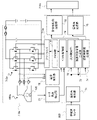
- FIG. 2 is a diagram showing the hardware configuration of the first ECU 200.
- a steered motor 100 that generates a steered force in the steering device 2000 is a three-phase brushless motor.
- the first ECU 200 has a first drive control system 210a that drives and controls the first winding set 100a and a second drive control system 210b that drives and controls the second winding set 100b.
- the drive control system is made redundant.
- the first drive control system 210a includes a first power supply circuit 211a, a first inverter 212a, a first pre-driver 213a (first drive circuit), a first MCU (Micro Control Unit) 214a as an arithmetic processing unit, and a first CAN transceiver 215a.
- the second drive control system 210b has a second power supply circuit 211b, a second inverter 212b, a second pre-driver 213b (first drive circuit), a second MCU 214b as an arithmetic processing unit, and a second CAN transceiver 215b.
- the first power supply circuit 211a is connected to the first battery 51a.
- the first power supply circuit 211a converts the input power supply voltage from the first battery 51a into a plurality of internal power supply voltages, and the plurality of internal power supply voltages are supplied to the first predriver 213a in the first drive control system 210a, the first 1MCU 214a is supplied to the first CAN transceiver 215a.
- the second power supply circuit 211b is connected to the second battery 51b.
- the second power supply circuit 211b converts the input power supply voltage from the second battery 51b into a plurality of internal power supply voltages, and the plurality of internal power supply voltages are supplied to the second predriver 213b in the second drive control system 210b, the second 2 MCU 214b and the second CAN transceiver 215b.
- the first MCU 214a and the second MCU 214b mutually transmit and receive information via the communication line 220, and, for example, transmit various kinds of abnormality information in their own system and information about inverter control in their own system to other systems.
- the first CAN transceiver 215a and the second CAN transceiver 215b are connected to a vehicle CAN bus 52, which is a communication line in a CAN (Controller Area Network) communication system.
- the first ECU 200 communicates with other electronic control devices including the second ECU 700 via the vehicle CAN bus 52
- the second ECU 700 communicates with other electronic control devices including the first ECU 200 via the vehicle CAN bus 52.
- the first MCU 214a and the second MCU 214b each acquire a signal relating to the steering angle output by the steering angle sensor 400, and also acquire information on the steering angle of the steering wheel 500 from the second ECU 700 via the vehicle CAN bus 52. , the energization of the winding sets 100a and 100b is controlled based on this information. Then, the first MCU 214a and the second MCU 214b control the turning angles of the steered wheels 2L and 2R to a target value according to the steering angle of the steering wheel 500 by controlling the energization of the winding sets 100a and 100b.
- the steering motor rotation angle sensor 101 is a redundant sensor having a plurality of sensors, and is composed of a first rotation angle sensor 101a and a second rotation angle sensor 101b.
- the first MCU 214a and the second MCU 214b switch currents to the winding sets 100a and 100b based on signals from the steering motor rotation angle sensor 101 (first rotation angle sensor 101a, second rotation angle sensor 101b).
- Implement loop control Also, the first MCU 214a and the second MCU 214b compare the detection value of the first rotation angle sensor 101a and the detection value of the second rotation angle sensor 101b to diagnose whether the steering motor rotation angle sensor 101 is faulty.
- FIG. 3 is a diagram showing the hardware configuration of the second ECU 700. As shown in FIG. The drive control system of the reaction force motor 600 in the reaction force generating device 3000 is also made redundant in the same way as the drive control system of the steering motor 100 in the steering device 2000 .
- the reaction force motor 600 is a three-phase brushless motor similar to the steered motor 100, and has a winding set consisting of a U-phase coil, a V-phase coil, and a W-phase coil as a first winding set 600a and a second winding. There are two sets of sets 600b.
- the second ECU 700 has a first drive control system 710a that drives and controls the first winding set 600a, and a second drive control system 710b that drives and controls the second winding set 600b.
- the drive control system is made redundant.
- the first drive control system 710a has a first power supply circuit 711a, a first inverter 712a, a first pre-driver 713a (first drive circuit), a first MCU 714a, and a first CAN transceiver 715a.
- the second drive control system 710b has a second power supply circuit 711b, a second inverter 712b, a second pre-driver 713b (second drive circuit), a second MCU 714b, and a second CAN transceiver 715b.
- the first power supply circuit 711a is connected to the first battery 51a.
- the first power supply circuit 711a converts the input power supply voltage from the first battery 51a into a plurality of internal power supply voltages, and the plurality of internal power supply voltages are supplied to the first predriver 713a in the first drive control system 710a, the first 1MCU 714a, supplied to the first CAN transceiver 715a.
- the second power supply circuit 711b is connected to the second battery 51b.
- the second power supply circuit 711b converts the input power supply voltage from the second battery 51b into a plurality of internal power supply voltages, and the plurality of internal power supply voltages are supplied to the second predriver 713b in the second drive control system 710b, the second 2MCU 714b, 2nd CAN transceiver 715b.
- the first MCU 714a and the second MCU 714b mutually transmit and receive information via the communication line 720, and, for example, transmit various kinds of abnormality information in their own system and information about inverter control in their own system to other systems. Also, the first CAN transceiver 715 a and the second CAN transceiver 715 b are connected to the vehicle CAN bus 52 .
- Each of the first MCU 714a and the second MCU 714b acquires a signal related to the steering angle of the steering wheel 500 output by the steering angle sensor 800, calculates a turning angle command value based on the information related to the steering angle, and obtains information on the turning angle command value. is transmitted to the first ECU 200 of the steering device 2000 via the vehicle CAN bus 52 .
- the first MCU 714a and the second MCU 714b each acquire information about the target value of the steering reaction force from the steering device 2000 via the vehicle CAN bus 52, and control energization of the winding sets 600a and 600b based on the acquired information.
- the steering reaction force generated by the reaction force motor 600 is controlled.
- the reaction motor 600 includes a rotation angle sensor (not shown) that detects the rotation angle of the motor shaft of the reaction motor 600, and the first MCU 714a and the second MCU 714b detect the rotation angle of the reaction motor 600. Closed-loop control of the reaction motor 600 is performed by switching the current to each winding set 600a, 600b.
- FIG. 4 is a block diagram showing the control function of the first MCU 714a of the first drive control system 710a of the second ECU700. Since the second MCU 714b of the second drive control system 710b has the same control function as the first MCU 714a, illustration of the second drive control system 710b is omitted in FIG.
- Steering angle detection unit 71 acquires a signal output from steering angle sensor 800 and detects the steering angle of steering wheel 500 based on the acquired signal. Then, the steering angle detection unit 71 transmits information on the steering angle of the steering wheel 500 to the reaction force control unit 72, the steering angle command value generation unit 73, and the steering angle information generation unit 74, respectively. Reaction force control unit 72 calculates a target reaction force torque from information such as the steering angle of steering wheel 500 .
- the turning angle command value generation unit 73 calculates a turning angle command value based on the information on the steering angle of the steering wheel 500 and the set value of the steering gear ratio, and uses the information on the calculated turning angle command value as a command turning. It is transmitted to the angle information transmission section 75 .
- the command turning angle information transmitting unit 75 transmits information on the turning angle command value to the first MCU 214a of the first drive control system 210a of the first ECU200.
- the steering angle information generation unit 74 generates information on the steering angle (or steering angular velocity) of the steering wheel 500 to be transmitted to the first drive control system 210a of the first ECU200. Then, the steering angle information transmission unit 76 uses information of the steering angle (or steering angular velocity) of the steering wheel 500 generated by the steering angle information generation unit 74 as information of the reaction force generation device 3000 for the first drive control of the first ECU 200. It is transmitted to the first MCU 214a of system 210a.
- the motor angle detection unit 77 acquires a signal from a rotation angle sensor 120 that detects the rotation angle (rotation position of the rotor, magnetic pole position) of the motor shaft of the reaction motor 600, and detects the rotation of the motor shaft of the reaction motor 600. Detect corners. Further, the current detection unit 78 detects drive currents (phase currents) flowing through each phase (U phase, V phase, W phase) of the reaction motor 600 .
- the vector control unit 79 acquires information on the target reaction torque from the reaction force control unit 72, acquires information on the rotation angle of the motor shaft of the reaction motor 600 from the motor angle detection unit 77, and further acquires the current detection unit 78. , and the d-axis voltage command value Vd and the q-axis voltage command value Vq are calculated by a vector control method based on this information. Specifically, the vector control unit 79 converts the actual currents of the three phases into d-axis actual currents and q-axis actual currents, and converts the d-axis current command values and the q-axis current command values according to the target reaction torque. , the d-axis actual current and the q-axis actual current, the d-axis voltage command value Vd and the q-axis voltage command value Vq are obtained.
- the vector control unit 79 converts the d-axis voltage command value Vd and the q-axis voltage command value Vq into three-phase command voltages Vu, Vv, and Vw based on the rotation angle of the motor shaft of the reaction motor 600, Three-phase command voltages Vu, Vv, and Vw are output to PWM generator 80 .
- PWM generator 80 outputs control pulses for ON/OFF control of each switching element of inverter 712a to predriver 713a by PWM based on three-phase command voltages Vu, Vv, and Vw.
- FIG. 5 is a block diagram showing the control function of the first MCU 214a of the first drive control system 210a of the first ECU200. Since the second MCU 214b has the same control function as the first MCU 214a, illustration of the second drive control system 210b is omitted in FIG.
- the command turning angle information receiving unit 21 acquires information on the turning angle command value from the command turning angle information transmitting unit 75 of the first drive control system 710a of the second ECU700.
- the steering angle detection unit 22 acquires a signal output from the steering angle sensor 400 and detects the steering angles of the steered wheels 2L and 2R.
- the motor angle detection unit 23 includes a steering motor rotation angle sensor 101 (a first rotation angle sensor 101a and a second rotation angle sensor 101b) that detects the rotation angle of the motor shaft of the steering motor 100 (rotational position of the rotor, magnetic pole position). ) is obtained, and the rotation angle of the motor shaft of the steering motor 100 is detected. Further, the current detection unit 24 detects a current (phase current) flowing through each phase (U-phase, V-phase, W-phase) of the steering motor 100 respectively.
- a steering motor rotation angle sensor 101 a first rotation angle sensor 101a and a second rotation angle sensor 101b
- the feedback control unit 25 acquires information on the turning angle command value (target value) from the command turning angle information receiving unit 21, and obtains the turning angle (actual turning angle) of the steered wheels 2L and 2R from the turning angle detection unit 22. angle), and information on the rotation angle of the motor shaft of the steering motor 100 is acquired from the motor angle detection unit 23 . Then, the feedback control unit 25 calculates a target turning torque for bringing the actual turning angle closer to the turning angle command value (in other words, the turning angle target value).
- the vector control unit 26 acquires information on the target steering torque from the feedback control unit 25, acquires information on the rotation angle of the motor shaft of the steering motor 100 from the motor angle detection unit 23, and further acquires information on the rotation angle of the motor shaft of the steering motor 100 from the current detection unit 24. Phase current information is acquired, and a d-axis voltage command value Vd and a q-axis voltage command value Vq are calculated by a vector control method. Specifically, the vector control unit 26 provides a d-axis current command value and a q-axis current command value corresponding to the target steering torque, and a d-axis current and a q-axis current obtained by converting the three-phase real phase currents. A d-axis voltage command value Vd and a q-axis voltage command value Vq are obtained according to the deviation from .
- the vector control unit 26 converts the d-axis voltage command value Vd and the q-axis voltage command value Vq into three-phase command voltages Vu, Vv, and Vw based on information on the rotation angle of the motor shaft of the steered motor 100, It outputs three-phase command voltages Vu, Vv, and Vw.
- the PWM generator 28 outputs a control command for ON/OFF-controlling each switching element of the inverter 212a to the predriver 213a by PWM based on the three-phase command voltages Vu, Vv, and Vw.
- the drive signal switching unit 27 arranged in the preceding stage of the PWM generation unit 28 selects either the command voltage from the vector control unit 26 or the command voltage from the failure voltage waveform generation unit 29 to the steering motor. Selection is made according to the presence or absence of an abnormality in the rotation angle sensor 101 , and the selected command voltage is output to the PWM generator 28 .
- the voltage waveform generator 29 generates a voltage waveform by open loop control before the abnormality is detected. is generated based on the detected motor rotation angle and the information of the reaction force generator 3000 (specifically, the steering angle or the steering angular velocity).
- the drive signal switching unit 27 outputs the command voltage generated by the vector control unit 26 by closed loop control to the PWM generation unit 28, and the steering motor rotation angle sensor 101 If abnormal, the open-loop control command voltage generated by the fault voltage waveform generator 29 is output to the PWM generator 28 . In other words, the drive signal switching unit 27 switches between closed loop control and open loop control depending on whether the steering motor rotation angle sensor 101 is abnormal.
- the failure diagnosis unit 30 acquires information on the motor rotation angle detection value from the motor angle detection unit 23, that is, the rotation angle detection value of the first rotation angle sensor 101a and the rotation angle detection value of the second rotation angle sensor 101b. . Then, the failure diagnosis unit 30 compares the rotation angle detection value of the first rotation angle sensor 101a and the rotation angle detection value of the second rotation angle sensor 101b. 101 is normal, and if the two do not match, it is determined that the turning motor rotation angle sensor 101 is out of order, and the diagnostic result information is sent to the feedback control unit 25 and the voltage waveform generation unit 29 at failure. do.
- the steering angle information receiving section 32 acquires information on the steering angle (or steering angular velocity) of the steering wheel 500 from the steering angle information transmitting section 76 of the first MCU 714 a of the reaction force generating device 3000 . Then, the motor rotation speed setting unit 31 adjusts the steering motor speed based on the information of the steering angle (or the steering angular speed) of the steering wheel 500 acquired by the steering angle information receiving unit 32, in other words, based on the information of the reaction force generating device 3000. A rotation speed command value (target value) of 100 is set.
- the fault voltage waveform generation unit 29 receives the rotation speed command value set by the motor rotation speed setting unit 31 and the diagnosis result of the steering motor rotation angle sensor 101 in the failure diagnosis unit 30 (whether there is an abnormality in the steering motor rotation angle sensor 101). ), control information of the feedback control unit 25, and the like.
- the failure voltage waveform generator 29 When the steering motor rotation angle sensor 101 has an abnormality and the closed loop control cannot be executed, the failure voltage waveform generator 29 generates a voltage waveform for open loop control of the steering motor 100 and drives the steering motor 100. Output to the signal switching unit 27 .
- FIG. 6 is a flowchart showing a control process in the second ECU 700 of the reaction force generator 3000, that is, a control procedure of the reaction force motor 600. As shown in FIG. The control process shown in the flowchart of FIG. 6 is executed in parallel by the first MCU 714a of the first drive control system 710a and the second MCU 714b of the second drive control system 710b.
- the second 2ECU 700 is activated in step S751 in response to the ON operation of the ignition switch, which is the main switch for driving and stopping the vehicle 1 . Then, the second ECU 700 detects the steering angle of the steering wheel 500 from the output of the steering angle sensor 800 in step S752, detects the rotation angle of the motor shaft of the reaction motor 600 from the output of the rotation angle sensor 120 in step S753, Furthermore, in step S754, the motor current (specifically, each phase current) of the reaction motor 600 is detected.
- the second ECU 700 calculates the steering angular velocity of the steering wheel 500 in step S755, calculates the command value of the steering reaction force (reaction torque) in step S756, and further steering angle information of the steering wheel 500 in step S757 , the steering angle command values for the steered wheels 2L and 2R are calculated.
- the second ECU 700 transmits information on the steering angle command value to the first ECU 200 of the steering device 2000 in step S758, and transmits information on the steering angular velocity of the steering wheel 500 to the first ECU 200 of the steering device 2000 in step S759. do.
- the second ECU 700 may transmit information on the steering angle of the steering wheel 500 to the first ECU 200, and the first ECU 200 may calculate the steering angular velocity.
- the second 2ECU 700 calculates the voltage command value of each phase according to the command value of the steering reaction force and the rotation angle of the motor shaft of the reaction force motor 600 by vector control in step S760. Then, the second 2ECU700, in step S761, determines the duty ratio in the PWM control of the inverters 712a, 712b based on the voltage command value of each phase, in the next step S762, the inverters 712a, 712b switching element pulse signal to turn on and off to drive the reaction force motor 600 .
- the second 2ECU 700 determines whether the ignition switch is turned on or off in step S763. Then, if the ignition switch is on, the second 2ECU 700 returns to step S752 and repeats the control process of steps S752 to S762, and if the ignition switch is off, terminates the control process.
- FIG. 7 and 8 are flowcharts showing the control process in the first ECU 200 of the steering system 2000, that is, the control procedure of the steering motor 100.
- FIG. 7 and 8 are executed in parallel by the first MCU 214a of the first drive control system 210a and the second MCU 214b of the second drive control system 210b.
- the first ECU 200 is activated in step S251 in response to turning on the ignition switch. Then, the first ECU 200 acquires information on the steering angle command value from the second ECU 700 in step S252, and acquires information on the steering angular velocity (or steering angle) from the second ECU 700 in the next step S253.
- step S254 the first ECU 200 detects the rotation angle ⁇ mot of the motor shaft of the steering motor 100 based on the output of the steering motor rotation angle sensor 101, and in step S255, the motor current of the steering motor 100 (each phase current). Next, the first ECU 200 performs failure diagnosis of the steering motor rotation angle sensor 101 in step S256.
- the steering motor rotation angle sensor 101 is made redundant and is composed of a first rotation angle sensor 101a and a second rotation angle sensor 101b. Therefore, the first ECU 200 compares the detection result of the first rotation angle sensor 101a and the detection result of the second rotation angle sensor 101b as a failure diagnosis of the steering motor rotation angle sensor 101, and if they match, the rotation is performed. It is determined that the rudder motor rotation angle sensor 101 is normal.
- the method of diagnosing the steering motor rotation angle sensor 101 is not limited to comparing the outputs of the two sensors. 101 anomalies can be detected.
- the first ECU 200 determines the result of failure diagnosis of the steering motor rotation angle sensor 101 in the next step S257.
- the first ECU 200 proceeds to step S258 and thereafter, and switches current to the coil based on the motor rotation angle detected by the steering motor rotation angle sensor 101 by closed loop control. Normal control for driving the rudder motor 100 is executed.
- the first ECU 200 sets a target value (motor torque command value) of the turning torque (torque generated by the turning motor 100) based on, for example, the deviation between the turning angle command value information and the actual turning angle information. ) to perform feedback control of the turning angle.
- the first ECU 200 updates the normal motor angle ⁇ norm stored in the memory based on the latest detected value by the steering motor rotation angle sensor 101 in step S259. That is, the normal motor angle ⁇ norm is successively updated to a value that matches the value detected by the steering motor rotation angle sensor 101 when the steering motor rotation angle sensor 101 is normal.
- the normal motor angle ⁇ norm is the rotation angle detection value of the motor shaft of the steering motor 100 before the abnormality of the steering motor rotation angle sensor 101 is detected.
- the first ECU 200 updates the plurality of sensors constituting the steering motor rotation angle sensor 101, that is, the first rotation angle sensor 101a and the second rotation angle sensor 101b.
- the normal motor angle ⁇ norm can be updated based on the average value of the detection results.
- the first ECU 200 can accurately update the normal motor angle ⁇ norm even if there is a difference in sampling timing between the outputs of the two rotation angle sensors 101a and 101b. .
- the first ECU 200 calculates an electrical angle ⁇ mot_e from the motor rotation angle ⁇ mot (mechanical angle) in step S260. Then, the first ECU 200 proceeds from step S260 to step S272, and calculates the three-phase command voltages Vu, Vv, and Vw for generating the target value of turning torque (motor torque command value) by the vector control method.
- the first ECU 200 sets the d-axis and q-axis command currents according to the target value of the steering torque, and converts the three-phase current detection values to the d-axis and q-axis actual currents based on the electrical angle ⁇ mot_e.
- d-axis voltage command value Vd and q-axis voltage command value Vq are calculated based on the deviation between the d-axis command current, the q-axis command current and the d-axis actual current and the q-axis actual current, and furthermore, the d-axis voltage command
- the value Vd and the q-axis voltage command value Vq are converted into three-phase command voltages Vu, Vv, and Vw based on the electrical angle ⁇ mot_e. That is, the first ECU 200 changes the three-phase command voltages Vu, Vv, and Vw based on the current detection values of the three phases so that the target value of the turning torque for matching the turning angle with the command value is actually obtained. to execute motor current feedback control.
- step S273 the first ECU 200 determines the duty ratio for ON/OFF-controlling each switching element of the inverter 712a by PWM based on the three-phase command voltages Vu, Vv, and Vw. Then, in the next step S274, the first ECU 200 outputs a PWM signal for on/off controlling each switching element of the inverter 712a based on the electrical angle ⁇ mot_e and the duty ratio.
- the first ECU 200 uses a known rectangular wave driving method (in other words, a 120-degree conduction method or a 120-degree phase rectangular wave driving method) and a sine wave driving method (in other words, For example, a sinusoidal drive system with a phase of 120 degrees) can be adopted.
- a sine wave driving method in other words, a sinusoidal drive system with a phase of 120 degrees
- the motor is driven smoothly, so vibration from the steering device 2000 is suppressed, and the quietness of the vehicle 1 can be ensured.
- the rectangular wave driving method the maximum power supply voltage can be used, so that a large driving torque can be output and the controllability of the turning angle is improved.
- FIG. 9 shows the switching timing of each switching element of the inverter in the rectangular wave driving system.
- the first phase has the high side (upper arm) turned off and the low side (lower arm) turned on
- the second phase has the low side turned off.
- Each switching element is switched in an energization pattern in which the high side is on in the third phase and both the high side and the low side are off in the third phase.
- the high side or low side of any phase is turned on for a period of 120 degrees, both the high side and low side are turned off for a period of 60 degrees.
- the sinusoidal wave drive method is a drive method in which sinusoidal currents with a phase difference of 120° flow through each winding of three phases (U-phase, V-phase, and W-phase).
- the motor applied voltage can be maximized.
- the first ECU 200 determines whether the ignition switch is on or off in the next step S275. The control process of the steering motor 100 is terminated. On the other hand, when the first ECU 200 detects an abnormality in the turning motor rotation angle sensor 101 in step S257, the process proceeds to step S261 and subsequent steps.
- the first ECU 200 continues to control the steering motor 100 by switching to open-loop control in which power supply is controlled without using the detection output of the steering motor rotation angle sensor 101 after step S261. Therefore, the first ECU 200 can continue to control the steering angle even when the steering motor rotation angle sensor 101 fails.
- the first ECU 200 since the first ECU 200 switches from closed loop control to open loop control when the steering motor rotation angle sensor 101 fails, the sensors constituting the steering motor rotation angle sensor 101 should be multiplexed to three or more. The control of the steering angle can be continued without any need, and the cost increase of the steer-by-wire system can be suppressed.
- the first ECU 200 selectively uses self-limiting open loop control and non-limiting open loop control as the open loop control, as will be described later in detail.
- Self-restraint open loop control is an operation mode that detects the induced voltage generated in the non-energized coil due to the rotation of the permanent magnet, detects the position based on the detected induced voltage, and switches the energization.
- Multimodal open loop control is an open control method in which a periodic voltage is applied in a feedforward manner regardless of the magnetic pole position.
- the first ECU 200 controls the steering motor 100 by multi-regulation open loop control in a low speed range from zero (motor stopped state) to a predetermined speed, and controls the steering motor 100 in a high speed range in which the motor rotation speed is equal to or higher than the predetermined speed. Then, the steering motor 100 is controlled by self-regulating open loop control.
- step S261 the first ECU 200 determines whether the process proceeds to step S261 for the first time after detecting an abnormality in the steering motor rotation angle sensor 101, in other words, it is the first time after the abnormality in the steering motor rotation angle sensor 101 is detected. or not.
- the first ECU 200 proceeds to step S262, and the normal motor angle ⁇ norm, that is, the abnormality of the steering motor rotation angle sensor 101 is detected in the initial value of the failure motor angle ⁇ op.
- a rotation angle detection value before the rotation angle is set (in other words, the rotation angle detected last when the steering motor rotation angle sensor 101 is in a normal state) is set.
- the failure motor angle ⁇ op indicates the rotational position of the motor shaft of the steering motor 100 instead of the value detected by the steering motor rotation angle sensor 101 when the steering motor rotation angle sensor 101 becomes abnormal. This is information, and the first ECU 200 switches energization to the coil based on the failure-time motor angle ⁇ op in the multi-regulation open loop control.
- step S261 the first ECU 200 bypasses step S262 and proceeds to step S263.
- step S263 the first ECU 200 calculates a motor rotation speed ⁇ op (n) as a rotation speed command value in open loop control (specifically, open loop control with other control) based on information on the steering angular velocity of the steering wheel 500. do.
- the first ECU 200 performs multi-regulation open loop control so that the rotational speed of the steering motor 100 is proportional to the steering angular velocity.
- step S264 the first ECU 200 converts the motor rotation speed ⁇ op (n ) is updated.
- the first ECU 200 determines in step S265 whether or not the motor rotation speed ⁇ op (n-1) is equal to or higher than the set rotation speed ⁇ th.
- the set rotation speed ⁇ th is a rotation speed set based on the lower limit of the rotation speed range in which the magnetic pole position can be estimated sensorlessly based on the motor induced voltage. If there is, it indicates that a motor induced voltage is generated that is large enough to estimate the magnetic pole position (rotor rotational position) with sufficient accuracy.
- step S269. Proceed further to implement self-imposed open-loop control.
- the motor rotation speed ⁇ op (n ⁇ 1) is less than the set rotation speed ⁇ th and the rotation speed condition that enables sensorless estimation of the magnetic pole position based on the motor induced voltage is not satisfied, the first ECU 200 Proceeding to step S266 and subsequent steps, multi-regulation open loop control for switching the current to the coil is performed based on the information on the motor angle ⁇ op at failure.
- the first ECU 200 sets the motor rotation speed ⁇ op (n) based on the information on the steering angular velocity of the steering wheel 500, when the steering angular velocity is smaller than a predetermined steering angular velocity, the steering angle is controlled by the multi-regulation open loop control.
- the motor 100 is controlled, and when the steering angular velocity is equal to or higher than the predetermined steering angular velocity, the steering motor 100 is controlled by self-limiting open loop control.
- step S266 the first ECU 200 calculates the motor electrical angle ⁇ op_e from the failure motor angle ⁇ op. Calculate.
- step S267 the first ECU 200 sets the target command effective current Icmd of the steering motor 100 during multi-regulation open loop control to the steering angular velocity based on the motor rotational speed ⁇ op (n) , the vehicle speed of the vehicle 1, and the actual current Icmd. It is calculated based on the steering angle.
- FIG. 10 is a graph showing the correlation between the steering angular velocity and the reference command effective current Iref.
- the reference command effective current Iref is set to a larger current as the steering angular velocity is faster and the motor torque is requested higher.
- FIG. 11 is a graph showing the correlation between the vehicle speed and the vehicle speed coefficient Kspd. Since the lower the vehicle speed, the higher the steering load, the vehicle speed coefficient Kspd is set so that the lower the vehicle speed, the higher the target command effective current Icmd. set.
- FIG. 12 is a graph showing the correlation between the actual turning angle and the turning angle coefficient Kstr. Since the turning load increases as the actual turning angle increases, the turning angle coefficient Kstr The target command effective current Icmd is set to increase as the steering angle increases. By setting the target command effective current Icmd as described above, it is possible to control the steering motor 100 without losing synchronism while improving follow-up performance.
- the first ECU 200 can variably set the target command effective current Icmd based on at least one of the steering angular velocity, vehicle speed, and actual steering angle.
- step S268 the first ECU 200 calculates the command voltage value so that the actual current value approaches the target command effective current Icmd (command current value). Then, the first ECU 200 proceeds from step S268 to step S273, and calculates the duty ratio for turning on/off the switching elements of the inverters 212a and 212b based on the command voltage value. Furthermore, in step S274, the first ECU 200 synchronizes with the motor electrical angle ⁇ op_e and outputs a PWM signal (in other words, a gate signal) that turns on and off the switching elements of the inverters 212a and 212b according to the duty ratio.
- a PWM signal in other words, a gate signal
- the first ECU 200 terminates the feedback control when the absolute value of the difference between the steering angle command value and the actual steering angle becomes equal to or less than a predetermined value in the multi-regulation open loop control in steps S267 and S268.
- the current flowing through the steering motor 100 is reduced to a predetermined current value.
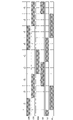
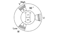
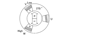
- 13 to 18 show the correlation between the energized phase and the rotor stability angle in the square wave drive system. For example, as shown in FIG. 13, if the current continues to flow from the U phase to the W phase, the rotor stabilizes at the 30° position, and conversely, as shown in FIG. , the rotor stabilizes at the 210° position.
- FIG. 19 is a graph showing the correlation between the magnitude of current and the magnitude of torque generated toward the stable angle of the rotor. For example, when a constant current is passed from the U phase to the W phase, if the rotor position deviates from the stable angle of 30°, a torque is generated toward the 30° position, and the rotor rotates at the stable angle of 30°. It rotates to the position of ° and stabilizes. Here, the torque toward the 30° position increases as the current applied to the coil increases.
- the first ECU 200 controls the steering motor 100 when the absolute value of the difference between the steering angle command value and the actual steering angle becomes equal to or less than a predetermined value in the other control open loop control in steps S267 and S268.
- the current to be applied is reduced to a predetermined current value that can hold the position of the rotor, and the current continues to flow through the same two phases.
- power consumption is suppressed when the turning angle command value and the actual turning angle substantially match and the turning angle does not need to be changed (in other words, when a constant turning angle is maintained). can.
- step S269 self-restraining open loop control after step S269 will be described. Note that the first ECU 200 switches energization to the coil using the estimated value of the motor rotation angle based on the motor induced voltage instead of the detection output of the steering motor rotation angle sensor 101 in the self-limiting open loop control after step S269. .
- the first ECU 200 calculates the motor electrical angle ⁇ emf_e based on the induced voltage in step S269. Specifically, since the induced voltage due to the rotation of the permanent magnet appears at the terminal of the non-energized phase among the three phases, the first ECU 200 detects the zero cross point of the induced voltage to detect the position of the motor.
- step S270 the first ECU 200 adjusts the steering angular velocity of the steering wheel 500 based on the failure motor angle ⁇ op updated based on the motor rotation speed ⁇ op (n) and the motor electrical angle ⁇ emf_e estimated from the induced voltage.
- a turning angle deviation for following the motor rotation speed ⁇ op (n-1) is calculated, and a target value of turning torque is calculated so that the turning angle deviation approaches zero.
- the first ECU 200 updates the value of the electrical angle ⁇ mot_e to the value of the motor electrical angle ⁇ emf_e based on the induced voltage in step S271.
- the first ECU 200 proceeds to step S272, and as described above, calculates the three-phase command voltages Vu, Vv, and Vw for generating the target value of the turning torque (motor torque command value) by the vector control method. .
- the first ECU 200 can calculate the target value of the steering torque based on the deviation between the information on the steering angle command value and the information on the actual steering angle.
- the first ECU 200 can adopt the same control method as the closed-loop control as the applied voltage control method, although the detection method of the rotation angle of the motor shaft is different from the closed-loop control.
- the first ECU 200 controls the steering motor based on the deviation between the information on the steering angle command value and the information on the actual steering angle in the open loop control (other-controlled open-loop control and/or self-controlled open-loop control).
- a rotation speed command value of 100 can be obtained, a voltage command value can be set according to the rotation speed command value, and a voltage can be applied to the steering motor 100 based on the voltage command value.
- the first ECU 200 adjusts the absolute value of the rotational speed command value of the steering motor 100 as the absolute value of the deviation between the information on the steering angle command value and the information on the actual steering angle increases. set large. In this case, since the rotation speed command value is set according to the deviation between the information on the turning angle command value and the information on the actual turning angle, a predetermined response can be maintained.
- the steer-by-wire system 1000 can have one electronic controller that combines the control functions of the first ECU 200 and the second ECU 700 . Further, the first ECU 200 can directly acquire the detection output signal of the steering angle sensor 800 included in the reaction force generating device 3000 .
- the steering motor rotation angle sensor 101 can be configured with a single sensor without redundancy, or can have a redundant configuration with three or more sensors.
- the control system of the first ECU 200 and/or the second ECU 700 can be configured as one control system without redundancy, and a redundant system having three or more control systems. can be done.
Abstract
Description
このため、モータ軸の回転角を検出するセンサが失陥すると、クローズドループ制御が不能になって、ステアリングホイールの操舵角に応じた転舵角の制御が継続できなくなるおそれがあった。
ここで、モータ軸の回転角を検出するセンサを3重に設けるなどすれば、失陥したセンサを特定し、正常なセンサを用いてクローズドループ制御を継続できるが、センサ数の増加によってステアバイワイヤシステムのコストが増大することになってしまう。
図1は、自動車などの車両1が備えるステアバイワイヤシステム1000の一態様を示す構成図である。
操舵装置2000は、転舵モータ100の作動によって操舵輪2L,2Rを操舵可能な装置で、反力発生装置3000は、反力モータ600の作動によってステアリングホイール500に反力トルクを付与可能な装置であり、操舵装置2000と反力発生装置3000とは機械的に分離されている。
転舵機構300は、転舵モータ100の出力軸の回転運動を、ステアリングロッド310の直線運動に変換する機構であり、本実施形態では、ラック&ピニオンを用いている。
一方、ステアリングロッド310には、ピニオン軸330に設けたピニオン331と噛み合うラック311が設けられる。
ここで、転舵角センサ400は、ピニオン331の角度を検出するピニオン角センサ、若しくは、ラック311の移動量を検出するストロークセンサで構成される。
そして、第1ECU200は、転舵モータ回転角センサ101が検出した回転角に基づき転舵モータ100のコイルへの電流を切り替えるクローズドループ制御を行って、転舵モータ100を駆動制御する。
なお、転舵機構300は、ラック&ピニオンに代えて、例えばボールねじを用いた機構とすることができる。
そして、第2ECU700は、反力モータ回転角センサ601が検出した回転角に基づき反力モータ600のコイルへの電流を切り替えるクローズドループ制御を行って、反力モータ600を駆動制御する。
ここで、第2ECU700は、操舵角センサ800が検出したステアリングホイール500の操舵角に基づき転舵角指令値(換言すれば、転舵角の目標値)を演算し、演算した転舵角指令値の情報を第1ECU200に送信する。
また、反力発生装置3000の第2ECU700は、転舵機構300に加わる外力の推定結果などに基づき生成した目標反力トルクの情報に基づき、反力モータ600の通電を制御して、反力モータ600で目標反力トルクを発生させる。
ここで、第1ECU200と第2ECU700とによって、ステアバイワイヤシステム1000において転舵角及び操舵反力を制御する制御装置1100が構成される。
操舵装置2000において転舵力を発生する転舵モータ100は、3相ブラシレスモータであって、U相コイル、V相コイル及びW相コイルからなる巻線組を、第1巻線組100aと第2巻線組100bの2組有する。
そして、第1ECU200は、第1巻線組100aを駆動制御する第1駆動制御系210aと、第2巻線組100bを駆動制御する第2駆動制御系210bとを有し、転舵モータ100の駆動制御系を冗長化させてある。
同様に、第2駆動制御系210bは、第2電源回路211b、第2インバータ212b、第2プリドライバ213b(第1駆動回路)、演算処理装置である第2MCU214b、第2CANトランシーバ215bを有する。
そして、第1電源回路211aは、第1バッテリ51aからの入力電源電圧を複数の内部電源電圧に変換し、複数の内部電源電圧は、第1駆動制御系210a内の第1プリドライバ213a、第1MCU214a、第1CANトランシーバ215aに供給される。
そして、第2電源回路211bは、第2バッテリ51bからの入力電源電圧を複数の内部電源電圧に変換し、複数の内部電源電圧は、第2駆動制御系210b内の第2プリドライバ213b、第2MCU214b、第2CANトランシーバ215bに供給される。
また、第1CANトランシーバ215a及び第2CANトランシーバ215bは、CAN(Controller Area Network)通信方式での通信線である車両CANバス52に接続される。
そして、第1ECU200は、第2ECU700を含む他の電子制御装置と車両CANバス52を介して通信し、第2ECU700は、第1ECU200を含む他の電子制御装置と車両CANバス52を介して通信する。
そして、第1MCU214a及び第2MCU214bは、巻線組100a,100bの通電制御によって、操舵輪2L,2Rの転舵角をステアリングホイール500の操舵角に応じた目標値に制御する。
そして、第1MCU214a及び第2MCU214bは、転舵モータ回転角センサ101(第1回転角センサ101a、第2回転角センサ101b)からの信号に基づいて、巻線組100a,100bへの電流を切り替えるクローズドループ制御を実施する。
また、第1MCU214a及び第2MCU214bは、第1回転角センサ101aの検出値と第2回転角センサ101bの検出値とを比較して、転舵モータ回転角センサ101の故障の有無を診断する。
なお、反力発生装置3000における反力モータ600の駆動制御系も、操舵装置2000における転舵モータ100の駆動制御系と同様に冗長化されている。
そして、第2ECU700は、第1巻線組600aを駆動制御する第1駆動制御系710aと、第2巻線組600bを駆動制御する第2駆動制御系710bとを有し、反力モータ600の駆動制御系を冗長化させてある。
同様に、第2駆動制御系710bは、第2電源回路711b、第2インバータ712b、第2プリドライバ713b(第2駆動回路)、第2MCU714b、第2CANトランシーバ715bを有する。
そして、第1電源回路711aは、第1バッテリ51aからの入力電源電圧を複数の内部電源電圧に変換し、複数の内部電源電圧は、第1駆動制御系710a内の第1プリドライバ713a、第1MCU714a、第1CANトランシーバ715aに供給される。
そして、第2電源回路711bは、第2バッテリ51bからの入力電源電圧を複数の内部電源電圧に変換し、複数の内部電源電圧は、第2駆動制御系710b内の第2プリドライバ713b、第2MCU714b、第2CANトランシーバ715bに供給される。
また、第1CANトランシーバ715a及び第2CANトランシーバ715bは、車両CANバス52に接続される。
また、第1MCU714a及び第2MCU714bは、それぞれ、車両CANバス52を介して操舵反力の目標値に関する情報を操舵装置2000から取得し、取得した情報に基づき巻線組600a,600bの通電を制御することで、反力モータ600が発生する操舵反力を制御する。
なお、第2駆動制御系710bの第2MCU714bは、第1MCU714aと同じ制御機能を有するため、図4では、第2駆動制御系710bの図示を省略してある。
そして、操舵角検出部71は、ステアリングホイール500の操舵角の情報を、反力制御部72、転舵角指令値生成部73、操舵角情報生成部74それぞれに送信する。
反力制御部72は、ステアリングホイール500の操舵角の情報などから、目標反力トルクを演算する。
指令転舵角情報送信部75は、転舵角指令値の情報を、第1ECU200の第1駆動制御系210aの第1MCU214aに向けて送信する。
そして、操舵角情報送信部76は、操舵角情報生成部74が生成したステアリングホイール500の操舵角(若しくは操舵角速度)の情報を、反力発生装置3000の情報として、第1ECU200の第1駆動制御系210aの第1MCU214aに向けて送信する。
また、電流検出部78は、反力モータ600の各相(U相、V相、W相)に流れる駆動電流(相電流)をそれぞれに検出する。
詳細には、ベクトル制御部79は、3相それぞれの実電流を、d軸実電流、q軸実電流に変換し、目標反力トルクに応じたd軸電流指令値、q軸電流指令値と、d軸実電流、q軸実電流との偏差に応じてd軸軸電圧指令値Vd、q軸電圧指令値Vqを求める。
PWM生成部80は、3相指令電圧Vu,Vv,Vwに基づくPWMによって、インバータ712aの各スイッチング素子をオンオフ制御するための制御パルスをプリドライバ713aに出力する。
なお、第2MCU214bは第1MCU214aと同じ制御機能を有するため、図5では、第2駆動制御系210bの図示を省略してある。
転舵角検出部22は、転舵角センサ400が出力する信号を取得し、操舵輪2L,2Rの転舵角を検出する。
また、電流検出部24は、転舵モータ100の各相(U相、V相、W相)に流れる電流(相電流)をそれぞれに検出する。
そして、フィードバック制御部25は、実転舵角を転舵角指令値(換言すれば、転舵角の目標値)に近づけるための目標転舵トルクを演算する。
詳細には、ベクトル制御部26は、目標転舵トルクに応じたd軸電流指令値、q軸電流指令値と、3相の実相電流を変換して求めたd軸実電流、q軸実電流との偏差に応じてd軸電圧指令値Vd、q軸電圧指令値Vqを求める。
PWM生成部28は、3相指令電圧Vu,Vv,Vwに基づくPWMによって、インバータ212aの各スイッチング素子をオンオフ制御するための制御指令をプリドライバ213aに出力する。
故障時電圧波形生成部29は、後述するように、転舵モータ回転角センサ101が異常であるときに、オープンループ制御による電圧波形を、異常が検知される前に転舵モータ回転角センサ101が検出したモータ回転角と、反力発生装置3000の情報(詳細には、操舵角若しくは操舵角速度)に基づき生成する。
換言すれば、駆動信号切換部27は、転舵モータ回転角センサ101の異常の有無に応じて、クローズドループ制御とオープンループ制御とを切り換える。
そして、故障診断部30は、第1回転角センサ101aの回転角検出値と、第2回転角センサ101bの回転角検出値とを比較し、両者が一致していれば転舵モータ回転角センサ101は正常であると判断し、両者が不一致であれば転舵モータ回転角センサ101は故障していると判断し、診断結果の情報をフィードバック制御部25及び故障時電圧波形生成部29に送信する。
そして、モータ回転速度設定部31は、操舵角情報受信部32が取得したステアリングホイール500の操舵角(若しくは操舵角速度)の情報、換言すれば、反力発生装置3000の情報に基づき、転舵モータ100の回転速度の指令値(目標値)を設定する。
そして、故障時電圧波形生成部29は、転舵モータ回転角センサ101に異常が発生していてクローズドループ制御を実行できないときに、転舵モータ100をオープンループ制御する電圧波形を生成して駆動信号切換部27に出力する。
なお、図6のフローチャートに示す制御プロセスは、第1駆動制御系710aの第1MCU714aと第2駆動制御系710bの第2MCU714bとで並行して実行される。
そして、第2ECU700は、ステップS752で操舵角センサ800の出力からステアリングホイール500の操舵角を検出し、ステップS753で回転角センサ120の出力から反力モータ600のモータ軸の回転角を検出し、更に、ステップS754で反力モータ600のモータ電流(詳細には、各相電流)を検出する。
ここで、第2ECU700が第1ECU200にステアリングホイール500の操舵角の情報を送信し、第1ECU200において操舵角速度の演算が行われる構成とすることができる。
次いで、第2ECU700は、ステップS761で、各相の電圧指令値に基づきインバータ712a,712bのPWM制御におけるデューティ比を決定し、次のステップS762で、インバータ712a,712bのスイッチング素子をオンオフするパルス信号を出力して、反力モータ600を駆動する。
そして、第2ECU700は、イグニッションスイッチがオンであれば、ステップS752に戻って、ステップS752-ステップS762の制御プロセスを繰り返し実行し、イグニッションスイッチがオフであれば、制御プロセスを終了させる。
なお、図7及び図8のフローチャートに示す制御プロセスは、第1駆動制御系210aの第1MCU214aと第2駆動制御系210bの第2MCU214bとで並行して実行される。
そして、第1ECU200は、ステップS252で第2ECU700から転舵角指令値の情報を取得し、次のステップS253で第2ECU700から操舵角速度(若しくは操舵角)の情報を取得する。
次いで、第1ECU200は、ステップS256で、転舵モータ回転角センサ101の故障診断を実施する。
そこで、第1ECU200は、転舵モータ回転角センサ101の故障診断として、第1回転角センサ101aの検出結果と第2回転角センサ101bの検出結果とを比較し、両者が一致していれば転舵モータ回転角センサ101は正常であると判断し、両者が不一致であれば転舵モータ回転角センサ101は故障していると判断する。
第1ECU200は、次のステップS257で、転舵モータ回転角センサ101の故障診断の結果を判別する。
第1ECU200は、ステップS258で、例えば、転舵角指令値の情報と実転舵角の情報との偏差に基づいて転舵トルク(転舵モータ100の発生トルク)の目標値(モータトルク指令値)を演算する、転舵角のフィードバック制御を実施する。
つまり、正常時モータ角度θnormは、転舵モータ回転角センサ101が正常であるときは、転舵モータ回転角センサ101による検出値に一致する値に逐次更新される。
そして、転舵モータ回転角センサ101が正常から異常になると、正常時モータ角度θnormは、転舵モータ回転角センサ101の異常が検知される前の転舵モータ100のモータ軸の回転角検出値を示すことになる。
第1ECU200は、平均値に基づき正常時モータ角度θnormを更新することで、2つの回転角センサ101a,101bの出力のサンプリングタイミングのずれなどがあっても、正常時モータ角度θnormを精度良く更新できる。
そして、第1ECU200は、ステップS260からステップS272に進み、ベクトル制御方式によって、転舵トルクの目標値(モータトルク指令値)を発生させるための3相指令電圧Vu,Vv,Vwを演算する。
つまり、第1ECU200は、転舵角を指令値に一致させるための転舵トルクの目標値が実際に得られるように、3相の電流検出値に基づき3相指令電圧Vu,Vv,Vwを変更する、モータ電流フィードバック制御を実行する。
そして、第1ECU200は、次のステップS274で、電気角θmot_eとデューティ比とに基づき、インバータ712aの各スイッチング素子をオンオフ制御するPWM信号を出力する。
正弦波駆動方式の場合、モータ駆動が滑らかに行われるため、操舵装置2000からの振動が抑制され、車両1の静粛性が確保できる。一方、矩形波駆動方式の場合、電源電圧を最大限使用できるため、大きな駆動トルクを出力でき、転舵角の制御性が向上する。
矩形波駆動方式では、インバータ(3相ブリッジ回路)の6個のスイッチング素子のうち、第1相はハイサイド(上アーム)がオフでローサイド(下アーム)がオン、第2相はローサイドがオフでハイサイドがオン、第3相はハイサイド及びローサイドがともにオフという通電パターンで、各スイッチング素子がスイッチングされる。
そして、いずれの相も、ハイサイド又はローサイドを120°の期間だけオンすると、60°の期間はハイサイド及びローサイドをともにオフに制御される。
ここで、正弦波駆動方式の印加電圧波形に3次高調波を加算する手法(特開2018-064313号公報等参照)を採用することで、モータ印加電圧を最大化することができる。
一方、第1ECU200は、ステップS257で、転舵モータ回転角センサ101の異常を検知すると、ステップS261以降に進む。
したがって、第1ECU200は、転舵モータ回転角センサ101の失陥時においても転舵角の制御を継続できる。
ここで、第1ECU200は、後で詳細に説明するように、オープンループ制御として、自制形オープンループ制御と他制形オープンループ制御とを条件に応じて使い分ける。
また、他制形オープンループ制御(他制制御)は、磁極位置に拘わらず周期電圧をフィードフォワードで印加するオープン制御法である。
一方、他制形オープンループ制御では、モータを停止状態から回転駆動することが可能である。
第1ECU200は、ステップS261で、転舵モータ回転角センサ101の異常を検知してから初めてステップS261に進んだか否か、換言すれば、転舵モータ回転角センサ101の異常検知後の初回であるか否かを判断する。
なお、故障時モータ角θopは、転舵モータ回転角センサ101が異常になったときに、転舵モータ回転角センサ101による検出値に代えて、転舵モータ100のモータ軸の回転位置を示す情報であり、第1ECU200は、他制形オープンループ制御において、故障時モータ角θopに基づきコイルへの通電を切り替える。
第1ECU200は、ステップS263で、ステアリングホイール500の操舵角速度の情報に基づき、オープンループ制御(詳細には、他制形オープンループ制御)における回転速度指令値としてのモータ回転速度ωop(n)を演算する。
次いで、第1ECU200は、ステップS264で、異常が検知される前に転舵モータ回転角センサ101が検出したモータ軸の回転角を初期値とする故障時モータ角θopを、モータ回転速度ωop(n)に基づき更新演算する。
設定回転速度ωthは、モータ誘起電圧に基づいて磁極位置をセンサレスに推定することが可能な回転速度域の下限に基づき設定された回転速度であって、この設定回転速度ωth以上の回転速度域であれば、磁極位置(ロータ回転位置)の推定を十分な精度で行える大きさのモータ誘起電圧が発生することを示す。
一方、第1ECU200は、モータ回転速度ωop(n-1)が設定回転速度ωth未満であって、モータ誘起電圧に基づいて磁極位置をセンサレスに推定することが可能な回転速度条件が成立しない場合、ステップS266以降に進んで、故障時モータ角θopの情報に基づきコイルへの電流を切り替える他制形オープンループ制御を実施する。
次いで、第1ECU200は、ステップS267で、他制形オープンループ制御時における転舵モータ100の目標指令実効電流Icmdを、モータ回転速度ωop(n)に基づく転舵角速度、車両1の車速、及び実転舵角に基づき演算する。
そして、第1ECU200は、基準指令実効電流Iref、車速係数Kspd、及び転舵角係数Kstrに基づき(換言すれば、転舵角速度、車速、及び実転舵角に基づき)、下式にしたがって目標指令実効電流Icmd(駆動電流の指令値)を演算する。
Icmd=Iref×Kspd×Kstr
図11は、車速と車速係数Kspdとの相関を示すグラフであり、車速が低いほど転舵負荷が高くなることから、車速係数Kspdは、車速が低いほど目標指令実効電流Icmdを高くするように設定される。
上記のようにして目標指令実効電流Icmdを設定すれば、追従性を良くしつつ、転舵モータ100を脱調させずに制御できる。
なお、第1ECU200は、目標指令実効電流Icmdを、転舵角速度、車速、実転舵角のうちの少なくとも1つに基づき可変に設定することができる。
そして、第1ECU200は、ステップS268からステップS273に進み、指令電圧値に基づき、インバータ212a,212bのスイッチング素子をオンオフ駆動する際のデューティ比を演算する。
更に、第1ECU200は、ステップS274で、モータ電気角θop_eに基づき同期をとって、デューティ比に応じてインバータ212a,212bのスイッチング素子をオンオフさせるPWM信号(換言すれば、ゲート信号)を出力する。
図13-図18は、矩形波駆動方式での通電相と、ロータの安定角との相関を示す。
例えば、図13に示すうようにU相からW相に電流を流す状態が継続されると、ロータは30°の位置で安定し、逆に、図16に示すように、W相からU相に電流を流す状態が継続されると、ロータは210°の位置で安定する。
例えば、U相からW相に一定電流を流した場合、ロータの位置が安定角である30°の位置からずれていると30°の位置に向かうトルクが発生し、ロータは安定角である30°の位置まで回転して安定することになる。
ここで、30°の位置に向かうトルクは、コイルに流す電流が大きいほど大きくなる。
これにより、転舵角指令値と実転舵角とが略一致し、転舵角の変更が不要になったとき(換言すれば、一定の転舵角を保持するとき)に電力消費を抑制できる。
なお、第1ECU200は、ステップS269以降の自制形オープンループ制御において、転舵モータ回転角センサ101の検出出力に代えてモータ誘起電圧に基づくモータ回転角の推定値を用いてコイルへの通電を切り替える。
詳細には、3相のうちの通電していない相の端子に、永久磁石の回転による誘起電圧が表れるので、第1ECU200は、誘起電圧のゼロクロス点を検出することでモータの位置を検出する。
次いで、第1ECU200は、ステップS272に進み、前述したように、ベクトル制御方式によって、転舵トルクの目標値(モータトルク指令値)を発生させるための3相指令電圧Vu,Vv,Vwを演算する。
つまり、第1ECU200は、自制形オープンループ制御において、モータ軸の回転角の検出方法がクローズドループ制御とは異なるものの、印加電圧の制御方法としてクローズドループ制御と同じ制御方法を採用できる。
ここで、第1ECU200は、係るオープンループ制御において、転舵角指令値の情報と実転舵角の情報との偏差の絶対値が大きいほど、転舵モータ100の回転速度指令値の絶対値を大きく設定する。
この場合、転舵角指令値の情報と実転舵角の情報との偏差に応じて回転速度指令値が設定されるので、所定の応答性を維持できる。
また、好ましい実施形態を参照して本発明の内容を具体的に説明したが、本発明の基本的技術思想及び教示に基づいて、当業者であれば、種々の変形態様を採り得ることは自明である。
また、第1ECU200は、反力発生装置3000が備える操舵角センサ800の検出出力信号を、直接取得することができる。
また、第1ECU200及び/又は第2ECU700の制御系は、冗長化させずに1つの制御系で構成することができ、また、3個以上の制御系を有してなる冗長化したシステムとすることができる。
Claims (18)
- ステアバイワイヤシステムの車両用操舵制御装置であって、
前記ステアバイワイヤシステムは、
反力モータの作動によってステアリングホイールに反力トルクを付与可能な反力発生装置と、
前記反力発生装置と機械的に分離した操舵装置であって、転舵モータの作動によって操舵輪を操舵可能な前記操舵装置と、
前記転舵モータのモータ軸の回転角を検出可能な転舵モータ回転角センサと、
を有し、
前記車両用操舵制御装置は、
前記転舵モータ回転角センサの異常を検知した場合に、前記転舵モータ回転角センサの異常が検知される前の前記転舵モータのモータ軸の回転角と、前記反力発生装置の情報に基づき、前記転舵モータをオープンループ制御する、
車両用操舵制御装置。 - 請求項1記載の車両用操舵制御装置において、
前記オープンループ制御は、自制形オープンループ制御または他制形オープンループ制御である、
車両用操舵制御装置。 - 請求項2記載の車両用操舵制御装置において、
前記反力発生装置は、前記ステアリングホイールの操舵角速度を検出可能であって、
前記車両用操舵制御装置は、前記操舵角速度が所定の操舵角速度よりも小さい場合に前記他制形オープンループ制御を行い、前記操舵角速度が前記所定の操舵角速度以上の場合には前記自制形オープンループ制御を行う、
車両用操舵制御装置。 - 請求項2記載の車両用操舵制御装置において、
前記反力発生装置は、前記ステアリングホイールの操舵角速度を検出可能であって、
前記車両用操舵制御装置は、前記転舵モータの回転速度が前記操舵角速度に比例するように制御を行う、
車両用操舵制御装置。 - 請求項2記載の車両用操舵制御装置において、
前記操舵装置は、前記操舵輪の実転舵角を検出可能であり、
前記反力発生装置は、前記ステアリングホイールの操舵角を検出可能であり、
前記車両用操舵制御装置は、前記操舵角から転舵角指令値を求め、前記転舵角指令値と前記実転舵角の差に応じて前記転舵モータの回転速度を求めて制御を行う、
車両用操舵制御装置。 - 請求項2記載の車両用操舵制御装置において、
前記転舵モータの駆動方法は、120度位相の正弦波駆動方式である、
ことを特徴とする車両用操舵制御装置。 - 請求項2記載の車両用操舵制御装置において、
前記転舵モータの駆動方法は、120度位相の矩形波駆動方式である、
ことを特徴とする車両用操舵制御装置。 - 請求項2記載の車両用操舵制御装置において、
前記操舵装置は、前記操舵輪の実転舵角を検出可能であり、
前記車両用操舵制御装置は、前記転舵モータの駆動電流を、車速と前記実転舵角と転舵角速度のうちの少なくとも1つに基づき制御する、
車両用操舵制御装置。 - 請求項1記載の車両用操舵制御装置において、
前記操舵装置は、前記操舵輪の実転舵角を検出可能であり、
前記反力発生装置は、前記ステアリングホイールの操舵角を検出可能であり、
前記車両用操舵制御装置は、前記操舵角から転舵角指令値を求め、前記転舵角指令値と前記実転舵角の差の絶対値が所定値以下となった場合、転舵角のフィードバック制御を終了し、前記転舵モータに流れる電流を所定の電流値に低減する、
車両用操舵制御装置。 - 請求項1記載の車両用操舵制御装置において、
前記反力発生装置及び前記車両用操舵制御装置は、それぞれ冗長化されている
車両用操舵制御装置。 - 請求項1記載の車両用操舵制御装置において、
前記転舵モータ回転角センサは、それぞれが前記モータ軸の回転角であるモータ回転角を検出する複数のモータ回転角センサを有する、
車両用操舵制御装置。 - 請求項11記載の車両用操舵制御装置において、
前記車両用操舵制御装置は、前記複数のモータ回転角センサの値を比較することで前記転舵モータ回転角センサの異常を検知する、
車両用操舵制御装置。 - 請求項11記載の車両用操舵制御装置において、
前記車両用操舵制御装置は、前記転舵モータ回転角センサの異常が検知される前の前記転舵モータのモータ軸の回転角として、前記複数のモータ回転角センサの値の平均値を用いる、
車両用操舵制御装置。 - 請求項1記載の車両用操舵制御装置において、
前記操舵装置は、前記操舵輪の実転舵角を検出可能な転舵角センサを有し、
前記反力発生装置は、前記ステアリングホイールの操舵角を検出可能な操舵角センサを有し、
前記車両用操舵制御装置は、前記操舵角から転舵角指令値を求め、前記転舵角指令値に前記実転舵角が近づくように、前記転舵モータをフィードバック制御する、
車両用操舵制御装置。 - 請求項14記載の車両用操舵制御装置において、
前記操舵装置は、前記転舵モータの作動によるラックの移動量に応じて前記操舵輪を操舵し、
前記転舵角センサは、前記ラックの移動量を検出するストロークセンサである、
車両用操舵制御装置。 - 請求項14記載の車両用操舵制御装置において、
前記操舵装置は、前記転舵モータによって回転駆動されるピニオンと噛み合うラックの移動量に応じて前記操舵輪を操舵し、
前記転舵角センサは、前記ピニオンの角度を検出するピニオン角センサである、
車両用操舵制御装置。 - ステアバイワイヤシステムであって、
反力モータの作動によってステアリングホイールに反力トルクを付与可能な反力発生装置と、
前記反力発生装置と機械的に分離した操舵装置であって、転舵モータの作動によって操舵輪を操舵可能な前記操舵装置と、
前記操舵装置と前記反力発生装置を制御可能な車両用操舵制御装置と、
を有し、
前記操舵装置は、前記転舵モータのモータ軸の回転角を検出可能な転舵モータ回転角センサを有し、
前記車両用操舵制御装置は、
前記転舵モータ回転角センサの異常を検知した場合に、前記転舵モータ回転角センサの異常が検知される前の前記転舵モータのモータ軸の回転角と、前記反力発生装置の情報に基づき、前記転舵モータをオープンループ制御する、
ステアバイワイヤシステム。 - ステアバイワイヤシステムの制御方法であって、
前記ステアバイワイヤシステムは、
反力モータの作動によってステアリングホイールに反力トルクを付与可能な反力発生装置と、
前記反力発生装置と機械的に分離した操舵装置であって、転舵モータの作動によって操舵輪を操舵可能な前記操舵装置と、
を有し、
前記操舵装置は、前記転舵モータのモータ軸の回転角を検出可能な転舵モータ回転角センサを有し、
前記制御方法は、
前記転舵モータ回転角センサに異常があるかを判断するステップと、
前記転舵モータ回転角センサに異常がない場合は、前記転舵モータを、前記転舵モータ回転角センサの値に基づきクローズドループ制御するステップと、
前記転舵モータ回転角センサに異常がある場合に、前記転舵モータを、前記転舵モータ回転角センサの異常が検知される前の前記転舵モータのモータ軸の回転角と、前記反力発生装置の情報に基づきオープンループ制御するステップと、
を有する、
ステアバイワイヤシステムの制御方法。
Priority Applications (4)
| Application Number | Priority Date | Filing Date | Title |
|---|---|---|---|
| JP2022577046A JPWO2022158200A1 (ja) | 2021-01-19 | 2021-12-17 | |
| DE112021006863.6T DE112021006863T5 (de) | 2021-01-19 | 2021-12-17 | Fahrzeuglenk-Steuervorrichtung, Steer-By-Wire-System, und Verfahren zum Steuern eines Steer-By-Wire-Systems |
| CN202180090588.2A CN116710348A (zh) | 2021-01-19 | 2021-12-17 | 车辆用转向控制装置、线控转向系统及线控转向系统的控制方法 |
| US18/261,905 US20240083493A1 (en) | 2021-01-19 | 2021-12-17 | Vehicular steering control device, steer-by-wire system, and method for controlling steer-by-wire system |
Applications Claiming Priority (2)
| Application Number | Priority Date | Filing Date | Title |
|---|---|---|---|
| JP2021006284 | 2021-01-19 | ||
| JP2021-006284 | 2021-01-19 |
Publications (1)
| Publication Number | Publication Date |
|---|---|
| WO2022158200A1 true WO2022158200A1 (ja) | 2022-07-28 |
Family
ID=82548221
Family Applications (1)
| Application Number | Title | Priority Date | Filing Date |
|---|---|---|---|
| PCT/JP2021/046739 WO2022158200A1 (ja) | 2021-01-19 | 2021-12-17 | 車両用操舵制御装置、ステアバイワイヤシステム、及びステアバイワイヤシステムの制御方法 |
Country Status (5)
| Country | Link |
|---|---|
| US (1) | US20240083493A1 (ja) |
| JP (1) | JPWO2022158200A1 (ja) |
| CN (1) | CN116710348A (ja) |
| DE (1) | DE112021006863T5 (ja) |
| WO (1) | WO2022158200A1 (ja) |
Cited By (1)
| Publication number | Priority date | Publication date | Assignee | Title |
|---|---|---|---|---|
| CN116873033A (zh) * | 2023-08-16 | 2023-10-13 | 上海同驭汽车科技有限公司 | 一种转向执行器结构、转向方法、转向系统及车辆 |
Citations (3)
| Publication number | Priority date | Publication date | Assignee | Title |
|---|---|---|---|---|
| JP2007118823A (ja) * | 2005-10-28 | 2007-05-17 | Nsk Ltd | 電動パワーステアリング制御装置 |
| JP2009081930A (ja) * | 2007-09-26 | 2009-04-16 | Jtekt Corp | モータ制御装置および電動パワーステアリング装置 |
| JP2014058240A (ja) * | 2012-09-18 | 2014-04-03 | Jtekt Corp | 電動パワーステアリング装置 |
-
2021
- 2021-12-17 WO PCT/JP2021/046739 patent/WO2022158200A1/ja active Application Filing
- 2021-12-17 US US18/261,905 patent/US20240083493A1/en active Pending
- 2021-12-17 DE DE112021006863.6T patent/DE112021006863T5/de active Pending
- 2021-12-17 CN CN202180090588.2A patent/CN116710348A/zh active Pending
- 2021-12-17 JP JP2022577046A patent/JPWO2022158200A1/ja active Pending
Patent Citations (3)
| Publication number | Priority date | Publication date | Assignee | Title |
|---|---|---|---|---|
| JP2007118823A (ja) * | 2005-10-28 | 2007-05-17 | Nsk Ltd | 電動パワーステアリング制御装置 |
| JP2009081930A (ja) * | 2007-09-26 | 2009-04-16 | Jtekt Corp | モータ制御装置および電動パワーステアリング装置 |
| JP2014058240A (ja) * | 2012-09-18 | 2014-04-03 | Jtekt Corp | 電動パワーステアリング装置 |
Non-Patent Citations (1)
| Title |
|---|
| KUNIO KOGA, RYUZO UEDA, TOSHIKATSU SONODA, YOSHITAKA MINARI: "Open Loop Control of Synchronous Motor using Inverters", IEEJ TRANSACTIONS ON INDUSTRY APPLICATIONS, vol. 113, no. 5, 20 May 1993 (1993-05-20), JP , pages 673 - 680, XP009538431, ISSN: 0913-6339, DOI: 10.1541/ieejias.113.673 * |
Cited By (1)
| Publication number | Priority date | Publication date | Assignee | Title |
|---|---|---|---|---|
| CN116873033A (zh) * | 2023-08-16 | 2023-10-13 | 上海同驭汽车科技有限公司 | 一种转向执行器结构、转向方法、转向系统及车辆 |
Also Published As
| Publication number | Publication date |
|---|---|
| US20240083493A1 (en) | 2024-03-14 |
| CN116710348A (zh) | 2023-09-05 |
| DE112021006863T5 (de) | 2023-12-28 |
| JPWO2022158200A1 (ja) | 2022-07-28 |
Similar Documents
| Publication | Publication Date | Title |
|---|---|---|
| JP5070867B2 (ja) | モータ制御装置及び電動パワーステアリング装置 | |
| JP5282376B2 (ja) | 電動パワーステアリング装置 | |
| EP2296264B1 (en) | Motor control device and vehicle-steering device comprising same | |
| US8160777B2 (en) | Electric power steering device | |
| JP4710528B2 (ja) | 電動パワーステアリング装置 | |
| EP2625088B1 (en) | Electric power steering apparatus | |
| WO2013069473A1 (ja) | 電動パワーステアリング装置 | |
| US8897968B2 (en) | Electric power steering system | |
| CN103129612B (zh) | 车辆用转向装置 | |
| CN107867319B (zh) | 转向操纵控制装置 | |
| JP4918870B2 (ja) | モータ制御装置及び電動パワーステアリング装置 | |
| JP7103090B2 (ja) | パワーステアリング装置 | |
| WO2012052817A1 (en) | Electric power steering | |
| JP3830737B2 (ja) | 電動パワーステアリング制御装置 | |
| WO2022158200A1 (ja) | 車両用操舵制御装置、ステアバイワイヤシステム、及びステアバイワイヤシステムの制御方法 | |
| JP4609086B2 (ja) | 車両用操舵装置 | |
| US8983730B2 (en) | Electric power steering apparatus | |
| JPWO2006006235A1 (ja) | モータ制御装置 | |
| JP4644013B2 (ja) | 電動パワーステアリング装置 | |
| JP5146133B2 (ja) | モータ制御装置及び電動パワーステアリング装置 | |
| JP4952340B2 (ja) | 電動パワーステアリング装置 | |
| JP5092509B2 (ja) | 電動パワーステアリング装置 | |
| JP3551427B2 (ja) | 操舵制御装置 | |
| WO2023112133A1 (ja) | 電動パワーステアリング装置 | |
| US20230227098A1 (en) | Control device and control method for electric power steering apparatus, and motor module |
Legal Events
| Date | Code | Title | Description |
|---|---|---|---|
| 121 | Ep: the epo has been informed by wipo that ep was designated in this application |
Ref document number: 21921301 Country of ref document: EP Kind code of ref document: A1 |
|
| ENP | Entry into the national phase |
Ref document number: 2022577046 Country of ref document: JP Kind code of ref document: A |
|
| WWE | Wipo information: entry into national phase |
Ref document number: 202180090588.2 Country of ref document: CN |
|
| WWE | Wipo information: entry into national phase |
Ref document number: 18261905 Country of ref document: US |
|
| WWE | Wipo information: entry into national phase |
Ref document number: 112021006863 Country of ref document: DE |
|
| 122 | Ep: pct application non-entry in european phase |
Ref document number: 21921301 Country of ref document: EP Kind code of ref document: A1 |