WO2022158184A1 - モータ - Google Patents
モータ Download PDFInfo
- Publication number
- WO2022158184A1 WO2022158184A1 PCT/JP2021/046461 JP2021046461W WO2022158184A1 WO 2022158184 A1 WO2022158184 A1 WO 2022158184A1 JP 2021046461 W JP2021046461 W JP 2021046461W WO 2022158184 A1 WO2022158184 A1 WO 2022158184A1
- Authority
- WO
- WIPO (PCT)
- Prior art keywords
- stator
- motor
- housing
- magnet
- outer peripheral
- Prior art date
- Legal status (The legal status is an assumption and is not a legal conclusion. Google has not performed a legal analysis and makes no representation as to the accuracy of the status listed.)
- Ceased
Links
Images
Classifications
-
- H—ELECTRICITY
- H02—GENERATION; CONVERSION OR DISTRIBUTION OF ELECTRIC POWER
- H02K—DYNAMO-ELECTRIC MACHINES
- H02K1/00—Details of the magnetic circuit
- H02K1/06—Details of the magnetic circuit characterised by the shape, form or construction
- H02K1/22—Rotating parts of the magnetic circuit
- H02K1/27—Rotor cores with permanent magnets
- H02K1/2786—Outer rotors
- H02K1/2787—Outer rotors the magnetisation axis of the magnets being perpendicular to the rotor axis
- H02K1/2789—Outer rotors the magnetisation axis of the magnets being perpendicular to the rotor axis the rotor consisting of two or more circumferentially positioned magnets
- H02K1/2791—Surface mounted magnets; Inset magnets
-
- H—ELECTRICITY
- H02—GENERATION; CONVERSION OR DISTRIBUTION OF ELECTRIC POWER
- H02K—DYNAMO-ELECTRIC MACHINES
- H02K5/00—Casings; Enclosures; Supports
- H02K5/04—Casings or enclosures characterised by the shape, form or construction thereof
- H02K5/15—Mounting arrangements for bearing-shields or end plates
-
- H—ELECTRICITY
- H02—GENERATION; CONVERSION OR DISTRIBUTION OF ELECTRIC POWER
- H02K—DYNAMO-ELECTRIC MACHINES
- H02K1/00—Details of the magnetic circuit
- H02K1/06—Details of the magnetic circuit characterised by the shape, form or construction
- H02K1/22—Rotating parts of the magnetic circuit
- H02K1/27—Rotor cores with permanent magnets
- H02K1/2786—Outer rotors
- H02K1/2787—Outer rotors the magnetisation axis of the magnets being perpendicular to the rotor axis
- H02K1/2789—Outer rotors the magnetisation axis of the magnets being perpendicular to the rotor axis the rotor consisting of two or more circumferentially positioned magnets
- H02K1/2791—Surface mounted magnets; Inset magnets
- H02K1/27915—Magnets shaped to vary the mechanical air gap between the magnets and the stator
-
- H—ELECTRICITY
- H02—GENERATION; CONVERSION OR DISTRIBUTION OF ELECTRIC POWER
- H02K—DYNAMO-ELECTRIC MACHINES
- H02K5/00—Casings; Enclosures; Supports
- H02K5/04—Casings or enclosures characterised by the shape, form or construction thereof
- H02K5/16—Means for supporting bearings, e.g. insulating supports or means for fitting bearings in the bearing-shields
- H02K5/173—Means for supporting bearings, e.g. insulating supports or means for fitting bearings in the bearing-shields using bearings with rolling contact, e.g. ball bearings
- H02K5/1737—Means for supporting bearings, e.g. insulating supports or means for fitting bearings in the bearing-shields using bearings with rolling contact, e.g. ball bearings radially supporting the rotor around a fixed spindle; radially supporting the rotor directly
Definitions
- the present invention relates to motors.
- a brushless motor having a rotor in which a drive magnet and a position detection magnet are fixed along the axial direction inside a rotor case (see, for example, Patent Document 1).
- an annular separating plate having a positioning portion for positioning them in the circumferential direction is arranged between the driving magnet and the position detecting magnet.
- the rotor housing is arranged so as to face the stator housing in the radial direction.
- the stator core and the magnet are configured such that the positioning directions in the direction of the rotation axis face each other in the direction of the rotation axis. For this reason, in the conventional outer rotor type motor, for example, it was necessary to secure a large gap between the stator core and the rotor housing in the direction of the rotation axis, taking into consideration the influence of variations during manufacturing. In other words, in the conventional outer rotor type motor, considering the change in thickness of the stator core, the rotor housing has become large.
- An example of the object of the present invention is to provide a motor that can be miniaturized in the direction of the rotation axis.
- a motor includes a stator housing having an inner peripheral portion and an outer peripheral portion, a stator supported by the outer peripheral portion of the stator housing, a rotor housing covering the stator housing and the stator, and an outer peripheral portion of the rotor housing.
- the stator includes a first surface provided inside the magnet, supported by the stator housing and positioned in the direction of the rotation axis; and a first surface facing the outside in the direction of the rotation axis.
- a surface of the magnet supported by the rotor housing is provided on the side of the first surface of the stator in the rotation axis direction.
- a gap is formed between the first surface of the stator and the rotor housing in the rotation axis direction.
- the stator housing has a positioning portion that positions the first surface of the stator in the rotation axis direction.
- the rotor housing includes a positioning portion that positions the surface of the magnet supported by the rotor housing in the rotation axis direction.
- the rotor housing has a second positioning portion that protrudes from the positioning portion in the rotation axis direction.
- the motor according to the present invention it is possible to reduce the size in the direction of the rotation axis.
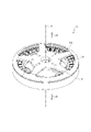
- FIG. 1 is a perspective view schematically showing the configuration of a motor according to an embodiment of the invention
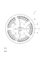
- FIG. FIG. 2 is a plan view of the motor shown in FIG. 1
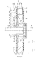
- 2 is a side sectional view of the motor shown in FIG. 1;
- FIG. 1 is a cross-sectional view schematically showing the configuration of a motor 1 according to an embodiment of the invention.
- FIG. 2 is a plan view of the motor 1.
- FIG. 3 is a side sectional view of the motor 1.
- the direction in which the rotation axis x extends when the motor 1 rotates is defined as the axis x direction.
- the axis x direction is also referred to as the rotation axis direction.
- the direction of the arrow a in the direction of the axis x is defined as the upper side a
- the direction of the arrow b is defined as the lower side b.
- the direction away from the axis x is defined as the outer circumference c
- the direction toward the axis x (the direction of the arrow d in FIGS.
- the direction shown in FIG. 3 is the side surface of the motor 1 for convenience.
- the direction of viewing the motor 1 from the upper side a to the lower side b is referred to as a plane, and the direction viewed from the lower side b to the upper side a is referred to as a bottom surface.
- the motor 1 is supported by a stator housing 11 having an inner peripheral portion 111 and an outer peripheral portion 112, and an outer peripheral portion 112 of the stator housing 11, and includes a stator core 120 and a coil 17.
- a stator 12 a rotor housing 13 covering the stator housing 11 and the stator 12 , and magnets 14 supported by an outer peripheral portion 132 of the rotor housing 13 .
- the stator 12 is provided inside the magnet 14 and faces the upper surface portion 121 of the stator core 120, which is the first surface positioned in the rotation axis direction while being supported by the stator housing 11, to the outside in the rotation axis direction. and a lower surface portion 122 which is a second surface.
- the magnet 14 has a top surface portion 141 which is a surface supported by the rotor housing 13 and is provided on the side of the top surface portion 121 of the stator core 120 in the rotation axis direction.
- the configuration and operation of the motor 1 will be specifically described below.
- the motor 1 includes the stator housing 11, the stator 12, the rotor housing 13, the magnets 14, and the bearings 16 as main components, as described above.
- the stator housing 11 has a bearing holder 114 and a connecting portion 115 in addition to the inner peripheral portion 111 and the outer peripheral portion 112 described above. As shown in FIG. 2, the stator housing 11 has the above-described inner peripheral portion 111 and outer peripheral portion 112 formed in an annular shape about the axis x.
- the inner peripheral portion 111 is formed in a cylindrical or substantially cylindrical shape extending in the direction of the axis x.
- the inner peripheral portion 111 has a bearing holder 114 that holds the bearing 16 on the surface on the inner peripheral side d.
- two bearing holders 114 are provided according to the number of bearings 16 .
- the bearing holder 114 holds the surface of the outer ring 161 of the bearing 16 on the outer peripheral side c.
- the outer peripheral portion 112 is formed in an annular shape or a substantially annular shape centered on the direction of the axis x.
- a connecting portion 115 is connected to the inner peripheral side d of the outer peripheral portion 112 .
- the inner peripheral surface portion 123 on the inner peripheral side d of the stator core 120 of the stator 12 faces the surface on the outer peripheral side c.
- Outer peripheral portion 112 has positioning portion 116 that positions upper surface portion 121, which is the first surface of stator core 120 of stator 12, in the direction of axis x.
- the positioning portion 116 is provided at the end portion of the upper side a of the outer peripheral portion 112 of the stator housing 11 in the direction of the axis x. Further, the positioning portion 116 protrudes from the surface of the outer peripheral portion 112 on the outer peripheral side c toward the outer peripheral side c in the radial direction. Positioning portion 116 positions stator core 120 in the direction of axis x by coming into contact with upper surface portion 121 of stator core 120 .
- the connecting portion 115 connects the inner peripheral portion 111 and the outer peripheral portion 112 .
- the connecting portion 115 extends radially from the inner peripheral portion 111 toward the outer peripheral portion 112, for example.
- the stator core 120 is a laminate of magnetic materials such as silicon steel plates.
- Stator core 120 is composed of an annular portion and tooth portions, which are a plurality of magnetic pole portions formed so as to extend from the annular portion toward the outer peripheral side c.
- the stator 12 is fixed to the stator housing 11 by fixing the inner peripheral surface portion 123 to the outer peripheral side c surface of the outer peripheral portion 112 of the stator housing 11 .
- An insulator serving as an insulating member is attached to the tooth portion of the stator core 120 .
- Coil 17 is wound around insulators mounted around each of the plurality of teeth. Stator core 120 and coil 17 are insulated by this insulator.
- the insulating member is not limited to an insulator as long as it insulates the stator core 120 and the coil 17. For example, an insulating coating, an insulating paper, an insulating sheet, or the like may be used.
- a magnet 14 is attached to the rotor housing 13 .
- the rotor housing 13 has a generally annular shape as a whole. As shown in FIG. 2, the rotor housing 13 has an inner peripheral portion 131 and an outer peripheral portion 132 formed in an annular shape about the axis x.
- the inner peripheral portion 131 is formed in a cylindrical or substantially cylindrical shape extending in the direction of the axis x.
- the inner peripheral portion 131 has a surface on the outer peripheral side c that is held by a surface on the inner peripheral side d of the inner ring 162 of the bearing 16 .
- the inner peripheral portion 131 functions as a rotating shaft in the motor 1 .
- the outer peripheral portion 132 is formed in an annular shape or a substantially annular shape centered on the direction of the axis x.
- a connecting portion 134 is connected to the inner peripheral side d of the outer peripheral portion 132 .
- the surface of the magnet 14 on the outer peripheral side c faces the surface on the inner peripheral side d.
- the rotor housing 13 is a surface on which the magnet 14 is supported by the rotor housing 13 in the direction of the axis x, and includes a positioning portion 133 that positions an upper surface portion 141 that is the surface of the upper side a.
- the positioning portion 133 is provided on the upper side a of the outer peripheral portion 132 of the rotor housing 13 in the direction of the axis x. Further, the positioning portion 133 protrudes from the surface of the outer peripheral portion 132 on the inner peripheral side d toward the inner peripheral side d in the radial direction. The positioning portion 133 positions the magnet 14 in the direction of the axis x by coming into contact with the upper surface portion 141 of the magnet 14 .
- the outer peripheral portion 132 of the rotor housing 13 is provided with a second positioning portion 135 for positioning the inner peripheral side d of the magnet 14 .
- the second positioning portion 135 protrudes downward b from the end of the positioning portion 133 on the inner peripheral side d.
- the connecting portion 134 connects the inner peripheral portion 131 and the outer peripheral portion 132 .
- the connecting portion 134 for example, radially extends from the inner peripheral portion 131 toward the outer peripheral portion 132 .
- a gap S is formed in the direction of the axis x between the upper surface portion 121 of the stator 12 and the lower surface b of the connecting portion 134 of the rotor housing 13 .
- the torque constant (Kt) that determines the characteristics of the motor is expressed by the following formula (1).
- R radius of rotation of the motor
- N number of coil turns
- b magnetic flux density
- L width of the magnetic path (length of the magnet in the direction of the axis x).
- the motor 1 it is common to change the magnetic path width (L) of the motor 1 when changing the torque constant by adjusting the numerical value of the above equation (1).
- the length of the stator core 120 in the stacking direction (axis x direction), specifically, the thickness of the stator core 120 is changed.
- a propeller (not shown) is attached to the top surface side (upper side a) of the stator 12, and the bottom side (lower side) of the rotor housing 13 facing it is attached.
- the face of side b) is attached to the fuselage, not shown.
- the stator 12 When assembling the motor 1, the stator 12 is assembled to the stator housing 11, and the magnet 14 is assembled to the rotor housing 13 from the axis x direction. Therefore, in the motor 1, the stator housing 11 needs a portion (positioning portion) for positioning the stator 12 in the direction of the axis x. Similarly, in the motor 1, the rotor housing 13 needs a positioning portion for positioning the magnet 14 in the direction of the axis x.
- the directions of the positioning surfaces of the stator core 120 and the magnet 14 in the direction of the axis x face each other.
- the positioning portion of the stator housing 11 may be provided on the lower side b in the direction of the axis x
- the positioning portion of the rotor housing 13 may be provided on the upper side a in the direction of the axis x.
- the positioning portion 116 for positioning the stator core 120 of the stator 12 in the x-axis direction and the positioning portion 133 for positioning the magnet 14 in the x-axis direction are both located on the lower side b. is facing That is, the positioning direction of the stator core 120 in the x-axis direction and the positioning direction of the magnet 14 in the x-axis direction match.
- the motor 1 when the thickness of the stator core 120 is changed, for example, even if the thickness of the stator core 120 is changed, the axis x direction of the magnet 14 and the stator core 120 can be adjusted. It is possible to prevent the center from shifting. That is, according to the motor 1, the positions of the centers of the stator core 120 and the magnet 14 in the direction of the axis x can be easily aligned.
- the motor 1 can maintain the gap between the rotor housing 13 and the stator core 120 even if the laminated thickness of the stator core 120 varies. It is possible to prevent the gap S from narrowing. In other words, according to the motor 1, the design space S can be designed to be narrow, so that the configuration can be miniaturized.
- both the positioning portion 116 and the positioning portion 133 are provided on the upper side a in the direction of the axis x, it is possible to reduce the size in the direction of the rotation axis.
Landscapes
- Engineering & Computer Science (AREA)
- Power Engineering (AREA)
- Permanent Magnet Type Synchronous Machine (AREA)
- Iron Core Of Rotating Electric Machines (AREA)
- Motor Or Generator Frames (AREA)
Abstract
Description
モータ1は、上述したように、主な構成要素として、ステータハウジング11、ステータ12、ロータハウジング13、マグネット14、及び、軸受16を備える。
次に、以上説明した構成を備えるモータ1の作用について説明する。
Claims (5)
- 内周部及び外周部を有するステータハウジングと、
前記ステータハウジングの外周部に支持されるステータと、
前記ステータハウジング及び前記ステータを覆うロータハウジングと、
前記ロータハウジングの外周部に支持されるマグネットと、
を備え、
前記ステータは、
前記マグネットの内側に設けられ、前記ステータハウジングに支持されるとともに回転軸方向において位置決めされる第1面と、回転軸方向において外部に対向する第2面と、
を有し、
前記マグネットは、
前記ロータハウジングに支持される面が、回転軸方向において前記ステータの第1面の側に設けられている、
モータ。 - 前記ステータの第1面と前記ロータハウジングとの間には、回転軸方向において空隙が形成されている、
請求項1に記載のモータ。 - 前記ステータハウジングは、
回転軸方向において前記ステータの第1面を位置決めする位置決め部を有する、
請求項1または2に記載のモータ。 - 前記ロータハウジングは、
回転軸方向において前記マグネットの前記ロータハウジングに支持される面を位置決めする位置決め部を備える、
請求項1から3のいずれか1項に記載のモータ。 - 前記ロータハウジングは、
前記位置決め部から回転軸方向に突出する第二位置決め部を有する、
請求項4に記載のモータ。
Priority Applications (2)
| Application Number | Priority Date | Filing Date | Title |
|---|---|---|---|
| US18/259,138 US20240055928A1 (en) | 2021-01-20 | 2021-12-16 | Motor |
| CN202180080120.5A CN116529987A (zh) | 2021-01-20 | 2021-12-16 | 马达 |
Applications Claiming Priority (2)
| Application Number | Priority Date | Filing Date | Title |
|---|---|---|---|
| JP2021-007349 | 2021-01-20 | ||
| JP2021007349A JP7724614B2 (ja) | 2021-01-20 | 2021-01-20 | モータ |
Publications (1)
| Publication Number | Publication Date |
|---|---|
| WO2022158184A1 true WO2022158184A1 (ja) | 2022-07-28 |
Family
ID=82548280
Family Applications (1)
| Application Number | Title | Priority Date | Filing Date |
|---|---|---|---|
| PCT/JP2021/046461 Ceased WO2022158184A1 (ja) | 2021-01-20 | 2021-12-16 | モータ |
Country Status (4)
| Country | Link |
|---|---|
| US (1) | US20240055928A1 (ja) |
| JP (1) | JP7724614B2 (ja) |
| CN (1) | CN116529987A (ja) |
| WO (1) | WO2022158184A1 (ja) |
Citations (3)
| Publication number | Priority date | Publication date | Assignee | Title |
|---|---|---|---|---|
| JPH0435670U (ja) * | 1990-07-24 | 1992-03-25 | ||
| JP2012222893A (ja) * | 2011-04-06 | 2012-11-12 | Tokyo Parts Ind Co Ltd | ブラシレスモータ |
| JP2019154082A (ja) * | 2016-07-15 | 2019-09-12 | デンソートリム株式会社 | 回転電機、そのステータ、およびそれらの製造方法 |
Family Cites Families (5)
| Publication number | Priority date | Publication date | Assignee | Title |
|---|---|---|---|---|
| JP2513812Y2 (ja) * | 1991-12-07 | 1996-10-09 | ミネベア株式会社 | アウタロ−タモ−タ |
| JP5777876B2 (ja) * | 2010-12-08 | 2015-09-09 | ミネベア株式会社 | ブラシレスモータおよびディスク駆動装置 |
| CN108496300B (zh) * | 2016-02-22 | 2022-05-27 | 深圳市大疆灵眸科技有限公司 | 电机位置感测 |
| JP6965228B2 (ja) * | 2018-10-30 | 2021-11-10 | ミネベアミツミ株式会社 | モータ |
| CN113839496A (zh) * | 2020-06-23 | 2021-12-24 | 尼得科电机(青岛)有限公司 | 电机外转子、无刷永磁电机和电气产品 |
-
2021
- 2021-01-20 JP JP2021007349A patent/JP7724614B2/ja active Active
- 2021-12-16 WO PCT/JP2021/046461 patent/WO2022158184A1/ja not_active Ceased
- 2021-12-16 US US18/259,138 patent/US20240055928A1/en active Pending
- 2021-12-16 CN CN202180080120.5A patent/CN116529987A/zh active Pending
Patent Citations (3)
| Publication number | Priority date | Publication date | Assignee | Title |
|---|---|---|---|---|
| JPH0435670U (ja) * | 1990-07-24 | 1992-03-25 | ||
| JP2012222893A (ja) * | 2011-04-06 | 2012-11-12 | Tokyo Parts Ind Co Ltd | ブラシレスモータ |
| JP2019154082A (ja) * | 2016-07-15 | 2019-09-12 | デンソートリム株式会社 | 回転電機、そのステータ、およびそれらの製造方法 |
Also Published As
| Publication number | Publication date |
|---|---|
| JP7724614B2 (ja) | 2025-08-18 |
| JP2022111728A (ja) | 2022-08-01 |
| CN116529987A (zh) | 2023-08-01 |
| US20240055928A1 (en) | 2024-02-15 |
Similar Documents
| Publication | Publication Date | Title |
|---|---|---|
| JPH1155902A (ja) | センサ組み込みモータの構造 | |
| JP5262583B2 (ja) | レゾルバ一体型回転電機及びロータコア | |
| EP3525320B1 (en) | Axial-gap type motor | |
| JP7678683B2 (ja) | モータ | |
| US20070080597A1 (en) | Motor and manufacturing method thereof | |
| JP2009195055A (ja) | 回転電機 | |
| WO2022158184A1 (ja) | モータ | |
| WO2018123839A1 (ja) | ロータ及びモータ | |
| JP6609138B2 (ja) | アキシャルギャップ型回転電機 | |
| JP2021069186A (ja) | 回転電機 | |
| US20240171022A1 (en) | Motor | |
| JP7269693B2 (ja) | ガルバノモータ | |
| JP2020088987A (ja) | ロータおよびモータ | |
| JP2020088988A (ja) | ロータおよびモータ | |
| CN111480281A (zh) | 电磁钢板、转子铁芯、转子以及马达 | |
| WO2023166550A1 (ja) | 同期リラクタンスモータの回転子 | |
| JP2007202363A (ja) | 回転電機 | |
| JP7533465B2 (ja) | ダイレクトドライブモータ | |
| JP2007129892A (ja) | モータ及びモータの製造方法 | |
| WO1994000904A1 (fr) | Moteur a induction a plusieurs niveaux | |
| JP5065877B2 (ja) | 電動機 | |
| JP4706298B2 (ja) | レゾルバ装置 | |
| US20220085670A1 (en) | Motor | |
| JP2024122508A (ja) | モータ | |
| JP2024013083A (ja) | リラクタンス回転電機 |
Legal Events
| Date | Code | Title | Description |
|---|---|---|---|
| 121 | Ep: the epo has been informed by wipo that ep was designated in this application |
Ref document number: 21921286 Country of ref document: EP Kind code of ref document: A1 |
|
| WWE | Wipo information: entry into national phase |
Ref document number: 202180080120.5 Country of ref document: CN |
|
| WWE | Wipo information: entry into national phase |
Ref document number: 18259138 Country of ref document: US |
|
| NENP | Non-entry into the national phase |
Ref country code: DE |
|
| 122 | Ep: pct application non-entry in european phase |
Ref document number: 21921286 Country of ref document: EP Kind code of ref document: A1 |