WO2022158181A1 - Soupape de moteur creuse - Google Patents
Soupape de moteur creuse Download PDFInfo
- Publication number
- WO2022158181A1 WO2022158181A1 PCT/JP2021/046409 JP2021046409W WO2022158181A1 WO 2022158181 A1 WO2022158181 A1 WO 2022158181A1 JP 2021046409 W JP2021046409 W JP 2021046409W WO 2022158181 A1 WO2022158181 A1 WO 2022158181A1
- Authority
- WO
- WIPO (PCT)
- Prior art keywords
- hollow
- engine valve
- shaft
- umbrella
- volume
- Prior art date
- Legal status (The legal status is an assumption and is not a legal conclusion. Google has not performed a legal analysis and makes no representation as to the accuracy of the status listed.)
- Ceased
Links
Images


Classifications
-
- F—MECHANICAL ENGINEERING; LIGHTING; HEATING; WEAPONS; BLASTING
- F01—MACHINES OR ENGINES IN GENERAL; ENGINE PLANTS IN GENERAL; STEAM ENGINES
- F01L—CYCLICALLY OPERATING VALVES FOR MACHINES OR ENGINES
- F01L3/00—Lift-valve, i.e. cut-off apparatus with closure members having at least a component of their opening and closing motion perpendicular to the closing faces; Parts or accessories thereof
- F01L3/02—Selecting particular materials for valve-members or valve-seats; Valve-members or valve-seats composed of two or more materials
- F01L3/04—Coated valve members or valve-seats
-
- F—MECHANICAL ENGINEERING; LIGHTING; HEATING; WEAPONS; BLASTING
- F01—MACHINES OR ENGINES IN GENERAL; ENGINE PLANTS IN GENERAL; STEAM ENGINES
- F01L—CYCLICALLY OPERATING VALVES FOR MACHINES OR ENGINES
- F01L3/00—Lift-valve, i.e. cut-off apparatus with closure members having at least a component of their opening and closing motion perpendicular to the closing faces; Parts or accessories thereof
- F01L3/12—Cooling of valves
- F01L3/14—Cooling of valves by means of a liquid or solid coolant, e.g. sodium, in a closed chamber in a valve
-
- F—MECHANICAL ENGINEERING; LIGHTING; HEATING; WEAPONS; BLASTING
- F01—MACHINES OR ENGINES IN GENERAL; ENGINE PLANTS IN GENERAL; STEAM ENGINES
- F01L—CYCLICALLY OPERATING VALVES FOR MACHINES OR ENGINES
- F01L3/00—Lift-valve, i.e. cut-off apparatus with closure members having at least a component of their opening and closing motion perpendicular to the closing faces; Parts or accessories thereof
- F01L3/20—Shapes or constructions of valve members, not provided for in preceding subgroups of this group
Definitions
- the present invention relates to hollow engine valves.
- engine valves for injecting intake gas into the combustion chamber of engines such as automobiles and ships and discharging exhaust gas are hollow engine valves in which a coolant such as metallic sodium is enclosed in the hollow part.
- a valve hereinafter also simply referred to as an engine valve (see Patent Document 1).
- the conventional design has a limited effect of suppressing the temperature rise.
- the present invention has been made in view of the above problems, and its object is to provide a hollow engine valve that can suppress the increase in temperature and maintain strength.
- a shaft portion and an umbrella portion that expands in diameter like an umbrella at one end of the shaft portion are provided, and at least in the hollow portion formed inside the shaft portion,
- the amount of the coolant enclosed is 0.3 or more with respect to the volume of the hollow portion.
- the amount of powdery or granular getter material to be enclosed in the hollow portion together with the coolant is 0.5 with respect to the remaining volume obtained by subtracting the volume of the coolant from the volume of the hollow portion. 1 g/cm 3 or more and 0.5 g/cm 3 or less.
- the presence of the getter material reduces the flow of the coolant. Since the movement of the coolant is not hindered and the residual gas in the hollow can be adsorbed (removed) to create a vacuum inside the hollow, the movement of the coolant inside the hollow becomes smooth and the vertical movement of the hollow engine valve is smoothed. It is possible to enhance the shaking effect of the coolant by
- the thickness of the shaft portion by reducing the thickness of the shaft portion to 0.8 mm to 1.0 mm, the heat dissipation performance of the shaft portion is improved, and the temperature rise of the hollow engine valve is suppressed. Strength can be maintained.
- one or both of the umbrella surface portion and the umbrella back portion of the umbrella portion are heat-insulated or heat-shielded.
- heat transfer from the combustion gas and the exhaust gas is prevented by performing heat insulation or shielding heat treatment on the head portion, which is susceptible to the heat of the combustion gas and the exhaust gas, and the hollow engine valve. It is possible to suppress the increase in temperature and maintain the strength of the hollow engine valve.
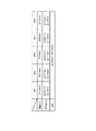
- FIG. 5 is a diagram showing the relationship between the amount of getter material enclosed in the hollow shaft engine valve and the temperature of the hollow shaft engine valve in the same demonstration experiment of the hollow shaft engine valve.
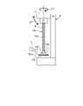
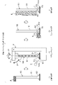
- FIG. 3 is a schematic diagram of a workpiece holding device and a thermal spraying device capable of applying a heat insulating or heat shielding coating to a shaft hollow engine valve. It is a schematic diagram which similarly shows the manufacturing process of a shaft hollow engine valve. It is a schematic diagram which similarly shows the manufacturing process of a shaft hollow engine valve.
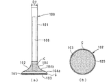
- a hollow shaft engine valve (hereinafter simply referred to as an engine valve) 100 is provided inside an intake port and an exhaust port communicating with a combustion chamber of an engine (not shown) of an automobile or the like, and is vertically oriented when the engine is actually running. to open and close the intake port and the exhaust port.
- the engine valve 100 enables intake gas to be supplied from the intake port into the combustion chamber by opening the intake port, and enables exhaust gas in the combustion chamber to be discharged from the exhaust port to the outside of the combustion chamber by opening the exhaust port.
- the engine valve 100 includes a round-bar-shaped shaft portion 101 and an umbrella portion 102 that is concentric with the lower end portion of the shaft portion 101 and expands in diameter like an umbrella.
- a hollow portion 106 is provided inside the shaft portion 101 .
- the umbrella portion 102 is formed by a disk-shaped umbrella front portion 103 on the lower surface side, a tapered umbrella back portion 104 on the upper surface side, and the thickness of the umbrella portion 102 between the umbrella front portion 103 and the umbrella back portion 104.
- Umbrella back portion 104 includes a face surface 104a that extends straight upward and in a centripetal direction from the upper portion of outer peripheral portion 105, and is continuously provided from the upper end of face surface 104a and curves upward and in a centripetal direction toward shaft portion 101. and a neck 104b extending inward.
- the surface of the head portion 102 excluding the face surface 104a of the engine valve 100 is provided with a coating portion C, which is heat-insulating.
- a material eg, ceramic
- the base material eg, SUS
- the coating portion C may be provided only on one surface of the umbrella front portion 103 or the umbrella back portion 104 . Further, when the coating portion C is provided on the umbrella back portion 104, the coating portion C may also be provided on the face surface 104a.
- the head portion 102 of the engine valve 100 may be subjected to heat shielding coating or mirror finishing (for example, Ra (arithmetic mean roughness) of 0.3 or less) instead of heat insulating coating. In this case, the engine valve 100 can obtain the same effect as when the head portion 102 is provided with a heat insulating coating. Also, depending on the part of the engine valve 100, the type of coating may be changed, or mirror finishing may be applied.
- the engine valve 100 includes a valve body 100a formed by a forging process and a shaft hollowing process, which will be described later, and a round bar-shaped shaft having the same diameter and material as the shaft portion 101a of the valve body 100a. and a shaft end member 100b fixed to the upper end of the portion 101a.
- a bottomed hollow portion 106 formed inside the shaft portion 101a of the valve body 100a is opened at the top by an opening portion 106b provided at the top portion of the shaft portion 101a.
- a powdery or granular getter material G for example, titanium powder
- a rod-shaped coolant for example, metallic sodium N
- the getter material G and metallic sodium N are hereinafter collectively referred to as "coolant, etc.”).
- the getter material G such as titanium is introduced into the hollow portion 106 together with the metallic sodium N, thereby removing the corrosive factors of the metallic sodium N and adsorbing (removing) residual gas in the hollow portion 106.
- the inside of the hollow portion 106 is evacuated. Thereby, the movement of the molten metallic sodium N inside the hollow portion 106 can be facilitated.
- the metallic sodium N becomes a liquid by being heated when the engine is actually running, and by moving up and down (shaking) in the hollow portion 106 in accordance with the movement of the engine valve 100, the heat received from the combustion chamber side is Heat can be efficiently transferred to the valve guide that guides the vertical movement of the engine valve 100 via the shaft portion 101 . That is, due to the shaking effect of metallic sodium N, the temperature rise (high temperature) of the engine valve 100 can be suppressed.
- the shaft end member 100b is fixed to the upper end portion of the shaft portion 101a of the valve body 100a by friction welding or the like to close the opening portion 106b.
- the hollow portion 106 is sealed, and the coolant and the like are enclosed in the hollow portion 106 .
- the shaft portion 101 a forms the shaft portion 101 of the engine valve 100 by being integrated (non-separable) with the shaft end member 100 b.
- An opening (not shown) for communicating the hollow portion 106 with the outside is provided in the canopy surface portion 103, and after the canopy surface portion 103 (opening) is turned upward and a coolant or the like is introduced through the opening, the The opening may be closed with a lid member (not shown).
- the hollow portion 106 has a hollow bottom portion 106a at its lower portion, and the position of the hollow bottom portion 106a is separated from the surface of the umbrella surface portion 103 by a distance D1 (for example, 1.0 mm to 3.0 mm). It is set to the position where Thereby, the shaking effect of the metallic sodium N can be exerted even on the umbrella surface portion 103 .
- a distance D1 for example, 1.0 mm to 3.0 mm
- engine valves 100 of types 1 to 5 (for example, about 90 mm to 130 mm in total length) used in passenger gasoline vehicles will be described.
- the hollow diameter D3 is set to ⁇ 3.0 mm to ⁇ 3.4 mm
- the hollow diameter D2 is set to ⁇ 5.5 mm.
- the hollow diameter D3 is set to ⁇ 3.5 mm to ⁇ 3.9 mm.
- the hollow diameter D3 is set to ⁇ 5.0 mm to ⁇ 5.4 mm.
- the thickness t of the hollow portion of the shaft portion 101 can be set to 0.8 mm to 1.0 mm.
- engine valves used in commercial diesel vehicles also have a wall thickness t of 0.8 mm to 1 mm due to the relationship between the shaft diameter D2 and the hollow diameter D3 as described above. 0 mm. That is, the relationship between the shaft diameter D2 and the hollow diameter D3 is not limited to the size of the engine valve.
- the heat dissipation performance of the shaft portion 101 can be improved.
- the cooling effect (heat removal effect) due to the shaking of the material G and the metallic sodium N can be enhanced.
- the engine valve 100 is prevented from becoming hot, and the strength of the engine valve 100 can be maintained.
- the specific value K was calculated based on the results of demonstration experiments regarding the cooling effect due to the difference in the amount of getter material G enclosed.
- the demonstration experiment related to the getter material G was performed in an environment equivalent to the environment of the engine valve 100 during actual engine operation.
- the temperatures of the head portion 103 and the head portion 104 of the engine valve 100 were as follows.
- the amount of the getter material G enclosed is 0 g
- the temperature of the umbrella front portion 103 is 668° C.
- the temperature of the umbrella back portion 104 is 669° C.
- the amount of the getter material G enclosed is 0.1 g/cm with respect to the remaining hollow volume.
- the temperature of the umbrella surface portion 103 is 647° C.
- the temperature of the umbrella back portion 104 is 643° C.
- the amount of the getter material G enclosed is 0.2 g/cm 3 with respect to the remaining hollow volume.
- the temperature of the portion 103 is 638° C.
- the temperature of the back portion 104 is 636° C.
- the amount of the getter material G enclosed is 0.3 g/cm 3 with respect to the remaining hollow volume
- the temperature of the top portion 103 is 637° C.
- the temperature of the umbrella back portion 104 is 635° C.
- the amount of getter material G enclosed is 0.4 g/cm 3 with respect to the remaining hollow volume
- the temperature of the umbrella front portion 103 is 633° C.
- the temperature of the umbrella back portion 104 is 633° C.
- the temperature of the umbrella front portion 103 is 637°C
- the temperature of the umbrella back portion 104 is 635°C.
- the amount of getter material G enclosed when comparing the cooling effect of each amount of getter material G enclosed with the case where the amount of getter material G enclosed is 0 g, the amount of getter material G enclosed is 0.1 g with respect to the remaining hollow volume. /cm 3 , the temperature difference from the case where the amount of getter material G is 0 g is ⁇ 21° C. for the umbrella front portion 103 and ⁇ 26° C. for the back portion 104. In the case of 0.2 g/cm 3 , the temperature difference from the case where the amount of getter material G is 0 g is ⁇ 30° C. for the canopy front portion 103 and ⁇ 33° C.
- the amount of getter material G enclosed is the remaining hollow volume.
- the temperature difference from the case where the amount of getter material G is 0 g is ⁇ 31° C. for the umbrella front portion 103 and ⁇ 34° C. for the back portion 104, and the amount of getter material G enclosed is In the case of 0.4 g/cm 3 with respect to the hollow residual volume, the temperature difference from the case where the amount of encapsulation is 0 g is -35° C. for the canopy front portion 103 and -37° C. for the canopy back portion 104 .
- the temperature difference from the case where the enclosed amount is 0 g is ⁇ 31° C. for the umbrella front portion 103 and ⁇ 34° C. for the umbrella back portion 104 .
- the temperature difference from the case where the amount of getter material G is 0 g is lower than ⁇ 20° C., and a clear cooling effect is obtained. Furthermore, in the range of 0.2 g/cm 3 to 0.5 g/cm 3 , the temperature difference from the case where the amount of inclusion was 0 g was lower than ⁇ 30° C., exhibiting a higher cooling effect.
- the optimum amount A1 of the getter material G to be filled is 0.1 g/cm 3 to 0.5 g/cm 3 (more preferably 0.2 g/cm 3 to 0.5 g/cm 3 ).
- the getter material G becomes metallic sodium. Since the movement of N is not hindered, the movement of metallic sodium N in the hollow portion 106 becomes smoother. As a result, it is possible to enhance the shaking effect of the coolant due to the vertical movement of the engine valve 100, so that the engine valve 100 can be prevented from becoming hot, and the strength of the engine valve 100 can be maintained.
- the optimum enclosed amount A1 of the getter material G can also be applied to a head hollow engine valve having a hollow head not only in the shaft portion but also in the head portion.
- the enclosed amount of metallic sodium N was set to 0.5 or more and 0.6 or less with respect to the volume ⁇ 1 of the hollow portion 106.
- the metallic sodium N itself Since it occupies half of the space in which N can move, it was not possible to move metallic sodium N efficiently. Therefore, the shaking effect of the engine valve 100 was not exhibited, and a sufficient cooling effect could not be obtained.
- the amount of metallic sodium N enclosed relative to the volume ⁇ 1 of the hollow portion 106 to be less than 0.5 (preferably 0.3, for example), A sufficient space in which the metallic sodium N can move can be secured in the hollow portion 106 .
- the shaking effect of the metallic sodium N can be enhanced, so that the temperature rise of the engine valve 100 can be suppressed, and the strength of the engine valve 100 can be maintained.
- the hollow portion 106 is provided only in the shaft portion 101, and the thickness t of the hollow portion of the shaft portion 101 is reduced within the range of ⁇ 0.8 mm to ⁇ 1.0 mm. , to improve the amount of heat transfer of the shaft portion 101 .
- This makes it possible to synergistically enhance the cooling effect by shaking the getter material G and the metallic sodium N whose enclosed amounts are optimized.
- by providing the coating portion C on the umbrella portion 102 where the hollow portion 106 is not provided heat transfer from the outside can be suppressed.
- the engine valve 100 enhances the cooling effect of the shaft portion 101 by shaking the metallic sodium N, and suppresses a rapid temperature rise of the head portion 102 due to heat insulation in the head portion 102. It becomes possible to suppress the temperature increase in the entirety of the engine valve 100, and the strength of the engine valve 100 can be maintained.
- a thermal spray apparatus S is provided which is capable of thermally spraying a material (eg, ceramic) onto a target workpiece.
- the work holding device H holds the engine valve 100 by fixing the upper end portion of the shaft portion 101 of the engine valve 100 with a holding portion H1 that is rotationally driven by a driving means (for example, a motor, not shown).
- a driving means for example, a motor, not shown.
- the thermal spraying device S thermally sprays ceramic or the like onto the engine valve 100, whereby the shaft portion 101 of the engine valve 100 is
- the canopy part 102 can be evenly coated except for the masking M applied to the head.
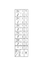
- a solid round bar (not shown) made of special steel having a predetermined shape (for example, cylindrical shape) is subjected to hot forging and heat treatment such as annealing. Execution to form a semi-finished product 200 shown in FIG. 6(1).
- the shaft diameter of shaft portion 201 and the shape and size of head portion 202 of semi-finished product 200 are substantially the same as those of shaft portion 101 and head portion 102 of engine valve 100, which is a finished product.
- the upper portion of the shaft portion 201 of the semi-finished product 200 is cut by a cutter CW, and as shown in FIG. 6(3), the cut upper end portion A hollow portion 106 is bored with a hollow drill D to form a valve body 100a.
- the thickness t of the shaft portion 101 is formed to be slightly thicker than 0.8 mm to 1.0 mm due to the scraping margin in the polishing process described later.
- the optimum amount of getter material G is introduced from the opening 106b of the hollow portion 106 of the valve body 100a.
- Metallic sodium N is inserted, and as shown in FIG. 6(5), the shaft end member 100b is fixed to the upper end portion of the shaft portion 101 of the valve body 100a by friction welding, thereby closing the opening 106b and supplying coolant and the like. is enclosed, and the engine valve 100 (before finishing) is molded.
- the polishing/coating process includes a polishing process for polishing each part of the engine valve 100 and a coating process for coating the head portion 102 of the engine valve 100 .
- the polishing step the upper end portion of the shaft portion 101 of the engine valve 100 is polished with a grindstone W, as shown in FIG. 7(1).
- the thermal spraying device S holds, for example, a ceramic solvent having a low thermal conductivity while being rotated appropriately in the S1 direction or the S2 direction by the work holding device H.
- a ceramic thermal spray coating is formed on the head portion 102 (head portion 103, head portion back portion 104) of the surface of the engine valve 100 where the masking M is not applied.
- Part C is suitably provided.
- the face surface 104a of the canopy back portion 104 of the engine valve 100 is polished with a whetstone W, as shown in FIG. 7(3).
- the face surface 104a abuts on the closed opening of each port. Polished.
- the polishing of the face surface 104a may be performed before the coating step shown in FIG. 7(2). That is, since the face surface 104a is coated after the surface treatment by polishing, it is finished without unevenness.
- the outer peripheral surface of the shaft portion 101 of the engine valve 100 is polished with a whetstone W, as shown in FIG. 7(4).
- the upper end portion polishing step shown in FIG. 7(1) and the shaft portion polishing step shown in FIG. 7(4) may be exchanged.
- the engine valve 100 of this embodiment is completed through the above steps.
Landscapes
- Engineering & Computer Science (AREA)
- Mechanical Engineering (AREA)
- General Engineering & Computer Science (AREA)
- Physics & Mathematics (AREA)
- Geometry (AREA)
- Lift Valve (AREA)
- Temperature-Responsive Valves (AREA)
Abstract
La présente invention concerne une soupape de moteur à arbre creux qui a une section d'arbre 101 et une section de parapluie 102 qui s'étend en diamètre à la manière d'un parapluie sur une extrémité de la section d'arbre 101, et dans laquelle un matériau de refroidissement N capable d'être sous une forme liquide et de se déplacer à travers une section creuse 106 par fusion à une température prescrite est scellé de manière étanche dans la section creuse 106 qui est creuse et est formée à l'intérieur de la section d'arbre 101, la quantité scellée de manière étanche du matériau de refroidissement N étant de 0,3 ou plus et inférieure à 0,5 par rapport au volume de la section creuse 106 ; et une quantité scellée de manière étanche d'une poudre ou d'un matériau getter sous forme de particules G scellé de manière étanche à l'intérieur de la section creuse 106 conjointement avec le matériau de refroidissement N étant de 0,1 g/cm3 à 0,5 g/cm3 par rapport au volume restant après soustraction du volume du matériau de refroidissement N au volume de la section creuse 106.
Applications Claiming Priority (2)
| Application Number | Priority Date | Filing Date | Title |
|---|---|---|---|
| JP2021009687A JP7687561B2 (ja) | 2021-01-25 | 2021-01-25 | 中空エンジンバルブ |
| JP2021-009687 | 2021-01-25 |
Publications (1)
| Publication Number | Publication Date |
|---|---|
| WO2022158181A1 true WO2022158181A1 (fr) | 2022-07-28 |
Family
ID=82549144
Family Applications (1)
| Application Number | Title | Priority Date | Filing Date |
|---|---|---|---|
| PCT/JP2021/046409 Ceased WO2022158181A1 (fr) | 2021-01-25 | 2021-12-16 | Soupape de moteur creuse |
Country Status (2)
| Country | Link |
|---|---|
| JP (1) | JP7687561B2 (fr) |
| WO (1) | WO2022158181A1 (fr) |
Cited By (1)
| Publication number | Priority date | Publication date | Assignee | Title |
|---|---|---|---|---|
| US20250277461A1 (en) * | 2022-10-25 | 2025-09-04 | Eaton Intelligent Power Limited | Systems and methods for engine valve cooling |
Citations (9)
| Publication number | Priority date | Publication date | Assignee | Title |
|---|---|---|---|---|
| JPH03260309A (ja) * | 1990-03-09 | 1991-11-20 | Fuji Oozx Kk | 内燃機関用流体冷却弁 |
| JPH0571316A (ja) * | 1991-05-21 | 1993-03-23 | Mitsubishi Materials Corp | 伝熱部材 |
| JPH08210112A (ja) * | 1994-10-31 | 1996-08-20 | Eaton Corp | 超軽量ポペット弁 |
| JP2003307105A (ja) * | 2002-04-12 | 2003-10-31 | Fuji Oozx Inc | エンジンバルブ |
| JP2004521229A (ja) * | 2001-04-07 | 2004-07-15 | フオルクスワーゲン・アクチエンゲゼルシヤフト | 直接噴射式内燃機関およびこの内燃機関の運転方法 |
| JP2010031828A (ja) * | 2008-06-24 | 2010-02-12 | Nissan Motor Co Ltd | エンジン用排気バルブ |
| CN101745813A (zh) * | 2009-12-11 | 2010-06-23 | 济南沃德汽车零部件有限公司 | 一种中空充钠气门及其制作方法 |
| JP2011179390A (ja) * | 2010-02-26 | 2011-09-15 | Mitsubishi Heavy Ind Ltd | エンジンバルブおよびこれを用いたエンジン |
| JP2021501283A (ja) * | 2017-10-30 | 2021-01-14 | フェデラル−モーグル バルブトレイン ゲーエムベーハーFederal−Mogul Valvetrain Gmbh | 内燃機関用の内部冷却バルブ |
Family Cites Families (3)
| Publication number | Priority date | Publication date | Assignee | Title |
|---|---|---|---|---|
| JPH0717908U (ja) * | 1993-09-08 | 1995-03-31 | 三菱自動車工業株式会社 | 内燃機関用中空弁 |
| CN101713306A (zh) * | 2009-03-20 | 2010-05-26 | 张明亮 | 内燃机中的空心气门 |
| WO2013145250A1 (fr) | 2012-03-30 | 2013-10-03 | 日鍛バルブ株式会社 | Procédé de fabrication d'une soupape à tige creuse contenant du réfrigérant, soupape à tige creuse contenant du réfrigérant, et système de logement de soupape |
-
2021
- 2021-01-25 JP JP2021009687A patent/JP7687561B2/ja active Active
- 2021-12-16 WO PCT/JP2021/046409 patent/WO2022158181A1/fr not_active Ceased
Patent Citations (9)
| Publication number | Priority date | Publication date | Assignee | Title |
|---|---|---|---|---|
| JPH03260309A (ja) * | 1990-03-09 | 1991-11-20 | Fuji Oozx Kk | 内燃機関用流体冷却弁 |
| JPH0571316A (ja) * | 1991-05-21 | 1993-03-23 | Mitsubishi Materials Corp | 伝熱部材 |
| JPH08210112A (ja) * | 1994-10-31 | 1996-08-20 | Eaton Corp | 超軽量ポペット弁 |
| JP2004521229A (ja) * | 2001-04-07 | 2004-07-15 | フオルクスワーゲン・アクチエンゲゼルシヤフト | 直接噴射式内燃機関およびこの内燃機関の運転方法 |
| JP2003307105A (ja) * | 2002-04-12 | 2003-10-31 | Fuji Oozx Inc | エンジンバルブ |
| JP2010031828A (ja) * | 2008-06-24 | 2010-02-12 | Nissan Motor Co Ltd | エンジン用排気バルブ |
| CN101745813A (zh) * | 2009-12-11 | 2010-06-23 | 济南沃德汽车零部件有限公司 | 一种中空充钠气门及其制作方法 |
| JP2011179390A (ja) * | 2010-02-26 | 2011-09-15 | Mitsubishi Heavy Ind Ltd | エンジンバルブおよびこれを用いたエンジン |
| JP2021501283A (ja) * | 2017-10-30 | 2021-01-14 | フェデラル−モーグル バルブトレイン ゲーエムベーハーFederal−Mogul Valvetrain Gmbh | 内燃機関用の内部冷却バルブ |
Cited By (1)
| Publication number | Priority date | Publication date | Assignee | Title |
|---|---|---|---|---|
| US20250277461A1 (en) * | 2022-10-25 | 2025-09-04 | Eaton Intelligent Power Limited | Systems and methods for engine valve cooling |
Also Published As
| Publication number | Publication date |
|---|---|
| JP2022113437A (ja) | 2022-08-04 |
| JP7687561B2 (ja) | 2025-06-03 |
Similar Documents
| Publication | Publication Date | Title |
|---|---|---|
| JPH08210112A (ja) | 超軽量ポペット弁 | |
| JP4678633B2 (ja) | 遠心減圧鋳造方法 | |
| WO2022158181A1 (fr) | Soupape de moteur creuse | |
| JP5880572B2 (ja) | シリンダブロックの製造方法 | |
| JP2006009080A (ja) | 摺動部材及び該摺動部材の表面処理方法 | |
| WO2014205291A2 (fr) | Joint d'huile pour clapet à manchon | |
| CN105917107A (zh) | 内燃机用活塞的制造装置及该活塞的制造方法 | |
| JP4451994B2 (ja) | 動弁機構の摺動部材及びその表面処理方法 | |
| EP3816422B1 (fr) | Procédé de fabrication de culasse, et matériau brut de culasse | |
| US20220206393A1 (en) | Transfer plate, method for manufacturing transfer plate, and substrate treating apparatus | |
| EP3887662B1 (fr) | Insert de chemise de cylindre à barrière thermique | |
| JP2022171663A (ja) | 成膜方法 | |
| JP2004068144A (ja) | アルミニウム合金鋳造部品の製造方法 | |
| CN106609370A (zh) | 金属压铸件的表面处理方法 | |
| JP2018197370A (ja) | 溶射膜の成膜方法 | |
| JP2022054836A (ja) | 成膜方法 | |
| US2436931A (en) | Method of preventing scaling during the forging of hollow metal articles | |
| US2893349A (en) | Apparatus for removing excess coating from a poppet valve | |
| US20220048130A1 (en) | Method for producing a welded cavity valve | |
| JP4618008B2 (ja) | カムシャフトの高周波焼入れ方法とその装置 | |
| US10583479B2 (en) | Automated bi-casting | |
| US20260108938A1 (en) | Apparatus and method of casting | |
| JPH03236460A (ja) | 直打式バルブリフタの溶射処理方法及びその装置 | |
| KR20250080050A (ko) | 표면 연마 방법 | |
| JP2007056793A (ja) | シリンダブロック及びシリンダブロックの製造方法 |
Legal Events
| Date | Code | Title | Description |
|---|---|---|---|
| 121 | Ep: the epo has been informed by wipo that ep was designated in this application |
Ref document number: 21921283 Country of ref document: EP Kind code of ref document: A1 |
|
| NENP | Non-entry into the national phase |
Ref country code: DE |
|
| 122 | Ep: pct application non-entry in european phase |
Ref document number: 21921283 Country of ref document: EP Kind code of ref document: A1 |