WO2022158181A1 - Hollow engine valve - Google Patents
Hollow engine valve Download PDFInfo
- Publication number
- WO2022158181A1 WO2022158181A1 PCT/JP2021/046409 JP2021046409W WO2022158181A1 WO 2022158181 A1 WO2022158181 A1 WO 2022158181A1 JP 2021046409 W JP2021046409 W JP 2021046409W WO 2022158181 A1 WO2022158181 A1 WO 2022158181A1
- Authority
- WO
- WIPO (PCT)
- Prior art keywords
- hollow
- engine valve
- shaft
- umbrella
- volume
- Prior art date
- Legal status (The legal status is an assumption and is not a legal conclusion. Google has not performed a legal analysis and makes no representation as to the accuracy of the status listed.)
- Ceased
Links
Images


Classifications
-
- F—MECHANICAL ENGINEERING; LIGHTING; HEATING; WEAPONS; BLASTING
- F01—MACHINES OR ENGINES IN GENERAL; ENGINE PLANTS IN GENERAL; STEAM ENGINES
- F01L—CYCLICALLY OPERATING VALVES FOR MACHINES OR ENGINES
- F01L3/00—Lift-valve, i.e. cut-off apparatus with closure members having at least a component of their opening and closing motion perpendicular to the closing faces; Parts or accessories thereof
- F01L3/02—Selecting particular materials for valve-members or valve-seats; Valve-members or valve-seats composed of two or more materials
- F01L3/04—Coated valve members or valve-seats
-
- F—MECHANICAL ENGINEERING; LIGHTING; HEATING; WEAPONS; BLASTING
- F01—MACHINES OR ENGINES IN GENERAL; ENGINE PLANTS IN GENERAL; STEAM ENGINES
- F01L—CYCLICALLY OPERATING VALVES FOR MACHINES OR ENGINES
- F01L3/00—Lift-valve, i.e. cut-off apparatus with closure members having at least a component of their opening and closing motion perpendicular to the closing faces; Parts or accessories thereof
- F01L3/12—Cooling of valves
- F01L3/14—Cooling of valves by means of a liquid or solid coolant, e.g. sodium, in a closed chamber in a valve
-
- F—MECHANICAL ENGINEERING; LIGHTING; HEATING; WEAPONS; BLASTING
- F01—MACHINES OR ENGINES IN GENERAL; ENGINE PLANTS IN GENERAL; STEAM ENGINES
- F01L—CYCLICALLY OPERATING VALVES FOR MACHINES OR ENGINES
- F01L3/00—Lift-valve, i.e. cut-off apparatus with closure members having at least a component of their opening and closing motion perpendicular to the closing faces; Parts or accessories thereof
- F01L3/20—Shapes or constructions of valve members, not provided for in preceding subgroups of this group
Definitions
- the present invention relates to hollow engine valves.
- engine valves for injecting intake gas into the combustion chamber of engines such as automobiles and ships and discharging exhaust gas are hollow engine valves in which a coolant such as metallic sodium is enclosed in the hollow part.
- a valve hereinafter also simply referred to as an engine valve (see Patent Document 1).
- the conventional design has a limited effect of suppressing the temperature rise.
- the present invention has been made in view of the above problems, and its object is to provide a hollow engine valve that can suppress the increase in temperature and maintain strength.
- a shaft portion and an umbrella portion that expands in diameter like an umbrella at one end of the shaft portion are provided, and at least in the hollow portion formed inside the shaft portion,
- the amount of the coolant enclosed is 0.3 or more with respect to the volume of the hollow portion.
- the amount of powdery or granular getter material to be enclosed in the hollow portion together with the coolant is 0.5 with respect to the remaining volume obtained by subtracting the volume of the coolant from the volume of the hollow portion. 1 g/cm 3 or more and 0.5 g/cm 3 or less.
- the presence of the getter material reduces the flow of the coolant. Since the movement of the coolant is not hindered and the residual gas in the hollow can be adsorbed (removed) to create a vacuum inside the hollow, the movement of the coolant inside the hollow becomes smooth and the vertical movement of the hollow engine valve is smoothed. It is possible to enhance the shaking effect of the coolant by
- the thickness of the shaft portion by reducing the thickness of the shaft portion to 0.8 mm to 1.0 mm, the heat dissipation performance of the shaft portion is improved, and the temperature rise of the hollow engine valve is suppressed. Strength can be maintained.
- one or both of the umbrella surface portion and the umbrella back portion of the umbrella portion are heat-insulated or heat-shielded.
- heat transfer from the combustion gas and the exhaust gas is prevented by performing heat insulation or shielding heat treatment on the head portion, which is susceptible to the heat of the combustion gas and the exhaust gas, and the hollow engine valve. It is possible to suppress the increase in temperature and maintain the strength of the hollow engine valve.
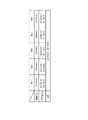
- FIG. 5 is a diagram showing the relationship between the amount of getter material enclosed in the hollow shaft engine valve and the temperature of the hollow shaft engine valve in the same demonstration experiment of the hollow shaft engine valve.
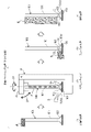
- FIG. 3 is a schematic diagram of a workpiece holding device and a thermal spraying device capable of applying a heat insulating or heat shielding coating to a shaft hollow engine valve. It is a schematic diagram which similarly shows the manufacturing process of a shaft hollow engine valve. It is a schematic diagram which similarly shows the manufacturing process of a shaft hollow engine valve.
- a hollow shaft engine valve (hereinafter simply referred to as an engine valve) 100 is provided inside an intake port and an exhaust port communicating with a combustion chamber of an engine (not shown) of an automobile or the like, and is vertically oriented when the engine is actually running. to open and close the intake port and the exhaust port.
- the engine valve 100 enables intake gas to be supplied from the intake port into the combustion chamber by opening the intake port, and enables exhaust gas in the combustion chamber to be discharged from the exhaust port to the outside of the combustion chamber by opening the exhaust port.
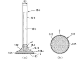
- the engine valve 100 includes a round-bar-shaped shaft portion 101 and an umbrella portion 102 that is concentric with the lower end portion of the shaft portion 101 and expands in diameter like an umbrella.
- a hollow portion 106 is provided inside the shaft portion 101 .
- the umbrella portion 102 is formed by a disk-shaped umbrella front portion 103 on the lower surface side, a tapered umbrella back portion 104 on the upper surface side, and the thickness of the umbrella portion 102 between the umbrella front portion 103 and the umbrella back portion 104.
- Umbrella back portion 104 includes a face surface 104a that extends straight upward and in a centripetal direction from the upper portion of outer peripheral portion 105, and is continuously provided from the upper end of face surface 104a and curves upward and in a centripetal direction toward shaft portion 101. and a neck 104b extending inward.
- the surface of the head portion 102 excluding the face surface 104a of the engine valve 100 is provided with a coating portion C, which is heat-insulating.
- a material eg, ceramic
- the base material eg, SUS
- the coating portion C may be provided only on one surface of the umbrella front portion 103 or the umbrella back portion 104 . Further, when the coating portion C is provided on the umbrella back portion 104, the coating portion C may also be provided on the face surface 104a.
- the head portion 102 of the engine valve 100 may be subjected to heat shielding coating or mirror finishing (for example, Ra (arithmetic mean roughness) of 0.3 or less) instead of heat insulating coating. In this case, the engine valve 100 can obtain the same effect as when the head portion 102 is provided with a heat insulating coating. Also, depending on the part of the engine valve 100, the type of coating may be changed, or mirror finishing may be applied.
- the engine valve 100 includes a valve body 100a formed by a forging process and a shaft hollowing process, which will be described later, and a round bar-shaped shaft having the same diameter and material as the shaft portion 101a of the valve body 100a. and a shaft end member 100b fixed to the upper end of the portion 101a.
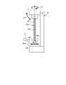
- a bottomed hollow portion 106 formed inside the shaft portion 101a of the valve body 100a is opened at the top by an opening portion 106b provided at the top portion of the shaft portion 101a.
- a powdery or granular getter material G for example, titanium powder
- a rod-shaped coolant for example, metallic sodium N
- the getter material G and metallic sodium N are hereinafter collectively referred to as "coolant, etc.”).
- the getter material G such as titanium is introduced into the hollow portion 106 together with the metallic sodium N, thereby removing the corrosive factors of the metallic sodium N and adsorbing (removing) residual gas in the hollow portion 106.
- the inside of the hollow portion 106 is evacuated. Thereby, the movement of the molten metallic sodium N inside the hollow portion 106 can be facilitated.
- the metallic sodium N becomes a liquid by being heated when the engine is actually running, and by moving up and down (shaking) in the hollow portion 106 in accordance with the movement of the engine valve 100, the heat received from the combustion chamber side is Heat can be efficiently transferred to the valve guide that guides the vertical movement of the engine valve 100 via the shaft portion 101 . That is, due to the shaking effect of metallic sodium N, the temperature rise (high temperature) of the engine valve 100 can be suppressed.
- the shaft end member 100b is fixed to the upper end portion of the shaft portion 101a of the valve body 100a by friction welding or the like to close the opening portion 106b.
- the hollow portion 106 is sealed, and the coolant and the like are enclosed in the hollow portion 106 .
- the shaft portion 101 a forms the shaft portion 101 of the engine valve 100 by being integrated (non-separable) with the shaft end member 100 b.
- An opening (not shown) for communicating the hollow portion 106 with the outside is provided in the canopy surface portion 103, and after the canopy surface portion 103 (opening) is turned upward and a coolant or the like is introduced through the opening, the The opening may be closed with a lid member (not shown).
- the hollow portion 106 has a hollow bottom portion 106a at its lower portion, and the position of the hollow bottom portion 106a is separated from the surface of the umbrella surface portion 103 by a distance D1 (for example, 1.0 mm to 3.0 mm). It is set to the position where Thereby, the shaking effect of the metallic sodium N can be exerted even on the umbrella surface portion 103 .
- a distance D1 for example, 1.0 mm to 3.0 mm
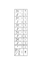
- engine valves 100 of types 1 to 5 (for example, about 90 mm to 130 mm in total length) used in passenger gasoline vehicles will be described.
- the hollow diameter D3 is set to ⁇ 3.0 mm to ⁇ 3.4 mm
- the hollow diameter D2 is set to ⁇ 5.5 mm.
- the hollow diameter D3 is set to ⁇ 3.5 mm to ⁇ 3.9 mm.
- the hollow diameter D3 is set to ⁇ 5.0 mm to ⁇ 5.4 mm.
- the thickness t of the hollow portion of the shaft portion 101 can be set to 0.8 mm to 1.0 mm.
- engine valves used in commercial diesel vehicles also have a wall thickness t of 0.8 mm to 1 mm due to the relationship between the shaft diameter D2 and the hollow diameter D3 as described above. 0 mm. That is, the relationship between the shaft diameter D2 and the hollow diameter D3 is not limited to the size of the engine valve.
- the heat dissipation performance of the shaft portion 101 can be improved.
- the cooling effect (heat removal effect) due to the shaking of the material G and the metallic sodium N can be enhanced.
- the engine valve 100 is prevented from becoming hot, and the strength of the engine valve 100 can be maintained.
- the specific value K was calculated based on the results of demonstration experiments regarding the cooling effect due to the difference in the amount of getter material G enclosed.
- the demonstration experiment related to the getter material G was performed in an environment equivalent to the environment of the engine valve 100 during actual engine operation.
- the temperatures of the head portion 103 and the head portion 104 of the engine valve 100 were as follows.
- the amount of the getter material G enclosed is 0 g
- the temperature of the umbrella front portion 103 is 668° C.
- the temperature of the umbrella back portion 104 is 669° C.
- the amount of the getter material G enclosed is 0.1 g/cm with respect to the remaining hollow volume.
- the temperature of the umbrella surface portion 103 is 647° C.
- the temperature of the umbrella back portion 104 is 643° C.
- the amount of the getter material G enclosed is 0.2 g/cm 3 with respect to the remaining hollow volume.
- the temperature of the portion 103 is 638° C.
- the temperature of the back portion 104 is 636° C.
- the amount of the getter material G enclosed is 0.3 g/cm 3 with respect to the remaining hollow volume
- the temperature of the top portion 103 is 637° C.
- the temperature of the umbrella back portion 104 is 635° C.
- the amount of getter material G enclosed is 0.4 g/cm 3 with respect to the remaining hollow volume
- the temperature of the umbrella front portion 103 is 633° C.
- the temperature of the umbrella back portion 104 is 633° C.
- the temperature of the umbrella front portion 103 is 637°C
- the temperature of the umbrella back portion 104 is 635°C.
- the amount of getter material G enclosed when comparing the cooling effect of each amount of getter material G enclosed with the case where the amount of getter material G enclosed is 0 g, the amount of getter material G enclosed is 0.1 g with respect to the remaining hollow volume. /cm 3 , the temperature difference from the case where the amount of getter material G is 0 g is ⁇ 21° C. for the umbrella front portion 103 and ⁇ 26° C. for the back portion 104. In the case of 0.2 g/cm 3 , the temperature difference from the case where the amount of getter material G is 0 g is ⁇ 30° C. for the canopy front portion 103 and ⁇ 33° C.
- the amount of getter material G enclosed is the remaining hollow volume.
- the temperature difference from the case where the amount of getter material G is 0 g is ⁇ 31° C. for the umbrella front portion 103 and ⁇ 34° C. for the back portion 104, and the amount of getter material G enclosed is In the case of 0.4 g/cm 3 with respect to the hollow residual volume, the temperature difference from the case where the amount of encapsulation is 0 g is -35° C. for the canopy front portion 103 and -37° C. for the canopy back portion 104 .
- the temperature difference from the case where the enclosed amount is 0 g is ⁇ 31° C. for the umbrella front portion 103 and ⁇ 34° C. for the umbrella back portion 104 .
- the temperature difference from the case where the amount of getter material G is 0 g is lower than ⁇ 20° C., and a clear cooling effect is obtained. Furthermore, in the range of 0.2 g/cm 3 to 0.5 g/cm 3 , the temperature difference from the case where the amount of inclusion was 0 g was lower than ⁇ 30° C., exhibiting a higher cooling effect.
- the optimum amount A1 of the getter material G to be filled is 0.1 g/cm 3 to 0.5 g/cm 3 (more preferably 0.2 g/cm 3 to 0.5 g/cm 3 ).
- the getter material G becomes metallic sodium. Since the movement of N is not hindered, the movement of metallic sodium N in the hollow portion 106 becomes smoother. As a result, it is possible to enhance the shaking effect of the coolant due to the vertical movement of the engine valve 100, so that the engine valve 100 can be prevented from becoming hot, and the strength of the engine valve 100 can be maintained.
- the optimum enclosed amount A1 of the getter material G can also be applied to a head hollow engine valve having a hollow head not only in the shaft portion but also in the head portion.
- the enclosed amount of metallic sodium N was set to 0.5 or more and 0.6 or less with respect to the volume ⁇ 1 of the hollow portion 106.
- the metallic sodium N itself Since it occupies half of the space in which N can move, it was not possible to move metallic sodium N efficiently. Therefore, the shaking effect of the engine valve 100 was not exhibited, and a sufficient cooling effect could not be obtained.
- the amount of metallic sodium N enclosed relative to the volume ⁇ 1 of the hollow portion 106 to be less than 0.5 (preferably 0.3, for example), A sufficient space in which the metallic sodium N can move can be secured in the hollow portion 106 .
- the shaking effect of the metallic sodium N can be enhanced, so that the temperature rise of the engine valve 100 can be suppressed, and the strength of the engine valve 100 can be maintained.
- the hollow portion 106 is provided only in the shaft portion 101, and the thickness t of the hollow portion of the shaft portion 101 is reduced within the range of ⁇ 0.8 mm to ⁇ 1.0 mm. , to improve the amount of heat transfer of the shaft portion 101 .
- This makes it possible to synergistically enhance the cooling effect by shaking the getter material G and the metallic sodium N whose enclosed amounts are optimized.
- by providing the coating portion C on the umbrella portion 102 where the hollow portion 106 is not provided heat transfer from the outside can be suppressed.
- the engine valve 100 enhances the cooling effect of the shaft portion 101 by shaking the metallic sodium N, and suppresses a rapid temperature rise of the head portion 102 due to heat insulation in the head portion 102. It becomes possible to suppress the temperature increase in the entirety of the engine valve 100, and the strength of the engine valve 100 can be maintained.
- a thermal spray apparatus S is provided which is capable of thermally spraying a material (eg, ceramic) onto a target workpiece.
- the work holding device H holds the engine valve 100 by fixing the upper end portion of the shaft portion 101 of the engine valve 100 with a holding portion H1 that is rotationally driven by a driving means (for example, a motor, not shown).
- a driving means for example, a motor, not shown.
- the thermal spraying device S thermally sprays ceramic or the like onto the engine valve 100, whereby the shaft portion 101 of the engine valve 100 is
- the canopy part 102 can be evenly coated except for the masking M applied to the head.
- a solid round bar (not shown) made of special steel having a predetermined shape (for example, cylindrical shape) is subjected to hot forging and heat treatment such as annealing. Execution to form a semi-finished product 200 shown in FIG. 6(1).
- the shaft diameter of shaft portion 201 and the shape and size of head portion 202 of semi-finished product 200 are substantially the same as those of shaft portion 101 and head portion 102 of engine valve 100, which is a finished product.
- the upper portion of the shaft portion 201 of the semi-finished product 200 is cut by a cutter CW, and as shown in FIG. 6(3), the cut upper end portion A hollow portion 106 is bored with a hollow drill D to form a valve body 100a.
- the thickness t of the shaft portion 101 is formed to be slightly thicker than 0.8 mm to 1.0 mm due to the scraping margin in the polishing process described later.
- the optimum amount of getter material G is introduced from the opening 106b of the hollow portion 106 of the valve body 100a.
- Metallic sodium N is inserted, and as shown in FIG. 6(5), the shaft end member 100b is fixed to the upper end portion of the shaft portion 101 of the valve body 100a by friction welding, thereby closing the opening 106b and supplying coolant and the like. is enclosed, and the engine valve 100 (before finishing) is molded.
- the polishing/coating process includes a polishing process for polishing each part of the engine valve 100 and a coating process for coating the head portion 102 of the engine valve 100 .
- the polishing step the upper end portion of the shaft portion 101 of the engine valve 100 is polished with a grindstone W, as shown in FIG. 7(1).
- the thermal spraying device S holds, for example, a ceramic solvent having a low thermal conductivity while being rotated appropriately in the S1 direction or the S2 direction by the work holding device H.
- a ceramic thermal spray coating is formed on the head portion 102 (head portion 103, head portion back portion 104) of the surface of the engine valve 100 where the masking M is not applied.
- Part C is suitably provided.
- the face surface 104a of the canopy back portion 104 of the engine valve 100 is polished with a whetstone W, as shown in FIG. 7(3).
- the face surface 104a abuts on the closed opening of each port. Polished.
- the polishing of the face surface 104a may be performed before the coating step shown in FIG. 7(2). That is, since the face surface 104a is coated after the surface treatment by polishing, it is finished without unevenness.
- the outer peripheral surface of the shaft portion 101 of the engine valve 100 is polished with a whetstone W, as shown in FIG. 7(4).
- the upper end portion polishing step shown in FIG. 7(1) and the shaft portion polishing step shown in FIG. 7(4) may be exchanged.
- the engine valve 100 of this embodiment is completed through the above steps.
Landscapes
- Engineering & Computer Science (AREA)
- Mechanical Engineering (AREA)
- General Engineering & Computer Science (AREA)
- Physics & Mathematics (AREA)
- Geometry (AREA)
- Lift Valve (AREA)
- Temperature-Responsive Valves (AREA)
Abstract
Description
本発明は、中空エンジンバルブに関する。 The present invention relates to hollow engine valves.
従来、自動車や船舶などのエンジンの燃焼室に吸気ガスを流入させ、排気ガスを排出させるためのエンジンバルブには、内部を中空にした中空部に、金属ナトリウムなどの冷却材を封入した中空エンジンバルブ(以下、単にエンジンバルブともいう)がある(特許文献1参照)。 Conventionally, engine valves for injecting intake gas into the combustion chamber of engines such as automobiles and ships and discharging exhaust gas are hollow engine valves in which a coolant such as metallic sodium is enclosed in the hollow part. There is a valve (hereinafter also simply referred to as an engine valve) (see Patent Document 1).
このようなエンジンバルブは、燃焼ガスや排気ガスに晒されることにより高温になるが、高温になるほどバルブ自体の強度が低下してしまうため、高温化を抑制するための設計が施されている。 Such engine valves become hot when exposed to combustion gas and exhaust gas, but the higher the temperature, the lower the strength of the valve itself.
しかしながら、軸部のみに中空を設けたこのようなエンジンバルブの場合、従来の設計では高温化の抑制効果に限りがある。例えば、エンジンバルブの性能を高めるために、軸部の肉厚を薄くしたり、傘内部まで中空にしてエンジンバルブの軽量化を図ることが考えられるが、単なる肉薄化では、熱容量が低下し急激な温度上昇によるバルブ突き上げやバルブ自体の強度が低下してしまうため、実用化が困難であった。 However, in the case of such an engine valve with a hollow only in the shaft portion, the conventional design has a limited effect of suppressing the temperature rise. For example, in order to improve the performance of engine valves, it is conceivable to reduce the thickness of the shaft or hollow the inside of the canopy to reduce the weight of the engine valve. It was difficult to put the valve into practical use because the valve was pushed up due to a large temperature rise and the strength of the valve itself decreased.
本発明は上記課題を鑑みてなされたものであり、その目的は、高温化を抑制し、強度の維持を図ることができる中空エンジンバルブを提供することである。 The present invention has been made in view of the above problems, and its object is to provide a hollow engine valve that can suppress the increase in temperature and maintain strength.
(1)本発明の第1の態様によれば、軸部及び前記軸部の一端に傘状に拡径する傘部を有し、少なくとも前記軸部の内部に形成した中空の中空部内に、所定の温度で融解して前記中空部内を液状となって移動可能な冷却材が封入される中空エンジンバルブにおいて、前記冷却材の封入量を、前記中空部の容積に対して0.3以上0.5未満とし、前記冷却材とともに前記中空部に封入する粉状又は粒状のゲッタ材の封入量を、前記中空部の容積から前記冷却材の体積を除いた残りの容積に対して、0.1g/cm3以上0.5g/cm3以下とする。 (1) According to the first aspect of the present invention, a shaft portion and an umbrella portion that expands in diameter like an umbrella at one end of the shaft portion are provided, and at least in the hollow portion formed inside the shaft portion, In a hollow engine valve in which a coolant that melts at a predetermined temperature and becomes liquid and moves in the hollow portion is enclosed, the amount of the coolant enclosed is 0.3 or more with respect to the volume of the hollow portion. 0.5, and the amount of powdery or granular getter material to be enclosed in the hollow portion together with the coolant is 0.5 with respect to the remaining volume obtained by subtracting the volume of the coolant from the volume of the hollow portion. 1 g/cm 3 or more and 0.5 g/cm 3 or less.
上記(1)の構成によれば、中空部内へ封入するゲッタ材の封入量を、冷却材が移動可能な中空部の容積に基づいて適切に設定することによって、ゲッタ材の存在により冷却材の移動が阻害されることなく、かつ中空部内の残存ガスを吸着(除去)して中空部内を真空とすることができるため、冷却材の中空部内の移動がスムーズになり、中空エンジンバルブの上下運動による冷却材のシェイキング効果を高めることができる。 According to the configuration (1) above, by appropriately setting the amount of the getter material to be enclosed in the hollow portion based on the volume of the hollow portion in which the coolant can move, the presence of the getter material reduces the flow of the coolant. Since the movement of the coolant is not hindered and the residual gas in the hollow can be adsorbed (removed) to create a vacuum inside the hollow, the movement of the coolant inside the hollow becomes smooth and the vertical movement of the hollow engine valve is smoothed. It is possible to enhance the shaking effect of the coolant by
これにより、冷却材の冷却効果を高めて中空エンジンバルブの高温化を抑制して、軸中空エンジンバルブの強度の維持を図ることができる。 As a result, it is possible to increase the cooling effect of the coolant, suppress the increase in temperature of the hollow engine valve, and maintain the strength of the hollow shaft engine valve.
(2)本発明の第2の態様によれば上記第1の態様において、前記軸部の軸径D2及び前記中空部の中空径D3が下記数式(1)の関係を有する。
(D2-D3)/2=0.8mm~1.0mm・・・(1)
(2) According to the second aspect of the present invention, in the above-described first aspect, the shaft diameter D2 of the shaft portion and the hollow diameter D3 of the hollow portion have the relationship of the following formula (1).
(D2-D3)/2=0.8 mm to 1.0 mm (1)
上記(2)の構成によれば、軸部の肉厚を0.8mm~1.0mmとして薄肉化することによって、軸部の放熱性能を向上させて、中空エンジンバルブの高温化を抑制し、強度の維持を図ることができる。 According to the above configuration (2), by reducing the thickness of the shaft portion to 0.8 mm to 1.0 mm, the heat dissipation performance of the shaft portion is improved, and the temperature rise of the hollow engine valve is suppressed. Strength can be maintained.
(3)本発明の第3の態様によれば上記第1の態様又は第2の態様において、前記傘部の傘表部と傘裏部のいずれか一方又は双方に断熱又は遮熱処理を行う。 (3) According to the third aspect of the present invention, in the first aspect or the second aspect, one or both of the umbrella surface portion and the umbrella back portion of the umbrella portion are heat-insulated or heat-shielded.
上記(3)の構成によれば、燃焼ガスや排気ガスの熱の影響を受けやすい傘部に断熱又は遮熱処理を行うことにより、燃焼ガスや排気ガスからの伝熱を防ぎ、中空エンジンバルブの高温化を抑制して、中空エンジンバルブの強度の維持を図ることができる。 According to the above configuration (3), heat transfer from the combustion gas and the exhaust gas is prevented by performing heat insulation or shielding heat treatment on the head portion, which is susceptible to the heat of the combustion gas and the exhaust gas, and the hollow engine valve. It is possible to suppress the increase in temperature and maintain the strength of the hollow engine valve.
本発明によれば、中空エンジンバルブの高温化を抑制し、強度の維持を図ることができる。 According to the present invention, it is possible to suppress the temperature rise of the hollow engine valve and maintain the strength.
(本実施形態)
以下、図1~図7を参照し、発明の一実施形態を通じて本発明を詳説するが、以下の実施形態は例示であり、特許請求の範囲に係る発明を限定するものではない。なお、軸中空エンジンバルブ100の方向については図1(a)の方向(上下左右)を基準として説明する。
(this embodiment)
Hereinafter, the present invention will be described in detail through one embodiment of the invention with reference to FIGS. The direction of the hollow
(軸中空エンジンバルブ100)
軸中空エンジンバルブ(以下、単にエンジンバルブという)100は、自動車等のエンジン(図示略)の燃焼室に連通する吸気ポート及び排気ポートの内部に設けられるものであって、エンジン実動時に上下方向へ移動して吸気ポート及び排気ポートを開閉可能とする。エンジンバルブ100は、吸気ポートを開放することによって吸気ガスを吸気ポートから燃焼室内に供給可能とし、排気ポートを開放することによって燃焼室内の排気ガスを排気ポートから燃焼室外に排出可能とする。
(Hollow shaft engine valve 100)
A hollow shaft engine valve (hereinafter simply referred to as an engine valve) 100 is provided inside an intake port and an exhaust port communicating with a combustion chamber of an engine (not shown) of an automobile or the like, and is vertically oriented when the engine is actually running. to open and close the intake port and the exhaust port. The
図1(a)に示すように、エンジンバルブ100は、丸棒状の軸部101と、軸部101の下端部に同心状かつ傘状に拡径した傘部102とを備える。軸部101の内部には中空の中空部106が設けられている。傘部102は、下面側の円板状の傘表部103と、上面側のテーパ状の傘裏部104と、傘表部103と傘裏部104との間に傘部102の厚みにより形成される外周部105とを有する。傘裏部104は、外周部105の上部から上方かつ求心方向に真っ直ぐ伸びるフェース面104aと、フェース面104aの上端部から連続して設けられ、軸部101に向かって、上方かつ求心方向に湾曲して伸びる首部104bとを有する。
As shown in FIG. 1(a), the
(コーティング部C)
図1(a)、(b)等のドットのハッチング領域に示すように、エンジンバルブ100のフェース面104aを除く傘部102の表面には、断熱コーティングが施されたコーティング部Cが設けられている。コーティング部Cには、エンジンバルブ100の基材(例えば、SUS)よりも熱伝導率の低い材質(例えば、セラミック)を採用する。
(Coating part C)
As shown in the hatched areas of dots in FIGS. 1(a) and 1(b), the surface of the
このように、傘部102の表面に断熱コーティングを施すことにより、燃焼ガス又は排気ガスに晒される比較的広面積の傘部102からの入熱を防ぐことができ、エンジンバルブ100の急激な温度上昇を抑制することができる。
By applying a heat-insulating coating to the surface of the
なお、コーティング部Cを、傘表部103又は傘裏部104のいずれか一方の表面にのみ設けてもよい。また、傘裏部104にコーティング部Cを設ける場合には、フェース面104aにもコーティング部Cを設けるようにしてもよい。
また、エンジンバルブ100の傘部102に対して、断熱コーティングの代わりに、遮熱コーティングや、鏡面加工(例えば、Ra(算術平均粗さ)0.3以下とする)を施してもよい。この場合、エンジンバルブ100は、傘部102に断熱コーティングを施した場合と同様の効果を得ることができる。また、エンジンバルブ100の部位に応じて、コーティングの種類を変更したり、鏡面加工を施すようにしてもよい。
Note that the coating portion C may be provided only on one surface of the umbrella
Also, the
(エンジンバルブ100の内部構造)
図2に示すように、エンジンバルブ100は、後述する鍛造工程及び軸中空加工工程によって成形されるバルブ本体100aと、バルブ本体100aの軸部101aと同径かつ同材質の丸棒状であって軸部101aの上端部に固着される軸端部材100bとから構成される。
(Internal structure of engine valve 100)
As shown in FIG. 2, the
バルブ本体100aの軸部101aの内部に形成された有底の中空部106は、軸部101の上部に設けた開口部106bによって上部が開放される。これにより、バルブ本体100aは、開口部106bから中空部106へ、粉状又は粒状のゲッタ材G(例えば、チタン粉末)が投入され、棒状の冷却材(例えば、金属ナトリウムN)が挿入され得るようになっている(以下、ゲッタ材G及び金属ナトリウムNをまとめて「冷却材等」という)。
A bottomed
ここで、チタン等のゲッタ材Gは、金属ナトリウムNとともに中空部106へ投入されることによって、金属ナトリウムNの腐食要因を除去するとともに、中空部106内の残存ガスを吸着(除去)して中空部106内を真空とする。これにより、融解した金属ナトリウムNの中空部106内の移動を円滑にすることができる。
Here, the getter material G such as titanium is introduced into the
また、金属ナトリウムNは、エンジン実動時は加熱されることにより液体となり、エンジンバルブ100の動きに合わせ中空部106内を上下移動(シェイキング)することにより、燃焼室側から受けた熱を、軸部101を介してエンジンバルブ100の上下運動をガイドするバルブガイドへ効率よく伝熱することができる。すなわち、金属ナトリウムNのシェイキング効果により、エンジンバルブ100の温度上昇(高温化)を抑制することができる。
In addition, the metallic sodium N becomes a liquid by being heated when the engine is actually running, and by moving up and down (shaking) in the
冷却材等を中空部106へ投入した後、軸端部材100bをバルブ本体100aの軸部101aの上端部に摩擦圧接等によって固着することにより開口部106bを閉塞する。これにより、中空部106は密閉され、冷却材等は中空部106内に封入される。また、軸部101aは軸端部材100bと一体的(分離不能)になって、エンジンバルブ100の軸部101を形成する。
After the coolant or the like is introduced into the
なお、中空部106と外部とを連通させる開口部(図示略)を傘表部103に設け、傘表部103(開口部)を上向きにして当該開口部から冷却材等を投入した後、当該開口部を蓋部材(図示略)により閉塞してもよい。
An opening (not shown) for communicating the
図2に示すように、中空部106は、下部に中空底部106aを設けており、中空底部106aの位置は、傘表部103の表面から距離D1(例えば、1.0mm~3.0mm)離間した位置に設定されている。これにより、金属ナトリウムNのシェイキング効果を傘表部103にまで及ぼすことができる。
As shown in FIG. 2, the
(軸径D2と中空径D3の関係)
図2に示すエンジンバルブ100における軸部101の外径D2(以下、軸径D2という)、及び中空部106の内径D3(以下、中空径D3という)の関係は、軸部101の中空部分の肉厚tが、0.8mm~1.0mmとなるように設定されている。
すなわち、以下の数式1の関係となっている。
[数1]
(D2-D3)/2=0.8mm~1.0mm
(Relationship between shaft diameter D2 and hollow diameter D3)
In the
That is, the relationship of the following
[Number 1]
(D2-D3)/2=0.8mm to 1.0mm
本実施形態の例として、乗用ガソリン車で使用される型1~型5のエンジンバルブ100(例えば、全長90mm~130mm程度)について説明する。
図3に示すように、軸径D2がφ5.0mmの型1のエンジンバルブ100においては、中空径D3がφ3.0mm~φ3.4mmに設定され、軸径D2がφ5.5mmの型2のエンジンバルブ100においては、中空径D3がφ3.5mm~φ3.9mmに設定され、軸径D2がφ6.0mmの型3のエンジンバルブ100においては、中空径D3がφ4.0mm~φ4.4mmに設定され、軸径D2がφ6.5mmの型4のエンジンバルブ100においては、中空径D3がφ4.5mm~φ4.9mmに設定され、軸径D2がφ7.0mmの型5のエンジンバルブ100においては、中空径D3がφ5.0mm~φ5.4mmに設定されるようになっている。このように軸径D2に応じて中空径D3を設定することにより、軸部101の中空部分の肉厚tを0.8mm~1.0mmとなるように設定することができる。
As an example of the present embodiment,
As shown in FIG. 3, in a
なお、商用ディーゼル車で使用されるエンジンバルブ(例えば、全長200mm程度、軸径φ12mm程度)にも、上記のように軸径D2と中空径D3との関係で肉厚tを0.8mm~1.0mmに設定することができる。すなわち、軸径D2と中空径D3との関係は、エンジンバルブのサイズに限定されることはない。 It should be noted that engine valves used in commercial diesel vehicles (for example, total length of about 200 mm, shaft diameter of about φ12 mm) also have a wall thickness t of 0.8 mm to 1 mm due to the relationship between the shaft diameter D2 and the hollow diameter D3 as described above. 0 mm. That is, the relationship between the shaft diameter D2 and the hollow diameter D3 is not limited to the size of the engine valve.
以上のように、軸部101の中空部分の肉厚tを上記の範囲の薄さにすることによって、軸部101の放熱性能を向上させることができ、後述する封入量が最適化されたゲッタ材G及び金属ナトリウムNのシェイキングによる冷却効果(脱熱効果)を高めることができる。これにより、エンジンバルブ100の高温化を抑制して、エンジンバルブ100の強度の維持を図ることができる。
As described above, by setting the thickness t of the hollow portion of the
(ゲッタ材Gの最適封入量)
本実施形態のエンジンバルブ100のゲッタ材Gの最適封入量A1は、中空部106の容積∨1から金属ナトリウムNの体積∨2を差引いた残りの中空部106の容積(以下、中空残存容積という)対比で、特定値K(0.1g/cm3以上0.5g/cm3以下)とする(下記数式2参照)。
[数2]
A1=K(∨1-∨2) K=0.1g/cm3~0.5g/cm3
(Optimum enclosed amount of getter material G)
The optimum enclosing amount A1 of the getter material G in the
[Number 2]
A1=K(∨1−∨2) K=0.1g/cm 3 to 0.5g/cm 3
特定値Kは、ゲッタ材Gの封入量の違いによる冷却効果に関する実証実験の結果に基づいて算出した。実証実験においては、図4に示すように、ゲッタ材Gの封入量を、特定値K=0(ゲッタ材Gを封入しない)から0.1g/cm3ずつ増加させて、K=0.5g/cm3まで検証を行った。
なお、ゲッタ材Gに係る実証実験は、実際のエンジン実動時におけるエンジンバルブ100の環境と同等の環境で実行した。
The specific value K was calculated based on the results of demonstration experiments regarding the cooling effect due to the difference in the amount of getter material G enclosed. In the demonstration experiment, as shown in FIG. 4, the amount of getter material G enclosed was increased by 0.1 g/cm 3 from a specific value K=0 (getter material G not enclosed), and K=0.5 g. / cm 3 .
In addition, the demonstration experiment related to the getter material G was performed in an environment equivalent to the environment of the
その結果、図4に示すように、エンジンバルブ100の傘表部103及び傘裏部104の温度は以下の通りとなった。
ゲッタ材Gの封入量が0gの場合は、傘表部103の温度は668℃、傘裏部104の温度は669℃、ゲッタ材Gの封入量が中空残存容積に対して0.1g/cm3の場合は、傘表部103の温度は647℃、傘裏部104の温度は643℃、ゲッタ材Gの封入量が中空残存容積に対して0.2g/cm3の場合は、傘表部103の温度は638℃、傘裏部104の温度は636℃、ゲッタ材Gの封入量が中空残存容積に対して0.3g/cm3の場合は、傘表部103の温度は637℃、傘裏部104の温度は635℃、ゲッタ材Gの封入量が中空残存容積に対して0.4g/cm3の場合は、傘表部103の温度は633℃、傘裏部104の温度は632℃、ゲッタ材Gの封入量が中空残存容積に対して0.5g/cm3の場合は、傘表部103の温度は637℃、傘裏部104の温度は635℃となった。
As a result, as shown in FIG. 4, the temperatures of the
When the amount of the getter material G enclosed is 0 g, the temperature of the
また、図4に示すように、ゲッタ材Gの各封入量における冷却効果を、封入量が0gの場合との比較でみると、ゲッタ材Gの封入量が中空残存容積に対して0.1g/cm3の場合、封入量が0gの場合との温度差は、傘表部103が-21℃、傘裏部104が-26℃となり、ゲッタ材Gの封入量が中空残存容積に対して0.2g/cm3の場合、封入量が0gの場合との温度差は、傘表部103が-30℃、傘裏部104が-33℃となり、ゲッタ材Gの封入量が中空残存容積に対して0.3g/cm3の場合、封入量が0gの場合との温度差は、傘表部103が-31℃、傘裏部104が-34℃となり、ゲッタ材Gの封入量が中空残存容積に対して0.4g/cm3の場合、封入量が0gの場合との温度差は、傘表部103が-35℃、傘裏部104が-37℃となり、ゲッタ材Gの封入量が中空残存容積に対して0.5g/cm3の場合、封入量が0gの場合との温度差は、傘表部103が-31℃、傘裏部104が-34℃となる。
Further, as shown in FIG. 4, when comparing the cooling effect of each amount of getter material G enclosed with the case where the amount of getter material G enclosed is 0 g, the amount of getter material G enclosed is 0.1 g with respect to the remaining hollow volume. /cm 3 , the temperature difference from the case where the amount of getter material G is 0 g is −21° C. for the
すなわち、ゲッタ材Gの封入量が中空残存容積に対して少なくとも0.1g/cm3以上であれば、封入量が0gの場合との温度差が-20℃よりも低くなって明らかな冷却効果を発揮し、更に0.2g/cm3~0.5g/cm3までは、封入量が0gの場合との温度差が-30℃よりも低くなってより高い冷却効果を発揮した。 That is, if the amount of getter material G enclosed is at least 0.1 g/cm 3 or more with respect to the remaining hollow volume, the temperature difference from the case where the amount of getter material G is 0 g is lower than −20° C., and a clear cooling effect is obtained. Furthermore, in the range of 0.2 g/cm 3 to 0.5 g/cm 3 , the temperature difference from the case where the amount of inclusion was 0 g was lower than −30° C., exhibiting a higher cooling effect.
以上の実証実験の結果から、ゲッタ材Gの最適封入量A1を、中空残存容積に対して特定値Kを0.1g/cm3~0.5g/cm3(より好ましくは0.2g/cm3~0.5g/cm3)とした。 From the results of the above demonstration experiments, the optimum amount A1 of the getter material G to be filled is 0.1 g/cm 3 to 0.5 g/cm 3 (more preferably 0.2 g/cm 3 to 0.5 g/cm 3 ).
以上のように、中空部106内へ封入するゲッタ材Gの封入量を、金属ナトリウムNが移動可能な中空部106の空間の容積に基づいて適切に設定することによって、ゲッタ材Gが金属ナトリウムNの移動を阻害することないため、金属ナトリウムNの中空部106内の移動がより円滑となる。これにより、エンジンバルブ100の上下運動による冷却材のシェイキング効果を高めることが可能となるため、エンジンバルブ100の高温化を抑制して、エンジンバルブ100の強度の維持を図ることができる。
As described above, by appropriately setting the amount of the getter material G to be enclosed in the
なお、ゲッタ材Gの最適封入量A1は、軸部だけでなく傘部にも中空を有する傘中空エンジンバルブにも適用することができる。 It should be noted that the optimum enclosed amount A1 of the getter material G can also be applied to a head hollow engine valve having a hollow head not only in the shaft portion but also in the head portion.
(金属ナトリウムNの最適封入量)
本実施形態のエンジンバルブ100の金属ナトリウムNの最適封入量A2を、中空部106の容積∨1に対して0.5未満(好ましくは、0.3)とする(下記数式3参照)。
[数3]
A2=∨1×0.3
(Optimum enclosed amount of metallic sodium N)
The optimum enclosed amount A2 of metallic sodium N in the
[Number 3]
A2=∨1×0.3
従来では、例えば、金属ナトリウムNの封入量を中空部106の容積∨1に対して0.5以上0.6以下としていたが、この場合、金属ナトリウムN自体が、中空部106内における金属ナトリウムNの移動可能な空間の半分を占めてしまうため、金属ナトリウムNを効率よく移動させることができなかった。そのため、エンジンバルブ100のシェイキング効果が発揮されず、十分な冷却効果を得ることができなかった。しかしながら、本実施形態のエンジンバルブ100においては、金属ナトリウムNの封入量を中空部106の容積∨1に対して0.5よりも少なくする(例えば、0.3が好適である)ことにより、中空部106内において金属ナトリウムNの移動可能な空間を十分に確保できる。これにより、金属ナトリウムNのシェイキング効果を高めることが可能となるため、エンジンバルブ100の高温化を抑制して、エンジンバルブ100の強度の維持を図ることができる。
Conventionally, for example, the enclosed amount of metallic sodium N was set to 0.5 or more and 0.6 or less with respect to the volume ∨1 of the
なお、金属ナトリウムNの最適封入量A2は、上記傘中空エンジンバルブにも適用することができる。 It should be noted that the optimum enclosed amount A2 of metallic sodium N can also be applied to the hollow head engine valve.
(冷却設計の全体最適化)
上記の通り、本実施形態のエンジンバルブ100は、軸部101のみに中空部106を設け、軸部101の中空部分の肉厚tをφ0.8mm~φ1.0mmの範囲で薄肉化することにより、軸部101の熱伝達量を向上させる。これにより、封入量が最適化されたゲッタ材G及び金属ナトリウムNのシェイキングによる冷却効果を相乗的に高めることができる。また、中空部106が設けられない傘部102にコーティング部Cを設けて、外部からの伝熱を抑制することができる。
(Overall optimization of cooling design)
As described above, in the
このように、エンジンバルブ100は、軸部101においては、金属ナトリウムNのシェイキングによる冷却効果を高め、傘部102においては、断熱による傘部102の急激な温度上昇を抑制することにより、エンジンバルブ100全体で高温化を抑制することが可能となり、エンジンバルブ100の強度の維持を図ることができる。
As described above, the
(コーティングに係る装置)
本実施形態では、エンジンバルブ100の傘部102をコーティングするために、図5に示すように、エンジンバルブ100を、複数方向に回転しうるように保持可能なワーク保持装置Hと、所定の被覆材料(例えばセラミック)を対象のワークへ溶射可能な溶射装置Sとを設ける。
(Apparatus related to coating)
In this embodiment, in order to coat the
ワーク保持装置Hは、エンジンバルブ100の軸部101の上端部を、駆動手段(例えば、モータ等、図示略)により回転駆動される保持部H1により固定することによって、エンジンバルブ100を、図5に示す軸部101の軸回りのS1方向、及び軸線方向に直行するS2方向に回転可能に保持することができる。
The work holding device H holds the
このように、ワーク保持装置Hによって、エンジンバルブ100をS1方向又はS2方向へ適宜回転させながら、溶射装置Sによって、セラミック等を当該エンジンバルブ100へ溶射することによって、エンジンバルブ100の軸部101に施されたマスキングMを除く傘部102をむら無くコーティングすることができる。
In this manner, while the
(エンジンバルブ100の製造方法)
本実施形態のエンジンバルブ100の鍛造工程では、所定の形状(例えば円柱状)の特殊鋼である中実丸棒(図示略)に対して熱間鍛造加工を施し、例えば焼鈍しなどの熱処理を実行して、図6(1)に示す半完成品200を成形する。なお、半完成品200の軸部201の軸径及び傘部202の形状及びサイズは、完成品であるエンジンバルブ100の軸部101と傘部102とほぼ同一である。
(Manufacturing method of engine valve 100)
In the forging process of the
次に、軸中空加工工程では、図6(2)に示すように、半完成品200の軸部201の上部をカッターCWにより切断し、図6(3)に示すように、切断した上端部から穴あけドリルDで中空部106を穿設し、バルブ本体100aを成形する。このとき、軸部101の肉厚tは0.8mm~1.0mmよりも、後述する研磨工程の削り代分、若干厚めに形成される。
Next, in the shaft hollowing process, as shown in FIG. 6(2), the upper portion of the
次に、冷却材等封入工程では、図6(4)に示すように、バルブ本体100aの中空部106の開口部106bから上記最適封入量のゲッタ材Gを投入した後、上記最適封入量の金属ナトリウムNを挿入し、図6(5)に示すように、バルブ本体100aの軸部101の上端部に、軸端部材100bを摩擦圧接により固着することで開口部106bを塞いで冷却材等を封入し、エンジンバルブ100(仕上げ前)を成形する。
Next, in the step of filling the coolant, etc., as shown in FIG. 6(4), the optimum amount of getter material G is introduced from the
次に、研磨・コーティング工程(仕上げ工程)では、エンジンバルブ100を部位毎に研磨する研磨工程と、エンジンバルブ100の傘部102をコーティングするコーティング工程から構成される。
研磨工程では、図7(1)に示すように、エンジンバルブ100の軸部101の上端部を砥石Wにより研磨する。
Next, the polishing/coating process (finishing process) includes a polishing process for polishing each part of the
In the polishing step, the upper end portion of the
次に、コーティング工程では、図7(2)に示すように、溶射装置Sが、例えば、熱伝導率の低いセラミック溶剤を、ワーク保持装置HによってS1方向又はS2方向へ適宜回転されながら保持されたエンジンバルブ100に対して溶射することにより、エンジンバルブ100の表面のうち、マスキングMが施されていない傘部102(傘表部103、傘裏部104)にセラミック溶射皮膜が形成され、コーティング部Cが適切に設けられる。
Next, in the coating step, as shown in FIG. 7(2), the thermal spraying device S holds, for example, a ceramic solvent having a low thermal conductivity while being rotated appropriately in the S1 direction or the S2 direction by the work holding device H. By thermally spraying the
再び、研磨工程では、図7(3)に示すように、エンジンバルブ100の傘裏部104のフェース面104aを砥石Wにより研磨する。フェース面104aは、エンジンバルブ100がエンジンの燃焼室における吸気ポートや排気ポートを閉塞する際に、各ポートの閉塞口に当接する面であるため、密閉性を要求され、不陸が無きように研磨される。
Again, in the polishing step, the
なお、フェース面104aの研磨を、図7(2)に示すコーティング工程の前に行うようにしてもよい。すなわち、フェース面104aは、研磨による下地処理後にコーティングされるため、不陸がないように仕上がる。
The polishing of the
最後の研磨工程では、マスキングMを除去した後、図7(4)に示すように、エンジンバルブ100の軸部101の外周面を砥石Wにより研磨する。なお、図7(1)に示す上端部研磨工程と、図7(4)に示す軸部研磨工程とを入れ替えてもよい。
本実施形態のエンジンバルブ100は、上記の工程により完成する。
In the final polishing step, after removing the masking M, the outer peripheral surface of the
The
C コーティング部 G ゲッタ材
H ワーク保持装置 M マスキング
N 金属ナトリウム S 溶射装置
W 砥石
100 軸中空エンジンバルブ 100a バルブ本体
100b 軸端部材 101 軸部
102 傘部 103 傘表部
104 傘裏部 104a フェース面
104b 首部 105 外周部
106 中空部 106a 中空底部
106b 開口部 200 半完成品
201 軸部 202 傘部
C Coating part G Getter material H Work holding device M Masking N Metal sodium S Thermal spraying
Claims (3)
前記冷却材の封入量を、前記中空部の容積に対して0.3以上0.5未満とし、
前記冷却材とともに前記中空部に封入する粉状又は粒状のゲッタ材の封入量を、前記中空部の容積から前記冷却材の体積を除いた残りの容積に対して、0.1g/cm3以上0.5g/cm3以下とすることを特徴とする中空エンジンバルブ。 It has a shaft portion and an umbrella portion that expands in diameter like an umbrella at one end of the shaft portion. In a hollow engine valve containing a movable coolant,
The amount of the coolant enclosed is set to 0.3 or more and less than 0.5 with respect to the volume of the hollow portion,
The amount of the powdery or granular getter material enclosed in the hollow portion together with the coolant is 0.1 g/cm 3 or more with respect to the volume of the hollow portion minus the volume of the coolant. A hollow engine valve characterized in that it is 0.5 g/cm 3 or less.
(D2-D3)/2=0.8mm~1.0mm・・・(1) 2. A hollow engine valve according to claim 1, wherein a shaft diameter D2 of said shaft portion and a hollow diameter D3 of said hollow portion have a relationship of the following formula (1).
(D2-D3)/2=0.8 mm to 1.0 mm (1)
Applications Claiming Priority (2)
| Application Number | Priority Date | Filing Date | Title |
|---|---|---|---|
| JP2021009687A JP7687561B2 (en) | 2021-01-25 | 2021-01-25 | Hollow Engine Valve |
| JP2021-009687 | 2021-01-25 |
Publications (1)
| Publication Number | Publication Date |
|---|---|
| WO2022158181A1 true WO2022158181A1 (en) | 2022-07-28 |
Family
ID=82549144
Family Applications (1)
| Application Number | Title | Priority Date | Filing Date |
|---|---|---|---|
| PCT/JP2021/046409 Ceased WO2022158181A1 (en) | 2021-01-25 | 2021-12-16 | Hollow engine valve |
Country Status (2)
| Country | Link |
|---|---|
| JP (1) | JP7687561B2 (en) |
| WO (1) | WO2022158181A1 (en) |
Cited By (1)
| Publication number | Priority date | Publication date | Assignee | Title |
|---|---|---|---|---|
| US20250277461A1 (en) * | 2022-10-25 | 2025-09-04 | Eaton Intelligent Power Limited | Systems and methods for engine valve cooling |
Citations (9)
| Publication number | Priority date | Publication date | Assignee | Title |
|---|---|---|---|---|
| JPH03260309A (en) * | 1990-03-09 | 1991-11-20 | Fuji Oozx Kk | Fluid cooling valve for internal combustion engine |
| JPH0571316A (en) * | 1991-05-21 | 1993-03-23 | Mitsubishi Materials Corp | Heat transfer member |
| JPH08210112A (en) * | 1994-10-31 | 1996-08-20 | Eaton Corp | Superlight weight poppet valve |
| JP2003307105A (en) * | 2002-04-12 | 2003-10-31 | Fuji Oozx Inc | Engine valve |
| JP2004521229A (en) * | 2001-04-07 | 2004-07-15 | フオルクスワーゲン・アクチエンゲゼルシヤフト | Direct injection type internal combustion engine and method of operating this internal combustion engine |
| JP2010031828A (en) * | 2008-06-24 | 2010-02-12 | Nissan Motor Co Ltd | Exhaust valve for engine |
| CN101745813A (en) * | 2009-12-11 | 2010-06-23 | 济南沃德汽车零部件有限公司 | Hollow sodium filling valve and manufacturing method thereof |
| JP2011179390A (en) * | 2010-02-26 | 2011-09-15 | Mitsubishi Heavy Ind Ltd | Engine valve and engine using the same |
| JP2021501283A (en) * | 2017-10-30 | 2021-01-14 | フェデラル−モーグル バルブトレイン ゲーエムベーハーFederal−Mogul Valvetrain Gmbh | Internal cooling valve for internal combustion engine |
Family Cites Families (3)
| Publication number | Priority date | Publication date | Assignee | Title |
|---|---|---|---|---|
| JPH0717908U (en) * | 1993-09-08 | 1995-03-31 | 三菱自動車工業株式会社 | Hollow valve for internal combustion engine |
| CN101713306A (en) * | 2009-03-20 | 2010-05-26 | 张明亮 | Hollow valve in internal-combustion engine |
| WO2013145250A1 (en) | 2012-03-30 | 2013-10-03 | 日鍛バルブ株式会社 | Method for manufacturing hollow poppet valve containing refrigerant, hollow poppet valve containing refrigerant, and valve-housing fixture |
-
2021
- 2021-01-25 JP JP2021009687A patent/JP7687561B2/en active Active
- 2021-12-16 WO PCT/JP2021/046409 patent/WO2022158181A1/en not_active Ceased
Patent Citations (9)
| Publication number | Priority date | Publication date | Assignee | Title |
|---|---|---|---|---|
| JPH03260309A (en) * | 1990-03-09 | 1991-11-20 | Fuji Oozx Kk | Fluid cooling valve for internal combustion engine |
| JPH0571316A (en) * | 1991-05-21 | 1993-03-23 | Mitsubishi Materials Corp | Heat transfer member |
| JPH08210112A (en) * | 1994-10-31 | 1996-08-20 | Eaton Corp | Superlight weight poppet valve |
| JP2004521229A (en) * | 2001-04-07 | 2004-07-15 | フオルクスワーゲン・アクチエンゲゼルシヤフト | Direct injection type internal combustion engine and method of operating this internal combustion engine |
| JP2003307105A (en) * | 2002-04-12 | 2003-10-31 | Fuji Oozx Inc | Engine valve |
| JP2010031828A (en) * | 2008-06-24 | 2010-02-12 | Nissan Motor Co Ltd | Exhaust valve for engine |
| CN101745813A (en) * | 2009-12-11 | 2010-06-23 | 济南沃德汽车零部件有限公司 | Hollow sodium filling valve and manufacturing method thereof |
| JP2011179390A (en) * | 2010-02-26 | 2011-09-15 | Mitsubishi Heavy Ind Ltd | Engine valve and engine using the same |
| JP2021501283A (en) * | 2017-10-30 | 2021-01-14 | フェデラル−モーグル バルブトレイン ゲーエムベーハーFederal−Mogul Valvetrain Gmbh | Internal cooling valve for internal combustion engine |
Cited By (1)
| Publication number | Priority date | Publication date | Assignee | Title |
|---|---|---|---|---|
| US20250277461A1 (en) * | 2022-10-25 | 2025-09-04 | Eaton Intelligent Power Limited | Systems and methods for engine valve cooling |
Also Published As
| Publication number | Publication date |
|---|---|
| JP2022113437A (en) | 2022-08-04 |
| JP7687561B2 (en) | 2025-06-03 |
Similar Documents
| Publication | Publication Date | Title |
|---|---|---|
| JPH08210112A (en) | Superlight weight poppet valve | |
| JP4678633B2 (en) | Centrifugal decompression casting method | |
| WO2022158181A1 (en) | Hollow engine valve | |
| JP5880572B2 (en) | Cylinder block manufacturing method | |
| JP2006009080A (en) | Sliding member and surface treatment method for the sliding member | |
| WO2014205291A2 (en) | Sleeve valve oil seal | |
| CN105917107A (en) | Piston manufacturing device for internal combustion engine and method of manufacturing the same | |
| JP4451994B2 (en) | Sliding member of valve operating mechanism and surface treatment method thereof | |
| EP3816422B1 (en) | Method for manufacturing cylinder head, and cylinder head rough material | |
| US20220206393A1 (en) | Transfer plate, method for manufacturing transfer plate, and substrate treating apparatus | |
| EP3887662B1 (en) | INSERT FOR THERMAL INSULATION CYLINDER LINING | |
| JP2022171663A (en) | Depositing method | |
| JP2004068144A (en) | Manufacturing method of aluminum alloy cast parts | |
| CN106609370A (en) | Surface treatment method for metal die casting | |
| JP2018197370A (en) | Thermal spray coating method | |
| JP2022054836A (en) | Film deposition method | |
| US2436931A (en) | Method of preventing scaling during the forging of hollow metal articles | |
| US2893349A (en) | Apparatus for removing excess coating from a poppet valve | |
| US20220048130A1 (en) | Method for producing a welded cavity valve | |
| JP4618008B2 (en) | Induction hardening method and apparatus for camshaft | |
| US10583479B2 (en) | Automated bi-casting | |
| US20260108938A1 (en) | Apparatus and method of casting | |
| JPH03236460A (en) | Method and device for directly thermal-spraying valve lifter | |
| KR20250080050A (en) | Method of polishing the surface | |
| JP2007056793A (en) | Cylinder block and cylinder block manufacturing method |
Legal Events
| Date | Code | Title | Description |
|---|---|---|---|
| 121 | Ep: the epo has been informed by wipo that ep was designated in this application |
Ref document number: 21921283 Country of ref document: EP Kind code of ref document: A1 |
|
| NENP | Non-entry into the national phase |
Ref country code: DE |
|
| 122 | Ep: pct application non-entry in european phase |
Ref document number: 21921283 Country of ref document: EP Kind code of ref document: A1 |