WO2022158077A1 - 部品搭載装置 - Google Patents
部品搭載装置 Download PDFInfo
- Publication number
- WO2022158077A1 WO2022158077A1 PCT/JP2021/039816 JP2021039816W WO2022158077A1 WO 2022158077 A1 WO2022158077 A1 WO 2022158077A1 JP 2021039816 W JP2021039816 W JP 2021039816W WO 2022158077 A1 WO2022158077 A1 WO 2022158077A1
- Authority
- WO
- WIPO (PCT)
- Prior art keywords
- cassette
- storage
- tape
- roll body
- receiving
- Prior art date
Links
- 239000000758 substrate Substances 0.000 claims description 10
- 238000000034 method Methods 0.000 description 13
- 238000003780 insertion Methods 0.000 description 7
- 230000037431 insertion Effects 0.000 description 7
- 238000012546 transfer Methods 0.000 description 5
- 230000007246 mechanism Effects 0.000 description 4
- 230000002093 peripheral effect Effects 0.000 description 3
- 238000011143 downstream manufacturing Methods 0.000 description 2
- 125000006850 spacer group Chemical group 0.000 description 2
- 238000011144 upstream manufacturing Methods 0.000 description 2
- 238000004804 winding Methods 0.000 description 2
- 238000013459 approach Methods 0.000 description 1
- 238000005452 bending Methods 0.000 description 1
- 230000005484 gravity Effects 0.000 description 1
- 238000004519 manufacturing process Methods 0.000 description 1
- 238000012986 modification Methods 0.000 description 1
- 230000004048 modification Effects 0.000 description 1
- 230000008569 process Effects 0.000 description 1
Images


Classifications
-
- H—ELECTRICITY
- H05—ELECTRIC TECHNIQUES NOT OTHERWISE PROVIDED FOR
- H05K—PRINTED CIRCUITS; CASINGS OR CONSTRUCTIONAL DETAILS OF ELECTRIC APPARATUS; MANUFACTURE OF ASSEMBLAGES OF ELECTRICAL COMPONENTS
- H05K13/00—Apparatus or processes specially adapted for manufacturing or adjusting assemblages of electric components
- H05K13/04—Mounting of components, e.g. of leadless components
- H05K13/0417—Feeding with belts or tapes
- H05K13/0419—Feeding with belts or tapes tape feeders
-
- B—PERFORMING OPERATIONS; TRANSPORTING
- B65—CONVEYING; PACKING; STORING; HANDLING THIN OR FILAMENTARY MATERIAL
- B65H—HANDLING THIN OR FILAMENTARY MATERIAL, e.g. SHEETS, WEBS, CABLES
- B65H19/00—Changing the web roll
- B65H19/10—Changing the web roll in unwinding mechanisms or in connection with unwinding operations
- B65H19/12—Lifting, transporting, or inserting the web roll; Removing empty core
-
- H—ELECTRICITY
- H05—ELECTRIC TECHNIQUES NOT OTHERWISE PROVIDED FOR
- H05K—PRINTED CIRCUITS; CASINGS OR CONSTRUCTIONAL DETAILS OF ELECTRIC APPARATUS; MANUFACTURE OF ASSEMBLAGES OF ELECTRICAL COMPONENTS
- H05K13/00—Apparatus or processes specially adapted for manufacturing or adjusting assemblages of electric components
- H05K13/02—Feeding of components
- H05K13/021—Loading or unloading of containers
-
- B—PERFORMING OPERATIONS; TRANSPORTING
- B65—CONVEYING; PACKING; STORING; HANDLING THIN OR FILAMENTARY MATERIAL
- B65H—HANDLING THIN OR FILAMENTARY MATERIAL, e.g. SHEETS, WEBS, CABLES
- B65H2701/00—Handled material; Storage means
- B65H2701/10—Handled articles or webs
- B65H2701/19—Specific article or web
- B65H2701/1942—Web supporting regularly spaced non-adhesive articles
Definitions
- the present disclosure relates to a component mounting device that picks up components from a carrier tape containing components and mounts them on a board.
- a tape feeder that conveys a carrier tape containing components and supplies the components to a predetermined component supply port is known as a component supply unit used in a component mounting apparatus that mounts components on a substrate.
- the carrier tape is wound around a core of a reel as a tape holder, and the carrier tape is transported, stored, set in a tape feeder, etc. while being wound around the reel.
- Patent Document 1 a roll body is stored in a case-shaped storage device with a part being opened, and the storage device storing the roll body can be installed side by side with a tape feeder.
- Patent Document 1 the mounting of the carrier tape for replenishment (replenishment tape) to the carriage of the storage device for the roll body is the storage of the roll body of the carrier tape (current tape feeder) actually being conveyed by the tape feeder. It is adapted to be cantilevered at the end of the device. For this reason, it has been difficult to deal with an increase in the size of the roll body due to insufficient strength and rigidity of the storage device.
- An object of the present disclosure is to provide a component mounting device that can cope with an increase in the size of the roll body.
- the component mounting apparatus of the present disclosure is a component mounting apparatus that picks up components from a carrier tape containing components and mounts them on a substrate, and includes a mounting head that picks up components and mounts them on the substrate, and a carrier tape roll.
- a storage cassette having a first storage space for storing and having a first opening capable of putting in and out a roll body in front, a storage cassette mounting part to which the storage cassette is mounted, and a first storage space for storing the roll body of the carrier tape. 2 storage spaces, a second opening is provided in front through which the roll body can be taken in and out, and a receiving cassette for storing the roll body supplied from the storage cassette mounted in the storage cassette mounting portion, and a receiving cassette are mounted.
- a receiving cassette mounting part that pulls out the carrier tape from the roll body of the receiving cassette mounted on the receiving cassette mounting part, supplies the parts to the mounting head, and continues to the carrier tape to the storage cassette mounted on the storage cassette mounting part.
- a component supply unit that pulls out the carrier tape from the roll body and supplies components to the mounting head.
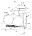
- FIG. 1 is a side view of a main part of a component mounting device equipped with a tape cassette according to one embodiment of the present disclosure.
- FIG. 2 is a side view of the component supply section of the component mounting apparatus according to the embodiment of the present disclosure;
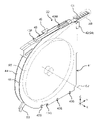
- FIG. 3 is a perspective view showing a tape cassette provided in a component mounting apparatus according to an embodiment of the present disclosure together with a roll of carrier tape stored therein.
- FIG. 4 is an enlarged perspective view of part of the carrier tape pulled out from the roll used in the component mounting apparatus according to the embodiment of the present disclosure.
- FIG. 5 is a side view showing components of a component supply section of the component mounting apparatus according to the embodiment of the present disclosure;
- FIG. 6 is a perspective view of a tape cassette according to one embodiment of the present disclosure;
- FIG. 7 is a side view of a tape cassette according to one embodiment of the present disclosure
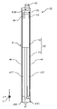
- FIG. FIG. 8 is a front view of a tape cassette according to one embodiment of the present disclosure
- FIG. 9 is an exploded perspective view of a tape cassette according to one embodiment of the present disclosure
- FIG. 10 is a side view of a frame included in a tape cassette according to one embodiment of the present disclosure
- FIG. 11 is a side sectional view of part of the component mounting apparatus according to one embodiment of the present disclosure.
- FIG. 12 is a side cross-sectional view of part of the component mounting apparatus according to one embodiment of the present disclosure.
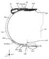
- FIG. 13 is a side cross-sectional view of a tape cassette according to one embodiment of the present disclosure;
- FIG. 13 is a side cross-sectional view of a tape cassette according to one embodiment of the present disclosure
- FIG. 14 is a side cross-sectional view of a tape cassette according to one embodiment of the present disclosure
- FIG. 15 is a side view of the shutter included in the tape cassette according to one embodiment of the present disclosure
- 16A is a cross-sectional view of a tape cassette according to one embodiment of the present disclosure
- FIG. 16B is a cross-sectional view of a tape cassette according to one embodiment of the present disclosure
- FIG. FIG. 16C is a cross-sectional view of a tape cassette according to one embodiment of the present disclosure
- 16D is a cross-sectional view of a tape cassette according to one embodiment of the present disclosure
- FIG. 16E is a cross-sectional view of a tape cassette according to one embodiment of the present disclosure
- FIG. 16A is a cross-sectional view of a tape cassette according to one embodiment of the present disclosure
- FIG. 16B is a cross-sectional view of a tape cassette according to one embodiment of the present disclosure
- FIG. 16C is a cross-sectional view of
- FIG. 16F is a cross-sectional view of a tape cassette according to one embodiment of the present disclosure
- FIG. 16G is a cross-sectional view of a tape cassette according to one embodiment of the present disclosure
- FIG. 17A is a side view of a tape cassette showing how a roll of carrier tape is put into and taken out of a storage cassette according to an embodiment of the present disclosure
- 17B is a side view of a tape cassette showing how a roll of carrier tape is put into and taken out of the storage cassette according to the embodiment of the present disclosure
- FIG. 17C is a side view of a tape cassette showing how a roll of carrier tape is put into and taken out of the storage cassette according to the embodiment of the present disclosure
- FIG. FIG. 17A is a side view of a tape cassette showing how a roll of carrier tape is put into and taken out of a storage cassette according to an embodiment of the present disclosure
- 17B is a side view of a tape cassette showing how a roll of carrier tape is put into and taken out of the storage cassette
- FIG. 18A is a front view of a plurality of types of tape cassettes with different width dimension in one embodiment of the present disclosure.
- FIG. 18B is a front view of a plurality of types of tape cassettes with different width dimension in one embodiment of the present disclosure.
- FIG. 18C is a front view of a plurality of types of tape cassettes with different width dimension in one embodiment of the present disclosure.
- FIG. 19 is a perspective view of an example of a tape cassette having the largest width dimension in one embodiment of the present disclosure.
- FIG. 20A is a side cross-sectional view of part of the component mounting device showing the mounting procedure of the tape cassette according to the embodiment of the present disclosure; FIG.
- FIG. 20B is a side cross-sectional view of part of the component mounting device showing the mounting procedure of the tape cassette according to the embodiment of the present disclosure
- FIG. 21A is a side cross-sectional view of part of the component mounting device showing how the roll body moves according to the embodiment of the present disclosure.
- FIG. 21B is a side cross-sectional view of part of the component mounting device showing how the roll body moves according to the embodiment of the present disclosure.
- FIG. 22A is a side cross-sectional view of part of the component mounting device showing the procedure for removing the tape cassette according to the embodiment of the present disclosure;
- FIG. 22B is a side cross-sectional view of part of the component mounting device showing the procedure for removing the tape cassette according to the embodiment of the present disclosure;
- FIG. 21A is a side cross-sectional view of part of the component mounting device showing the procedure for removing the tape cassette according to the embodiment of the present disclosure
- FIG. 22B is a side cross-sectional view of part of the component mounting device showing the procedure
- FIG. 23A is a side cross-sectional view of part of the component mounting device showing the mounting procedure of the tape cassette according to the embodiment of the present disclosure
- FIG. 23B is a side cross-sectional view of part of the component mounting device showing the mounting procedure of the tape cassette according to the embodiment of the present disclosure
- FIG. 24A is a side cross-sectional view of part of the component mounting device showing how the roll body moves according to the embodiment of the present disclosure
- FIG. 24B is a side cross-sectional view of part of the component mounting apparatus showing how the roll body moves according to the embodiment of the present disclosure
- FIG. 1 shows a main part side view of a component mounting apparatus 1T according to one embodiment of the present disclosure.
- the component mounting apparatus 1T is an apparatus for repeatedly executing a series of component mounting operations of mounting components BH on a board KB brought in from another apparatus in an upstream process and carrying out to another apparatus in a downstream process. It has a section 1A and a component supply section 1B.
- the component mounting apparatus main body 1A includes a base 11, a substrate transfer section 12, a mounting head 13, and a head moving mechanism 14.
- the substrate transfer unit 12 is composed of a conveyor mechanism, and horizontally transfers the substrate KB received from the apparatus of the upstream process and positions it at a predetermined working position.
- the direction in which the board KB is conveyed in the component mounting apparatus 1T is defined as the X direction (horizontal direction)
- the vertical direction is defined as the Z direction
- the direction orthogonal to both the X direction and the Z direction is defined as the Y direction (forward and backward direction). direction).
- the mounting head 13 has a plurality of downwardly extending nozzles 13N, and a vacuum suction force for sucking the component BH can be generated at the lower end of each nozzle 13N.
- the head moving mechanism 14 is composed of, for example, an XY table, and moves the mounting head 13 within the XY plane.
- FIG. 2 is a side view of the component supply section 1B of the component mounting device 1T.
- FIG. 3 is a perspective view showing the tape cassette 22 provided in the component mounting apparatus 1T together with the roll body RT of the carrier tape CT stored therein.
- FIG. 4 is an enlarged perspective view of part of the carrier tape CT pulled out from the roll body RT used in the component mounting apparatus 1T.
- FIG. 5 is a side view showing components of the component supply section 1B of the component mounting apparatus 1T. 1 and 2, the component supply section 1B has a carriage 21, a tape cassette 22 and a tape feeder 23. As shown in FIG.
- the tape cassette 22 can store a roll RT of the carrier tape CT (hereinafter simply referred to as the roll RT) in which the carrier tape CT is wound in a disk shape without a core (see also FIG. 3). . That is, the tape cassette 22 handles the roll body RT which is not wound on the reel.
- the roll RT of the carrier tape CT
- the carrier tape CT as shown in FIG. 4 (FIG. 4 is an enlarged view of the area AR in FIG. 3), has a base tape BT and a top tape TT.
- a large number of upwardly opening pockets PK are provided in the base tape BT in a row and at equal intervals in the longitudinal direction of the base tape BT.
- Each pocket PK stores a part BH.
- the top tape TT is attached to the upper surface of the base tape BT and encloses the component BH in the pocket PK.
- a plurality of feed holes SH are arranged in a row at regular intervals at positions parallel to the row of pockets PK of the base tape BT.
- the base 11 has a pair of carriage guide portions 11G extending rearward and facing in the X direction, and a pair of carriages extending rearward and facing in the X direction.
- a holding portion 11H is provided.
- a pair of carriage guide portions 11G are members that guide the left and right sides of the lower portion of the carriage 21 when the carriage 21 is connected to the base 11 .
- the pair of carriage holding portions 11H is a member that lifts and supports the left and right side portions of the carriage 21 that is guided by the carriage guide portion 11G and approaches the base 11 .
- a feeder base 31 is provided on the top of the carriage 21 .
- a feeder mounting slot 31S for mounting the tape feeder 23 is provided on the upper surface of the feeder base 31 so as to extend in the Y direction.
- the tape feeder 23 functions as a component supply unit that supplies components BH to the component mounting apparatus main body 1A, and slides a slide protrusion 23T (FIG. 5) provided on the bottom surface into the feeder mounting slot 31S of the feeder base 31. Thus, it can be attached to the feeder base 31 .
- the feeder base 31 is provided with a plurality of feeder mounting slots 31S arranged side by side in the X direction. Therefore, a plurality of tape feeders 23 can be mounted on the feeder base 31 side by side in the X direction.
- the truck 21 has a cassette mounting portion 33 formed in a flat plate shape as a whole at the rear portion (left side in each of these figures) of a truck base 32 movable on the floor FL.
- a pair of lower brackets 34 projecting upward are provided on the carriage base 32 at an intermediate portion in the front-rear direction so as to face each other in the X direction. Both ends of a lower support bar 35 extending in the X direction are supported by the pair of lower brackets 34 .
- a pair of upper brackets 36 projecting downward are provided facing each other in the X direction. Both ends of an upper support bar 37 extending in the X direction are supported by the pair of upper brackets 36 .
- the upper support bar 37 extends parallel to the lower support bar 35 above the lower support bar 35 (FIG. 5).
- FIG. 6 is a perspective view of the tape cassette 22.
- the tape cassette 22 has a case-shaped storage portion 41 and a shutter 42 as a regulation portion provided in the storage portion 41.
- the roll body RT is stored in a vertical posture.
- the “vertical posture” means a posture in which the center axis CJ of the disc-shaped roll body RT is substantially horizontal.
- the tape cassette 22 is used in two usage patterns in this embodiment.
- a first mode of use is used as a receiving portion for the roll body RT of the carrier tape CT (current tape) currently being conveyed by the tape feeder 23 , and the carriage base 32 and the cassette mounting portion 33 are straddled. be worn.
- the tape cassette 22 used as a receiving portion for the roll body RT of the current tape is hereinafter referred to as a "receiving cassette 22A" (FIGS. 2 and 5).
- a second mode of use of the tape cassette 22 is that it is used as a storage device for storing a roll body RT of carrier tape CT (supplementary tape) for replenishment when the current tape runs out of parts. It is attached to the carriage base 32 .
- the tape cassette 22 used as a storage device for such a roll body RT of replenishment tape is hereinafter referred to as a "storage cassette 22B" (FIGS. 2 and 5).
- the receiving cassette 22A and the storage cassette 22B are tape cassettes 22 having the same structure.
- Each tape feeder 23 mounted on the feeder base 31 is a so-called autoload feeder, and detects when the leading portion of the carrier tape CT is inserted from the tape entrance 23G (FIG. 2) provided at the rear end portion. to convey the carrier tape CT forward, and supply the component BH to the predetermined component supply port 23K. At this time, the tape feeder 23 feeds the carrier tape CT while pulling it out as a current tape from the roll body RT in the receiving cassette 22A.
- the leading end of the carrier tape CT (supplementary tape) pulled out from the roll body RT in the storage cassette 22B can be inserted into the tape inlet 23G of the tape feeder 23 before the current tape runs out.
- the tape feeder 23 detects that the trailing portion of the current tape has passed a predetermined position in the tape feeder 23, the tape feeder 23 starts feeding the supplementary tape.
- a plurality of carrier tapes CT are continuously conveyed without a break, and the components BH are supplied to the component mounting apparatus 1T without running out of components.
- the tape feeder 23 pulls out the carrier tape CT from the roll body RT of the receiving cassette 22A, supplies the components BH to the mounting head 13, and pulls out the carrier tape CT from the roll body RT of the storage cassette 22B following the carrier tape CT. It is a component supply unit that supplies components BH to the mounting head 13 .
- the board transfer section 12 When the component mounting apparatus 1T performs component mounting work, first, the board transfer section 12 operates to bring in the board KB from the outside and position it at a predetermined work position. When the substrate KB is positioned at the work position by the substrate transport section 12, the mounting turn is performed by interlocking the operation of the tape feeder 23 to supply the component BH to the component supply port 23K and the operation of the head moving mechanism 14 to move the mounting head 13. repeatedly.
- the mounting head 13 moves to a position above the tape feeder 23 and sucks (picks up) the component BH with the nozzle 13N, and then moves to a position above the board KB to mount the component BH on the board KB.
- Perform a series of actions When all the components BH to be mounted on the board KB are mounted by repeating the mounting turns, the board transfer section 12 is operated to unload the board KB to the equipment in the downstream process. This completes the component mounting work for each board KB.
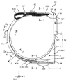
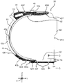
- FIG. 7 is a side view of the tape cassette 22.
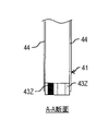
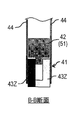
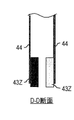
- FIG. FIG. 8 is a front view of the tape cassette 22.
- FIG. 9 is an exploded perspective view of the tape cassette 22.
- FIG. FIG. 10 is a side view of the frame 43 included in the tape cassette 22.
- the storage portion 41 includes a U-shaped frame 43 and a pair of plate members (side plates 44) mounted on both sides of the frame 43 in the width direction.
- a space surrounded by the U-shaped frame 43 and the pair of side plates 44 is a storage space 41S for storing the roll body RT.
- the opening of the U-shaped frame 43 faces forward, so that a front opening 41K is formed in front of the storage section 41 as an opening.
- the storage unit 41 includes a U-shaped frame 43 surrounding the storage space 41S and a pair of side plates 44 (plate members) fixed to the frame 43 covering the sides of the storage space 41S.
- the storage part 41 is configured to have a front opening 41K at the front facing the outer peripheral surface of the roll body RT.
- the frame 43 is composed of two frame members 43Z arranged in the width direction. As shown in FIGS. 9 and 10, the upper side of the frame 43 with the opening facing laterally is a frame upper portion 43a, and the lower side is a frame lower portion 43b. An arc-shaped guide portion 43c is provided between the frame upper portion 43a and the frame lower portion 43b.
- the frame upper portion 43a of the frame 43 is located facing the upper edge of the side plate 44.
- a frame lower portion 43 b of the frame 43 is positioned facing the lower edge of the side plate 44 .
- a shutter guide portion 43g (guide portion) is formed on the inner peripheral surface of the guide portion 43c and protrudes toward the center of the arc of the frame 43.
- a guide surface 43F is provided on the lower surface of the front end portion of the frame upper portion 43a and is inclined upward toward the front.
- the frame upper portion 43a is provided with an engaging groove 43M, a gripped portion 45 and a lower support bar engaging portion 43P in this order from the front end side.
- the engaging groove 43M is provided facing the upper surface of the frame upper portion 43a and opens forward.
- the gripped portion 45 is made of a block-shaped member.
- the frame lower portion 43b is provided with three pin insertion portions 43S arranged side by side in the Y direction.
- An upper support bar engaging portion 43Q is formed in a region between two front pin insertion portions 43S and one rear pin insertion portion 43S among the three pin insertion portions 43S.
- three storage cassette holding pins 33P are arranged in a row in the Y direction. These three storage cassette holding pins 33P constitute one cassette holding pin row 33L. A plurality of cassette holding pin rows 33L are arranged in the X direction on the upper surface of the cassette mounting portion 33 .
- one receiving cassette holding pin 33Q is provided in front of each cassette holding pin row 33L coaxially with the cassette holding pin row 33L. That is, on the upper surface of the cassette mounting portion 33, a plurality of pin rows in which three storage cassette holding pins 33P (cassette holding pin rows 33L) and one receiving cassette holding pin 33Q are arranged in a row are provided in the X direction.
- FIGS. 2 and 11 are side sectional views of part of the component mounting device 1T.
- the receiving cassette 22A is mounted on the carriage 21 with the storage cassette 22B turned upside down, that is, upside down.
- the lower support bar engaging portion 43P is engaged with the lower support bar 35
- the upper support bar engaging portion 43Q is supported on the upper side. It is engaged with the bar 37 and the engagement groove 43M is engaged with the receiving cassette holding pin 33Q.
- one receiving cassette holding pin 33Q, lower support bar 35, and upper support bar 37 form a receiving cassette mounting portion 38 (receiving portion mounting portion) to which the receiving cassette 22A is mounted.
- the tape cassette 22 has a sub-mounting portion 43R composed of an upper support bar engaging portion 43Q of a frame upper portion 43a and a frame lower portion 43b (FIGS. 10 and 11).
- the auxiliary mounting portion 43R By mounting the auxiliary mounting portion 43R to the receiving cassette mounting portion 38, the tape cassette 22 is mounted to the component mounting apparatus 1T as the receiving cassette 22A. In this manner, the receiving cassette mounting section 38 mounts the tape cassette 22 in an upside-down posture.
- the storage cassette 22B is configured such that three storage cassette holding pins 33P constituting one cassette holding pin row 33L are inserted into three pin insertion portions 43S provided in the frame lower portion 43b. and attached to the carriage 21 .
- the cassette holding pin row 33L (three storage cassette holding pins 33P arranged in a row in the Y direction) is connected to the storage cassette mounting portion 39 (storage device mounting portion) to which the storage cassette 22B is mounted. It has become.
- the tape cassette 22 has a main attachment portion 43U (attachment portion) constituted by a frame lower portion 43b (FIGS. 10 and 12). By attaching the main attachment portion 43U to the storage cassette attachment portion 39, the tape cassette 22 is attached to the component mounting apparatus 1T as the storage cassette 22B.
- the receiving cassette mounting section 38 mounts the receiving cassette 22A with the front opening 41K of the receiving cassette 22A facing the storage cassette mounting section 39.
- the storage cassette mounting section 39 mounts the storage cassette 22B with the front opening 41K of the storage cassette 22B facing the receiving cassette 22A mounted on the receiving cassette mounting section 38 .
- the receiving cassette 22A and the storing cassette 22B are mounted on the carriage 21 with the front opening 41K of the receiving cassette 22A and the front opening 41K of the storing cassette 22B facing each other. Therefore, it becomes possible to move the roll body RT stored in the storage cassette 22B to the receiving cassette 22A.
- the receiving cassette mounting section 38 mounts the receiving cassette 22A at a position lower than the storage cassette 22B mounted on the storage cassette mounting section 39 .
- the roll body RT is smoothly moved from the storage cassette 22B to the receiving cassette 22A, and the roll body RT stored in the receiving cassette 22A is prevented from moving to the storage cassette 22B.
- the receiving cassette mounting portion 38 mounts the receiving cassette 22A in an inclined posture that becomes lower as the distance from the storage cassette mounting portion 39 increases. As a result, the roll body RT is smoothly moved from the storage cassette 22B to the receiving cassette 22A, and the roll body RT stored in the receiving cassette 22A is prevented from moving to the storage cassette 22B.
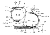
- FIG. 13 and 14 are side sectional views of the tape cassette 22.
- FIG. FIG. 15 is a side view of the shutter 42 provided in the tape cassette 22.
- FIG. 6, 13 and 14, the shutter 42 is provided within the storage space 41S of the storage section 41.
- the shutter 42 has a J-shape as a whole, and includes an arcuate slider portion 51 and a shutter tip portion 52 linearly extending from one end of the slider portion 51 .
- the slider portion 51 is connected to an operating lever 53 that protrudes outward (away from the center) of the arcuate slider portion 51 and is positioned to protrude rearward of the storage portion 41 .
- a tape holding portion 54 is provided at the tip of the shutter 42 (the end of the shutter tip 52).
- the tape holding portion 54 is a plate-like portion extending in the direction in which the shutter tip portion 52 extends.
- Two tape locking projections 55 as feed hole engaging portions protrude and extend from the tip of the tape holding portion 54 . These two tape locking projections 55 are arranged in parallel in a plane orthogonal to the width direction of the storage portion 41 .
- the shutter 42 is guided by the arc-shaped shutter guide portion 43 g provided on the frame 43 by the outer peripheral surface of the arc-shaped slider portion 51 .
- the shutter 42 is guided by the shutter guide portion 43g and slides in the inner region of the frame 43 in the rotational direction about the axis parallel to the X direction.
- the shutter 42 has a closed position (first position) that closes the front opening 41K of the storage section 41 at a position where the tip portion 52 of the shutter extends in the vertical direction (Z direction) at the front portion of the storage space 41S. Take (Fig. 13). Further, at a position where the shutter tip portion 52 extends in the front-rear direction (Y direction) under the storage space 41S, the front opening 41K of the storage portion 41 is opened (second position) (Fig. 14).
- the shutter 42 is positioned at the closed position, the roll body RT in the storage space 41S cannot pass through the front opening 41K and move out of the storage section 41 to the outside. However, when the shutter 42 is at the open position, the roll body RT in the storage space 41S can pass through the front opening 41K and move to the outside of the storage section 41 .
- an opening-side stopper surface 43T is formed at the front end of the frame lower portion 43b.
- a contact surface 52T which is an end surface of the shutter tip portion 52, is formed at the boundary between the slider portion 51 of the shutter 42 and the shutter tip portion 52 (FIG. 13).
- FIG. 16A to 16F are cross-sections of each part of the tape cassette 22 (sections AA, BB, CC, DD, and E in FIG. 13) when the shutter 42 is at the closed position. -E cross section and FF cross section).
- FIG. 16G is a partial cross section (GG cross section shown in FIG. 14) of the tape cassette 22 when the shutter 42 is at the open position.
- a closing side stopper surface 43K is formed at the upper end (rear end) of the frame lower portion 43b.
- the shutter 42 rotates counterclockwise in FIG. 14 (FIGS. 14 to 13) and reaches the closing position when the operating lever 53 comes into contact with the closing side stopper surface 43K. (Fig. 13).
- the operating lever 53 is an operating portion that performs an operation to displace the shutter 42 between the closed position (first position) and the open position (second position).
- FIG. 17A to 17C are side views of the tape cassette 22 showing how the roll body RT of the carrier tape CT is put into and taken out of the storage cassette 22B.
- the roll body RT is inserted from the front opening 41K of the storage section 41 with the shutter 42 positioned at the open position (arrow M1 shown in FIG. 17A).
- the operating lever 53 is moved downward (arrow N1 shown in FIG. 17B).
- the shutter 42 moves from the open position to the closed position, the front opening 41K of the storage section 41 is closed by the shutter 42, and the roll body RT is stored in the tape cassette 22 (FIG. 17B).
- the tape cassette 22 as a storage device includes a storage section 41 having a storage space 41S for storing the roll body RT and having a front opening 41K through which the roll body RT can be taken in and out. , a first position (closed position) in which at least a portion of the front opening 41K is closed to prevent the roll body RT stored in the storage space 41S from passing through the front opening 41K and moving to the outside of the storage section 41; and a second position (open position) that allows the roll body RT stored in the storage space to pass through the front opening 41K and move to the outside of the storage unit 41.
- the shutter 42 includes a slider portion 51 that slides while being guided by a shutter tip portion 52 positioned at the front opening 41K and a shutter guide portion 43g provided on the frame 43 when displaced to the closed position.
- the frame 43 is composed of two frame members 43Z (FIGS. 6 and 8). For this reason, one of the frame members 43Z has a thickness dimension corresponding to the widthwise dimension of the roll body RT, and the other is used in common regardless of the difference in the widthwise dimension of the roll body RT. It is possible to reduce the manufacturing cost of a plurality of types of tape cassettes 22 by sharing members.
- 18A, 18B and 18C are front views showing examples of multiple types of tape cassettes 22 having different width dimensions.
- FIG. 19 is a perspective view of an example of the tape cassette 22 having the largest widthwise dimension.
- FIG. 18A one of the two frame members 43Z is removed and one frame member 43Z is used in common. It can handle small cases.
- FIG. 18B by increasing the width dimension of one of the two frame members 43Z, it is possible to cope with the case where the width dimension of the roll body RT is larger than in the case described above.
- FIG. 18C two frame members 43Z are connected by a rod-shaped spacer SP so as to accommodate a roll body RT having a width dimension larger than that in FIG. 18B (see also FIG. 19). reference).
- the two frame members 43Z connected by the spacer SP are used in common.
- the gripped portion 45 is provided on each of the two frame members 43Z. This is because when the gripped portion 45 is gripped and the tape cassette 22 is lifted, if the gripped portion 45 is provided only on one of the two frame members 43Z, the position of the center of gravity of the entire tape cassette 22 is determined. This is because it will be tilted from the vertical posture due to the relationship, and it will be difficult to perform the mounting work on the carriage 21 . Also, if one gripped portion 45 is gripped to force the tape cassette 22 into a vertical posture, an excessive bending moment acts on the gripped portion 45 and may damage the gripped portion 45 . be.
- the receiving cassette 22A is attached to the receiving cassette mounting portion 38 of the carriage 21, which is the receiving portion mounting portion.
- the operator When mounting the receiving cassette 22A to the receiving cassette mounting portion 38, the operator first positions the shutter 42 at the open position (second position) with the operation lever 53, and then turns the tape cassette 22 upside down. Then, the lower support bar engaging portion 43P provided on the frame upper portion 43a is engaged with the lower support bar 35, and the upper support bar engaging portion 43Q provided on the frame lower portion 43b is engaged with the upper support bar 37. Then, the engaging groove 43M provided in the frame upper portion 43a is engaged with the receiving cassette holding pin 33Q (FIGS. 11 to 12).
- the receiving cassette 22A When the receiving cassette 22A is mounted on the carriage 21, the tape cassette 22 is tilted forward and slightly downward, and the guide surface 43F provided on the frame upper portion 43a is substantially horizontal (see FIG. 12). ). Further, the shutter 42 of the receiving cassette 22A mounted on the carriage 21 is positioned at the open position (second position).
- the storage cassette 22B in which the roll body RT is stored is mounted on the storage cassette mounting portion 39 of the carriage 21.
- the shutter 42 of the storage cassette 22B is positioned at the closed position until immediately before the storage cassette 22B is attached to the storage cassette attachment portion 39, and the roll body is held by the tape holding portion 54 of the shutter 42 positioned at the closed position.
- the leading portion of the carrier tape CT pulled out from RT is held (FIG. 12).
- the holding of the leading portion of the carrier tape CT by the tape holding portion 54 is achieved by the two tape locking protrusions 55 provided on the tape holding portion 54 being provided at the leading portion of the carrier tape CT pulled out from the roll body RT. 6 and 12).
- the leading portion of the carrier tape CT is substantially horizontal.
- the tape holding portion 54 provided at the tip portion of the shutter 42 has two feeding hole engaging portions capable of engaging with the feeding holes SH of the carrier tape CT. It has two tape locking protrusions 55 . These tape locking projections 55 hold the carrier tape CT pulled out from the roll body RT. At this time, the leading portion of the carrier tape CT is in a horizontal posture. That is, when the shutter 42 is positioned (displaced) at the closed position (first position), the tape holding section 54 horizontally holds the carrier tape CT.
- the operator grips the gripped portion 45 provided on the frame upper portion 43a of the frame 43 (when there are two gripped portions 45, the two gripped portions 45), the storage cassette 22B is lifted. Then, the leading portion of the carrier tape CT held by the tape holding portion 54 is pinched with fingers and inserted into the tape inlet 23G at the rear end portion of the tape feeder 23 .
- FIG. 20A and 20B are side cross-sectional views of part of the component mounting device 1T showing the mounting procedure of the tape cassette 22.
- FIG. 20A After inserting the leading end of the carrier tape CT pulled out from the roll body RT into the tape inlet 23G of the tape feeder 23, the operator operates the operation lever 53 to position the shutter 42 at the open position.
- the storage cassette 22B is moved above the storage cassette mounting portion 39 (FIG. 20A).
- the storage cassette 22B is lowered, and the three storage cassette holding pins 33P constituting the cassette holding pin row 33L, which is the storage cassette mounting portion 39, are inserted into the three pin insertion portions 43S provided in the frame lower portion 43b of the storage cassette 22B. is inserted, the storage cassette 22B is mounted on the storage cassette mounting portion 39 (that is, on the carriage 21) (Fig. 20B).
- the front end 43E of the lower portion (frame lower portion 43b) of the storage cassette 22B is placed against the pair of tensions of the receiving cassette 22A mounted on the receiving cassette mounting portion 38. It is made to pass between the exit parts 44H (FIG. 20A ⁇ FIG. 20B).
- the lower end of the frame lower portion 43b is formed with a tapered surface 43D having a shape (a downward narrowing shape) that facilitates guiding the frame lower portion 43b between the pair of projecting portions 44H.
- the pair of storage cassettes 22B are mounted.
- the side plates 44 are located inside the pair of side plates 44 of the receiving cassette 22A (Fig. 20B).
- the storage cassette 22B is sandwiched between the pair of side plates 44 of the reception cassette 22A located in front of it, and its movement in the X direction (the direction of tilting to the side) is suppressed. stabilizes.
- the storage cassette mounting section 39 mounts the storage cassette 22B with at least part of the front opening 41K of the storage cassette 22B inserted into the front opening 41K of the receiving cassette 22A.
- the storage portion 41 of the tape cassette 22 includes a cassette holding pin row 33L (three storage cassette holding pins) which is a positioning portion of the carriage 21 (that is, the component mounting device 1T). 33P).
- the storage cassette 22B is positioned and held by a storage cassette mounting portion 39 consisting of a cassette holding pin row 33L (three storage cassette holding pins 33P).
- the storage cassette 22B held in the storage cassette mounting portion 39 is sandwiched between the pair of side plates 44 of the reception cassette 22A located in front of it, so that the storage cassette 22B is prevented from moving in the X direction (the direction of tilting sideways). It is supposed to be suppressed.
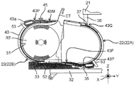
- 21A and 21B are side cross-sectional views of part of the component mounting apparatus 1T showing how the roll body RT moves.
- 22A and 22B are side cross-sectional views of part of the component mounting apparatus 1T showing the procedure for removing the tape cassette 22.
- the roll body RT stored in the storage cassette 22B is pulled by the carrier tape CT conveyed by the tape feeder 23 and rolls forward. It moves into the storage section 41 of the cassette 22A (Fig. 21A->Fig. 21B->Fig. 22A).
- the roll body RT moves from the storage cassette 22B into the receiving cassette 22A, the roll body RT is guided by the guiding surface 43F of the receiving cassette 22A. Also, the pair of side plates 44 of the storage cassette 22B are positioned inside the pair of side plates 44 of the receiving cassette 22A positioned in front thereof. Therefore, the roll body RT is smoothly moved and housed in the receiving cassette 22A (Fig. 21B ⁇ Fig. 22A).
- FIG. 23A and 23B are side cross-sectional views of part of the component mounting apparatus 1T showing the mounting procedure of the tape cassette 22.
- FIG. 23A When the roll body RT stored in the storage cassette 22B is moved into the receiving cassette 22A, the storage cassette 22B becomes empty.
- the empty storage cassette 22B is removed from the carriage 21 (cassette mounting portion 33) in order to mount the next replenishment tape roll RT (storage cassette 22B) on the carriage 21 (FIG. 22B).
- the operator mounts a new tape cassette 22 in the cassette mounting portion 33 according to the procedure described above (Fig. 23A->Fig. 23B).
- 24A and 24B are side cross-sectional views of part of the component mounting apparatus 1T showing how the roll body RT moves.
- the component mounting apparatus 1T can continue supplying the components BH by the tape feeder 23 while receiving the replenishment of the roll body RT (that is, the carrier tape CT).
- the carrier tape CT and its roll body RT that have not been used up by the component mounting apparatus 1T may remain in the receiving cassette 22A.
- the surplus roll body RT is stored or used in the component mounting apparatus 1T for producing another mounting board.
- the receiving cassette 22A is a tape cassette 22 that can be used as the storage cassette 22B
- the receiving cassette 22A containing the surplus roll body RT can be removed from the receiving cassette mounting portion 38 and stored as it is.
- the removed receiving cassette 22A is used as the storage cassette 22B.
- the winding direction of the roll body RT housed in the receiving cassette 22A is the same as the winding direction when used as the storage cassette 22B. Therefore, when using the receiving cassette 22A as the storage cassette 22B, it is possible to omit the work of taking out the roll body RT, reversing the orientation, and storing it again.
- the tape cassette 22 (storage device) in this embodiment supplies the roll body RT of the carrier tape CT containing the components BH to the component mounting device 1T. 42.
- the storage unit 41 has a storage space 41S for storing the roll body RT and a front opening 41K through which the roll body RT can be taken in and out.
- the shutter 42 has a closed position (first position) in which at least a portion of the front opening 41K is blocked to prevent the roll RT from passing through the front opening 41K and moving to the outside of the storage section 41; It is displaceable between an open position (second position) that allows the RT to pass through the front opening 41K and move to the outside of the storage section 41 .
- the tape cassette 22 as a storage device (storage cassette 22B) is mounted on the carriage 21 with the front opening 41K of the storage section 41 facing the component mounting device 1T, and the shutter 42 is positioned at the open position. Then, the roll body RT is supplied to the component mounting apparatus 1T.
- the roll body RT stored in the storage space 41S does not jump out of the storage space 41S when the shutter 42 is positioned at the closed position (first position). .
- the shutter 42 by positioning the shutter 42 at the open position (second position), it is possible to take out the stored roll RT to the outside of the storage space 41S. Therefore, according to the tape cassette 22 of the present embodiment, it is possible to reliably supply the roll body RT to the component mounting apparatus 1T while preventing the stored roll body RT from unexpectedly popping out.
- the component mounting apparatus 1T in the present embodiment includes a storage cassette mounting portion 39 (storage device mounting portion) to which is mounted a storage cassette 22B (storage device) in which the roll body RT of the carrier tape CT (supplementary tape) is stored. Then, the receiving cassette mounting portion 38 (receiving portion) is mounted with the receiving cassette 22A (receiving portion) for receiving the roll body RT supplied from the storage cassette 22B mounted in the storage cassette mounting portion 39 through the front opening 41K. It has a configuration with a part mounting part).
- the storage device for storing the roll body RT of the supplementary tape is attached to the storage device (receiving cassette 22A) for holding the roll body RT of the current tape. Instead, it is directly attached to the carriage 21 . Therefore, according to the component mounting apparatus 1T of the present embodiment, not only the small roll body RT but also the large roll body RT can be stably held and the component mounting work can be performed. That is, according to the component mounting apparatus 1T of the present embodiment, it is possible to easily deal with an increase in the size of the roll body.
- the component mounting apparatus 1T of the present embodiment it is possible to easily cope with an increase in the size of the roll body.
- the shutter 42 of the tape cassette 22 has a J-shape as a whole. As long as it can be displaced between the opening position (second position) at which the opening 41K is opened, it does not have to be J-shaped.
Landscapes
- Engineering & Computer Science (AREA)
- Manufacturing & Machinery (AREA)
- Microelectronics & Electronic Packaging (AREA)
- Supply And Installment Of Electrical Components (AREA)
Abstract
Description
13 搭載ヘッド
22 テープカセット
22A 受容カセット
22B 格納カセット(格納装置)
23 テープフィーダ(部品供給ユニット)
33P 格納カセット保持ピン(位置決め部)
38 受容カセット装着部(受容部装着部)
39 格納カセット装着部(格納装置装着部)
41 格納部
41K 正面開口(開口)
41S 格納空間
42 シャッタ(規制部)
43 フレーム
43g シャッタ案内部(案内部)
43S ピン挿入部(被係合部)
43U 主取り付け部(取り付け部)
43R 副取り付け部
44 側板(プレート部材)
51 スライダ部
52 シャッタ先端部(先端部)
53 操作レバー
54 テープ保持部
55 テープ係止突起(送り孔係合部)
CT キャリアテープ
SH 送り孔
RT ロール体
CJ 中心軸線
BH 部品
Claims (10)
- 部品を収納したキャリアテープから前記部品をピックアップして基板に搭載する部品搭載装置であって、
前記部品をピックアップして前記基板に搭載する搭載ヘッドと、
前記キャリアテープのロール体を格納する第1格納空間を有し、前方に前記ロール体を出し入れ可能な第1開口が設けられた格納カセットと、
前記格納カセットが装着される格納カセット装着部と、
前記キャリアテープの前記ロール体を格納する第2格納空間を有し、前方に前記ロール体を出し入れ可能な第2開口が設けられ、前記格納カセット装着部に装着された前記格納カセットから供給される前記ロール体を収納する受容カセットと、
前記受容カセットが装着される受容カセット装着部と、
前記受容カセット装着部に装着された前記受容カセットの前記ロール体から前記キャリアテープを引き出して前記搭載ヘッドに前記部品を供給し、前記キャリアテープに続けて前記格納カセット装着部に装着された前記格納カセットの前記ロール体から前記キャリアテープを引き出して前記搭載ヘッドに前記部品を供給する部品供給ユニットと、
を備えた、
部品搭載装置。 - 前記格納カセットは、前記ロール体を格納する前記第1格納空間を有するとともに前記第1開口が設けられた格納部と、前記第1開口の少なくとも一部を塞ぐことにより前記ロール体が前記第1開口を通過して前記第1格納空間の外部に移動するのを規制する第1の位置と、前記ロール体が前記第1開口を通過して前記第1格納空間の外部に移動するのを許容する第2の位置との間で変位する第1規制部と、を有する、
請求項1に記載の部品搭載装置。 - 前記受容カセット装着部は、前記受容カセットの前記第2開口を前記格納カセット装着部に向けて前記受容カセットを装着し、
前記格納カセット装着部は、前記格納カセットの前記第1開口を前記受容カセット装着部に装着された前記受容カセットに向けて前記格納カセットを装着する、
請求項1または2に記載の部品搭載装置。 - 前記格納カセット装着部は、前記格納カセットの前記第1開口の少なくとも一部を前記受容カセットの前記第2開口に挿入した状態で前記格納カセットを装着する、
請求項1から3のいずれか一項に記載の部品搭載装置。 - 前記受容カセット装着部は、前記格納カセット装着部に装着された前記格納カセットよりも低い位置に前記受容カセットを装着する、
請求項1から4のいずれか一項に記載の部品搭載装置。 - 前記受容カセット装着部は、前記格納カセット装着部から遠ざかるにつれて低くなる傾斜姿勢で前記受容カセットを装着する、
請求項1から5のいずれか一項に記載の部品搭載装置。 - 前記格納カセットと前記受容カセットとは同一構造を有するテープカセットである、
請求項1から6のいずれか一項に記載の部品搭載装置。 - 前記受容カセット装着部は、上下反転させた姿勢で前記テープカセットを装着する、
請求項7に記載の部品搭載装置。 - 前記格納カセットは、前記第1開口の少なくとも一部を塞ぐことにより前記ロール体が前記第1開口を通過して前記第1格納空間の外部に移動するのを規制する第3の位置と、前記ロール体が前記第1開口を通過して前記第1格納空間の外部に移動するのを許容する第4の位置との間で変位する第2規制部を有し、
前記受容カセット装着部に装着した前記受容カセットの前記第1規制部は前記第2の位置に位置し、前記格納カセット装着部に装着した前記格納カセットの前記第2規制部は前記第3の位置に位置する、
請求項7または8に記載の部品搭載装置。 - 前記搭載ヘッドを有する部品搭載装置本体部と、前記部品搭載装置本体部に着脱される台車とをさらに有し、
前記格納カセット装着部と前記受容カセット装着部とは前記台車に設けられている、
請求項1から9のいずれか一項に記載の部品搭載装置。
Priority Applications (3)
| Application Number | Priority Date | Filing Date | Title |
|---|---|---|---|
| DE112021006859.8T DE112021006859T5 (de) | 2021-01-21 | 2021-10-28 | Bauteil-Ladevorrichtung |
| JP2022576986A JPWO2022158077A1 (ja) | 2021-01-21 | 2021-10-28 | |
| CN202180091381.7A CN116784008A (zh) | 2021-01-21 | 2021-10-28 | 保存装置 |
Applications Claiming Priority (2)
| Application Number | Priority Date | Filing Date | Title |
|---|---|---|---|
| JP2021-007686 | 2021-01-21 | ||
| JP2021007686 | 2021-01-21 |
Publications (1)
| Publication Number | Publication Date |
|---|---|
| WO2022158077A1 true WO2022158077A1 (ja) | 2022-07-28 |
Family
ID=82548679
Family Applications (1)
| Application Number | Title | Priority Date | Filing Date |
|---|---|---|---|
| PCT/JP2021/039816 WO2022158077A1 (ja) | 2021-01-21 | 2021-10-28 | 部品搭載装置 |
Country Status (4)
| Country | Link |
|---|---|
| JP (1) | JPWO2022158077A1 (ja) |
| CN (1) | CN116784008A (ja) |
| DE (1) | DE112021006859T5 (ja) |
| WO (1) | WO2022158077A1 (ja) |
Citations (3)
| Publication number | Priority date | Publication date | Assignee | Title |
|---|---|---|---|---|
| JP2019176188A (ja) * | 2016-06-01 | 2019-10-10 | パナソニックIpマネジメント株式会社 | 部品実装システム |
| JP2020107680A (ja) * | 2018-12-26 | 2020-07-09 | ファナック株式会社 | 部品実装機に配置されるリール保持装置およびリール保持装置を備えるロボットシステム |
| WO2020202737A1 (ja) * | 2019-03-29 | 2020-10-08 | パナソニックIpマネジメント株式会社 | キャリアテープ保持装置、保持体およびキャリアテープパッケージ体 |
-
2021
- 2021-10-28 DE DE112021006859.8T patent/DE112021006859T5/de active Pending
- 2021-10-28 CN CN202180091381.7A patent/CN116784008A/zh active Pending
- 2021-10-28 JP JP2022576986A patent/JPWO2022158077A1/ja active Pending
- 2021-10-28 WO PCT/JP2021/039816 patent/WO2022158077A1/ja active Application Filing
Patent Citations (3)
| Publication number | Priority date | Publication date | Assignee | Title |
|---|---|---|---|---|
| JP2019176188A (ja) * | 2016-06-01 | 2019-10-10 | パナソニックIpマネジメント株式会社 | 部品実装システム |
| JP2020107680A (ja) * | 2018-12-26 | 2020-07-09 | ファナック株式会社 | 部品実装機に配置されるリール保持装置およびリール保持装置を備えるロボットシステム |
| WO2020202737A1 (ja) * | 2019-03-29 | 2020-10-08 | パナソニックIpマネジメント株式会社 | キャリアテープ保持装置、保持体およびキャリアテープパッケージ体 |
Also Published As
| Publication number | Publication date |
|---|---|
| JPWO2022158077A1 (ja) | 2022-07-28 |
| CN116784008A (zh) | 2023-09-19 |
| DE112021006859T5 (de) | 2023-10-26 |
Similar Documents
| Publication | Publication Date | Title |
|---|---|---|
| JP2008091672A (ja) | 部品供給装置、並びに表面実装機 | |
| JP4891832B2 (ja) | 部品供給装置、及び表面実装機 | |
| US11765876B2 (en) | Exchange device | |
| US8220141B2 (en) | Component supply apparatus and surface mounter | |
| WO2022158077A1 (ja) | 部品搭載装置 | |
| WO2022158064A1 (ja) | 格納装置 | |
| JP5895149B2 (ja) | テープフィーダ | |
| WO2022208958A1 (ja) | 格納装置 | |
| JP7232980B2 (ja) | テープフィーダおよび部品実装装置 | |
| JP2022077859A (ja) | テープフィーダおよび部品搭載装置 | |
| WO2022180915A1 (ja) | テープカセット供給装置、部品搭載システムおよびテープカセット供給方法 | |
| JP2021048293A (ja) | 部品実装機、パレット交換機 | |
| JP2022130834A (ja) | テープカセット供給装置、部品搭載システムおよびテープカセット供給方法 | |
| JP2022130835A (ja) | テープカセット供給装置、部品搭載システムおよびテープカセット供給方法 | |
| CN113645827A (zh) | 卷盘保持装置及部件供给系统 | |
| JP7117614B2 (ja) | テープフィーダ及び部品実装装置 | |
| JP2022130833A (ja) | 部品搭載システム、搭載装置本体部および装置間接続方法 | |
| JP7474972B2 (ja) | テープフィーダ | |
| WO2024095838A1 (ja) | 部品供給装置 | |
| JP7386392B2 (ja) | 部品装着装置 | |
| JP2014060232A (ja) | フィーダカート及び電子部品装着装置 | |
| CN113636383A (zh) | 卷盘保持装置 | |
| CN109417866B (zh) | 供料器 | |
| US11974402B2 (en) | Component supply device | |
| JP2024065268A (ja) | 部品供給装置 |
Legal Events
| Date | Code | Title | Description |
|---|---|---|---|
| 121 | Ep: the epo has been informed by wipo that ep was designated in this application |
Ref document number: 21921180 Country of ref document: EP Kind code of ref document: A1 |
|
| ENP | Entry into the national phase |
Ref document number: 2022576986 Country of ref document: JP Kind code of ref document: A |
|
| WWE | Wipo information: entry into national phase |
Ref document number: 202180091381.7 Country of ref document: CN |
|
| WWE | Wipo information: entry into national phase |
Ref document number: 112021006859 Country of ref document: DE |
|
| 122 | Ep: pct application non-entry in european phase |
Ref document number: 21921180 Country of ref document: EP Kind code of ref document: A1 |