WO2022158016A1 - 車載器 - Google Patents
車載器 Download PDFInfo
- Publication number
- WO2022158016A1 WO2022158016A1 PCT/JP2021/030545 JP2021030545W WO2022158016A1 WO 2022158016 A1 WO2022158016 A1 WO 2022158016A1 JP 2021030545 W JP2021030545 W JP 2021030545W WO 2022158016 A1 WO2022158016 A1 WO 2022158016A1
- Authority
- WO
- WIPO (PCT)
- Prior art keywords
- vehicle
- electronic key
- mounted device
- intermediate member
- cantilever spring
- Prior art date
- Legal status (The legal status is an assumption and is not a legal conclusion. Google has not performed a legal analysis and makes no representation as to the accuracy of the status listed.)
- Ceased
Links
Images




Classifications
-
- E—FIXED CONSTRUCTIONS
- E05—LOCKS; KEYS; WINDOW OR DOOR FITTINGS; SAFES
- E05B—LOCKS; ACCESSORIES THEREFOR; HANDCUFFS
- E05B19/00—Keys; Accessories therefor
-
- E—FIXED CONSTRUCTIONS
- E05—LOCKS; KEYS; WINDOW OR DOOR FITTINGS; SAFES
- E05B—LOCKS; ACCESSORIES THEREFOR; HANDCUFFS
- E05B49/00—Electric permutation locks; Circuits therefor ; Mechanical aspects of electronic locks; Mechanical keys therefor
Definitions
- the present invention relates to an on-vehicle device mounted on a vehicle.
- Patent Literature 1 discloses an electronic key storage device that can be used for sharing.
- the holding device is provided with a pressing mechanism that presses the push button of the electronic key fitted in the fitting holder.
- the pressing mechanism consists of a solenoid that directly moves the movable iron core, a connector that is attached to the tip of the movable iron core and extends upward from the push button, and a soft elastic that is attached from the tip of the coupler to the push button. and a member.
- the pressing mechanism is configured such that when the solenoid is actuated, the elastic member approaches the push button and pushes the push button.
- An example of the purpose of the present invention is to provide a technique that increases the degree of freedom in designing the pressing load applied to the push button.
- An aspect of the present invention includes a housing for housing an electronic key of a vehicle, an actuator for performing a push button operation on the electronic key housed in the housing, the electronic key housed in the housing and the electronic key. an intermediate member disposed between the actuator and transmitting the force of the push button operation to the push button of the electronic key;
- the vehicle-mounted device has a cushioning member provided at one or both of an application point portion for applying a force to the push button of the electronic key housed in a housing portion.
- FIG. 2 is an internal structural diagram showing an example of the internal structure of the vehicle-mounted device, viewed from the Z-axis plus side.
- FIG. 2 is an internal structural diagram showing an example of the internal structure of the vehicle-mounted device, viewed from the positive side in the Y-axis direction.
- FIG. 10 is a view of an example of the first intermediate member as viewed from the negative side of the X axis (accommodating section side);
- FIG. 4 is a cross-sectional view of a plane parallel to the XY plane, showing an example of the first intermediate member;
- minus side which shows the example of a 2nd intermediate member.
- minus side which shows the example of a 3rd intermediate member.
- minus side which shows the example of a 4th intermediate member.
- Sectional drawing in a surface parallel to XY plane for demonstrating the modification of an intermediate member (part 2).
- the internal structure figure seen from the Z-axis positive side which shows the modification of onboard equipment.
- Each figure shows three right-handed orthogonal axes.
- the positive direction of the X-axis is forward
- the negative direction of the X-axis is backward
- the positive direction of the Y-axis is left
- the negative direction of the Y-axis is right
- the positive direction of the Z-axis is upward
- the negative direction of the Z-axis is downward.
- FIG. 1 is a diagram showing an example of a system configuration of a sharing system.
- the sharing system 3 includes a vehicle-mounted device 10 containing an electronic key 7 of a vehicle 5 to be shared, a server system 1100 communicating with the vehicle-mounted device 10 via a network 9, and a vehicle-mounted device 10 via the network 9. and a user terminal 1500 in communicative connection with.
- the electronic key 7 is a genuine key attached to the vehicle 5 .
- a user terminal 1500 is a terminal used by a sharing target user.
- One vehicle-mounted device 10 is mounted on the vehicle 5 .
- one or more sets of the vehicle 5 and the vehicle-mounted device 10 are prepared.
- As the user terminal 1500 for example, a smart phone or the like owned by each user is used.
- the electronic key 7 has an unlock button 71 and a lock button 72, a key ring 73, and a key ring mounting portion 74 for mounting the key ring 73.
- the unlock button 71 and the lock button 72 are push buttons for unlocking/locking the locking mechanism provided in the vehicle 5 to be shared.
- the electronic key 7 transmits a predetermined unlock signal when the unlock button 71 is pressed, and transmits a predetermined lock signal when the lock button 72 is pressed.
- the electronic key 7 may have a built-in or exposed physical key. Further, the electronic key 7 is an original genuine key attached to the vehicle 5 from the beginning, but it may be a key duly duplicated through a predetermined procedure designated by the vehicle manufacturer.
- the key ring 73 may be a string or may be omitted.
- the network 9 means a communication path that allows data communication.
- the network 9 includes a dedicated line (dedicated cable) for direct connection, a LAN (Local Area Network) such as Ethernet (registered trademark), a telephone communication network, a cable network, and a communication network such as the Internet.
- the communication method may be wired or wireless.
- the server system 1100 performs user registration for the sharing system 3, reservation management, and provision of reservation information to the user terminal 1500 and the vehicle-mounted device 10. Specifically, the server system 1100 stores a management program 501 and executes it to perform (1) a user registration function, (2) a reservation setting function for each vehicle 5, and (3) reservation information 700 (for example, , a unique reservation ID, a reservation vehicle ID, a reservation period, a password, etc.), (4) a function of providing a copy of the reservation information 700 (reservation information 700t) to the user terminal 1500, (5) reservation information 700 (reservation information 700c) to the vehicle-mounted device 10.
- reservation information 700 for example, , a unique reservation ID, a reservation vehicle ID, a reservation period, a password, etc.
- the user terminal 1500 is a computer system connectable to the network 9 used by users who want to share the vehicle 5 .
- the user terminal 1500 is implemented by, for example, a smart phone, tablet computer, notebook computer, wearable computer, or the like.
- the user terminal 1500 can store and execute application programs.
- a terminal program 502 is stored as an application program.
- the terminal program 502 has (1) a function for accessing the server system 1100, and (2) a predetermined unlocking request to the vehicle-mounted device 10 according to the unlocking operation of the user terminal 1500 by the user, and the reservation information 700t. and (3) performing a predetermined locking request by communicating with the onboard device 10 according to the locking operation of the user terminal 1500 by the user, and providing the reservation information 700t. and a function of locking the vehicle-mounted device 10 by pressing the button.
- FIG. 2 is a top view showing an appearance example of the vehicle-mounted device 10.
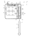
- FIG. 3 is an internal structural diagram showing an internal structural example of the vehicle-mounted device 10 as viewed from the Z-axis plus side.
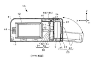
- FIG. 4 is an internal structural diagram showing an example of the internal structure of the vehicle-mounted device 10 as viewed from the positive side in the Y-axis direction.
- the vehicle-mounted device 10 is a key control device that unlocks/locks the housed electronic key 7 in response to an unlocking request/locking request from the user terminal 1500 .
- the vehicle-mounted device 10 is installed inside the vehicle 5 that is a sharing target, for example, inside the dashboard.
- the vehicle-mounted device 10 includes a main case portion 11 housing a mechanism for operating the electronic key 7, a cable 13 connected to the battery of the vehicle 5, a housing portion 20 detachably housing the electronic key 7 of the vehicle 5, have
- the housing portion 20 has a lid portion 23 pivotally supported on the main case portion 11 by a swing shaft 22 and a housing recess forming member 24 stretched inside the lid portion 23 .
- the housing portion 20 is configured such that the lid portion 23 opens when the opening/closing operation portion 15 connecting the main case portion 11 and the housing portion 20 is pushed and the engagement between the opening/closing operation portion 15 and the housing portion 20 is released. Become.
- the lid portion 23 has an opening 25 that is open even when the lid portion 23 is closed on the side surface in the positive direction of the Y axis.
- the electronic key 7 is housed so that the key ring 73 is exposed from the opening 25 to the outside. By exposing the key ring 73, it can be confirmed at a glance from the outside that the electronic key 7 is housed. Since the key ring 73 is exposed, the user can use the key ring 73 as a knob when removing the electronic key 7 from the housing portion 20 .
- the accommodation recess forming member 24 is a member that forms a recess into which the electronic key 7 is fitted.
- the shape of the recess formed by the accommodation recess forming member 24 is adapted to the external shape of the electronic key 7 .
- the electronic key 7 is fitted and housed in the housing recess forming member 2 with the push button facing in the positive direction of the X axis and the key ring 73 facing in the positive direction of the Y axis.
- the accommodating recess forming member 24 is molded with a cushioning material such as hard sponge, and attached to the inner side of the lid portion 23 by means of concave-convex fitting, double-sided tape, or the like.
- a partition wall 17 is provided between the housing portion 20 and the main case portion 11.
- the central portion of the partition wall 17 (the portion facing the housed electronic key 7) is wide open, and the interior space of the housing portion 20 and the main case portion are separated. It communicates with the internal space of the part 11 .
- the main case part 11 forms an internal space by screwing the back cover 12, and accommodates the control board 30, the first actuator 41, the second actuator 42, and the intermediate member 50.
- the built-in battery may be accommodated in the main case portion 11 .
- the control board 30 includes electronic components and various circuits such as a CPU (Central Processing Unit) 31, an IC memory 32, a first wireless communication module 33, a second wireless communication module 34, a power control circuit 35, and an interface IC 36.
- a CPU Central Processing Unit
- the first wireless communication module 33 is connected to a network 9 (specifically, a wireless communication network such as a mobile phone network and a wireless LAN), and communicates with a server system 1100 that manages reservations for vehicles 5 to be shared. .
- the second wireless communication module 34 realizes short-range wireless communication and establishes a communication connection with the user terminal 1500 within a communication range centering on the vehicle 5 .
- the power control circuit 35 controls power supply to the first actuator 41 and the second actuator 42 .
- the interface IC 36 realizes input/output of signals from the first wireless communication module 33 and the second wireless communication module 34 .
- the control board 30 integrally controls the operation of the vehicle-mounted device 10 by causing the CPU 31 to execute a program stored in the IC memory 32 .
- the first actuator 41 and the second actuator 42 are drive units that are operated by drive current control by the control board 30 to push the electronic key 7 accommodated in the accommodation portion 20 .
- the first actuator 41 and the second actuator 42 are implemented by push-type linear solenoids.
- the first actuator 41 and the second actuator 42 push out the movable projecting portion 43 (push rod of non-magnetic material connected to the movable iron core) by electromagnetic force as the driving current is applied.
- the first actuator 41 and the second actuator 42 return the movable protrusion 43 to the position before being pushed out by the force of the return spring 44 .
- the first actuator 41 is fixed to the main case portion 11 with the tip of the movable projecting portion 43 directed toward the unlocking button 71 of the electronic key 7 housed in the housing portion 20 .
- the second actuator 42 is fixed to the main case portion 11 with the tip of the movable protrusion 43 directed toward the lock button 72 of the electronic key 7 accommodated in the accommodation portion 20 .
- the intermediate member 50 is arranged between the electronic key 7 housed in the housing portion 20 and the first actuator 41 and the second actuator 42 .
- the intermediate member 50 is a plate-like member that transmits the pushing force of the movable protrusion 43 of these actuators to the push buttons (the unlock button 71 and the lock button 72) of the electronic key 7 as push button operation force.
- FIG. 5 is a view of an example of the first intermediate member 50 (50A) viewed from the minus side of the X axis (accommodating portion 20 side).
- FIG. 6 is a cross-sectional view along a plane parallel to the XY plane showing an example of the first intermediate member 50 (50A).
- FIG. 7 is a view of an example of the second intermediate member 50 (50B) viewed from the minus side of the X axis.
- FIG. 8 is a view of an example of the third intermediate member 50 (50C) viewed from the minus side of the X axis.
- FIG. 9 is a view of an example of the fourth intermediate member 50 (50D) viewed from the minus side of the X axis.
- the intermediate member 50 is an elastic plate-like member such as a metal plate or a synthetic resin plate, and has a peripheral portion 51 , a cantilever spring portion 52 and a gap portion 53 .
- a gap portion 53 By providing a gap portion 53 in the plate-like member by cutting, die-cutting, or the like, the edge portion 51 and the cantilever spring portion 52 are formed in one plate.
- the peripheral edge portion 51 is a portion that is fixed by being fitted into the grooves of the mounting portion 18 (18a, 18b) of the main case portion 11 .
- the first attachment portion 18a is provided on both the inner surfaces of the main case portion 11 on both the Y-axis plus direction side and the Y-axis minus direction side so as to have grooves along the Z-axis direction.
- the second mounting portion 18b is provided on the inner surface of the main case portion 11 on the Z-axis positive side so as to have a groove along the Y-axis direction.
- the peripheral edge portion 51 and the mounting portion 18 are fitted with such a strength that they do not come off or shift due to vibrations of the vehicle 5, but can be pulled out by pulling the intermediate member 50 by hand.
- the outer shape of the intermediate member 50 and the plate thickness of the edge portion 51 are common to all kinds of intermediate members 50, and any kind of intermediate member 50 can be attached to the attachment portion 18 (18a, 18b). .
- the intermediate member 50 is detachably attached to the main case portion 11 by the edge portion 51 .
- the work of assembling the intermediate member 50 to the main case portion 11 and the work of extracting it are easy.
- the cantilever spring portion 52 functions as a "cantilever-like plate spring" by being hit by the movable protrusion 43 as the first actuator 41 and the second actuator 42 are actuated. Specifically, as the cantilever spring portion 52, two of a first cantilever spring portion 52a pushed by the first actuator 41 and a second cantilever spring portion 52b pushed by the second actuator 42 are provided. .
- the cantilever spring portion 52 (52a, 52b) has a force point portion P1 with which the movable protrusion 43 of the actuator contacts one of both surfaces (first actuator 41 and second actuator 42 sides; X-axis plus side). There is On the other side of the two surfaces (accommodating section 20 side; X-axis negative side), there is an application point for applying force to the push button (unlock button 71, locking button 72) of the electronic key 7 accommodated in the accommodating section 20. There is P2. A buffer member 54 projects from the action point P2 toward the push button.
- the cushioning member 54 can be realized by silicon, butyl rubber, spring, or the like, for example.
- the illustrated example represents a member formed by molding silicone into the shape of a nipple.
- the material of the intermediate member 50 and the width and plate thickness of the fulcrum portion 55 of the cantilever spring portion 52 are selected and set so as to satisfy the following (1) and (2).
- the cantilever spring portion 52 is (a) in a state in which the push button of the housed electronic key 7 is not pushed down when the first actuator 41 and the second actuator 42 are not operating, and (b) When the first actuator 41 or the second actuator 42 is actuated, it bends enough to press the push button of the housed electronic key 7 .
- the vehicle-mounted device 10 can support various types of electronic keys 7 .
- a distance L1 is a distance from the fulcrum portion 55 of the cantilever spring portion 52 to the power point portion P1.
- a distance L2 is a distance from the fulcrum portion 55 to the action point portion P2.
- the vehicle-mounted device 10 of the present embodiment can have various degrees of design freedom according to the operating load, withstand load, and operating stroke of the push buttons (unlock button 71 and lock button 72) of the electronic key 7. .
- the first intermediate member 50 (50A )
- the electronic key 7 (7C) shown in FIG. 8 has the same relative positional relationship between the push buttons (unlock button 71 and lock button 72) as compared with the electronic key 7A shown in FIG. Or the operating stroke is large.
- the third intermediate member 50 (50C) corresponding to this electronic key 7 (7C) basically has the same design as the first intermediate member 50 (50A) in FIG. It has a typical small thickness portion 57 .
- the fulcrum portion 55 has a local narrow portion 58 .
- the cantilever spring portion 52 of the third intermediate member 50 (50C) bends more easily than the first intermediate member 50 (50A) of FIG. 5, and the load transmitted to the push button increases. Alternatively, the working stroke can be increased.
- the total length of the cantilever spring portion 52 may be set long and a narrow portion 58 may be provided.
- the types of the intermediate member 50 prepared for the vehicle-mounted device 10 are not limited to these four examples, and may include more types.
- the intermediate member 50 corresponding to the misplacement of the push buttons (the unlock button 71 and the lock button 72) in the electronic key 7 is obtained.
- a set of the intermediate member 50 corresponding to the type of the electronic key 7 and the accommodation recess forming member 24 is prepared for the vehicle-mounted device 10 .
- the intermediate member 50 can be easily inserted into and removed from the mounting portion 18, so that the user can easily and reliably reassemble the intermediate member 50.
- the receiving recess 24 can also be easily reconfigured.
- the vehicle-mounted device 10 includes an element that reduces the force in the process of transmitting the impact force of the movable protrusion 43 .
- This element is provided independently of the first actuator 41 and the second actuator 42 . For this reason, in addition to obtaining the above-described excellent assembling property and high degree of design freedom, a secondary effect of miniaturizing the vehicle-mounted device 10 can also be obtained.
- FIG. 10 is a diagram for explaining the effect of miniaturization of the vehicle-mounted device 10.
- FIG. A first actuator 41E and a second actuator 42E of the vehicle-mounted device 10E shown in FIG.
- the structural elements necessary for screwing the cushioning material 45 eg, the screw portion, the double nut for locking the cushioning material 45, etc.
- increase the overall length of the actuator As a result, the overall size of the vehicle-mounted device 10E is affected by this.
- the cantilever spring portion 52 of the intermediate member 50 and the cushioning member 54 replace the cushioning material 45 of FIG. 10(2).
- the first actuator 41 and the second actuator 42 do not have the cushioning material 45 and the structural elements necessary for screwing it. That is, a linear solenoid smaller than the first actuator 41E and the second actuator 42E can be used. Therefore, the overall size of the vehicle-mounted device 10 can be made smaller than the vehicle-mounted device 10E.
- Part 1 For example, a configuration in which the cushioning member 54 is detachably attached to the cantilever spring portion 52 may be added. Specifically, like the intermediate member 50 (50G) shown in FIG. 11, a mounting that can mount the buffer member 54 on the surface of the cantilever spring portion 52 on the negative direction side of the X axis (surface on the side of the accommodating portion 20) A plurality of candidate parts 56 may be prepared so that the cushioning member 54 can be selectively attached to and detached from any one of the candidate parts 56 .
- the attachment mechanism can be set as appropriate. As shown in FIG.
- a convex portion may be provided as the mounting candidate portion 56, which may be fitted into a concave portion on the side of the cushioning member 54, and may be attached/detached by inserting/removing it.
- an insertion hole may be provided as the mounting candidate portion 56, and the cushioning member 54 may be detachable by inserting and withdrawing the end portion of the cushioning member 54 into the insertion hole.
- a second cushioning member 54B may be added to the force point portion P1 on the X-axis plus side of the cantilever spring portion 52 .
- the cushioning member 54 may be omitted and the cushioning member may be provided only at the force point portion P1.
- the cantilever spring portion 52 is provided with a protrusion (for example, a protrusion having the same external shape as the buffer member 54 and integrally formed with the cantilever spring portion 52) instead of the omitted buffer member 54.
- the cushioning member 54H may be attached to the tip of a pedestal portion 59 projecting in the negative direction of the X axis (toward the accommodation portion 20) at the action point portion P2.
- the lid portion 23 of the housing portion 20 is opened and closed to store and take out the electronic key 7, but the lid portion 23 may be omitted.
- the vehicle-mounted device 10J of FIG. 13 does not have the lid portion 23, and instead has an insertion opening 19 through which the electronic key 7 can be inserted, at the end portion of the housing portion 20J in the positive Y-axis direction.
- the housing recess forming member 24J of the vehicle-mounted device 10J has a tubular structure having an insertion opening into which the electronic key 7 can be inserted from the Y-axis plus direction. The electronic key 7 is inserted into and removed from the recessed accommodation member 24J through the insertion opening 19 and the insertion opening of the recessed accommodation member 24J.
- An aspect of the present disclosure includes a housing portion housing an electronic key of a vehicle, an actuator that performs a push button operation with respect to the electronic key housed in the housing portion, the electronic key housed in the housing portion, and the actuator. and an intermediate member for transmitting the force of the push button operation to the push button of the electronic key, wherein the intermediate member includes a power point portion with which the movable protrusion of the actuator contacts, and the housing and a cushioning member provided at either one or both of an application point portion for applying force to the push button of the electronic key housed in the electronic key.
- the design elements of the pressing load applied to the push button are diverse, such as the material and size of the intermediate member, the relative positional relationship between the force point portion and the application point portion, and the size and material of the cushioning member. . Therefore, it is possible to increase the degree of freedom in designing the pressing load applied to the push button.
- the intermediate member has a cantilever spring portion, the force point portion is on one of both surfaces of the cantilever spring portion, and the action point portion is on the other of both surfaces of the cantilever spring portion. Yes, you can.
- the intermediate member may be a plate-shaped member having a marginal portion, the cantilever spring portion, and a gap portion between the marginal portion and the cantilever spring portion.
- the intermediate member includes a plurality of types of intermediate members having the same outer shape and having different shapes of the edge portion, the cantilever spring portion, and the space portion, and any of the plurality of types of intermediate members can be held.
- a mounting portion may be further provided.
- the plurality of types of intermediate members may have the force point portion at a common position and the action point portion at a common position.
- the plurality of types of intermediate members may have different distances from the fulcrum of the cantilever spring portion to the force point portion depending on the type.
- the plurality of types of intermediate members may have different distances from the fulcrum of the cantilever spring portion to the point of action depending on the type.
- the intermediate member may have a plurality of candidate sites for the point of action, and the candidate sites may be fitted with the cushioning member.
- the electronic key may have a key ring attachment portion to which a key ring can be attached, and the accommodation portion may accommodate the electronic key with the key ring attachment portion exposed.
Landscapes
- Lock And Its Accessories (AREA)
Abstract
車載器(10)は、車両の電子キー(7)を収容する収容部(20)と、収容された電子キー(7)に対して押釦動作をするアクチュエータ(41,42)と、収容された電子キー(7)とアクチュエータ(41,42)との間に配置され、押釦動作の力を電子キー(7)の押下釦(解錠釦(71)、施錠釦(72))に伝達する中間部材(50)と、を備える。中間部材(50)は、アクチュエータ(41,42)の可動突起部(43)が接触する力点部位(P1)、及び、収容された電子キー(7)の押下釦に力を作用させる作用点部位(P2)、のどちらか一方又は両方に設けられた緩衝部材(54)、を有する。
Description
本発明は、車両に搭載される車載器に関する。
自動車の利用形態として、複数人で1台又は複数台の車両をシェアする形態がある。カーシェアリングやレンタカーがそれに該当する。以降こうした利用形態を総括して「シェアリング」と呼ぶ。
シェアリングにおいては、シェアリング対象の車両を使用するための鍵の扱いが重要となる。例えば、特許文献1には、シェアリング等で利用可能な電子キーの収容装置が開示されている。具体的には、収容装置には、嵌め込みホルダに嵌め込まれた電子キーの押下釦を押圧動作する押圧機構が用意されている。押圧機構は、可動鉄心を直動させるソレノイドと、可動鉄心の先端に装着されて押下釦の上方へ延設された連結具と、連結具の先端から押下釦に向けて装着された軟質の弾性部材と、を有する。すなわち、押圧機構は、ソレノイドが作動すると弾性部材が押下釦に接近して押下釦を押圧する仕組みとなっている。
ソレノイドを用いる押圧機構では、押下釦の作動に必要な荷重を越えた衝撃力が押下釦に作用して、押下釦が破損したり寿命が低下することがある。特許文献1の技術では、連結具の先端に弾性部材が装着されている。当該弾性部材が衝撃力を吸収することで、押下釦の破損を防ぎ、寿命低下を抑制することが期待される。
しかしながら、電子キーには様々な種類があり、その種類によって、押下釦の数、配置、作動荷重、耐荷重、作動ストロークなどが異なる。
特許文献1の収容装置では、押下釦の配置違いに対応するには、組み立て工程において、弾性部材を押下釦の上方へ調整する作業が必要となる。具体的には、連結具とソレノイドとを取り付ける取付角度の調整や、連結具の長さの調整、等が必要となる。同じ電子キーを収容する場合であっても、摩耗や経年劣化に応じて弾性部材を交換する必要がある。特許文献1の収容装置では、弾性部材の交換作業においても上述した調整が必要となる。
ところが、特許文献1の構成においては、押下釦への押圧荷重は、連結具の長さによってほぼ決まってしまう。そのため、連結具の長さが固定である場合には、連結具の先端に装着する弾性部材の材質選択でしか押圧荷重を調整するしかなかった。つまり、押圧荷重を調整するための設計自由度が限定されていた。このために調整できる範囲も限定されていた。
本発明の目的の一例は、押下釦への押圧荷重の設計自由度を従来よりも高める技術を提供することである。
本発明の態様は、車両の電子キーを収容する収容部と、前記収容部に収容された前記電子キーに対して、押釦動作をするアクチュエータと、前記収容部に収容された前記電子キーと前記アクチュエータとの間に配置され、前記押釦動作の力を前記電子キーの押下釦に伝達する中間部材と、を備え、前記中間部材は、前記アクチュエータの可動突起部が接触する力点部位、及び、前記収容部に収容された前記電子キーの前記押下釦に力を作用させる作用点部位、のどちらか一方又は両方に設けられた緩衝部材、を有する、車載器である。
この態様によれば、押下釦への押圧荷重の設計要素は、多岐にわたる。よって、押下釦への押圧荷重の設計自由度を従来よりも高めることができる。
以下、好適な実施形態の例を説明するが、実施形態は以下の態様に限定されない。各図には右手系の直交三軸を示す。また、方向として、適宜、X軸プラス方向を前、X軸マイナス方向を後ろ、Y軸プラス方向を左、Y軸マイナス方向を右、Z軸プラス方向を上、Z軸マイナス方向を下、として説明する。
図1は、シェアリングシステムのシステム構成の例を示す図である。
シェアリングシステム3は、シェアリング対象である車両5の電子キー7を収容した車載器10と、ネットワーク9を介して車載器10と通信接続するサーバシステム1100と、ネットワーク9を介して車載器10と通信接続するユーザ端末1500と、を有する。電子キー7は、車両5に付属する純正のキーである。ユーザ端末1500は、シェアリング対象のユーザが使用する端末である。車両5には1つの車載器10が搭載される。実際のシェアリングシステム3の運用にあたっては、車両5及び車載器10のセットが1つ又は複数用意される。ユーザ端末1500は、例えば各ユーザの所有するスマートフォン等が用いられることとなる。
シェアリングシステム3は、シェアリング対象である車両5の電子キー7を収容した車載器10と、ネットワーク9を介して車載器10と通信接続するサーバシステム1100と、ネットワーク9を介して車載器10と通信接続するユーザ端末1500と、を有する。電子キー7は、車両5に付属する純正のキーである。ユーザ端末1500は、シェアリング対象のユーザが使用する端末である。車両5には1つの車載器10が搭載される。実際のシェアリングシステム3の運用にあたっては、車両5及び車載器10のセットが1つ又は複数用意される。ユーザ端末1500は、例えば各ユーザの所有するスマートフォン等が用いられることとなる。
電子キー7は、解錠釦71及び施錠釦72と、キーリング73と、キーリング73を装着するためのキーリング装着部74と、を有する。解錠釦71及び施錠釦72は、シェアリング対象の車両5が備える施錠機構を解錠/施錠する押下釦である。電子キー7は、解錠釦71が押釦操作されると所定の解錠信号を発信し、施錠釦72が押釦操作されると所定の施錠信号を発信する。電子キー7は物理キーを内蔵或いは露出した構成であってもよい。また、電子キー7は、車両5に当初から付属するオリジナルの純正キーであるが、車両メーカが指定する所定手続を経て正規に複製されたキーであってもよい。キーリング73は、紐でもよいし、省略してもよい。
ネットワーク9は、データ通信が可能な通信路を意味する。すなわち、ネットワーク9とは、直接接続のための専用線(専用ケーブル)やイーサネット(登録商標)等によるLAN(Local Area Network)の他、電話通信網やケーブル網、インターネット等の通信網を含む意味であり、また、通信方法については有線/無線を問わない。
サーバシステム1100は、シェアリングシステム3のユーザ登録と、予約管理と、ユーザ端末1500や車載器10への予約情報の提供と、を行う。具体的には、サーバシステム1100は、管理プログラム501を記憶し、これを実行することによって、(1)ユーザ登録機能、(2)車両5別の予約設定機能、(3)予約情報700(例えば、固有の予約ID、予約車両ID、予約期間、パスワードなどを含む。)の生成機能、(4)予約情報700の写し(予約情報700t)をユーザ端末1500へ提供する機能、(5)予約情報700の写し(予約情報700c)を車載器10へ提供する機能、を実装する。
ユーザ端末1500は、車両5をシェアしたいユーザが使用するネットワーク9に接続可能なコンピュータシステムである。ユーザ端末1500は、例えばスマートフォン、タブレット型コンピュータ、ノートパソコン、ウェアラブルコンピュータ等により実現される。
ユーザ端末1500は、アプリケーションプログラムを記憶し、実行することができる。アプリケーションプログラムとしては、端末プログラム502を記憶している。端末プログラム502は、(1)サーバシステム1100にアクセスするための機能と、(2)ユーザによるユーザ端末1500への解錠操作に応じて車載器10へ所定の解錠要求を行い、予約情報700tを提供して車載器10に解錠させる機能と、(3)ユーザによるユーザ端末1500への施錠操作に応じて車載器10と通信接続して所定の施錠要求を行い、予約情報700tを提供して車載器10に施錠させる機能と、を実現させる。
図2は、車載器10の外観例を示す上面図である。
図3は、車載器10の内部構造例を示すZ軸プラス側から見た内部構造図である。
図4は、車載器10の内部構造例を示すY軸方向プラス側から見た内部構造図である。
図3は、車載器10の内部構造例を示すZ軸プラス側から見た内部構造図である。
図4は、車載器10の内部構造例を示すY軸方向プラス側から見た内部構造図である。
車載器10は、ユーザ端末1500からの解錠要求/施錠要求に応じて、収容された電子キー7に対して解錠動作/施錠動作をする鍵制御装置である。車載器10は、シェアリング対象である車両5の車内、例えばダッシュボード内などに取り付けられる。
車載器10は、電子キー7を操作する機構を収容する主ケース部11と、車両5のバッテリーに接続されるケーブル13と、車両5の電子キー7を脱着自在に収容する収容部20と、を有する。
収容部20は、主ケース部11に揺動軸22で枢支された蓋部23と、蓋部23の内側に張設された収容凹部形成材24と、を有する。収容部20は、主ケース部11と収容部20とを連結する開閉操作部15が押されて、開閉操作部15と収容部20との係合が解除されると蓋部23が開くようになる。
蓋部23は、Y軸プラス方向の側面に蓋部23が閉じた状態でも開いている開口部25を有する。電子キー7はキーリング73が開口部25から外部に露出するように収容される。キーリング73が露出することで、電子キー7が収容されていることを外部から一瞥で確認できる。キーリング73が露出していることで、ユーザは電子キー7を収容部20から取り外す際に、キーリング73を摘まみとして利用できる。
収容凹部形成材24は、電子キー7を嵌め込む凹部を形成する部材である。収容凹部形成材24が形作る凹部形状は、電子キー7の外形に適合している。電子キー7は、押下釦をX軸プラス方向に向け、且つ、キーリング73をY軸プラス方向に向けた姿勢で収容凹部形成材2に嵌め込まれて収容される。収容凹部形成材24は、例えば硬質スポンジなどの緩衝材で成型され、蓋部23の内側に、凹凸嵌合や両面テープなどにより取り付けられている。
収容部20と主ケース部11との間には隔壁17があるが、隔壁17の中央部(収容された電子キー7と対向する部分)が大きく開口し、収容部20の内部空間と主ケース部11の内部空間とが通じている。
主ケース部11は、裏蓋12をネジ止めすることで内部空間を形成し、制御基板30と、第1アクチュエータ41と、第2アクチュエータ42と、中間部材50と、を収容する。車載器10が内蔵バッテリーを備える構成では、主ケース部11内に内蔵バッテリーを収容してもよい。
制御基板30は、CPU(Central Processing Unit)31、ICメモリ32、第1無線通信モジュール33、第2無線通信モジュール34、電力制御回路35、インターフェースIC36、などの電子部品や各種回路を備える。
第1無線通信モジュール33は、ネットワーク9(具体的には、携帯電話網、無線LANといった無線通信網)に接続し、シェアリング対象である車両5の予約を管理するサーバシステム1100と通信接続する。
第2無線通信モジュール34は、近距離無線通信を実現し、車両5を中心とした通信範囲内に入ったユーザ端末1500と通信接続する。
第2無線通信モジュール34は、近距離無線通信を実現し、車両5を中心とした通信範囲内に入ったユーザ端末1500と通信接続する。
電力制御回路35は、第1アクチュエータ41及び第2アクチュエータ42への電力供給を制御する。
インターフェースIC36は、第1無線通信モジュール33及び第2無線通信モジュール34からの信号の入出力を実現する。
制御基板30は、ICメモリ32に記憶されているプログラムをCPU31で実行することで車載器10の動作を統合的に制御する。
第1アクチュエータ41及び第2アクチュエータ42は、制御基板30による駆動電流制御によって作動して、収容部20に収容された電子キー7に対して押釦動作をする駆動部である。具体的には、第1アクチュエータ41及び第2アクチュエータ42は、プッシュ式のリニアソレノイドで実現される。第1アクチュエータ41及び第2アクチュエータ42は、駆動電流の通電にともなって電磁力で可動突起部43(可動鉄心に連結された非磁性材のプッシュロッド)を押し出す。第1アクチュエータ41及び第2アクチュエータ42は、駆動電流の停止にともなってリターンスプリング44の付勢により可動突起部43を押し出し前の位置に復帰させる。
可動突起部43の先端には付属物は装着されていない。第1アクチュエータ41は、可動突起部43の先端を収容部20に収容された電子キー7の解錠釦71に向けた姿勢で主ケース部11に固定されている。第2アクチュエータ42は、可動突起部43の先端を収容部20に収容された電子キー7の施錠釦72に向けた姿勢で主ケース部11に固定されている。
中間部材50は、収容部20に収容された電子キー7と、第1アクチュエータ41及び第2アクチュエータ42との間に配置される。中間部材50は、これらアクチュエータの可動突起部43の押し出しを押釦動作の力として電子キー7の押下釦(解錠釦71,施錠釦72)に伝達する板状部材である。
車載器10には、装着可能な複数種類の中間部材50が用意されている。
図5は、第1の中間部材50(50A)の例を示すX軸マイナス側(収容部20側)から見た図である。
図6は、第1の中間部材50(50A)の例を示すXY面と平行な面での断面図である。
図7は、第2の中間部材50(50B)の例を示すX軸マイナス側から見た図である。
図8は、第3の中間部材50(50C)の例を示すX軸マイナス側から見た図である。
図9は、第4の中間部材50(50D)の例を示すX軸マイナス側から見た図である。
図5は、第1の中間部材50(50A)の例を示すX軸マイナス側(収容部20側)から見た図である。
図6は、第1の中間部材50(50A)の例を示すXY面と平行な面での断面図である。
図7は、第2の中間部材50(50B)の例を示すX軸マイナス側から見た図である。
図8は、第3の中間部材50(50C)の例を示すX軸マイナス側から見た図である。
図9は、第4の中間部材50(50D)の例を示すX軸マイナス側から見た図である。
中間部材50は、金属板又は合成樹脂板などの弾性を有する板状部材であって、辺縁部51と、片持ちバネ部52と、空隙部53と、を有する。切削又は型抜き等で板状部材に空隙部53を設けることで、辺縁部51と片持ちバネ部52とが1枚の板に形成されている。
辺縁部51は、主ケース部11の取付部18(18a,18b)の溝に嵌め込まれて固定される部位である。第1の取付部18aは、主ケース部11の内面であるY軸プラス方向側及びY軸マイナス方向側の両方の内面に、Z軸方向に沿った溝を有するように設けられている。第2の取付部18bは、主ケース部11のZ軸プラス側の内面にY軸方向に沿った溝を有するように設けられている。
辺縁部51と取付部18とは、車両5の振動等では抜けたりズレたりしないが、人の手で中間部材50を引っ張れば引き抜き可能な強度で嵌まっている。中間部材50の外形及び辺縁部51の板厚は、全ての種類の中間部材50で共通とされ、どの種類の中間部材50の何れもが取付部18(18a、18b)に取り付け可能である。
中間部材50は辺縁部51によって主ケース部11に対して、抜き差し可能に取り付けられる。中間部材50を主ケース部11に組み付ける作業や抜き出す作業は簡単である。
片持ちバネ部52は、第1アクチュエータ41及び第2アクチュエータ42の作動にともない可動突起部43の衝突を受けることで「片持ち梁状の板バネ」として機能する。具体的には、片持ちバネ部52として、第1アクチュエータ41により押される第1片持ちバネ部52aと、第2アクチュエータ42により押される第2片持ちバネ部52bとの2つが設けられている。
片持ちバネ部52(52a,52b)は、両面のうちの一方(第1アクチュエータ41及び第2アクチュエータ42の側;X軸プラス側)には、アクチュエータの可動突起部43が接触する力点部位P1がある。両面のうちの他方(収容部20の側;X軸マイナス側)には収容部20に収容された電子キー7の押下釦(解錠釦71,施錠釦72)に力を作用させる作用点部位P2がある。作用点部位P2には、押下釦に向けて緩衝部材54が突設されている。
第1アクチュエータ41や第2アクチュエータ42が作動した際に、可動突起部43が中間部材50に衝突して生み出す衝撃力が、中間部材50によって電子キー7の押下釦(解錠釦71,施錠釦72)に伝達される。しかし、その伝達される力は緩衝部材54によって減少させられる。緩衝部材54は、例えば、シリコンや、ブチルゴム、スプリングなどにより実現できる。図示の例は、シリコンをニップル状に成形した部材を表している。
中間部材50の材質と、片持ちバネ部52の支点部位55の幅や板厚は、次の(1)及び(2)を充足するように選択・設定されている。(1)第1アクチュエータ41及び第2アクチュエータ42が作動した際に可動突起部43から受ける荷重により撓むこと。(2)緩衝部材54の先端が収容部20に収容された電子キー7の押下釦(解錠釦71、施錠釦72)に接触し、更に撓み量が押下釦を作動させるのに十分なストロークを得ること。
言い換えると、片持ちバネ部52は、(a)第1アクチュエータ41及び第2アクチュエータ42が作動していない状態では、収容された電子キー7の押下釦を押し下げない状態にあり、且つ(b)第1アクチュエータ41や第2アクチュエータ42が作動すると、収容された電子キー7の押下釦を押圧動作するのに十分なだけ撓む。
第1アクチュエータ41や第2アクチュエータ42が作動して中間部材50に衝撃力が作用しても、片持ちバネ部52の撓みと緩衝部材54により、衝撃力の押下釦(解錠釦71、施錠釦72)への伝達は適度に低減され、押下釦は衝撃力から保護される。
中間部材50と緩衝部材54とを採用し、これらの諸元を適切に設定することで、車載器10は、様々な種類の電子キー7に対応できるようになる。
具体的には、第1アクチュエータ41や第2アクチュエータ42が中間部材50を押す荷重が同じであっても、距離L1と距離L2とによって、最終的に電子キー7の押下釦(解錠釦71、施錠釦72)に伝達される力が変わる。距離L1は、片持ちバネ部52の支点部位55から力点部位P1までの距離である。距離L2は、支点部位55から作用点部位P2まで距離である。
よって、本実施形態の車載器10は、電子キー7の押下釦(解錠釦71、施錠釦72)の作動荷重や耐荷重、作動ストロークに応じた、様々な設計自由度を持つことができる。例えば、第1アクチュエータ41や第2アクチュエータ42が中間部材50を押す荷重よりも、押下釦に伝達される荷重を小さくしたい場合には、図5、図6に示す第1の中間部材50(50A)のように「支点部位55から力点部位P1までの距離L1」<「支点部位55から作用点部位P2までの距離L2」とすることで対応できる。
例えば、第1アクチュエータ41や第2アクチュエータ42が中間部材50を押す荷重と、押下釦に伝達される荷重とをほぼ同じにしたい場合には、図7に示すように、「支点部位55から力点部位P1までの距離L1」と「支点部位55から作用点部位P2までの距離L2」とを同じ又はほぼ同じとすることで対応できる。
例えば、図8に示す電子キー7(7C)は、図5の電子キー7Aと比較すると、押釦(解錠釦71、施錠釦72)の相対位置関係は同じだが、押下釦の作動荷重が大きい或いは作動ストロークが大きい。この電子キー7(7C)に対応する第3の中間部材50(50C)は、基本的には図5の第1の中間部材50(50A)と同様のデザインを有するが、支点部位55に局所的な小厚部57を有する。或いは、支点部位55に局所的な狭幅部58を有する。これにより、第3の中間部材50(50C)は、図5の第1の中間部材50(50A)よりも片持ちバネ部52がより撓み易くなり、押下釦に伝達される荷重が大きくなる、或いは、作動ストロークを大きくすることができる。
別の仕様として、図9に示す第4の中間部材50(50D)のように、片持ちバネ部52の全長を長く設定して、更に狭幅部58を設けるとしてもよい。
車載器10に用意されている中間部材50の種類は、これら4種の例に限らず、もっと多くの種類があっても良い。例えば、辺縁部51と、片持ちバネ部52と、力点部位P1の位置と、は同じであるが、作用点部位P2の位置違いとなる種類の中間部材50を用意することもできる。作用点部位P2を適切に設定することで、電子キー7における押下釦(解錠釦71、施錠釦72)の配置違いに対応する中間部材50となる。
車載器10には、電子キー7の種類に対応する中間部材50と収容凹部形成材24とのセットが用意される。前述のように、中間部材50は取付部18へ簡単に抜き差しできるので、ユーザは簡単且つ確実に中間部材50を組み換えることができる。収容凹部形成材24もまた簡単に組み換えできる。
車載器10は、可動突起部43の衝撃力を伝達する過程でその力を低減させる要素を備える。当該要素は、第1アクチュエータ41や第2アクチュエータ42から独立して設けられている。このため、上述のような優れた組み立て性と高い設計自由度が得られる他に、車載器10を小型化する副次的効果も得られる。
図10は、車載器10の小型化の効果について説明するための図である。
図10(2)に示す車載器10Eの第1アクチュエータ41E、第2アクチュエータ42Eは、可動突起部43の先端部にネジ止め式の緩衝材45を有している。こうした形式のリニアソレノイドを採用した場合、緩衝材45をネジ止めするために必要な構造要素(例えば、ネジ部、緩衝材45の緩み止めのダブルナット、など)がアクチュエータの全長を大きくする。ひいては車載器10Eの全体サイズはこの影響を受ける。
図10(2)に示す車載器10Eの第1アクチュエータ41E、第2アクチュエータ42Eは、可動突起部43の先端部にネジ止め式の緩衝材45を有している。こうした形式のリニアソレノイドを採用した場合、緩衝材45をネジ止めするために必要な構造要素(例えば、ネジ部、緩衝材45の緩み止めのダブルナット、など)がアクチュエータの全長を大きくする。ひいては車載器10Eの全体サイズはこの影響を受ける。
しかし、図10(1)に示す本実施態様の車載器10では、中間部材50の片持ちバネ部52と緩衝部材54とが図10(2)の緩衝材45に代替する。第1アクチュエータ41及び第2アクチュエータ42は、緩衝材45とこれをネジ止めするために必要な構造要素を備えない。つまり、第1アクチュエータ41Eや第2アクチュエータ42Eよりも小型のリニアソレノイドを採用することができる。よって、車載器10の全体サイズを、車載器10Eに比べて小さくすることができる。
<他の実施の形態>
以上、実施形態の一例について説明したが、本開示の態様は上記形態に限定されるものではなく適宜構成要素の追加・省略・変更を施すことができる。
以上、実施形態の一例について説明したが、本開示の態様は上記形態に限定されるものではなく適宜構成要素の追加・省略・変更を施すことができる。
(その1)
例えば、片持ちバネ部52に緩衝部材54を着脱自在に装着する構成を加えても良い。具体的には、図11に示す中間部材50(50G)のように、片持ちバネ部52のX軸マイナス方向側の面(収容部20側の面)に、緩衝部材54を装着可能な装着候補部位56を複数箇所用意し、緩衝部材54を何れかの装着候補部位56へ選択的に着脱できるようにしてもよい。装着の仕組みは適宜設定可能である。図11のように、装着候補部位56として凸部を設け、これを緩衝部材54側の凹部と嵌合させる構造とし、抜き差しすることで着脱自在としてもよい。或いは、装着候補部位56として挿通孔を設け、緩衝部材54の端部を挿通孔に抜き差しすることで着脱自在としてもよい。
例えば、片持ちバネ部52に緩衝部材54を着脱自在に装着する構成を加えても良い。具体的には、図11に示す中間部材50(50G)のように、片持ちバネ部52のX軸マイナス方向側の面(収容部20側の面)に、緩衝部材54を装着可能な装着候補部位56を複数箇所用意し、緩衝部材54を何れかの装着候補部位56へ選択的に着脱できるようにしてもよい。装着の仕組みは適宜設定可能である。図11のように、装着候補部位56として凸部を設け、これを緩衝部材54側の凹部と嵌合させる構造とし、抜き差しすることで着脱自在としてもよい。或いは、装着候補部位56として挿通孔を設け、緩衝部材54の端部を挿通孔に抜き差しすることで着脱自在としてもよい。
(その2)
図12に示すように、片持ちバネ部52のX軸プラス側面の力点部位P1に、第2緩衝部材54Bを追加してもよい。第2緩衝部材54Bを設ける代わりに、緩衝部材54を省略して力点部位P1のみに緩衝部材が備わった構成としても良い。この場合、片持ちバネ部52に、省略された緩衝部材54に代わる突起部(例えば、外形が緩衝部材54と同様で片持ちバネ部52と一体成形された突起部)を設ける。また、緩衝部材54Hを、作用点部位P2にX軸マイナス方向(収容部20側)へ突設された台座部59の先端に取り付ける構成としてもよい。
図12に示すように、片持ちバネ部52のX軸プラス側面の力点部位P1に、第2緩衝部材54Bを追加してもよい。第2緩衝部材54Bを設ける代わりに、緩衝部材54を省略して力点部位P1のみに緩衝部材が備わった構成としても良い。この場合、片持ちバネ部52に、省略された緩衝部材54に代わる突起部(例えば、外形が緩衝部材54と同様で片持ちバネ部52と一体成形された突起部)を設ける。また、緩衝部材54Hを、作用点部位P2にX軸マイナス方向(収容部20側)へ突設された台座部59の先端に取り付ける構成としてもよい。
(その3)
上記実施形態では、収容部20の蓋部23を開閉して電子キー7を収容したり取り出したりする構成としたが、蓋部23を省略してもよい。具体的には、図13の車載器10Jは、蓋部23が省略され、代わりに収容部20JのY軸プラス方向端部に電子キー7を挿通可能な挿通口19を有する。車載器10Jの収容凹部形成材24Jは、Y軸プラス方向から電子キー7を挿入可能な挿入口を有する筒状構造を有する。電子キー7は、挿通口19と収容凹部形成材24Jの挿入口を通じて、収容凹部形成材24Jへ挿抜される。
上記実施形態では、収容部20の蓋部23を開閉して電子キー7を収容したり取り出したりする構成としたが、蓋部23を省略してもよい。具体的には、図13の車載器10Jは、蓋部23が省略され、代わりに収容部20JのY軸プラス方向端部に電子キー7を挿通可能な挿通口19を有する。車載器10Jの収容凹部形成材24Jは、Y軸プラス方向から電子キー7を挿入可能な挿入口を有する筒状構造を有する。電子キー7は、挿通口19と収容凹部形成材24Jの挿入口を通じて、収容凹部形成材24Jへ挿抜される。
〔概括〕
上述した実施形態による本明細書の開示は、次のように概括することができる。
上述した実施形態による本明細書の開示は、次のように概括することができる。
本開示態様は、車両の電子キーを収容する収容部と、前記収容部に収容された前記電子キーに対して、押釦動作をするアクチュエータと、前記収容部に収容された前記電子キーと前記アクチュエータとの間に配置され、前記押釦動作の力を前記電子キーの押下釦に伝達する中間部材と、を備え、前記中間部材は、前記アクチュエータの可動突起部が接触する力点部位、及び、前記収容部に収容された前記電子キーの前記押下釦に力を作用させる作用点部位、のどちらか一方又は両方に設けられた緩衝部材、を有する、車載器である。
この態様によれば、押下釦への押圧荷重の設計要素は、中間部材の材料、寸法、力点部位と作用点部位との相対位置関係、緩衝部材の寸法や材料、と言った具合に多岐にわたる。よって、押下釦への押圧荷重の設計自由度を従来よりも高めることができる。
前記中間部材は、片持ちバネ部を有し、前記力点部位は、前記片持ちバネ部の両面のうちの一方にあり、前記作用点部位は、前記片持ちバネ部の両面のうちの他方にある、としてもよい。
前記中間部材は、辺縁部と、前記片持ちバネ部と、前記辺縁部と前記片持ちバネ部との間の空隙部と、を有する板状部材である、としてもよい。
前記中間部材には、外形が同じであり、前記辺縁部、前記片持ちバネ部、及び前記空隙部の形状が異なる複数種類の中間部材があり、前記複数種類の中間部材の何れも保持可能な取付部、を更に備える、としてもよい。
前記複数種類の中間部材は、前記力点部位が共通の位置にあり、且つ、前記作用点部位が共通の位置にある、としてもよい。
前記複数種類の中間部材は、前記片持ちバネ部の支点から前記力点部位までの距離が種類に応じて異なる、としてもよい。
前記複数種類の中間部材は、前記片持ちバネ部の支点から前記作用点部位までの距離が種類に応じて異なる、としてもよい。
前記中間部材は、前記作用点部位の候補部位を複数有し、前記候補部位は、前記緩衝部材を装着可能である、としてもよい。
前記電子キーは、キーリングを装着可能なキーリング装着部を有し、前記収容部は、前記キーリング装着部を露出させた状態で前記電子キーを収容する、としてもよい。
7(7A,7B,…)…電子キー
10,10E,10J…車載器
11…主ケース部
12…裏蓋
13…ケーブル
15…開閉操作部
17…隔壁
18(18a,18b)…取付部
19…挿通口
20,20J…収容部
22…揺動軸
23…蓋部
24,24J…収容凹部形成材
25…開口部
30…制御基板
41…第1アクチュエータ
42…第2アクチュエータ
43…可動突起部
44…リターンスプリング
45…緩衝材
50(50A,50B,…)…中間部材
51…辺縁部
52(52a,52b)…片持ちバネ部
53…空隙部
54…緩衝部材
54B…第2緩衝部材
55…支点部位
56…装着候補部位
73…キーリング
74…キーリング装着部
P1…力点部位
P2…作用点部位
10,10E,10J…車載器
11…主ケース部
12…裏蓋
13…ケーブル
15…開閉操作部
17…隔壁
18(18a,18b)…取付部
19…挿通口
20,20J…収容部
22…揺動軸
23…蓋部
24,24J…収容凹部形成材
25…開口部
30…制御基板
41…第1アクチュエータ
42…第2アクチュエータ
43…可動突起部
44…リターンスプリング
45…緩衝材
50(50A,50B,…)…中間部材
51…辺縁部
52(52a,52b)…片持ちバネ部
53…空隙部
54…緩衝部材
54B…第2緩衝部材
55…支点部位
56…装着候補部位
73…キーリング
74…キーリング装着部
P1…力点部位
P2…作用点部位
Claims (9)
- 車両の電子キーを収容する収容部と、
前記収容部に収容された前記電子キーに対して、押釦動作をするアクチュエータと、
前記収容部に収容された前記電子キーと前記アクチュエータとの間に配置され、前記押釦動作の力を前記電子キーの押下釦に伝達する中間部材と、
を備え、
前記中間部材は、
前記アクチュエータの可動突起部が接触する力点部位、及び、前記収容部に収容された前記電子キーの前記押下釦に力を作用させる作用点部位、のどちらか一方又は両方に設けられた緩衝部材、
を有する、
車載器。 - 前記中間部材は、片持ちバネ部を有し、
前記力点部位は、前記片持ちバネ部の両面のうちの一方にあり、
前記作用点部位は、前記片持ちバネ部の両面のうちの他方にある、
請求項1に記載の車載器。 - 前記中間部材は、
辺縁部と、
前記片持ちバネ部と、
前記辺縁部と前記片持ちバネ部との間の空隙部と、
を有する板状部材である、
請求項2に記載の車載器。 - 前記中間部材には、外形が同じであり、前記辺縁部、前記片持ちバネ部、及び前記空隙部の形状が異なる複数種類の中間部材があり、
前記複数種類の中間部材の何れも保持可能な取付部、
を更に備える請求項3に記載の車載器。 - 前記複数種類の中間部材は、前記力点部位が共通の位置にあり、且つ、前記作用点部位が共通の位置にある、
請求項4に記載の車載器。 - 前記複数種類の中間部材は、前記片持ちバネ部の支点から前記力点部位までの距離が種類に応じて異なる、
請求項4又は5に記載の車載器。 - 前記複数種類の中間部材は、前記片持ちバネ部の支点から前記作用点部位までの距離が種類に応じて異なる、
請求項4~6の何れか一項に記載の車載器。 - 前記中間部材は、前記作用点部位の候補部位を複数有し、
前記候補部位は、前記緩衝部材を装着可能である、
請求項1~7の何れか一項に記載の車載器。 - 前記電子キーは、キーリングを装着可能なキーリング装着部を有し、
前記収容部は、前記キーリング装着部を露出させた状態で前記電子キーを収容する、
請求項1~8の何れか一項に記載の車載器。
Applications Claiming Priority (2)
| Application Number | Priority Date | Filing Date | Title |
|---|---|---|---|
| JP2021-009489 | 2021-01-25 | ||
| JP2021009489A JP7791652B2 (ja) | 2021-01-25 | 2021-01-25 | 車載器 |
Publications (1)
| Publication Number | Publication Date |
|---|---|
| WO2022158016A1 true WO2022158016A1 (ja) | 2022-07-28 |
Family
ID=82549648
Family Applications (1)
| Application Number | Title | Priority Date | Filing Date |
|---|---|---|---|
| PCT/JP2021/030545 Ceased WO2022158016A1 (ja) | 2021-01-25 | 2021-08-20 | 車載器 |
Country Status (2)
| Country | Link |
|---|---|
| JP (1) | JP7791652B2 (ja) |
| WO (1) | WO2022158016A1 (ja) |
Cited By (1)
| Publication number | Priority date | Publication date | Assignee | Title |
|---|---|---|---|---|
| WO2024049345A1 (en) * | 2022-08-29 | 2024-03-07 | Trusty Cars Ltd. | A remote-control actuator |
Families Citing this family (1)
| Publication number | Priority date | Publication date | Assignee | Title |
|---|---|---|---|---|
| JP2024103379A (ja) * | 2023-01-20 | 2024-08-01 | 株式会社ビットキー | 釦操作判定装置、釦操作判定プログラム、釦操作判定方法、及び操作装置 |
Citations (4)
| Publication number | Priority date | Publication date | Assignee | Title |
|---|---|---|---|---|
| JP4087655B2 (ja) * | 2002-07-23 | 2008-05-21 | 株式会社東海理化電機製作所 | メカキーを収容した携帯機 |
| JP5179630B2 (ja) * | 2011-08-05 | 2013-04-10 | 株式会社東海理化電機製作所 | 車両用携帯機 |
| JP2019512630A (ja) * | 2016-04-01 | 2019-05-16 | ワイ シェア エス アール エルY.Share S.r.l. | キーを保持及び共有するための安全デバイス |
| JP6710832B1 (ja) * | 2019-12-17 | 2020-06-17 | 株式会社データ・テック | 車両の電子キーの収納装置、携帯情報端末、電子キーの共用方法、コンピュータプログラム |
-
2021
- 2021-01-25 JP JP2021009489A patent/JP7791652B2/ja active Active
- 2021-08-20 WO PCT/JP2021/030545 patent/WO2022158016A1/ja not_active Ceased
Patent Citations (4)
| Publication number | Priority date | Publication date | Assignee | Title |
|---|---|---|---|---|
| JP4087655B2 (ja) * | 2002-07-23 | 2008-05-21 | 株式会社東海理化電機製作所 | メカキーを収容した携帯機 |
| JP5179630B2 (ja) * | 2011-08-05 | 2013-04-10 | 株式会社東海理化電機製作所 | 車両用携帯機 |
| JP2019512630A (ja) * | 2016-04-01 | 2019-05-16 | ワイ シェア エス アール エルY.Share S.r.l. | キーを保持及び共有するための安全デバイス |
| JP6710832B1 (ja) * | 2019-12-17 | 2020-06-17 | 株式会社データ・テック | 車両の電子キーの収納装置、携帯情報端末、電子キーの共用方法、コンピュータプログラム |
Cited By (1)
| Publication number | Priority date | Publication date | Assignee | Title |
|---|---|---|---|---|
| WO2024049345A1 (en) * | 2022-08-29 | 2024-03-07 | Trusty Cars Ltd. | A remote-control actuator |
Also Published As
| Publication number | Publication date |
|---|---|
| JP2022113329A (ja) | 2022-08-04 |
| JP7791652B2 (ja) | 2025-12-24 |
Similar Documents
| Publication | Publication Date | Title |
|---|---|---|
| JP7339974B2 (ja) | 車載器 | |
| US8542482B2 (en) | Key assembly and electronic device using key assembly | |
| JP5545673B2 (ja) | パワーウインドウスイッチ | |
| JP2022113329A (ja) | 車載器 | |
| KR20040103457A (ko) | 소형화된 구조를 갖는 전자식 키 시스템 및 기계식 키시스템을 갖춘 휴대 장치 | |
| KR102190894B1 (ko) | 차키 버튼 누름장치를 활용한 차량 관리 시스템 | |
| US8378244B2 (en) | Portable electronic device | |
| TW202237462A (zh) | 用於鎖定電池組的鎖定裝置 | |
| CN114270003B (zh) | 收纳盒以及车辆租赁系统 | |
| JP2004297068A (ja) | 携帯端末機のバッテリカバーロッキング装置 | |
| JP2021095746A (ja) | 車両の電子キーの収納装置、携帯情報端末、電子キーの共用方法、コンピュータプログラム | |
| US12116809B2 (en) | Vehicular door handle device | |
| JP2026015404A (ja) | 入力デバイス及び操作スティックのトップ部材 | |
| JP2011042989A (ja) | キーの電子部品モジュール保持構造 | |
| JP5206534B2 (ja) | 電子キー | |
| WO2022249825A1 (ja) | 車載器 | |
| JP2024082364A (ja) | ロック装置 | |
| US20240247707A1 (en) | Electronic key operation device | |
| JP2020204233A (ja) | 車両用ドアハンドル装置、及び車両用ドアハンドル装置の電子回路装置の固定方法 | |
| JP4972717B2 (ja) | 機器筐体 | |
| WO2022249824A1 (ja) | 車載器取付具 | |
| US12559972B2 (en) | Vehicle-mounted apparatus | |
| JP7732336B2 (ja) | 車両用ドアハンドル装置 | |
| JP2014203055A (ja) | 光トランシーバ | |
| US20250020193A1 (en) | Electronic key operating device |
Legal Events
| Date | Code | Title | Description |
|---|---|---|---|
| 121 | Ep: the epo has been informed by wipo that ep was designated in this application |
Ref document number: 21921121 Country of ref document: EP Kind code of ref document: A1 |
|
| NENP | Non-entry into the national phase |
Ref country code: DE |
|
| 122 | Ep: pct application non-entry in european phase |
Ref document number: 21921121 Country of ref document: EP Kind code of ref document: A1 |