WO2022157961A1 - Uボルト及び施工方法 - Google Patents
Uボルト及び施工方法 Download PDFInfo
- Publication number
- WO2022157961A1 WO2022157961A1 PCT/JP2021/002390 JP2021002390W WO2022157961A1 WO 2022157961 A1 WO2022157961 A1 WO 2022157961A1 JP 2021002390 W JP2021002390 W JP 2021002390W WO 2022157961 A1 WO2022157961 A1 WO 2022157961A1
- Authority
- WO
- WIPO (PCT)
- Prior art keywords
- bolt
- support surface
- pair
- fastened
- supported
- Prior art date
- Legal status (The legal status is an assumption and is not a legal conclusion. Google has not performed a legal analysis and makes no representation as to the accuracy of the status listed.)
- Ceased
Links
Images






Classifications
-
- F—MECHANICAL ENGINEERING; LIGHTING; HEATING; WEAPONS; BLASTING
- F16—ENGINEERING ELEMENTS AND UNITS; GENERAL MEASURES FOR PRODUCING AND MAINTAINING EFFECTIVE FUNCTIONING OF MACHINES OR INSTALLATIONS; THERMAL INSULATION IN GENERAL
- F16B—DEVICES FOR FASTENING OR SECURING CONSTRUCTIONAL ELEMENTS OR MACHINE PARTS TOGETHER, e.g. NAILS, BOLTS, CIRCLIPS, CLAMPS, CLIPS OR WEDGES; JOINTS OR JOINTING
- F16B31/00—Screwed connections specially modified in view of tensile load; Break-bolts
- F16B31/02—Screwed connections specially modified in view of tensile load; Break-bolts for indicating the attainment of a particular tensile load or limiting tensile load
-
- F—MECHANICAL ENGINEERING; LIGHTING; HEATING; WEAPONS; BLASTING
- F16—ENGINEERING ELEMENTS AND UNITS; GENERAL MEASURES FOR PRODUCING AND MAINTAINING EFFECTIVE FUNCTIONING OF MACHINES OR INSTALLATIONS; THERMAL INSULATION IN GENERAL
- F16B—DEVICES FOR FASTENING OR SECURING CONSTRUCTIONAL ELEMENTS OR MACHINE PARTS TOGETHER, e.g. NAILS, BOLTS, CIRCLIPS, CLAMPS, CLIPS OR WEDGES; JOINTS OR JOINTING
- F16B35/00—Screw-bolts; Stay-bolts; Screw-threaded studs; Screws; Set screws
-
- G—PHYSICS
- G01—MEASURING; TESTING
- G01L—MEASURING FORCE, STRESS, TORQUE, WORK, MECHANICAL POWER, MECHANICAL EFFICIENCY, OR FLUID PRESSURE
- G01L5/00—Apparatus for, or methods of, measuring force, work, mechanical power, or torque, specially adapted for specific purposes
Definitions
- This disclosure relates to U-bolts and construction methods.
- U-bolts are used to fix fasteners such as piping to fastened objects such as frames and walls.
- a U-bolt is a U-shaped bolt in which two linear shafts are connected by a bridge.
- FIG. 10 is a diagram showing the relationship between the torque for tightening the nut on the shaft of the U-bolt and the strain of each of the two shafts.
- one of the two shafts (shaft A) is first tightened with a torque wrench, and then the other shaft (shaft B) is tightened with a torque wrench.
- strain ⁇ of shaft portions A and B strain ⁇ A of shaft portion A and strain ⁇ B of shaft portion B ).
- shaft A which is tightened first, is tightened more than shaft B with a smaller torque. That is, the relationship between strain and torque does not match between the left and right shaft portions A and B. FIG. Therefore, even if the tightening force of the nut is controlled by a torque wrench, since the nuts are alternately tightened on the two shafts, the difference in the correlation between the strain and the torque between the shafts A and B causes , it is difficult to fix the U-bolt by equalizing the strain of the two shafts.
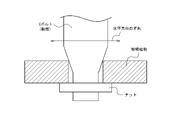
- Non-Patent Document 1 As shown in FIG. 11, by processing the tip of the shank of the bolt into a tapered shape, deviation in the vertical direction (extending direction of the shank) is less likely to occur, and the U-bolt is stabilized.
- Non-Patent Document 1 is a technique for making it difficult for vertical displacement to occur, suppressing horizontal displacement, and fixing the U-bolt by equalizing the strain of the two shafts. is difficult.
- U-bolts are used as infrastructure equipment, periodic inspections and repairs are required.
- An object of the present disclosure which has been made in view of the above-described problems, is to provide a U-bolt that can fix the U-bolt by equalizing the strain of each of the pair of shaft portions while suppressing the complication of the structure of the U-bolt. and to provide a construction method.
- the U-bolt according to the present disclosure is a U-bolt fastened to an object to be fastened. and a bridge portion connecting one end of each of the pair of shafts; and a pair of threaded portions provided at the other end of each of the pair of shafts, wherein constitutes a support surface for supporting the object to be supported.
- a construction method includes a pair of shaft portions arranged in a first direction and extending in a second direction orthogonal to the first direction, and the pair of shaft portions. and a pair of threaded portions provided at the other ends of the pair of shaft portions, wherein a part of the surface of the body portion is supported.
- a construction method for fastening a U-bolt which is configured by a support surface for supporting an object, to an object to be fastened, comprising the steps of placing a level, which is the object to be supported, on the support surface; tightening the threaded portion with a nut based on the degree.
- a construction method includes a pair of shaft portions arranged in a first direction and extending in a second direction orthogonal to the first direction, and the pair of shaft portions. and a pair of threaded portions provided at the other ends of the pair of shaft portions, wherein a part of the surface of the body portion is supported.
- a construction method for fastening a U-bolt configured by a support surface for supporting an object to an object to be fastened comprising the steps of arranging a first gyro sensor as the object to be fastened on the support surface; placing a second gyro sensor on the object; and tightening the threaded portion with a nut based on the angle detected by the first gyro sensor and the angle detected by the second gyro sensor. , including.
- the U-bolt and the construction method according to the present disclosure it is possible to fix the U-bolt by equalizing the strain of each of the pair of shaft portions while suppressing the complication of the structure of the U-bolt.
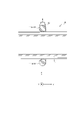
- FIG. 4 is a diagram showing another example of U-bolts according to the first embodiment; It is a figure which shows the example which has arrange
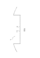
- 1B is a diagram showing a modification of the support surface shown in FIG. 1A;
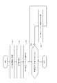
- FIG. 4 is a flow chart showing an example of an operation for fastening a U-bolt according to the first embodiment;
- FIG. 2B is a view showing a modification of the U-bolt shown in FIG.
- FIG. 2A; 2C is a view showing a modification of the U-bolt shown in FIG. 2B;
- FIG. 6B is a cross-sectional view of the U-bolt shown in FIG. 6A along AA.
- FIG. It is a figure showing an example of U bolt concerning a 2nd embodiment.
- FIG. 10 is a diagram showing another example of U-bolts according to the second embodiment; It is a figure showing an example of U bolt concerning a 3rd embodiment. It is a flow chart which shows an example of operation for fastening U bolt concerning a 3rd embodiment.
- FIG. 5 is a diagram showing an example of the relationship between torque and strain of the shaft; It is a figure which shows the shift
- FIG. 4 is a diagram showing horizontal displacement of the shaft of a U-bolt;
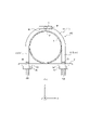
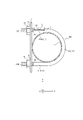
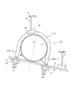
- the U-bolt 10 is made of metal such as steel. As shown in FIGS. 1A and 1B, the U-bolt 10 includes a body portion 11 including a pair of shaft portions 111A and 111B and a bridge portion 112, and a pair of threaded portions 12A and 12B.
- the shaft portions 111A and 111B are arranged in a predetermined direction and extend in a direction orthogonal to the predetermined direction.
- the direction in which the shaft portions 111A and 111B are arranged side by side is referred to as the X-axis direction (first direction), and the shaft portions 111A and 111B extend.
- a direction perpendicular to the X-axis direction and the Y-axis direction is referred to as a Z-axis direction (third direction).
- the axial part 111 when not distinguishing the axial part 111A and the axial part 111B, it is called the axial part 111.
- the shaft portion 111A and the shaft portion 111B are collectively referred to as a pair of shaft portions 111. As shown in FIG.
- the bridge portion 112 connects one end of each of the shaft portions 111A and 111B. Moreover, the bridge portion 112 is provided at one end of each of the shaft portions 111A and 111B, and can be curved in a semicircular shape. As a result, the U-bolt 10 is formed in a U-shape.
- the threaded portion 12A and the threaded portion 12B each have a threaded structure.
- the threaded portion 12A and the threaded portion 12B are provided at the other ends of the shaft portions 111A and 111B, respectively.
- the screw part 12 when not distinguishing the screw part 12A and the screw part 12B, it is called the screw part 12.
- the threaded portion 12A and the threaded portion 12B are collectively referred to as a pair of threaded portions 12. As shown in FIG.
- a fastener 1 such as piping is arranged inside the U-shaped U-bolt 10 (the space surrounded by the pair of shaft portions 111 and the bridge portion 112).
- a fastener 1 such as piping is arranged inside the U-bolt 10.
- a pair of through holes 4A and 4B provided in the object to be fastened 2 such as a supporting metal fitting is threaded from one side of the object to be fastened 2, respectively.
- 12A and threaded portion 12B are penetrated and protrude to the other side of the object 2 to be fastened.
- the threaded portion 12A and the threaded portion 12B protruding from the other side of the fastened object 2 are tightened by a nut 3A and a nut 3B.
- the nut 3A and the nut 3B each have a thread structure that engages with the thread structure of the threaded portion 12A and the threaded portion 12B.
- the fastening object 1 is sandwiched between the U-bolt 10 and the fastening object 2 and fixed.
- the through holes 4A and 4B are referred to as the through holes 4 when not distinguished from each other.
- the nuts 3A and 3B are referred to as nuts 3 when not distinguished from each other.
- Washers 5A and 5B may be interposed between the nuts 3A and 3B and the object 2 to be fastened.
- the washer 5A and the washer 5B are referred to as the washer 5 when not distinguished from each other.
- part of the surface of the main body portion 11 constitutes a support surface 11B that supports the object to be supported.
- the support surface 11B supports the object to be supported in a substantially vertical direction when the U-bolt 10 is fastened to the object 2 to be fastened.
- substantially vertical direction means that the difference between the direction in which the supporting surface 11B supports the supported object and the vertical direction is equal to or less than a predetermined value.
- the support surface 11B can be configured by a plane.
- the support surface 11B is formed so as to contact the object to be supported at one or more locations so as to support the object to be supported in a substantially vertical direction when the U bolt 10 is fastened to the object to be fastened 2. It can be configured with any shape.
- part of the surface of the bridge portion 112 constitutes a support surface 11B that supports the object to be supported in the extension direction (Y-axis direction) in which the shaft portion 111 extends.
- the support surface 11B is a plane whose vertical direction is the direction in which the shaft portion 111 extends.
- the support surface 11B of the bridge portion 112 may be a plane including the vertex O.
- the vertex O is the intersection of the support surface 11B and an imaginary straight line OX extending in the Y-axis direction, which includes the midpoint of the pair of shaft portions 111A and 111B.
- the center of the support surface 11B of the concave portion RC in the X-axis direction may be the vertex O.
- one shaft portion 111A forms a support surface 11B that supports an object to be supported in a direction (X-axis direction) orthogonal to the extending direction (Y-axis direction) in which the shaft portion 111 extends. is doing.
- the support surface 11B is a plane having a vertical direction perpendicular to the direction in which the shaft portion 111 extends.
- the support surface 11B of the shaft portion 111A is located on the opposite side of the shaft portion 111A from the side facing the other shaft portion 111B, and the support surface 11B of the shaft portion 111A extends in the extension direction. It is an orthogonal direction, and is a plane whose vertical direction is the direction from one screw portion 12A to the other shaft portion 111B.
- the main body portion 11 may include the recess RC, and the support surface 11B may be configured by the bottom surface of the recess RC.
- the bridge portion 112 has a recess RC, and the support surface 11B of the bridge portion 112 is the bottom surface of the recess RC.
- the shaft portion 111A has a recess RC, and the support surface 11B of the shaft portion 111 is the bottom surface of the recess RC.
- the level 6 is the supported object placed on the support surface 11B configured in this way.
- a level 6 measures the horizontality of the level 6 .
- the level 6 measures the levelness of the support surface 11B on which the level 6 is arranged.
- Horizontalness is the degree of horizontality, and may be indicated by, for example, an angle with the horizontal direction.
- the angle of the direction in which the supporting surface 11B supports the object to be supported is known with respect to the extending direction. Therefore, based on the horizontality measured by the level 6, the operator can recognize the angle of the extending direction of the shaft portion 111 with respect to the horizontal direction.
- the U-bolt is fastened to the fastened object 2 arranged with the Y-axis direction as the vertical direction and the Y-axis direction as the vertical direction.
- the level 6 is arranged on the support surface 11B of the bridge portion 112 as the above-described supported body, as shown in FIG. 2A. Specifically, the level 6 is arranged on the support surface 11B so that the extending direction of the vial of the level 6 is approximately horizontal.
- the U-bolt is fastened to the fastened object 2 arranged with the Y-axis direction as the horizontal direction and the Y-axis direction as the vertical direction.
- the level 6 is arranged on the supporting surface 11B of the shaft portion 111A as the above-described supported body, as shown in FIG. 2B. Specifically, the level 6 is arranged on the support surface 11B so that the extending direction of the vial of the level 6 is approximately horizontal.
- the length d 1 of the support surface 11B is equal to or greater than the length d 2 of the level 6 .
- the length d2 of the level 6 is the length in the direction in which the vial of the level 6 extends.
- the length d 1 of the support surface 11B can be approximately the same as the length d 2 of the level 6 .
- the coefficient of friction of the support surface 11B is equal to or greater than a predetermined value.
- the predetermined value is appropriately designed depending on the material forming the housing of the level 6 .
- the support surface 11B may have a plurality of grooves 11B1 so that the coefficient of friction is equal to or greater than a predetermined value.
- the support surface 11B has a plurality of grooves 11B1 over the entire support surface 11B, but a portion of the support surface 11B may have a plurality of grooves 11B1.
- the support surface 11B may have a friction coefficient equal to or higher than a predetermined value by having unevenness, grained surface, or the like on at least a part of the support surface 11B.
- the support surface 11B may have any shape that fits with the side of the level 6 that contacts the support surface 11B.
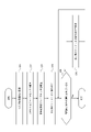
- FIG. 4 is a flow chart showing an example of the operation for fastening the U-bolt 10 according to the first embodiment.
- the operation for fastening the U-bolt 10 described with reference to FIG. 4 corresponds to the construction method for fastening the U-bolt 10 according to the first embodiment.
- step S11 the operator causes the threaded portion 12 of the U-bolt 10 to pass through the through-hole 4.
- step S12 the operator places the level 6, which is the object to be supported, on the support surface 11B.
- step S13 the operator tightens the threaded portion 12 with the nut 3 based on the horizontality indicated by the level 6. Specifically, the operator tightens the threaded portion 12 to the nut 3 so that the horizontality detected by the level 6 is within a predetermined range.
- step S14 the worker determines whether or not the fastening end condition is satisfied.
- the worker can use any method for determining whether or not the fastening end condition is satisfied. For example, when the torque of the threaded portion 12, which is measured using a torque wrench, reaches a specified value, and the horizontality detected by the level gauge 6 is within a predetermined range, , it may be determined whether or not the fastening termination condition is satisfied.
- the level 6 detects If the horizontality obtained is within a predetermined range, it may be determined that the fastening termination condition is satisfied.
- the tightening end condition is satisfied. judge not.
- the operator also determines that the fastening end condition is not satisfied when the horizontality detected by the level 6 is not within the predetermined range.
- step S14 When it is determined in step S14 that the tightening end condition is satisfied, the operator ends the operation for tightening the U-bolt 10. If it is determined in step S14 that the tightening end condition is not satisfied, the operator changes the tightening of the threaded portion 12 to the nut 3 in step S15. Here, the operator changes the tightening so that the horizontality detected by the level gauge 6 is within a predetermined range. At this time, the operator may change the tightening of one of the shaft portions 111A and 111B, or may change the tightening of both the shaft portions 111A and 111B.
- step S15 When the tightening of the threaded portion 12 to the nut 3 is changed in step S15, the process returns to step S14 to repeat the process.
- part of the surface of the body portion 11 of the U-bolt 10 constitutes the support surface 11B that supports the object to be supported.
- the operator can stably arrange the level 6 on the support surface 11B. Therefore, based on the levelness detected by the level 6, the operator places the U-bolt 10 on the object to be fastened 2 so that the extending direction of the shaft portion 111 is substantially perpendicular to the surface of the object to be fastened 2. can be concluded. Therefore, the operator can fix the U-bolt by equalizing the strain of each of the pair of shaft portions while suppressing the complication of the structure of the U-bolt 10 . Accordingly, the worker can firmly fix the fastener 1 .
- a portion of the surface of the bridge portion 112 constitutes a support surface 11B that supports the object to be supported in the extending direction of the shaft portion 111.
- the operator can stably arrange the level 6 on the bridge portion 112 .
- the worker attaches the U bolt to the fastened object 2 having a plane perpendicular to the horizontal direction on the side to which the fastened object 1 is to be fixed. 10 can be properly fastened.
- the operator can fasten the U-bolt 10 to the object 2 to be fastened such that the extending directions of the pair of shaft portions 111 are substantially perpendicular to the plane of the object 2 to be fastened.
- a part of the surface of one shaft portion 111 constitutes a support surface 11B that supports an object to be supported in a direction perpendicular to the direction in which the shaft portion 111 extends.
- the operator can stably arrange the level 6 on the shaft portion 111A.
- the worker appropriately attaches the U-bolt 10 to the fastened object 2 having a plane with the horizontal direction as the vertical direction on the side to which the fastened object 1 is to be fixed. can be concluded.
- the operator can fasten the U-bolt 10 to the object 2 to be fastened such that the extending directions of the pair of shaft portions 111 are substantially orthogonal to the surface of the object 2 to be fastened.
- the center of the support surface 11B of the recess RC in the X-axis direction is the apex O
- the two side surfaces 11S of the recess RC the length L from the end on the support surface side to the end on the opening end side is substantially the same.
- the body portion 11 of the U-bolt 10 may further have a convex portion CV.
- the support surface 11B can be part of the surface of the convex portion CV.
- the support surface 11B may be the surface of the convex portion CV opposite to the surface of the convex portion CV that contacts the body portion 11 .
- the convex portion CV is provided so as to abut on the bridge portion 112 .
- the support surface 11B is a plane whose vertical direction is the direction in which the shaft portion 111 extends.
- the convex portion CV is provided so as to abut on one shaft portion 111 .
- the support surface 11B is a plane having a vertical direction perpendicular to the direction in which the shaft portion 111 extends.
- the convex portion CV can be made removable from the main body portion 11 .
- the convex portion CV is attached to the main body portion 11 when performing construction for fastening the main body portion 11 and the thread portion 12 of the U-bolt 10 to the object to be fastened 2, and the convex portion CV is attached to the main body portion 11 before and after the construction.
- the CV can be removed from the body portion 11 . Therefore, an operator can easily configure the U-bolt 10 of this embodiment.
- ⁇ Second embodiment> (Configuration of U bolt) 7A and 7B are diagrams showing configuration examples of the U-bolt 10 according to the second embodiment of the present disclosure.
- the U-bolt 10 according to the second embodiment includes a body portion 11 including a pair of shaft portions 111A and 111B and a bridge portion 112, and a pair of screws. It has a portion 12A and a threaded portion 12B.
- the level 6 according to the second embodiment further includes a magnet 61, unlike the level 6 according to the first embodiment.
- the magnet 61 may be provided at any position on the level 6.
- the magnet 61 may be provided on the side of the level 6 that contacts the support surface 11B of the main body 11 .
- the construction method for fastening the U bolts 10 according to the second embodiment is the same as the construction method for fastening the U bolts 10 according to the first embodiment.
- the level 6 having the magnets 61 is arranged on the support surface 11B.
- the level 6 placed on the support surface 11B of the main body 11 of the U-bolt 10 made of ferromagnetic metal such as steel is displaced relative to the main body 11. can be suppressed.
- the level 6 is further prevented from being displaced relative to the main body 11. can be suppressed.
- FIG. 8 is a diagram showing a configuration example of the U-bolt 10 according to the third embodiment of the present disclosure.
- the U-bolt 10 according to the third embodiment includes a body portion 11 including a pair of shaft portions 111A and 111B and a bridge portion 112, and a pair of screws. It has a portion 12A and a threaded portion 12B.
- the pair of threads 12A and 12B of the U-bolt 10 shown in FIG. 8 is the same as the pair of threads 12A and 12B of the U-bolt 10 described with reference to FIG. 1A in the first embodiment.
- a portion of the surface of the main body portion 11 in the third embodiment is constituted by a support surface 11B, like the portion of the surface of the U-bolt 10 according to the first embodiment.
- the support surface 11B in the present embodiment extends in a direction forming a known predetermined angle ⁇ (the direction along which the dashed line Xb extends in FIG. 8) with respect to the extending direction (the direction along which the dashed line Xa extends in FIG. 8). configured to support a supported object;
- the supported object placed on the support surface 11B of this embodiment is the U-bolt gyro sensor (first gyro sensor) 7 .
- a gyro sensor (second gyro sensor) 8 for a fastening object is arranged on the fastening object 2 .
- the support surface 11B is formed by the bottom surface of the recess RC included in the main body 11, but the present invention is not limited to this. Alternatively, it can be part of the surface of the projection CV provided on the U-bolt 10 .
- the U-bolt gyro sensor 7 detects an angle ⁇ 1 of the U-bolt gyro sensor 7 with respect to the reference direction.
- the reference direction may be, for example, the vertical direction, but may be any other predetermined direction.
- the angle ⁇ 1 detected by the U-bolt gyro sensor 7 is the angle formed by the direction orthogonal to the direction in which the U-bolt gyro sensor 7 extends with respect to the vertical direction.
- the gyro sensor 8 for fastening object is arranged on the fastening object 2 .
- the gyro sensor 8 for the object to be fastened detects an angle ⁇ 2 of the gyro sensor 8 for the object to be fastened with respect to the reference direction.
- the angle .theta.2 detected by the U-bolt gyro sensor 8 is the angle formed by the direction orthogonal to the direction in which the U-bolt gyro sensor 8 extends with respect to the vertical direction.
- the U-bolt gyro sensor 7 when the angle difference ⁇ 1 ⁇ 2 between the angle ⁇ 1 detected by the U-bolt gyro sensor 7 and the angle ⁇ 2 detected by the fastened object gyro sensor 8 is a predetermined angle ⁇ , the U-bolt The extending direction of the shaft portion 111 of the 10 is substantially orthogonal to the surface of the object to be fastened 2 . Therefore, based on the angle difference ⁇ 1 ⁇ 2 and the predetermined angle ⁇ , the operator can determine whether or not the shaft portions 111A and 111B are substantially evenly tightened to the nuts 3A and 3B, respectively.
- the operator assumes that the shaft portions 111A and 111B are substantially evenly tightened to the nuts 3A and 3B, respectively. can judge. Further, when the angle difference ⁇ 1 ⁇ 2 is not within the predetermined range from the predetermined angle ⁇ , the operator can determine that the shaft portions 111A and 111B are not substantially evenly tightened to the nuts 3A and 3B, respectively. can.
- the predetermined angle ⁇ is 0°.
- the angle difference ⁇ 1- ⁇ 2 when the angle difference ⁇ 1- ⁇ 2 is within a predetermined range from a predetermined angle of 0°, the operator sees that the shaft portions 111A and 111B are substantially evenly tightened by the nuts 3A and 3B, respectively. It can be determined that As another example, when the supporting surface 11B is configured to support the object to be supported in the direction orthogonal to the extending direction of the shaft portion 11, the predetermined angle ⁇ is 90°. With such a configuration, when the angle difference ⁇ 1 ⁇ 2 is within a predetermined range from the predetermined angle 90°, the operator can see that the shaft portions 111A and 111B are substantially evenly tightened by the nuts 3A and 3B, respectively. It can be determined that
- FIG. 9 is a flow chart showing an example of the operation for fastening the U-bolt 10 according to the third embodiment.
- the operation for fastening the U-bolt 10 described with reference to FIG. 9 corresponds to the construction method for fastening the U-bolt 10 according to the third embodiment.
- step S21 the operator passes the threaded portion 12 of the U-bolt 10 through the through-hole 4.
- step S22 the operator places the U-bolt gyro sensor 7, which is the object to be supported, on the support surface 11B of the main body 11.
- step S23 the operator places the fastened object gyro sensor 8 on the fastened object 2.
- step S24 the operator tightens the screw portion 12 with the nut 3 based on the angle ⁇ 1 detected by the U-bolt gyro sensor 7 and the angle ⁇ 2 detected by the fastened object gyro sensor 8. Specifically, the operator tightens the threaded portion 12 with the nut 3 so that the angle difference ⁇ 1 ⁇ 2 is within a predetermined range from the known predetermined angle ⁇ .
- step S25 the worker determines whether or not the fastening end condition is satisfied.
- the worker can use any method for determining whether or not the fastening end condition is satisfied. For example, when the torque of the threaded portion 12, which is measured using a torque wrench, reaches a specified value, the angle difference ⁇ 1 ⁇ 2 is within a predetermined range from a known predetermined angle ⁇ . In this case, it may be determined whether or not the fastening end condition is satisfied.
- the angle difference ⁇ 1 ⁇ 2 is If it is within a predetermined range from a known predetermined angle ⁇ , it may be determined that the fastening end condition is satisfied. In this case, if the threaded portion 12 is not completely tightened by the nut 3, that is, if the nut 3 can be further rotated in the direction in which the threaded portion 12 is tightened, the tightening end condition is satisfied. judge not. The operator also determines that the fastening end condition is not satisfied when the angle difference ⁇ 1 ⁇ 2 is not within the predetermined range from the known predetermined angle ⁇ .
- step S25 When it is determined in step S25 that the tightening end condition is satisfied, the operator ends the operation for tightening the U-bolt 10. If it is determined in step S24 that the tightening end condition is not satisfied, the operator changes the tightening of the threaded portion 12 to the nut 3 in step S26. Here, the operator changes the tightening so that the angle difference ⁇ 1 ⁇ 2 is within a predetermined range from the known predetermined angle ⁇ . Moreover, the operator may change the tightening of one of the shaft portions 111A and 111B, or may change the tightening of both the shaft portions 111A and 111B.
- step S26 When the tightening of the threaded portion 12 to the nut 3 is changed in step S26, the process returns to step S25 to repeat the process.
- step S23 is executed after the process of step S22 is executed, but the present invention is not limited to this.
- the process of step S22 may be executed after the process of step S23 is executed, or the process of step S22 and the process of step S23 may be executed at the same timing.
- the object to be supported is the U-bolt gyro sensor 7, and the object to be fastened 2 is provided with the gyro sensor 8 for the object to be fastened. Therefore, even when the direction in which the object to be fastened 2 is arranged is unknown, the U-bolt 10 can be fixed by equalizing the strain of each of the pair of shaft portions while suppressing the complication of the structure of the U-bolt. can be done. Therefore, the operator can fix the U-bolt 10 by equalizing the strain of each of the pair of shaft portions while suppressing the complication of the structure of the U-bolt 10 . Accordingly, the worker can firmly fix the fastener 1 .
Landscapes
- Engineering & Computer Science (AREA)
- General Engineering & Computer Science (AREA)
- Mechanical Engineering (AREA)
- Physics & Mathematics (AREA)
- General Physics & Mathematics (AREA)
- Connection Of Plates (AREA)
- Clamps And Clips (AREA)
- Bridges Or Land Bridges (AREA)
Priority Applications (3)
| Application Number | Priority Date | Filing Date | Title |
|---|---|---|---|
| PCT/JP2021/002390 WO2022157961A1 (ja) | 2021-01-25 | 2021-01-25 | Uボルト及び施工方法 |
| US18/273,002 US20240309903A1 (en) | 2021-01-25 | 2021-01-25 | U-bolt and construction method |
| JP2022576927A JP7538444B2 (ja) | 2021-01-25 | 2021-01-25 | Uボルト及び施工方法 |
Applications Claiming Priority (1)
| Application Number | Priority Date | Filing Date | Title |
|---|---|---|---|
| PCT/JP2021/002390 WO2022157961A1 (ja) | 2021-01-25 | 2021-01-25 | Uボルト及び施工方法 |
Publications (1)
| Publication Number | Publication Date |
|---|---|
| WO2022157961A1 true WO2022157961A1 (ja) | 2022-07-28 |
Family
ID=82548634
Family Applications (1)
| Application Number | Title | Priority Date | Filing Date |
|---|---|---|---|
| PCT/JP2021/002390 Ceased WO2022157961A1 (ja) | 2021-01-25 | 2021-01-25 | Uボルト及び施工方法 |
Country Status (3)
| Country | Link |
|---|---|
| US (1) | US20240309903A1 (https=) |
| JP (1) | JP7538444B2 (https=) |
| WO (1) | WO2022157961A1 (https=) |
Citations (2)
| Publication number | Priority date | Publication date | Assignee | Title |
|---|---|---|---|---|
| US5804737A (en) * | 1997-08-29 | 1998-09-08 | Mccoy Bolt Works, Inc. | U-bolt testing apparatus |
| JP3088650U (ja) * | 2002-03-18 | 2002-09-20 | 株式会社南星 | インターロック装置付き2胴ウインチ装着のバックホーの転倒防止装置 |
Family Cites Families (10)
| Publication number | Priority date | Publication date | Assignee | Title |
|---|---|---|---|---|
| US5014940A (en) * | 1989-08-28 | 1991-05-14 | Zsi, Inc. | Clamp assembly |
| US5215281A (en) * | 1991-09-27 | 1993-06-01 | Zsi, Inc. | Two-piece cushion insert for U-bolt clamp assembly |
| US5205022A (en) * | 1992-06-09 | 1993-04-27 | Norton John F | U-bolt clamp assembly |
| FR2768485B1 (fr) * | 1997-09-18 | 1999-12-10 | Cogema | Systeme de supportage pour tuyauteries en galeries techniques, notamment de l'industrie nucleaire |
| WO2016159245A1 (ja) * | 2015-03-31 | 2016-10-06 | 株式会社NejiLaw | 通電路付部材及び通電路のパターニング方法、部材変化計測方法 |
| US20230114691A1 (en) * | 2020-03-18 | 2023-04-13 | Nippon Telegraph And Telephone Corporation | U-bolt mounting jig and u-bolt mounting method |
| JPWO2022162899A1 (https=) * | 2021-01-29 | 2022-08-04 | ||
| WO2022162897A1 (ja) * | 2021-01-29 | 2022-08-04 | 日本電信電話株式会社 | Uボルト、施工方法及び検出装置 |
| US20250027768A1 (en) * | 2021-11-15 | 2025-01-23 | Nippon Telegraph And Telephone Corporation | U-bolt, detection device, and detection method |
| US11802578B1 (en) * | 2022-07-06 | 2023-10-31 | All Rite Products, Inc. | Article cushioning interface and related methods |
-
2021
- 2021-01-25 WO PCT/JP2021/002390 patent/WO2022157961A1/ja not_active Ceased
- 2021-01-25 JP JP2022576927A patent/JP7538444B2/ja active Active
- 2021-01-25 US US18/273,002 patent/US20240309903A1/en active Pending
Patent Citations (2)
| Publication number | Priority date | Publication date | Assignee | Title |
|---|---|---|---|---|
| US5804737A (en) * | 1997-08-29 | 1998-09-08 | Mccoy Bolt Works, Inc. | U-bolt testing apparatus |
| JP3088650U (ja) * | 2002-03-18 | 2002-09-20 | 株式会社南星 | インターロック装置付き2胴ウインチ装着のバックホーの転倒防止装置 |
Also Published As
| Publication number | Publication date |
|---|---|
| US20240309903A1 (en) | 2024-09-19 |
| JPWO2022157961A1 (https=) | 2022-07-28 |
| JP7538444B2 (ja) | 2024-08-22 |
Similar Documents
| Publication | Publication Date | Title |
|---|---|---|
| JP2011153868A (ja) | ラバーブッシュの特性試験装置用治具 | |
| TWI789981B (zh) | 可安裝在牆壁之托架總成 | |
| WO2022157961A1 (ja) | Uボルト及び施工方法 | |
| KR102271533B1 (ko) | 안정성이 향상된 교량받침 구조 | |
| JP5947696B2 (ja) | 緩み止め具及び当該緩み止め具を備えた減震ストッパ構造 | |
| JP2008285931A (ja) | 支承の高さ調整装置 | |
| JP2014009547A (ja) | コンクリート部材の補強装置に用いられるロック機能付き継手 | |
| JP2019132841A (ja) | 締着力検出装置 | |
| JP2014051818A (ja) | ブレース取付具 | |
| US11198326B2 (en) | Axle system | |
| JP2019007134A (ja) | 既設フーチングの補強方法 | |
| JP7485992B2 (ja) | Uボルト及び施工方法 | |
| KR101948977B1 (ko) | 와셔 및 이를 포함한 지그 | |
| JP7397700B2 (ja) | アンカーボルトの鉛直据付方法 | |
| PL243537B1 (pl) | Uchwyt do belek ze wstępnym napięciem osiowym o warunkach brzegowych typu obustronne zamurowanie do montażu na wzbudniku elektromechanicznym | |
| JP2003002555A (ja) | エレベータのレール芯出し装置 | |
| JP4460377B2 (ja) | クリーンルーム用の根太とそれを用いたクリーンルーム根太床 | |
| JP6013050B2 (ja) | コンクリート部材の補強装置に用いられる継手 | |
| JP4969107B2 (ja) | 位置基準台装置 | |
| JP2010164153A (ja) | 緩み防止ボルト及び緩み防止ナット | |
| JP7417083B2 (ja) | 接触部材、接合構造および部材の接合方法 | |
| JP4761957B2 (ja) | 鉄筋用ナット | |
| WO2019059073A1 (ja) | 制震壁 | |
| JP4084315B2 (ja) | ブレース連結構造及びその設置方法 | |
| US20210381835A1 (en) | Inertial measuring unit with reduced sensitivity to thermomechanical constraints |
Legal Events
| Date | Code | Title | Description |
|---|---|---|---|
| 121 | Ep: the epo has been informed by wipo that ep was designated in this application |
Ref document number: 21921069 Country of ref document: EP Kind code of ref document: A1 |
|
| ENP | Entry into the national phase |
Ref document number: 2022576927 Country of ref document: JP Kind code of ref document: A |
|
| WWE | Wipo information: entry into national phase |
Ref document number: 18273002 Country of ref document: US |
|
| NENP | Non-entry into the national phase |
Ref country code: DE |
|
| 122 | Ep: pct application non-entry in european phase |
Ref document number: 21921069 Country of ref document: EP Kind code of ref document: A1 |