WO2022157961A1 - U-bolt and construction method - Google Patents
U-bolt and construction method Download PDFInfo
- Publication number
- WO2022157961A1 WO2022157961A1 PCT/JP2021/002390 JP2021002390W WO2022157961A1 WO 2022157961 A1 WO2022157961 A1 WO 2022157961A1 JP 2021002390 W JP2021002390 W JP 2021002390W WO 2022157961 A1 WO2022157961 A1 WO 2022157961A1
- Authority
- WO
- WIPO (PCT)
- Prior art keywords
- bolt
- support surface
- pair
- fastened
- supported
- Prior art date
Links
- 238000010276 construction Methods 0.000 title claims description 19
- 238000000034 method Methods 0.000 description 15
- 238000010586 diagram Methods 0.000 description 9
- 238000006073 displacement reaction Methods 0.000 description 6
- 229910000831 Steel Inorganic materials 0.000 description 4
- 239000010959 steel Substances 0.000 description 4
- 239000002184 metal Substances 0.000 description 3
- 230000004048 modification Effects 0.000 description 3
- 238000012986 modification Methods 0.000 description 3
- 239000002131 composite material Substances 0.000 description 1
- 230000005294 ferromagnetic effect Effects 0.000 description 1
- 238000007689 inspection Methods 0.000 description 1
- 239000000463 material Substances 0.000 description 1
- 230000000737 periodic effect Effects 0.000 description 1
- 230000008439 repair process Effects 0.000 description 1
Images


Classifications
-
- F—MECHANICAL ENGINEERING; LIGHTING; HEATING; WEAPONS; BLASTING
- F16—ENGINEERING ELEMENTS AND UNITS; GENERAL MEASURES FOR PRODUCING AND MAINTAINING EFFECTIVE FUNCTIONING OF MACHINES OR INSTALLATIONS; THERMAL INSULATION IN GENERAL
- F16B—DEVICES FOR FASTENING OR SECURING CONSTRUCTIONAL ELEMENTS OR MACHINE PARTS TOGETHER, e.g. NAILS, BOLTS, CIRCLIPS, CLAMPS, CLIPS OR WEDGES; JOINTS OR JOINTING
- F16B31/00—Screwed connections specially modified in view of tensile load; Break-bolts
- F16B31/02—Screwed connections specially modified in view of tensile load; Break-bolts for indicating the attainment of a particular tensile load or limiting tensile load
-
- F—MECHANICAL ENGINEERING; LIGHTING; HEATING; WEAPONS; BLASTING
- F16—ENGINEERING ELEMENTS AND UNITS; GENERAL MEASURES FOR PRODUCING AND MAINTAINING EFFECTIVE FUNCTIONING OF MACHINES OR INSTALLATIONS; THERMAL INSULATION IN GENERAL
- F16B—DEVICES FOR FASTENING OR SECURING CONSTRUCTIONAL ELEMENTS OR MACHINE PARTS TOGETHER, e.g. NAILS, BOLTS, CIRCLIPS, CLAMPS, CLIPS OR WEDGES; JOINTS OR JOINTING
- F16B35/00—Screw-bolts; Stay-bolts; Screw-threaded studs; Screws; Set screws
-
- G—PHYSICS
- G01—MEASURING; TESTING
- G01L—MEASURING FORCE, STRESS, TORQUE, WORK, MECHANICAL POWER, MECHANICAL EFFICIENCY, OR FLUID PRESSURE
- G01L5/00—Apparatus for, or methods of, measuring force, work, mechanical power, or torque, specially adapted for specific purposes
Definitions
- This disclosure relates to U-bolts and construction methods.
- U-bolts are used to fix fasteners such as piping to fastened objects such as frames and walls.
- a U-bolt is a U-shaped bolt in which two linear shafts are connected by a bridge.
- FIG. 10 is a diagram showing the relationship between the torque for tightening the nut on the shaft of the U-bolt and the strain of each of the two shafts.
- one of the two shafts (shaft A) is first tightened with a torque wrench, and then the other shaft (shaft B) is tightened with a torque wrench.
- strain ⁇ of shaft portions A and B strain ⁇ A of shaft portion A and strain ⁇ B of shaft portion B ).
- shaft A which is tightened first, is tightened more than shaft B with a smaller torque. That is, the relationship between strain and torque does not match between the left and right shaft portions A and B. FIG. Therefore, even if the tightening force of the nut is controlled by a torque wrench, since the nuts are alternately tightened on the two shafts, the difference in the correlation between the strain and the torque between the shafts A and B causes , it is difficult to fix the U-bolt by equalizing the strain of the two shafts.
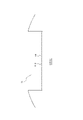
- Non-Patent Document 1 As shown in FIG. 11, by processing the tip of the shank of the bolt into a tapered shape, deviation in the vertical direction (extending direction of the shank) is less likely to occur, and the U-bolt is stabilized.
- Non-Patent Document 1 is a technique for making it difficult for vertical displacement to occur, suppressing horizontal displacement, and fixing the U-bolt by equalizing the strain of the two shafts. is difficult.
- U-bolts are used as infrastructure equipment, periodic inspections and repairs are required.
- An object of the present disclosure which has been made in view of the above-described problems, is to provide a U-bolt that can fix the U-bolt by equalizing the strain of each of the pair of shaft portions while suppressing the complication of the structure of the U-bolt. and to provide a construction method.
- the U-bolt according to the present disclosure is a U-bolt fastened to an object to be fastened. and a bridge portion connecting one end of each of the pair of shafts; and a pair of threaded portions provided at the other end of each of the pair of shafts, wherein constitutes a support surface for supporting the object to be supported.
- a construction method includes a pair of shaft portions arranged in a first direction and extending in a second direction orthogonal to the first direction, and the pair of shaft portions. and a pair of threaded portions provided at the other ends of the pair of shaft portions, wherein a part of the surface of the body portion is supported.
- a construction method for fastening a U-bolt which is configured by a support surface for supporting an object, to an object to be fastened, comprising the steps of placing a level, which is the object to be supported, on the support surface; tightening the threaded portion with a nut based on the degree.
- a construction method includes a pair of shaft portions arranged in a first direction and extending in a second direction orthogonal to the first direction, and the pair of shaft portions. and a pair of threaded portions provided at the other ends of the pair of shaft portions, wherein a part of the surface of the body portion is supported.
- a construction method for fastening a U-bolt configured by a support surface for supporting an object to an object to be fastened comprising the steps of arranging a first gyro sensor as the object to be fastened on the support surface; placing a second gyro sensor on the object; and tightening the threaded portion with a nut based on the angle detected by the first gyro sensor and the angle detected by the second gyro sensor. , including.
- the U-bolt and the construction method according to the present disclosure it is possible to fix the U-bolt by equalizing the strain of each of the pair of shaft portions while suppressing the complication of the structure of the U-bolt.
- FIG. 4 is a diagram showing another example of U-bolts according to the first embodiment; It is a figure which shows the example which has arrange
- 1B is a diagram showing a modification of the support surface shown in FIG. 1A;
- FIG. 4 is a flow chart showing an example of an operation for fastening a U-bolt according to the first embodiment;
- FIG. 2B is a view showing a modification of the U-bolt shown in FIG.
- FIG. 2A; 2C is a view showing a modification of the U-bolt shown in FIG. 2B;
- FIG. 6B is a cross-sectional view of the U-bolt shown in FIG. 6A along AA.
- FIG. It is a figure showing an example of U bolt concerning a 2nd embodiment.
- FIG. 10 is a diagram showing another example of U-bolts according to the second embodiment; It is a figure showing an example of U bolt concerning a 3rd embodiment. It is a flow chart which shows an example of operation for fastening U bolt concerning a 3rd embodiment.
- FIG. 5 is a diagram showing an example of the relationship between torque and strain of the shaft; It is a figure which shows the shift
- FIG. 4 is a diagram showing horizontal displacement of the shaft of a U-bolt;
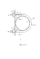
- the U-bolt 10 is made of metal such as steel. As shown in FIGS. 1A and 1B, the U-bolt 10 includes a body portion 11 including a pair of shaft portions 111A and 111B and a bridge portion 112, and a pair of threaded portions 12A and 12B.
- the shaft portions 111A and 111B are arranged in a predetermined direction and extend in a direction orthogonal to the predetermined direction.
- the direction in which the shaft portions 111A and 111B are arranged side by side is referred to as the X-axis direction (first direction), and the shaft portions 111A and 111B extend.
- a direction perpendicular to the X-axis direction and the Y-axis direction is referred to as a Z-axis direction (third direction).
- the axial part 111 when not distinguishing the axial part 111A and the axial part 111B, it is called the axial part 111.
- the shaft portion 111A and the shaft portion 111B are collectively referred to as a pair of shaft portions 111. As shown in FIG.
- the bridge portion 112 connects one end of each of the shaft portions 111A and 111B. Moreover, the bridge portion 112 is provided at one end of each of the shaft portions 111A and 111B, and can be curved in a semicircular shape. As a result, the U-bolt 10 is formed in a U-shape.
- the threaded portion 12A and the threaded portion 12B each have a threaded structure.
- the threaded portion 12A and the threaded portion 12B are provided at the other ends of the shaft portions 111A and 111B, respectively.
- the screw part 12 when not distinguishing the screw part 12A and the screw part 12B, it is called the screw part 12.
- the threaded portion 12A and the threaded portion 12B are collectively referred to as a pair of threaded portions 12. As shown in FIG.
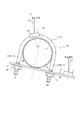
- a fastener 1 such as piping is arranged inside the U-shaped U-bolt 10 (the space surrounded by the pair of shaft portions 111 and the bridge portion 112).
- a fastener 1 such as piping is arranged inside the U-bolt 10.
- a pair of through holes 4A and 4B provided in the object to be fastened 2 such as a supporting metal fitting is threaded from one side of the object to be fastened 2, respectively.
- 12A and threaded portion 12B are penetrated and protrude to the other side of the object 2 to be fastened.
- the threaded portion 12A and the threaded portion 12B protruding from the other side of the fastened object 2 are tightened by a nut 3A and a nut 3B.
- the nut 3A and the nut 3B each have a thread structure that engages with the thread structure of the threaded portion 12A and the threaded portion 12B.
- the fastening object 1 is sandwiched between the U-bolt 10 and the fastening object 2 and fixed.
- the through holes 4A and 4B are referred to as the through holes 4 when not distinguished from each other.
- the nuts 3A and 3B are referred to as nuts 3 when not distinguished from each other.
- Washers 5A and 5B may be interposed between the nuts 3A and 3B and the object 2 to be fastened.
- the washer 5A and the washer 5B are referred to as the washer 5 when not distinguished from each other.
- part of the surface of the main body portion 11 constitutes a support surface 11B that supports the object to be supported.
- the support surface 11B supports the object to be supported in a substantially vertical direction when the U-bolt 10 is fastened to the object 2 to be fastened.
- substantially vertical direction means that the difference between the direction in which the supporting surface 11B supports the supported object and the vertical direction is equal to or less than a predetermined value.
- the support surface 11B can be configured by a plane.
- the support surface 11B is formed so as to contact the object to be supported at one or more locations so as to support the object to be supported in a substantially vertical direction when the U bolt 10 is fastened to the object to be fastened 2. It can be configured with any shape.
- part of the surface of the bridge portion 112 constitutes a support surface 11B that supports the object to be supported in the extension direction (Y-axis direction) in which the shaft portion 111 extends.
- the support surface 11B is a plane whose vertical direction is the direction in which the shaft portion 111 extends.
- the support surface 11B of the bridge portion 112 may be a plane including the vertex O.
- the vertex O is the intersection of the support surface 11B and an imaginary straight line OX extending in the Y-axis direction, which includes the midpoint of the pair of shaft portions 111A and 111B.
- the center of the support surface 11B of the concave portion RC in the X-axis direction may be the vertex O.
- one shaft portion 111A forms a support surface 11B that supports an object to be supported in a direction (X-axis direction) orthogonal to the extending direction (Y-axis direction) in which the shaft portion 111 extends. is doing.
- the support surface 11B is a plane having a vertical direction perpendicular to the direction in which the shaft portion 111 extends.
- the support surface 11B of the shaft portion 111A is located on the opposite side of the shaft portion 111A from the side facing the other shaft portion 111B, and the support surface 11B of the shaft portion 111A extends in the extension direction. It is an orthogonal direction, and is a plane whose vertical direction is the direction from one screw portion 12A to the other shaft portion 111B.
- the main body portion 11 may include the recess RC, and the support surface 11B may be configured by the bottom surface of the recess RC.
- the bridge portion 112 has a recess RC, and the support surface 11B of the bridge portion 112 is the bottom surface of the recess RC.
- the shaft portion 111A has a recess RC, and the support surface 11B of the shaft portion 111 is the bottom surface of the recess RC.
- the level 6 is the supported object placed on the support surface 11B configured in this way.
- a level 6 measures the horizontality of the level 6 .
- the level 6 measures the levelness of the support surface 11B on which the level 6 is arranged.
- Horizontalness is the degree of horizontality, and may be indicated by, for example, an angle with the horizontal direction.
- the angle of the direction in which the supporting surface 11B supports the object to be supported is known with respect to the extending direction. Therefore, based on the horizontality measured by the level 6, the operator can recognize the angle of the extending direction of the shaft portion 111 with respect to the horizontal direction.
- the U-bolt is fastened to the fastened object 2 arranged with the Y-axis direction as the vertical direction and the Y-axis direction as the vertical direction.
- the level 6 is arranged on the support surface 11B of the bridge portion 112 as the above-described supported body, as shown in FIG. 2A. Specifically, the level 6 is arranged on the support surface 11B so that the extending direction of the vial of the level 6 is approximately horizontal.
- the U-bolt is fastened to the fastened object 2 arranged with the Y-axis direction as the horizontal direction and the Y-axis direction as the vertical direction.
- the level 6 is arranged on the supporting surface 11B of the shaft portion 111A as the above-described supported body, as shown in FIG. 2B. Specifically, the level 6 is arranged on the support surface 11B so that the extending direction of the vial of the level 6 is approximately horizontal.
- the length d 1 of the support surface 11B is equal to or greater than the length d 2 of the level 6 .
- the length d2 of the level 6 is the length in the direction in which the vial of the level 6 extends.
- the length d 1 of the support surface 11B can be approximately the same as the length d 2 of the level 6 .
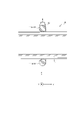
- the coefficient of friction of the support surface 11B is equal to or greater than a predetermined value.
- the predetermined value is appropriately designed depending on the material forming the housing of the level 6 .
- the support surface 11B may have a plurality of grooves 11B1 so that the coefficient of friction is equal to or greater than a predetermined value.
- the support surface 11B has a plurality of grooves 11B1 over the entire support surface 11B, but a portion of the support surface 11B may have a plurality of grooves 11B1.
- the support surface 11B may have a friction coefficient equal to or higher than a predetermined value by having unevenness, grained surface, or the like on at least a part of the support surface 11B.
- the support surface 11B may have any shape that fits with the side of the level 6 that contacts the support surface 11B.
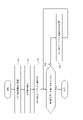
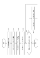
- FIG. 4 is a flow chart showing an example of the operation for fastening the U-bolt 10 according to the first embodiment.
- the operation for fastening the U-bolt 10 described with reference to FIG. 4 corresponds to the construction method for fastening the U-bolt 10 according to the first embodiment.
- step S11 the operator causes the threaded portion 12 of the U-bolt 10 to pass through the through-hole 4.
- step S12 the operator places the level 6, which is the object to be supported, on the support surface 11B.
- step S13 the operator tightens the threaded portion 12 with the nut 3 based on the horizontality indicated by the level 6. Specifically, the operator tightens the threaded portion 12 to the nut 3 so that the horizontality detected by the level 6 is within a predetermined range.
- step S14 the worker determines whether or not the fastening end condition is satisfied.
- the worker can use any method for determining whether or not the fastening end condition is satisfied. For example, when the torque of the threaded portion 12, which is measured using a torque wrench, reaches a specified value, and the horizontality detected by the level gauge 6 is within a predetermined range, , it may be determined whether or not the fastening termination condition is satisfied.
- the level 6 detects If the horizontality obtained is within a predetermined range, it may be determined that the fastening termination condition is satisfied.
- the tightening end condition is satisfied. judge not.
- the operator also determines that the fastening end condition is not satisfied when the horizontality detected by the level 6 is not within the predetermined range.
- step S14 When it is determined in step S14 that the tightening end condition is satisfied, the operator ends the operation for tightening the U-bolt 10. If it is determined in step S14 that the tightening end condition is not satisfied, the operator changes the tightening of the threaded portion 12 to the nut 3 in step S15. Here, the operator changes the tightening so that the horizontality detected by the level gauge 6 is within a predetermined range. At this time, the operator may change the tightening of one of the shaft portions 111A and 111B, or may change the tightening of both the shaft portions 111A and 111B.
- step S15 When the tightening of the threaded portion 12 to the nut 3 is changed in step S15, the process returns to step S14 to repeat the process.
- part of the surface of the body portion 11 of the U-bolt 10 constitutes the support surface 11B that supports the object to be supported.
- the operator can stably arrange the level 6 on the support surface 11B. Therefore, based on the levelness detected by the level 6, the operator places the U-bolt 10 on the object to be fastened 2 so that the extending direction of the shaft portion 111 is substantially perpendicular to the surface of the object to be fastened 2. can be concluded. Therefore, the operator can fix the U-bolt by equalizing the strain of each of the pair of shaft portions while suppressing the complication of the structure of the U-bolt 10 . Accordingly, the worker can firmly fix the fastener 1 .
- a portion of the surface of the bridge portion 112 constitutes a support surface 11B that supports the object to be supported in the extending direction of the shaft portion 111.
- the operator can stably arrange the level 6 on the bridge portion 112 .
- the worker attaches the U bolt to the fastened object 2 having a plane perpendicular to the horizontal direction on the side to which the fastened object 1 is to be fixed. 10 can be properly fastened.
- the operator can fasten the U-bolt 10 to the object 2 to be fastened such that the extending directions of the pair of shaft portions 111 are substantially perpendicular to the plane of the object 2 to be fastened.
- a part of the surface of one shaft portion 111 constitutes a support surface 11B that supports an object to be supported in a direction perpendicular to the direction in which the shaft portion 111 extends.
- the operator can stably arrange the level 6 on the shaft portion 111A.
- the worker appropriately attaches the U-bolt 10 to the fastened object 2 having a plane with the horizontal direction as the vertical direction on the side to which the fastened object 1 is to be fixed. can be concluded.
- the operator can fasten the U-bolt 10 to the object 2 to be fastened such that the extending directions of the pair of shaft portions 111 are substantially orthogonal to the surface of the object 2 to be fastened.
- the center of the support surface 11B of the recess RC in the X-axis direction is the apex O
- the two side surfaces 11S of the recess RC the length L from the end on the support surface side to the end on the opening end side is substantially the same.
- the body portion 11 of the U-bolt 10 may further have a convex portion CV.
- the support surface 11B can be part of the surface of the convex portion CV.
- the support surface 11B may be the surface of the convex portion CV opposite to the surface of the convex portion CV that contacts the body portion 11 .
- the convex portion CV is provided so as to abut on the bridge portion 112 .
- the support surface 11B is a plane whose vertical direction is the direction in which the shaft portion 111 extends.
- the convex portion CV is provided so as to abut on one shaft portion 111 .
- the support surface 11B is a plane having a vertical direction perpendicular to the direction in which the shaft portion 111 extends.
- the convex portion CV can be made removable from the main body portion 11 .
- the convex portion CV is attached to the main body portion 11 when performing construction for fastening the main body portion 11 and the thread portion 12 of the U-bolt 10 to the object to be fastened 2, and the convex portion CV is attached to the main body portion 11 before and after the construction.
- the CV can be removed from the body portion 11 . Therefore, an operator can easily configure the U-bolt 10 of this embodiment.
- ⁇ Second embodiment> (Configuration of U bolt) 7A and 7B are diagrams showing configuration examples of the U-bolt 10 according to the second embodiment of the present disclosure.
- the U-bolt 10 according to the second embodiment includes a body portion 11 including a pair of shaft portions 111A and 111B and a bridge portion 112, and a pair of screws. It has a portion 12A and a threaded portion 12B.
- the level 6 according to the second embodiment further includes a magnet 61, unlike the level 6 according to the first embodiment.
- the magnet 61 may be provided at any position on the level 6.
- the magnet 61 may be provided on the side of the level 6 that contacts the support surface 11B of the main body 11 .
- the construction method for fastening the U bolts 10 according to the second embodiment is the same as the construction method for fastening the U bolts 10 according to the first embodiment.
- the level 6 having the magnets 61 is arranged on the support surface 11B.
- the level 6 placed on the support surface 11B of the main body 11 of the U-bolt 10 made of ferromagnetic metal such as steel is displaced relative to the main body 11. can be suppressed.
- the level 6 is further prevented from being displaced relative to the main body 11. can be suppressed.
- FIG. 8 is a diagram showing a configuration example of the U-bolt 10 according to the third embodiment of the present disclosure.
- the U-bolt 10 according to the third embodiment includes a body portion 11 including a pair of shaft portions 111A and 111B and a bridge portion 112, and a pair of screws. It has a portion 12A and a threaded portion 12B.
- the pair of threads 12A and 12B of the U-bolt 10 shown in FIG. 8 is the same as the pair of threads 12A and 12B of the U-bolt 10 described with reference to FIG. 1A in the first embodiment.
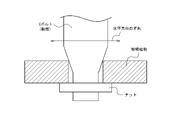
- a portion of the surface of the main body portion 11 in the third embodiment is constituted by a support surface 11B, like the portion of the surface of the U-bolt 10 according to the first embodiment.
- the support surface 11B in the present embodiment extends in a direction forming a known predetermined angle ⁇ (the direction along which the dashed line Xb extends in FIG. 8) with respect to the extending direction (the direction along which the dashed line Xa extends in FIG. 8). configured to support a supported object;
- the supported object placed on the support surface 11B of this embodiment is the U-bolt gyro sensor (first gyro sensor) 7 .
- a gyro sensor (second gyro sensor) 8 for a fastening object is arranged on the fastening object 2 .
- the support surface 11B is formed by the bottom surface of the recess RC included in the main body 11, but the present invention is not limited to this. Alternatively, it can be part of the surface of the projection CV provided on the U-bolt 10 .
- the U-bolt gyro sensor 7 detects an angle ⁇ 1 of the U-bolt gyro sensor 7 with respect to the reference direction.
- the reference direction may be, for example, the vertical direction, but may be any other predetermined direction.
- the angle ⁇ 1 detected by the U-bolt gyro sensor 7 is the angle formed by the direction orthogonal to the direction in which the U-bolt gyro sensor 7 extends with respect to the vertical direction.
- the gyro sensor 8 for fastening object is arranged on the fastening object 2 .
- the gyro sensor 8 for the object to be fastened detects an angle ⁇ 2 of the gyro sensor 8 for the object to be fastened with respect to the reference direction.
- the angle .theta.2 detected by the U-bolt gyro sensor 8 is the angle formed by the direction orthogonal to the direction in which the U-bolt gyro sensor 8 extends with respect to the vertical direction.
- the U-bolt gyro sensor 7 when the angle difference ⁇ 1 ⁇ 2 between the angle ⁇ 1 detected by the U-bolt gyro sensor 7 and the angle ⁇ 2 detected by the fastened object gyro sensor 8 is a predetermined angle ⁇ , the U-bolt The extending direction of the shaft portion 111 of the 10 is substantially orthogonal to the surface of the object to be fastened 2 . Therefore, based on the angle difference ⁇ 1 ⁇ 2 and the predetermined angle ⁇ , the operator can determine whether or not the shaft portions 111A and 111B are substantially evenly tightened to the nuts 3A and 3B, respectively.
- the operator assumes that the shaft portions 111A and 111B are substantially evenly tightened to the nuts 3A and 3B, respectively. can judge. Further, when the angle difference ⁇ 1 ⁇ 2 is not within the predetermined range from the predetermined angle ⁇ , the operator can determine that the shaft portions 111A and 111B are not substantially evenly tightened to the nuts 3A and 3B, respectively. can.
- the predetermined angle ⁇ is 0°.
- the angle difference ⁇ 1- ⁇ 2 when the angle difference ⁇ 1- ⁇ 2 is within a predetermined range from a predetermined angle of 0°, the operator sees that the shaft portions 111A and 111B are substantially evenly tightened by the nuts 3A and 3B, respectively. It can be determined that As another example, when the supporting surface 11B is configured to support the object to be supported in the direction orthogonal to the extending direction of the shaft portion 11, the predetermined angle ⁇ is 90°. With such a configuration, when the angle difference ⁇ 1 ⁇ 2 is within a predetermined range from the predetermined angle 90°, the operator can see that the shaft portions 111A and 111B are substantially evenly tightened by the nuts 3A and 3B, respectively. It can be determined that
- FIG. 9 is a flow chart showing an example of the operation for fastening the U-bolt 10 according to the third embodiment.
- the operation for fastening the U-bolt 10 described with reference to FIG. 9 corresponds to the construction method for fastening the U-bolt 10 according to the third embodiment.
- step S21 the operator passes the threaded portion 12 of the U-bolt 10 through the through-hole 4.
- step S22 the operator places the U-bolt gyro sensor 7, which is the object to be supported, on the support surface 11B of the main body 11.
- step S23 the operator places the fastened object gyro sensor 8 on the fastened object 2.
- step S24 the operator tightens the screw portion 12 with the nut 3 based on the angle ⁇ 1 detected by the U-bolt gyro sensor 7 and the angle ⁇ 2 detected by the fastened object gyro sensor 8. Specifically, the operator tightens the threaded portion 12 with the nut 3 so that the angle difference ⁇ 1 ⁇ 2 is within a predetermined range from the known predetermined angle ⁇ .
- step S25 the worker determines whether or not the fastening end condition is satisfied.
- the worker can use any method for determining whether or not the fastening end condition is satisfied. For example, when the torque of the threaded portion 12, which is measured using a torque wrench, reaches a specified value, the angle difference ⁇ 1 ⁇ 2 is within a predetermined range from a known predetermined angle ⁇ . In this case, it may be determined whether or not the fastening end condition is satisfied.
- the angle difference ⁇ 1 ⁇ 2 is If it is within a predetermined range from a known predetermined angle ⁇ , it may be determined that the fastening end condition is satisfied. In this case, if the threaded portion 12 is not completely tightened by the nut 3, that is, if the nut 3 can be further rotated in the direction in which the threaded portion 12 is tightened, the tightening end condition is satisfied. judge not. The operator also determines that the fastening end condition is not satisfied when the angle difference ⁇ 1 ⁇ 2 is not within the predetermined range from the known predetermined angle ⁇ .
- step S25 When it is determined in step S25 that the tightening end condition is satisfied, the operator ends the operation for tightening the U-bolt 10. If it is determined in step S24 that the tightening end condition is not satisfied, the operator changes the tightening of the threaded portion 12 to the nut 3 in step S26. Here, the operator changes the tightening so that the angle difference ⁇ 1 ⁇ 2 is within a predetermined range from the known predetermined angle ⁇ . Moreover, the operator may change the tightening of one of the shaft portions 111A and 111B, or may change the tightening of both the shaft portions 111A and 111B.
- step S26 When the tightening of the threaded portion 12 to the nut 3 is changed in step S26, the process returns to step S25 to repeat the process.
- step S23 is executed after the process of step S22 is executed, but the present invention is not limited to this.
- the process of step S22 may be executed after the process of step S23 is executed, or the process of step S22 and the process of step S23 may be executed at the same timing.
- the object to be supported is the U-bolt gyro sensor 7, and the object to be fastened 2 is provided with the gyro sensor 8 for the object to be fastened. Therefore, even when the direction in which the object to be fastened 2 is arranged is unknown, the U-bolt 10 can be fixed by equalizing the strain of each of the pair of shaft portions while suppressing the complication of the structure of the U-bolt. can be done. Therefore, the operator can fix the U-bolt 10 by equalizing the strain of each of the pair of shaft portions while suppressing the complication of the structure of the U-bolt 10 . Accordingly, the worker can firmly fix the fastener 1 .
Abstract
A U-bolt (10) according to the present disclosure is fastened to a fastening target (2), and comprises: a body portion (11) which includes a pair of shaft portions (111) that are arranged in a first direction and extend in a second direction perpendicular to the first direction and a bridge portion (112) that connects together one end of each of the pair of shaft portions (111); and a pair of screw portions (12) which are provided the other end of respective shaft portions (111), wherein a portion of the surface of the body portion (11) constitutes a support surface (11B) for supporting an object to be supported.
Description
本開示は、Uボルト及び施工方法に関する。
This disclosure relates to U-bolts and construction methods.
従来、配管等の締結物を架台、壁面等の被締結物に固定するために、Uボルトが用いられている。Uボルトとは、2つの直線状の軸部が橋梁部により連結されたU字形状のボルトである。Uボルトの内側に締結物を挟んだ状態で被締結物に設けられた2つの貫通孔それぞれにUボルトの軸部を挿入し、2つの軸部それぞれの端部からナットで締め付けることで、Uボルトと被締結物とで締結物を挟んで固定することができる。
Conventionally, U-bolts are used to fix fasteners such as piping to fastened objects such as frames and walls. A U-bolt is a U-shaped bolt in which two linear shafts are connected by a bridge. By inserting the shaft of the U bolt into each of the two through-holes provided in the object to be fastened with the object to be fastened inside the U bolt and tightening the nuts from the ends of each of the two shafts, the U The object to be fastened can be fixed by sandwiching it between the bolt and the object to be fastened.
Uボルトで締結物を被締結物に固定する場合、Uボルトを被締結物に対して垂直に固定する必要がある。しかしながら、Uボルトは、2つの軸部のうち片方ずつしかナットの締め付けを行うことができないため、Uボルトを左右均等に固定することが困難である。
When fixing an object to be fastened with a U-bolt, it is necessary to fix the U-bolt vertically to the object to be fastened. However, in the U-bolt, the nut can be tightened only one of the two shaft portions, so it is difficult to evenly fix the U-bolt to the left and right.
図10は、Uボルトの軸部にナットを締め付けるトルクと、2本の軸部それぞれのひずみとの関係を示す図である。図10においては、2本の軸部のうちの一方の軸部(軸部A)を先にトルクレンチで締め付け、次に、他方の軸部(軸部B)をトルクレンチで締め付けた場合の、トルクTと軸部A,Bのひずみε(軸部AのひずみεA及び軸部BのひずみεB)との関係を示す図である。
FIG. 10 is a diagram showing the relationship between the torque for tightening the nut on the shaft of the U-bolt and the strain of each of the two shafts. In FIG. 10, one of the two shafts (shaft A) is first tightened with a torque wrench, and then the other shaft (shaft B) is tightened with a torque wrench. , and strain ε of shaft portions A and B (strain ε A of shaft portion A and strain ε B of shaft portion B ).
図10に示すように、先に締め付けた軸部Aの方が、軸部Bよりも小さいトルクで多く締め付けられる。すなわち、ひずみとトルクとの関係が左右の軸部Aと軸部Bとで一致しない。そのため、トルクレンチによりナットの締結力を管理しても、2本の軸部に対してナットを交互に締め付けるため、軸部Aと軸部Bとでのひずみとトルクとの相関関係の相違により、2本の軸部のひずみを均等にしてUボルトを固定することが困難である。
As shown in FIG. 10, shaft A, which is tightened first, is tightened more than shaft B with a smaller torque. That is, the relationship between strain and torque does not match between the left and right shaft portions A and B. FIG. Therefore, even if the tightening force of the nut is controlled by a torque wrench, since the nuts are alternately tightened on the two shafts, the difference in the correlation between the strain and the torque between the shafts A and B causes , it is difficult to fix the U-bolt by equalizing the strain of the two shafts.
非特許文献1には、図11に示すように、ボルトの軸部の先端をテーパ状に加工することで、鉛直方向(軸部の延在方向)のずれを生じにくくし、Uボルトを安定して固定する技術が記載されている。
In Non-Patent Document 1, as shown in FIG. 11, by processing the tip of the shank of the bolt into a tapered shape, deviation in the vertical direction (extending direction of the shank) is less likely to occur, and the U-bolt is stabilized. A technique for fixing by
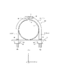
Uボルトを被締結物に固定する場合、図12に示すように、水平方向(左右方向)のずれが生じ、水平方向に傾いた状態でUボルトが固定されることがある。上述した非特許文献1に記載の技術は、鉛直方向のずれを生じにくくするための技術であり、水平方向のずれを抑制し、2本の軸部のひずみを均等にしてUボルトを固定することは困難である。また、インフラ設備としてUボルトを使用する場合、定期的な点検及び補修が必要となるため、Uボルト本体を複雑な構造にすると、点検及び補修に手間がかかってしまうという問題がある。
When fixing the U-bolt to the object to be fastened, as shown in FIG. 12, there is a possibility that the U-bolt is fixed in a horizontally inclined state due to a horizontal (lateral) deviation. The technique described in Non-Patent Document 1 mentioned above is a technique for making it difficult for vertical displacement to occur, suppressing horizontal displacement, and fixing the U-bolt by equalizing the strain of the two shafts. is difficult. In addition, when U-bolts are used as infrastructure equipment, periodic inspections and repairs are required.
上記のような問題点に鑑みてなされた本開示の目的は、Uボルトの構造の複雑化を抑制しつつ、一対の軸部それぞれのひずみを均等にしてUボルトを固定することができるUボルト及び施工方法を提供することにある。
SUMMARY OF THE INVENTION An object of the present disclosure, which has been made in view of the above-described problems, is to provide a U-bolt that can fix the U-bolt by equalizing the strain of each of the pair of shaft portions while suppressing the complication of the structure of the U-bolt. and to provide a construction method.
上記課題を解決するため、本開示に係るUボルトは、被締結物に締結されるUボルトにおいて、第1の方向に並び、前記第1の方向と直交する第2の方向に延在する一対の軸部、及び前記一対の軸部それぞれの一端を連結する橋梁部を含む本体部と、前記一対の軸部それぞれの他端に設けられている一対のねじ部と、を備え、前記本体部の表面の一部は、被支持物体を支持する支持面を構成している。
In order to solve the above problems, the U-bolt according to the present disclosure is a U-bolt fastened to an object to be fastened. and a bridge portion connecting one end of each of the pair of shafts; and a pair of threaded portions provided at the other end of each of the pair of shafts, wherein constitutes a support surface for supporting the object to be supported.
また、上記課題を解決するため、本開示に係る施工方法は、第1の方向に並び、前記第1の方向と直交する第2の方向に延在する一対の軸部、及び前記一対の軸部それぞれの一端を連結する橋梁部を含む本体部と、前記一対の軸部それぞれの他端に設けられている一対のねじ部と、を備え、前記本体部の表面の一部は、被支持物体を支持する支持面により構成されているUボルトを被締結物に締結する施工方法であって、前記支持面に前記被支持物体である水平器を配置するステップと、前記水平器が示す水平度に基づいて、前記ねじ部をナットにより締め付けるステップと、を含む。
Further, in order to solve the above problems, a construction method according to the present disclosure includes a pair of shaft portions arranged in a first direction and extending in a second direction orthogonal to the first direction, and the pair of shaft portions. and a pair of threaded portions provided at the other ends of the pair of shaft portions, wherein a part of the surface of the body portion is supported. A construction method for fastening a U-bolt, which is configured by a support surface for supporting an object, to an object to be fastened, comprising the steps of placing a level, which is the object to be supported, on the support surface; tightening the threaded portion with a nut based on the degree.
また、上記課題を解決するため、本開示に係る施工方法は、第1の方向に並び、前記第1の方向と直交する第2の方向に延在する一対の軸部、及び前記一対の軸部それぞれの一端を連結する橋梁部を含む本体部と、前記一対の軸部それぞれの他端に設けられている一対のねじ部と、を備え、前記本体部の表面の一部は、被支持物体を支持する支持面により構成されているUボルトを被締結物に締結する施工方法であって、前記支持面に前記被支持物体である第1のジャイロセンサを配置するステップと、前記被締結物に第2のジャイロセンサを配置するステップと、前記第1のジャイロセンサによって検出された角度、及び前記第2のジャイロセンサによって検出された角度に基づいて、前記ねじ部をナットにより締め付けるステップと、を含む。
Further, in order to solve the above problems, a construction method according to the present disclosure includes a pair of shaft portions arranged in a first direction and extending in a second direction orthogonal to the first direction, and the pair of shaft portions. and a pair of threaded portions provided at the other ends of the pair of shaft portions, wherein a part of the surface of the body portion is supported. A construction method for fastening a U-bolt configured by a support surface for supporting an object to an object to be fastened, comprising the steps of arranging a first gyro sensor as the object to be fastened on the support surface; placing a second gyro sensor on the object; and tightening the threaded portion with a nut based on the angle detected by the first gyro sensor and the angle detected by the second gyro sensor. ,including.
本開示に係るUボルト及び施工方法によれば、Uボルトの構造の複雑化を抑制しつつ、一対の軸部それぞれのひずみを均等にしてUボルトを固定することができる。
According to the U-bolt and the construction method according to the present disclosure, it is possible to fix the U-bolt by equalizing the strain of each of the pair of shaft portions while suppressing the complication of the structure of the U-bolt.
以下、本開示の実施の形態について図面を参照して説明する。
Hereinafter, embodiments of the present disclosure will be described with reference to the drawings.
<第1の実施形態>
(Uボルトの構成)
図1A及び図1Bは、本開示の第1の実施形態に係るUボルト10の構成例を示す図である。 <First embodiment>
(Configuration of U bolt)
1A and 1B are diagrams showing configuration examples of aU-bolt 10 according to the first embodiment of the present disclosure.
(Uボルトの構成)
図1A及び図1Bは、本開示の第1の実施形態に係るUボルト10の構成例を示す図である。 <First embodiment>
(Configuration of U bolt)
1A and 1B are diagrams showing configuration examples of a
本実施形態に係るUボルト10は、鋼等の金属によって構成されている。図1A及び図1Bに示すように、Uボルト10は、一対の軸部111A及び軸部111B、並びに橋梁部112を含む本体部11と、一対のねじ部12A及びねじ部12Bとを備える。
The U-bolt 10 according to this embodiment is made of metal such as steel. As shown in FIGS. 1A and 1B, the U-bolt 10 includes a body portion 11 including a pair of shaft portions 111A and 111B and a bridge portion 112, and a pair of threaded portions 12A and 12B.
軸部111A及び軸部111Bは、所定の方向に並び、該所定の方向と直交する方向に延在する。以下では、図1A及び図1Bに示すように、軸部111A及び軸部111Bが並んで配置される方向をX軸方向(第1の方向)と称し、軸部111A及び軸部111Bが延在する方向をY軸方向(第2の方向)と称し、X軸方向及びY軸方向と直交する方向をZ軸方向(第3の方向)と称する。また、以下では、軸部111A及び軸部111Bを区別しない場合には、軸部111と称する。また、以下では、軸部111A及び軸部111Bを合わせて一対の軸部111と称する。
The shaft portions 111A and 111B are arranged in a predetermined direction and extend in a direction orthogonal to the predetermined direction. Hereinafter, as shown in FIGS. 1A and 1B, the direction in which the shaft portions 111A and 111B are arranged side by side is referred to as the X-axis direction (first direction), and the shaft portions 111A and 111B extend. A direction perpendicular to the X-axis direction and the Y-axis direction is referred to as a Z-axis direction (third direction). Moreover, below, when not distinguishing the axial part 111A and the axial part 111B, it is called the axial part 111. As shown in FIG. Moreover, below, the shaft portion 111A and the shaft portion 111B are collectively referred to as a pair of shaft portions 111. As shown in FIG.
橋梁部112は、軸部111A及び軸部111Bそれぞれの一端を連結する。また、橋梁部112は、軸部111A及び軸部111Bそれぞれの一端に設けられ、半円状に湾曲した形状とすることができる。これにより、Uボルト10はU字形状に形成される。
The bridge portion 112 connects one end of each of the shaft portions 111A and 111B. Moreover, the bridge portion 112 is provided at one end of each of the shaft portions 111A and 111B, and can be curved in a semicircular shape. As a result, the U-bolt 10 is formed in a U-shape.
ねじ部12A及びねじ部12Bは、それぞれねじ山構造を有する。ねじ部12A及びねじ部12Bは、軸部111A及び軸部111Bそれぞれの他端に設けられている。また、以下では、ねじ部12A及びねじ部12Bを区別しない場合には、ねじ部12と称する。また、以下では、ねじ部12A及びねじ部12Bを合わせて一対のねじ部12と称する。
The threaded portion 12A and the threaded portion 12B each have a threaded structure. The threaded portion 12A and the threaded portion 12B are provided at the other ends of the shaft portions 111A and 111B, respectively. Moreover, below, when not distinguishing the screw part 12A and the screw part 12B, it is called the screw part 12. As shown in FIG. Moreover, below, the threaded portion 12A and the threaded portion 12B are collectively referred to as a pair of threaded portions 12. As shown in FIG.
U字形状のUボルト10の内側(一対の軸部111及び橋梁部112により囲まれる空間)には、配管等の締結物1が配置される。締結物1がUボルト10の内側に配置された状態で、支持金物等の被締結物2に設けられた一対の貫通孔4A及び貫通孔4Bに、被締結物2の一面側からそれぞれねじ部12A及びねじ部12Bが貫通され、被締結物2の他面側に突出する。被締結物2の他面側から突出したねじ部12A及びねじ部12Bは、ナット3A及びナット3Bにより締め付けられる。なお、ナット3A及びナット3Bは、ねじ部12A及びねじ部12Bのねじ山構造と螺合するねじ山構造をそれぞれ有している。これにより、締結物1は、Uボルト10と被締結物2とに挟まれて固定される。以下では、貫通孔4A及び貫通孔4Bを区別しない場合には、貫通孔4と称する。また、ナット3A及びナット3Bを区別しない場合には、ナット3と称する。なお、ナット3A及びナット3Bと被締結物2との間に座金5A及び座金5Bが挟まれていてもよい。座金5A及び座金5Bを区別しない場合には、座金5と称する。
Inside the U-shaped U-bolt 10 (the space surrounded by the pair of shaft portions 111 and the bridge portion 112), a fastener 1 such as piping is arranged. In a state in which the fastening object 1 is arranged inside the U-bolt 10, a pair of through holes 4A and 4B provided in the object to be fastened 2 such as a supporting metal fitting is threaded from one side of the object to be fastened 2, respectively. 12A and threaded portion 12B are penetrated and protrude to the other side of the object 2 to be fastened. The threaded portion 12A and the threaded portion 12B protruding from the other side of the fastened object 2 are tightened by a nut 3A and a nut 3B. The nut 3A and the nut 3B each have a thread structure that engages with the thread structure of the threaded portion 12A and the threaded portion 12B. As a result, the fastening object 1 is sandwiched between the U-bolt 10 and the fastening object 2 and fixed. Hereinafter, the through holes 4A and 4B are referred to as the through holes 4 when not distinguished from each other. The nuts 3A and 3B are referred to as nuts 3 when not distinguished from each other. Washers 5A and 5B may be interposed between the nuts 3A and 3B and the object 2 to be fastened. The washer 5A and the washer 5B are referred to as the washer 5 when not distinguished from each other.
本実施形態においては、本体部11の表面の一部は、被支持物体を支持する支持面11Bを構成している。具体的には、支持面11Bは、Uボルト10が被締結物2に締結された状態において、被支持物体を略鉛直方向に支持する。「略鉛直方向」とは、支持面11Bが被支持物体を支持する方向の、鉛直方向との差分が所定値以下であることを示す。支持面11Bは、平面によって構成することができる。また、支持面11Bは、Uボルト10が被締結物2に締結された状態において、被支持物体を略鉛直方向に支持するように、1ヶ所以上において被支持物体に当接するように形成された任意の形状によって構成することができる。
In this embodiment, part of the surface of the main body portion 11 constitutes a support surface 11B that supports the object to be supported. Specifically, the support surface 11B supports the object to be supported in a substantially vertical direction when the U-bolt 10 is fastened to the object 2 to be fastened. "Substantially vertical direction" means that the difference between the direction in which the supporting surface 11B supports the supported object and the vertical direction is equal to or less than a predetermined value. The support surface 11B can be configured by a plane. In addition, the support surface 11B is formed so as to contact the object to be supported at one or more locations so as to support the object to be supported in a substantially vertical direction when the U bolt 10 is fastened to the object to be fastened 2. It can be configured with any shape.
図1Aに示す例では、橋梁部112の表面の一部は、軸部111が延在する延在方向(Y軸方向)に被支持物体を支持する支持面11Bを構成している。本例において、支持面11Bは、軸部111が延在している延在方向を垂線方向とする平面である。例えば、橋梁部112の支持面11Bは、頂点Oを含む平面であってもよい。頂点Oは、一対の軸部111A及び軸部111Bの中点を含む、Y軸方向に延在する仮想的な直線OXと支持面11Bとの交点である。また、X軸方向における、凹部RCの支持面11Bの中心は、頂点Oであってもよい。
In the example shown in FIG. 1A, part of the surface of the bridge portion 112 constitutes a support surface 11B that supports the object to be supported in the extension direction (Y-axis direction) in which the shaft portion 111 extends. In this example, the support surface 11B is a plane whose vertical direction is the direction in which the shaft portion 111 extends. For example, the support surface 11B of the bridge portion 112 may be a plane including the vertex O. The vertex O is the intersection of the support surface 11B and an imaginary straight line OX extending in the Y-axis direction, which includes the midpoint of the pair of shaft portions 111A and 111B. Also, the center of the support surface 11B of the concave portion RC in the X-axis direction may be the vertex O.
図1Bに示す例では、一方の軸部111Aは、軸部111が延在する延在方向(Y軸方向)に直交する方向(X軸方向)に被支持物体を支持する支持面11Bを構成している。本例において、支持面11Bは、軸部111が延在している延在方向に直交する方向を垂線方向とする平面である。具体的には、軸部111Aの支持面11Bは、軸部111Aの、他方の軸部111Bに対向する側と反対側に位置しており、軸部111Aの支持面11Bは、延在方向の直交方向であって、一方のねじ部12Aから他方の軸部111Bに向かう方向を垂線方向とする平面である。
In the example shown in FIG. 1B, one shaft portion 111A forms a support surface 11B that supports an object to be supported in a direction (X-axis direction) orthogonal to the extending direction (Y-axis direction) in which the shaft portion 111 extends. is doing. In this example, the support surface 11B is a plane having a vertical direction perpendicular to the direction in which the shaft portion 111 extends. Specifically, the support surface 11B of the shaft portion 111A is located on the opposite side of the shaft portion 111A from the side facing the other shaft portion 111B, and the support surface 11B of the shaft portion 111A extends in the extension direction. It is an orthogonal direction, and is a plane whose vertical direction is the direction from one screw portion 12A to the other shaft portion 111B.
また、本実施形態において、本体部11は凹部RCを含み、支持面11Bは、凹部RCの底面によって構成されていてもよい。図1Aに示す例では、橋梁部112は凹部RCを有し、橋梁部112の支持面11Bは、該凹部RCの底面である。図1Bに示す例では、軸部111Aは凹部RCを有し、軸部111の支持面11Bは、該凹部RCの底面である。
Further, in the present embodiment, the main body portion 11 may include the recess RC, and the support surface 11B may be configured by the bottom surface of the recess RC. In the example shown in FIG. 1A, the bridge portion 112 has a recess RC, and the support surface 11B of the bridge portion 112 is the bottom surface of the recess RC. In the example shown in FIG. 1B, the shaft portion 111A has a recess RC, and the support surface 11B of the shaft portion 111 is the bottom surface of the recess RC.
本実施形態において、このように構成された支持面11Bに配置される被支持物体は、水平器6である。水平器6は、該水平器6の水平度を計測する。これによって、水平器6は、該水平器6が配置された支持面11Bの水平度を計測する。水平度とは、水平となっている度合いであって、例えば、水平方向とのなす角によって示されてもよい。支持面11Bが被支持物体を支持する方向の、延在方向に対する角度は既知である。したがって、作業者は、水平器6によって計測された水平度に基づいて、軸部111が延在する延在方向の水平方向に対する角度を認識することができる。
In this embodiment, the level 6 is the supported object placed on the support surface 11B configured in this way. A level 6 measures the horizontality of the level 6 . Thereby, the level 6 measures the levelness of the support surface 11B on which the level 6 is arranged. Horizontalness is the degree of horizontality, and may be indicated by, for example, an angle with the horizontal direction. The angle of the direction in which the supporting surface 11B supports the object to be supported is known with respect to the extending direction. Therefore, based on the horizontality measured by the level 6, the operator can recognize the angle of the extending direction of the shaft portion 111 with respect to the horizontal direction.
図1Aに示すような、橋梁部112が支持面11Bを有する構成において、Uボルトは、Y軸方向を鉛直方向とし、該Y軸方向を垂線方向として配置された被締結物2に締結される。水平器6は、上述した被支持体として、図2Aに示すように、橋梁部112の支持面11Bに配置される。具体的には、水平器6は、該水平器6が有する気泡管の延在方向が略水平となるように、支持面11Bに配置される。
In the configuration in which the bridge portion 112 has the support surface 11B as shown in FIG. 1A, the U-bolt is fastened to the fastened object 2 arranged with the Y-axis direction as the vertical direction and the Y-axis direction as the vertical direction. . The level 6 is arranged on the support surface 11B of the bridge portion 112 as the above-described supported body, as shown in FIG. 2A. Specifically, the level 6 is arranged on the support surface 11B so that the extending direction of the vial of the level 6 is approximately horizontal.
図1Bに示すように、軸部111Aが支持面11Bを有する構成において、Uボルトは、Y軸方向を水平方向とし、該Y軸方向を垂線方向として配置された被締結物2に締結される。水平器6は、上述した被支持体として、図2Bに示すように、軸部111Aの支持面11Bに配置される。具体的には、水平器6は、該水平器6が有する気泡管の延在方向が略水平となるように、支持面11Bに配置される。
As shown in FIG. 1B, in the configuration in which the shaft portion 111A has the support surface 11B, the U-bolt is fastened to the fastened object 2 arranged with the Y-axis direction as the horizontal direction and the Y-axis direction as the vertical direction. . The level 6 is arranged on the supporting surface 11B of the shaft portion 111A as the above-described supported body, as shown in FIG. 2B. Specifically, the level 6 is arranged on the support surface 11B so that the extending direction of the vial of the level 6 is approximately horizontal.
支持面11Bの長さd1は、水平器6の長さd2以上である。なお、水平器6の長さd2は、該水平器6が有する気泡管の延在方向における長さである。図1A及び図1Bに示すように、支持面11Bの長さd1は、水平器6の長さd2と略同一であるとすることができる。これにより、水平器6は、支持面11Bの上に配置された状態において、支持面11Bに平行な方向への変位が抑制され、安定して支持される。
The length d 1 of the support surface 11B is equal to or greater than the length d 2 of the level 6 . Note that the length d2 of the level 6 is the length in the direction in which the vial of the level 6 extends. As shown in FIGS. 1A and 1B, the length d 1 of the support surface 11B can be approximately the same as the length d 2 of the level 6 . As a result, when the level 6 is placed on the support surface 11B, displacement in the direction parallel to the support surface 11B is suppressed, and the level 6 is stably supported.
また、支持面11Bの摩擦係数は所定値以上であることが好ましい。ここで、所定値は、水平器6の筐体を構成する材料によって適宜設計される。例えば、図3に示すように、支持面11Bは、複数の溝11B1を有することによって、摩擦係数を所定値以上としてもよい。図3に示す例では、支持面11Bは、該支持面11Bの全体に複数の溝11B1を有しているが、該支持面11Bの一部に複数の溝11B1を有してもよい。また、支持面11Bは、該支持面11Bの少なくとも一部に、凹凸、砂目面等を有することによって、摩擦係数を所定値以上としてもよい。また、支持面11Bは、水平器6における、該支持面11Bに当接する側と互いに嵌合する任意の形状を有していてもよい。これにより、水平器6は、支持面11Bの上に配置された状態において、支持面11Bが水平器6を支持する方向に直交する方向への変位が抑制される。したがって、水平器6は安定して支持されるため、作業者は、高い精度で水平度を計測することができる。
Also, it is preferable that the coefficient of friction of the support surface 11B is equal to or greater than a predetermined value. Here, the predetermined value is appropriately designed depending on the material forming the housing of the level 6 . For example, as shown in FIG. 3, the support surface 11B may have a plurality of grooves 11B1 so that the coefficient of friction is equal to or greater than a predetermined value. In the example shown in FIG. 3, the support surface 11B has a plurality of grooves 11B1 over the entire support surface 11B, but a portion of the support surface 11B may have a plurality of grooves 11B1. Further, the support surface 11B may have a friction coefficient equal to or higher than a predetermined value by having unevenness, grained surface, or the like on at least a part of the support surface 11B. Moreover, the support surface 11B may have any shape that fits with the side of the level 6 that contacts the support surface 11B. As a result, when the level 6 is placed on the support surface 11B, the support surface 11B is prevented from being displaced in the direction orthogonal to the direction in which the level 6 is supported. Therefore, since the level 6 is stably supported, the operator can measure the levelness with high accuracy.
(Uボルトの締結の施工方法)
ここで、第1の実施形態に係るUボルト10を締結するための動作について、図4を参照して説明する。図4は、第1の実施形態に係るUボルト10を締結するための動作の一例を示すフローチャートである。図4を参照して説明するUボルト10を締結するための動作は第1の実施形態に係るUボルト10を締結するための施工方法に相当する。 (Construction method for fastening U-bolts)
Here, the operation for fastening the U-bolt 10 according to the first embodiment will be described with reference to FIG. FIG. 4 is a flow chart showing an example of the operation for fastening the U-bolt 10 according to the first embodiment. The operation for fastening the U-bolt 10 described with reference to FIG. 4 corresponds to the construction method for fastening the U-bolt 10 according to the first embodiment.
ステップS11において、作業者が、Uボルト10のねじ部12を貫通孔4に貫通させる。
In step S11, the operator causes the threaded portion 12 of the U-bolt 10 to pass through the through-hole 4.
ステップS12において、作業者が、支持面11Bに被支持物体である水平器6を配置する。
In step S12, the operator places the level 6, which is the object to be supported, on the support surface 11B.
ステップS13において、作業者が、水平器6が示す水平度に基づいて、ねじ部12をナット3により締め付ける。具体的には、作業者が、水平器6によって検出された水平度が所定範囲内であるように、ねじ部12をナット3に締め付ける。
In step S13, the operator tightens the threaded portion 12 with the nut 3 based on the horizontality indicated by the level 6. Specifically, the operator tightens the threaded portion 12 to the nut 3 so that the horizontality detected by the level 6 is within a predetermined range.
ステップS14において、作業者が、締結終了条件が満たされているか否かを判定する。このとき、作業者は、締結終了条件が満たされているか否かの判定において任意の方法を用いることができる。例えば、作業者は、トルクレンチを用いて計測される、ねじ部12のトルクが規定値に到達している場合であって、水平器6によって検出された水平度が所定範囲内である場合に、締結終了条件が満たされているか否かを判定してもよい。また、作業者は、ねじ部12がナット3により完全に締め付けられている場合、すなわち、ねじ部12を締め付ける方向にナット3をさらに回転させることができない場合であって、水平器6によって検出された水平度が所定範囲内である場合に、締結終了条件が満たされていると判定してもよい。この場合、作業者は、ねじ部12がナット3により完全に締め付けられていない場合、すなわち、ねじ部12を締め付ける方向にナット3をさらに回転させることができる場合に、締結終了条件が満たされていないと判定する。また、作業者は、水平器6によって検出された水平度が所定範囲内でない場合も、締結終了条件が満たされていないと判定する。
In step S14, the worker determines whether or not the fastening end condition is satisfied. At this time, the worker can use any method for determining whether or not the fastening end condition is satisfied. For example, when the torque of the threaded portion 12, which is measured using a torque wrench, reaches a specified value, and the horizontality detected by the level gauge 6 is within a predetermined range, , it may be determined whether or not the fastening termination condition is satisfied. In addition, when the threaded portion 12 is completely tightened by the nut 3, that is, when the operator cannot further rotate the nut 3 in the direction of tightening the threaded portion 12, the level 6 detects If the horizontality obtained is within a predetermined range, it may be determined that the fastening termination condition is satisfied. In this case, if the threaded portion 12 is not completely tightened by the nut 3, that is, if the nut 3 can be further rotated in the direction in which the threaded portion 12 is tightened, the tightening end condition is satisfied. judge not. The operator also determines that the fastening end condition is not satisfied when the horizontality detected by the level 6 is not within the predetermined range.
ステップS14で締結終了条件が満たされていると判定されると、作業者が、Uボルト10を締結するための動作を終了する。ステップS14で締結終了条件が満たされていないと判定されると、ステップS15において、作業者は、ねじ部12のナット3への締め付けを変更する。ここで、作業者は、水平器6によって検出された水平度が所定範囲内であるように締め付けを変更する。このとき、作業者は、軸部111A及び軸部111Bの一方の締め付けを変更してもよいし、軸部111A及び軸部111Bの両方の締め付けを変更してもよい。
When it is determined in step S14 that the tightening end condition is satisfied, the operator ends the operation for tightening the U-bolt 10. If it is determined in step S14 that the tightening end condition is not satisfied, the operator changes the tightening of the threaded portion 12 to the nut 3 in step S15. Here, the operator changes the tightening so that the horizontality detected by the level gauge 6 is within a predetermined range. At this time, the operator may change the tightening of one of the shaft portions 111A and 111B, or may change the tightening of both the shaft portions 111A and 111B.
ステップS15でねじ部12のナット3への締め付けが変更されると、ステップS14に戻って処理を繰り返す。
When the tightening of the threaded portion 12 to the nut 3 is changed in step S15, the process returns to step S14 to repeat the process.
上述したように、第1の実施形態によれば、Uボルト10の本体部11の表面の一部は、被支持物体を支持する支持面11Bを構成している。これにより、作業者は、支持面11Bに水平器6を安定して配置することができる。このため、作業者は、水平器6によって検出された水平度に基づいて、軸部111の延在方向が被締結物2の表面に略直交するように、Uボルト10を被締結物2に締結することができる。したがって、Uボルト10の構造の複雑化を抑制しつつ、作業者は、一対の軸部それぞれのひずみを均等にしてUボルトを固定することができる。これに伴い、作業者は、強固に締結物1を固定することができる。
As described above, according to the first embodiment, part of the surface of the body portion 11 of the U-bolt 10 constitutes the support surface 11B that supports the object to be supported. Thereby, the operator can stably arrange the level 6 on the support surface 11B. Therefore, based on the levelness detected by the level 6, the operator places the U-bolt 10 on the object to be fastened 2 so that the extending direction of the shaft portion 111 is substantially perpendicular to the surface of the object to be fastened 2. can be concluded. Therefore, the operator can fix the U-bolt by equalizing the strain of each of the pair of shaft portions while suppressing the complication of the structure of the U-bolt 10 . Accordingly, the worker can firmly fix the fastener 1 .
特に、橋梁部112の表面の一部が、軸部111が延在する延在方向に被支持物体を支持する支持面11Bを構成している。これにより、作業者は、橋梁部112に水平器6を安定して配置することができる。そして、作業者は、水平器6によって計測された水平度に基づいて、締結物1を固定する側に、水平方向に直交する方向を垂線方向とする平面を有する被締結物2に、Uボルト10を適切に締結することができる。具体的には、作業者は、一対の軸部111の延在方向それぞれが被締結物2の平面に対して略直交するように、Uボルト10を被締結物2に締結することができる。
In particular, a portion of the surface of the bridge portion 112 constitutes a support surface 11B that supports the object to be supported in the extending direction of the shaft portion 111. Thereby, the operator can stably arrange the level 6 on the bridge portion 112 . Then, based on the levelness measured by the level 6, the worker attaches the U bolt to the fastened object 2 having a plane perpendicular to the horizontal direction on the side to which the fastened object 1 is to be fixed. 10 can be properly fastened. Specifically, the operator can fasten the U-bolt 10 to the object 2 to be fastened such that the extending directions of the pair of shaft portions 111 are substantially perpendicular to the plane of the object 2 to be fastened.
また、一方の軸部111の表面の一部は、軸部111が延在する延在方向と直交する方向に被支持物体を支持する支持面11Bを構成している。これにより、作業者は、軸部111Aに水平器6を安定して配置することができる。そして、作業者は、水平器6によって計測された水平度に基づいて、締結物1を固定する側に、水平方向を垂線方向とする平面を有する被締結物2に、Uボルト10を適切に締結することができる。具体的には、作業者は、一対の軸部111の延在方向それぞれが被締結物2の表面に対して略直交するように、Uボルト10を被締結物2に締結することができる。
A part of the surface of one shaft portion 111 constitutes a support surface 11B that supports an object to be supported in a direction perpendicular to the direction in which the shaft portion 111 extends. Thereby, the operator can stably arrange the level 6 on the shaft portion 111A. Then, based on the levelness measured by the level 6, the worker appropriately attaches the U-bolt 10 to the fastened object 2 having a plane with the horizontal direction as the vertical direction on the side to which the fastened object 1 is to be fixed. can be concluded. Specifically, the operator can fasten the U-bolt 10 to the object 2 to be fastened such that the extending directions of the pair of shaft portions 111 are substantially orthogonal to the surface of the object 2 to be fastened.
また、X軸方向における、凹部RCの支持面11Bの中心は、頂点Oとすることによって、橋梁部112が仮想線OXに対して線対称に構成されている場合、凹部RCの2つの側面11Sの、支持面側の端部から開口端側の端部までの長さLは略同一となる。これにより、凹部RCに水平器6が配置された場合に、水平器6の+Y軸方向への変位と-Y軸方向への変位とを同様に抑制することができる。
Further, by setting the center of the support surface 11B of the recess RC in the X-axis direction to be the apex O, when the bridge portion 112 is configured line-symmetrically with respect to the virtual line OX, the two side surfaces 11S of the recess RC , the length L from the end on the support surface side to the end on the opening end side is substantially the same. As a result, when the level 6 is arranged in the recess RC, the displacement of the level 6 in the +Y-axis direction and the displacement in the −Y-axis direction can be similarly suppressed.
また、第1の実施形態において、本体部11が凹部RCを有する例を説明したが、この限りではない。例えば、図5、並びに図6A及び図6Bに示すように、Uボルト10の本体部11はさらに凸部CVを有してもよい。このような構成において、支持面11Bは、凸部CVの表面の一部とすることができる。例えば、支持面11Bは、凸部CVにおける本体部11に当接する側の面とは反対側の面であってよい。
Also, in the first embodiment, an example in which the main body portion 11 has the recess RC has been described, but this is not the only option. For example, as shown in FIGS. 5, 6A and 6B, the body portion 11 of the U-bolt 10 may further have a convex portion CV. In such a configuration, the support surface 11B can be part of the surface of the convex portion CV. For example, the support surface 11B may be the surface of the convex portion CV opposite to the surface of the convex portion CV that contacts the body portion 11 .
図5に示す例では、凸部CVは、橋梁部112に当接するように設けられている。本例において、支持面11Bは、軸部111が延在している延在方向を垂線方向とする平面である。また、図6A及び図6Bに示す例では、凸部CVは、一方の軸部111に当接するように設けられている。本例において、支持面11Bは、軸部111が延在している延在方向に直交する方向を垂線方向とする平面である。
In the example shown in FIG. 5, the convex portion CV is provided so as to abut on the bridge portion 112 . In this example, the support surface 11B is a plane whose vertical direction is the direction in which the shaft portion 111 extends. Moreover, in the example shown in FIGS. 6A and 6B, the convex portion CV is provided so as to abut on one shaft portion 111 . In this example, the support surface 11B is a plane having a vertical direction perpendicular to the direction in which the shaft portion 111 extends.
また、凸部CVは、本体部11に対して取り外し可能とすることができる。これにより、Uボルト10の本体部11及びねじ部12を被締結物2に締結するための施工を行うときに凸部CVを本体部11に取り付け、施工の開始前及び終了後においては凸部CVを本体部11から取り外すことができる。したがって、作業者は、本実施形態のUボルト10を容易に構成することができる。
Also, the convex portion CV can be made removable from the main body portion 11 . As a result, the convex portion CV is attached to the main body portion 11 when performing construction for fastening the main body portion 11 and the thread portion 12 of the U-bolt 10 to the object to be fastened 2, and the convex portion CV is attached to the main body portion 11 before and after the construction. The CV can be removed from the body portion 11 . Therefore, an operator can easily configure the U-bolt 10 of this embodiment.
<第2の実施形態>
(Uボルトの構成)
図7A及び図7Bは、本開示の第2の実施形態に係るUボルト10の構成例を示す図である。 <Second embodiment>
(Configuration of U bolt)
7A and 7B are diagrams showing configuration examples of the U-bolt 10 according to the second embodiment of the present disclosure.
(Uボルトの構成)
図7A及び図7Bは、本開示の第2の実施形態に係るUボルト10の構成例を示す図である。 <Second embodiment>
(Configuration of U bolt)
7A and 7B are diagrams showing configuration examples of the U-bolt 10 according to the second embodiment of the present disclosure.
第2の実施形態に係るUボルト10は、第1の実施形態に係るUボルト10と同様に、一対の軸部111A及び軸部111B、並びに橋梁部112を含む本体部11と、一対のねじ部12A及びねじ部12Bとを備える。
As with the U-bolt 10 according to the first embodiment, the U-bolt 10 according to the second embodiment includes a body portion 11 including a pair of shaft portions 111A and 111B and a bridge portion 112, and a pair of screws. It has a portion 12A and a threaded portion 12B.
図7Aに示すUボルト10の本体部11、並びに一対のねじ部12A及びねじ部12Bは、第1の実施形態において図2Aを参照して説明したUボルト10の本体部11、並びに一対のねじ部12A及びねじ部12Bと同様である。
The body portion 11 and the pair of threaded portions 12A and 12B of the U-bolt 10 shown in FIG. It is similar to the portion 12A and the threaded portion 12B.
図7Bに示すUボルト10の本体部11、並びに一対のねじ部12A及びねじ部12Bは、第1の実施形態において図2Bを参照して説明したUボルト10の本体部11、並びに一対のねじ部12A及びねじ部12Bと同様である。
The body portion 11 and the pair of threaded portions 12A and 12B of the U-bolt 10 shown in FIG. It is similar to the portion 12A and the threaded portion 12B.
第2の実施形態に係る水平器6は、第1の実施形態に係る水平器6とは異なり、磁石61をさらに備える。
The level 6 according to the second embodiment further includes a magnet 61, unlike the level 6 according to the first embodiment.
磁石61は、水平器6における任意の位置に設けられてよい。磁石61は、水平器6における、本体部11の支持面11Bに当接する側に設けられてもよい。
The magnet 61 may be provided at any position on the level 6. The magnet 61 may be provided on the side of the level 6 that contacts the support surface 11B of the main body 11 .
(Uボルトの締結の施工方法)
第2の実施形態に係るUボルト10の締結の施工方法は、第1の実施形態に係るUボルト10の締結の施工方法と同様である。 (Construction method for fastening U-bolts)
The construction method for fastening theU bolts 10 according to the second embodiment is the same as the construction method for fastening the U bolts 10 according to the first embodiment.
第2の実施形態に係るUボルト10の締結の施工方法は、第1の実施形態に係るUボルト10の締結の施工方法と同様である。 (Construction method for fastening U-bolts)
The construction method for fastening the
上述したように、第2の実施形態によれば、支持面11Bには、磁石61を有する水平器6が配置される。このため、鋼等の強磁性を有する金属によって構成されているUボルト10が備える本体部11の支持面11Bに配置された水平器6が、該本体部11に対して相対的な変位が発生するのを抑制することができる。これにより、Uボルトの構造の複雑化を抑制しつつ、一対の軸部それぞれのひずみを均等にしてUボルトを固定することができる。したがって、Uボルト10の構造の複雑化を抑制しつつ、作業者は、一対の軸部それぞれのひずみを均等にしてUボルトを固定することができる。これに伴い、作業者は、強固に締結物1を固定することができる。
As described above, according to the second embodiment, the level 6 having the magnets 61 is arranged on the support surface 11B. For this reason, the level 6 placed on the support surface 11B of the main body 11 of the U-bolt 10 made of ferromagnetic metal such as steel is displaced relative to the main body 11. can be suppressed. As a result, it is possible to fix the U-bolt by making the distortion of each of the pair of shaft portions uniform while suppressing the complication of the structure of the U-bolt. Therefore, the operator can fix the U-bolt by equalizing the strain of each of the pair of shaft portions while suppressing the complication of the structure of the U-bolt 10 . Accordingly, the worker can firmly fix the fastener 1 .
また、磁石61が、水平器6における、本体部11の支持面11Bに当接する側に設けられることによって、水平器6が、該本体部11に対して相対的な変位が発生するのをさらに抑制することができる。
In addition, by providing the magnet 61 on the side of the level 6 that contacts the support surface 11B of the main body 11, the level 6 is further prevented from being displaced relative to the main body 11. can be suppressed.
<第3の実施形態>
(Uボルトの構成)
図8は、本開示の第3の実施形態に係るUボルト10の構成例を示す図である。 <Third Embodiment>
(Configuration of U bolt)
FIG. 8 is a diagram showing a configuration example of the U-bolt 10 according to the third embodiment of the present disclosure.
(Uボルトの構成)
図8は、本開示の第3の実施形態に係るUボルト10の構成例を示す図である。 <Third Embodiment>
(Configuration of U bolt)
FIG. 8 is a diagram showing a configuration example of the U-bolt 10 according to the third embodiment of the present disclosure.
第3の実施形態に係るUボルト10は、第1の実施形態に係るUボルト10と同様に、一対の軸部111A及び軸部111B、並びに橋梁部112を含む本体部11と、一対のねじ部12A及びねじ部12Bとを備える。図8に示すUボルト10の一対のねじ部12A及びねじ部12Bは、第1の実施形態において図1Aを参照して説明したUボルト10の一対のねじ部12A及びねじ部12Bと同様である。第3の実施形態における本体部11の表面の一部は、第1の実施形態に係るUボルト10の表面の一部と同様に、支持面11Bによって構成される。
As with the U-bolt 10 according to the first embodiment, the U-bolt 10 according to the third embodiment includes a body portion 11 including a pair of shaft portions 111A and 111B and a bridge portion 112, and a pair of screws. It has a portion 12A and a threaded portion 12B. The pair of threads 12A and 12B of the U-bolt 10 shown in FIG. 8 is the same as the pair of threads 12A and 12B of the U-bolt 10 described with reference to FIG. 1A in the first embodiment. . A portion of the surface of the main body portion 11 in the third embodiment is constituted by a support surface 11B, like the portion of the surface of the U-bolt 10 according to the first embodiment.
本実施形態における支持面11Bは、延在方向(図8において一点鎖線Xaが延びている方向)に対して既知の所定角度αをなす方向(図8において一点鎖線Xbが延びている方向)に被支持物体を支持するように構成される。
The support surface 11B in the present embodiment extends in a direction forming a known predetermined angle α (the direction along which the dashed line Xb extends in FIG. 8) with respect to the extending direction (the direction along which the dashed line Xa extends in FIG. 8). configured to support a supported object;
本実施形態の支持面11Bに配置される被支持物体は、Uボルト用ジャイロセンサ(第1のジャイロセンサ)7である。また、被締結物2には、被締結物用ジャイロセンサ(第2のジャイロセンサ)8が配置されている。図8に示す例では、支持面11Bは、本体部11が含む凹部RCの底面によって構成されているが、これに限られず、支持面11Bは、図5、並びに図6A及び図6Bに示すように、Uボルト10が備える凸部CVの表面の一部とすることができる。
The supported object placed on the support surface 11B of this embodiment is the U-bolt gyro sensor (first gyro sensor) 7 . A gyro sensor (second gyro sensor) 8 for a fastening object is arranged on the fastening object 2 . In the example shown in FIG. 8, the support surface 11B is formed by the bottom surface of the recess RC included in the main body 11, but the present invention is not limited to this. Alternatively, it can be part of the surface of the projection CV provided on the U-bolt 10 .
Uボルト用ジャイロセンサ7は、基準方向に対する該Uボルト用ジャイロセンサ7の角度θ1を検出する。基準方向とは、例えば鉛直方向とすることができるが、あらかじめ定められた他の任意の方向であってもよい。図8の例では、Uボルト用ジャイロセンサ7が検出する角度θ1は、鉛直方向に対する、該Uボルト用ジャイロセンサ7が延在する方向の直交方向のなす角度である。また、同様にして、被締結物用ジャイロセンサ8は、被締結物2に配置される。また、被締結物用ジャイロセンサ8は、基準方向に対する該被締結物用ジャイロセンサ8の角度θ2を検出する。図8の例では、Uボルト用ジャイロセンサ8が検出する角度θ2は、鉛直方向に対する、該Uボルト用ジャイロセンサ8が延在する方向の直交方向のなす角度である。
The U-bolt gyro sensor 7 detects an angle θ1 of the U-bolt gyro sensor 7 with respect to the reference direction. The reference direction may be, for example, the vertical direction, but may be any other predetermined direction. In the example of FIG. 8, the angle θ1 detected by the U-bolt gyro sensor 7 is the angle formed by the direction orthogonal to the direction in which the U-bolt gyro sensor 7 extends with respect to the vertical direction. Similarly, the gyro sensor 8 for fastening object is arranged on the fastening object 2 . Further, the gyro sensor 8 for the object to be fastened detects an angle θ2 of the gyro sensor 8 for the object to be fastened with respect to the reference direction. In the example of FIG. 8, the angle .theta.2 detected by the U-bolt gyro sensor 8 is the angle formed by the direction orthogonal to the direction in which the U-bolt gyro sensor 8 extends with respect to the vertical direction.
このような構成において、Uボルト用ジャイロセンサ7によって検出された角度θ1と、被締結物用ジャイロセンサ8によって検出された角度θ2との角度差θ1-θ2が所定角度αである場合、Uボルト10の軸部111の延在方向は、被締結物2の表面に略直交している。そこで、作業者は、角度差θ1-θ2及び所定角度αに基づいて、軸部111A及び軸部111Bがそれぞれナット3A及びナット3Bに略均等に締め付けられているか否かを判定することができる。具体的には、作業者は、角度差θ1-θ2が所定角度αから所定範囲内である場合に、軸部111A及び軸部111Bがそれぞれナット3A及びナット3Bに略均等に締め付けられていると判定することができる。また、作業者は、角度差θ1-θ2が所定角度αから所定範囲内でない場合に、軸部111A及び軸部111Bがそれぞれナット3A及びナット3Bに略均等に締め付けられていないと判定することができる。一例として、支持面11Bが軸部11の延在方向に被支持物体を支持するよう構成されている場合、所定角度αは0°である。このような構成において、作業者は、角度差θ1-θ2が所定角度0°から所定範囲内である場合に、軸部111A及び軸部111Bがそれぞれナット3A及びナット3Bに略均等に締め付けられていると判定することができる。他の例として、支持面11Bが軸部11の延在方向に直交する方向に被支持物体を支持するよう構成されている場合、所定角度αは90°である。このような構成において、作業者は、角度差θ1-θ2が所定角度90°から所定範囲内である場合に、軸部111A及び軸部111Bがそれぞれナット3A及びナット3Bに略均等に締め付けられていると判定することができる。
In such a configuration, when the angle difference θ1−θ2 between the angle θ1 detected by the U-bolt gyro sensor 7 and the angle θ2 detected by the fastened object gyro sensor 8 is a predetermined angle α, the U-bolt The extending direction of the shaft portion 111 of the 10 is substantially orthogonal to the surface of the object to be fastened 2 . Therefore, based on the angle difference θ1−θ2 and the predetermined angle α, the operator can determine whether or not the shaft portions 111A and 111B are substantially evenly tightened to the nuts 3A and 3B, respectively. Specifically, when the angle difference θ1−θ2 is within a predetermined range from the predetermined angle α, the operator assumes that the shaft portions 111A and 111B are substantially evenly tightened to the nuts 3A and 3B, respectively. can judge. Further, when the angle difference θ1−θ2 is not within the predetermined range from the predetermined angle α, the operator can determine that the shaft portions 111A and 111B are not substantially evenly tightened to the nuts 3A and 3B, respectively. can. As an example, when the supporting surface 11B is configured to support the supported object in the extending direction of the shaft portion 11, the predetermined angle α is 0°. With such a configuration, when the angle difference θ1-θ2 is within a predetermined range from a predetermined angle of 0°, the operator sees that the shaft portions 111A and 111B are substantially evenly tightened by the nuts 3A and 3B, respectively. It can be determined that As another example, when the supporting surface 11B is configured to support the object to be supported in the direction orthogonal to the extending direction of the shaft portion 11, the predetermined angle α is 90°. With such a configuration, when the angle difference θ1−θ2 is within a predetermined range from the predetermined angle 90°, the operator can see that the shaft portions 111A and 111B are substantially evenly tightened by the nuts 3A and 3B, respectively. It can be determined that
(Uボルトの締結の施工方法)
第3の実施形態に係るUボルト10を締結するための動作について、図9を参照して説明する。図9は、第3の実施形態に係るUボルト10を締結するための動作の一例を示すフローチャートである。図9を参照して説明するUボルト10を締結するための動作は第3の実施形態に係るUボルト10を締結するための施工方法に相当する。 (Construction method for fastening U-bolts)
An operation for fastening the U-bolt 10 according to the third embodiment will be described with reference to FIG. FIG. 9 is a flow chart showing an example of the operation for fastening the U-bolt 10 according to the third embodiment. The operation for fastening the U-bolt 10 described with reference to FIG. 9 corresponds to the construction method for fastening the U-bolt 10 according to the third embodiment.
ステップS21において、作業者が、Uボルト10のねじ部12を貫通孔4に貫通させる。
In step S21, the operator passes the threaded portion 12 of the U-bolt 10 through the through-hole 4.
ステップS22において、作業者が、本体部11の支持面11Bに被支持物体であるUボルト用ジャイロセンサ7を配置する。
In step S22, the operator places the U-bolt gyro sensor 7, which is the object to be supported, on the support surface 11B of the main body 11.
ステップS23において、作業者が、被締結物2に被締結物用ジャイロセンサ8を配置する。
In step S23, the operator places the fastened object gyro sensor 8 on the fastened object 2.
ステップS24において、作業者が、Uボルト用ジャイロセンサ7によって検出された角度θ1、及び被締結物用ジャイロセンサ8によって検出された角度θ2に基づいて、ねじ部12をナット3により締め付ける。具体的には、作業者が、角度差θ1-θ2が既知の所定角度αから所定範囲内であるように、ねじ部12をナット3により締め付ける。
In step S24, the operator tightens the screw portion 12 with the nut 3 based on the angle θ1 detected by the U-bolt gyro sensor 7 and the angle θ2 detected by the fastened object gyro sensor 8. Specifically, the operator tightens the threaded portion 12 with the nut 3 so that the angle difference θ1−θ2 is within a predetermined range from the known predetermined angle α.
ステップS25において、作業者が、締結終了条件が満たされているか否かを判定する。このとき、作業者は、締結終了条件が満たされているか否かの判定において任意の方法を用いることができる。例えば、作業者は、トルクレンチを用いて計測される、ねじ部12のトルクが規定値に到達している場合であって、角度差θ1-θ2が既知の所定角度αから所定範囲内である場合に、締結終了条件が満たされているか否かを判定してもよい。また、作業者は、ねじ部12がナット3により完全に締め付けられている場合、すなわち、ねじ部12を締め付ける方向にナット3をさらに回転させることができない場合であって、角度差θ1-θ2が既知の所定角度αから所定範囲内である場合に、締結終了条件が満たされていると判定してもよい。この場合、作業者は、ねじ部12がナット3により完全に締め付けられていない場合、すなわち、ねじ部12を締め付ける方向にナット3をさらに回転させることができる場合に、締結終了条件が満たされていないと判定する。また、作業者は、角度差θ1-θ2が既知の所定角度αから所定範囲内でない場合も、締結終了条件が満たされていないと判定する。
In step S25, the worker determines whether or not the fastening end condition is satisfied. At this time, the worker can use any method for determining whether or not the fastening end condition is satisfied. For example, when the torque of the threaded portion 12, which is measured using a torque wrench, reaches a specified value, the angle difference θ1−θ2 is within a predetermined range from a known predetermined angle α. In this case, it may be determined whether or not the fastening end condition is satisfied. Further, when the threaded portion 12 is completely tightened by the nut 3, that is, when the operator cannot further rotate the nut 3 in the direction of tightening the threaded portion 12, the angle difference θ1−θ2 is If it is within a predetermined range from a known predetermined angle α, it may be determined that the fastening end condition is satisfied. In this case, if the threaded portion 12 is not completely tightened by the nut 3, that is, if the nut 3 can be further rotated in the direction in which the threaded portion 12 is tightened, the tightening end condition is satisfied. judge not. The operator also determines that the fastening end condition is not satisfied when the angle difference θ1−θ2 is not within the predetermined range from the known predetermined angle α.
ステップS25で締結終了条件が満たされていると判定されると、作業者が、Uボルト10を締結するための動作を終了する。ステップS24で締結終了条件が満たされていないと判定されると、ステップS26において、作業者は、ねじ部12のナット3への締め付けを変更する。ここで、作業者は、角度差θ1-θ2が既知の所定角度αから所定範囲内であるように、締め付けを変更する。また、作業者は、軸部111A及び軸部111Bの一方の締め付けを変更してもよいし、軸部111A及び軸部111Bの両方の締め付けを変更してもよい。
When it is determined in step S25 that the tightening end condition is satisfied, the operator ends the operation for tightening the U-bolt 10. If it is determined in step S24 that the tightening end condition is not satisfied, the operator changes the tightening of the threaded portion 12 to the nut 3 in step S26. Here, the operator changes the tightening so that the angle difference θ1−θ2 is within a predetermined range from the known predetermined angle α. Moreover, the operator may change the tightening of one of the shaft portions 111A and 111B, or may change the tightening of both the shaft portions 111A and 111B.
ステップS26でねじ部12のナット3への締め付けが変更されると、ステップS25に戻って処理を繰り返す。
When the tightening of the threaded portion 12 to the nut 3 is changed in step S26, the process returns to step S25 to repeat the process.
上述においては、ステップS22の処理を実行した後にステップS23の処理を実行すると説明したが、これに限られない。例えば、ステップS23の処理を実行した後にステップS22の処理を実行してもよいし、ステップS22の処理とステップS23の処理とを同じタイミングで実行してもよい。
In the above description, it has been explained that the process of step S23 is executed after the process of step S22 is executed, but the present invention is not limited to this. For example, the process of step S22 may be executed after the process of step S23 is executed, or the process of step S22 and the process of step S23 may be executed at the same timing.
上述したように、第3の実施形態によれば、被支持物体は、Uボルト用ジャイロセンサ7であり、被締結物2には、被締結物用ジャイロセンサ8が配置されている。そのため、被締結物2が配置されている方向が未知である場合においても、Uボルトの構造の複雑化を抑制しつつ、一対の軸部それぞれのひずみを均等にしてUボルト10を固定することができる。したがって、Uボルト10の構造の複雑化を抑制しつつ、作業者は、一対の軸部それぞれのひずみを均等にしてUボルト10を固定することができる。これに伴い、作業者は、強固に締結物1を固定することができる。
As described above, according to the third embodiment, the object to be supported is the U-bolt gyro sensor 7, and the object to be fastened 2 is provided with the gyro sensor 8 for the object to be fastened. Therefore, even when the direction in which the object to be fastened 2 is arranged is unknown, the U-bolt 10 can be fixed by equalizing the strain of each of the pair of shaft portions while suppressing the complication of the structure of the U-bolt. can be done. Therefore, the operator can fix the U-bolt 10 by equalizing the strain of each of the pair of shaft portions while suppressing the complication of the structure of the U-bolt 10 . Accordingly, the worker can firmly fix the fastener 1 .
1 締結物
2 被締結物
3,3A,3B ナット
4,4A,4B 貫通孔
5,5A,5B 座金
6 水平器
7 Uボルト用ジャイロセンサ(第1のジャイロセンサ)
8 被締結物用ジャイロセンサ(第2のジャイロセンサ)
10 Uボルト
11 本体部
111,111A,111B 軸部
112 橋梁部
11B 支持面
11B1 溝
11S 側面
12,12A,12B ねじ部
61 磁石 1 fastenedobject 2 fastened object 3, 3A, 3B nut 4, 4A, 4B through hole 5, 5A, 5B washer 6 level 7 gyro sensor for U-bolt (first gyro sensor)
8 Gyro sensor for fastened object (second gyro sensor)
Reference Signs List 10 U-bolt 11 Body 111, 111A, 111B Axle 112 Bridge 11B Support surface 11B1 Groove 11S Side 12, 12A, 12B Screw 61 Magnet
2 被締結物
3,3A,3B ナット
4,4A,4B 貫通孔
5,5A,5B 座金
6 水平器
7 Uボルト用ジャイロセンサ(第1のジャイロセンサ)
8 被締結物用ジャイロセンサ(第2のジャイロセンサ)
10 Uボルト
11 本体部
111,111A,111B 軸部
112 橋梁部
11B 支持面
11B1 溝
11S 側面
12,12A,12B ねじ部
61 磁石 1 fastened
8 Gyro sensor for fastened object (second gyro sensor)
Claims (8)
- 被締結物に締結されるUボルトにおいて、
第1の方向に並び、前記第1の方向と直交する第2の方向に延在する一対の軸部、及び前記一対の軸部それぞれの一端を連結する橋梁部を含む本体部と、
前記一対の軸部それぞれの他端に設けられている一対のねじ部と、を備え、
前記本体部の表面の一部は、被支持物体を支持する支持面を構成しているUボルト。 In a U-bolt that is fastened to a fastened object,
a body portion including a pair of shaft portions arranged in a first direction and extending in a second direction orthogonal to the first direction, and a bridge portion connecting one end of each of the pair of shaft portions;
and a pair of screw portions provided at the other ends of the pair of shaft portions,
A part of the surface of the body portion constitutes a support surface for supporting an object to be supported. - 請求項1に記載のUボルトにおいて、
前記支持面は、前記Uボルトが前記被締結物に締結された状態において、前記被支持物体を略鉛直方向に支持するUボルト。 The U-bolt of claim 1,
The support surface is a U-bolt that supports the object to be supported in a substantially vertical direction when the U-bolt is fastened to the object to be fastened. - 請求項1又は2に記載のUボルトにおいて、
前記橋梁部の前記表面の前記一部は、前記第2の方向に前記被支持物体を支持する前記支持面を構成しているUボルト。 In the U-bolt according to claim 1 or 2,
The part of the surface of the bridge portion constitutes the support surface for supporting the object to be supported in the second direction. - 請求項1又は2に記載のUボルトにおいて、
前記一対の軸部のうちの一方の軸部の前記表面の前記一部は、前記第2の方向に直交する方向に前記被支持物体を支持する前記支持面を構成しているUボルト。 In the U-bolt according to claim 1 or 2,
A U-bolt, wherein the part of the surface of one of the pair of shafts constitutes the support surface supporting the supported object in a direction orthogonal to the second direction. - 請求項1から4のいずれか一項に記載のUボルトにおいて、
前記本体部は凹部を含み、前記支持面は、前記凹部の底面によって構成されているUボルト。 In the U-bolt according to any one of claims 1 to 4,
The U-bolt, wherein the body portion includes a recess and the support surface is defined by the bottom surface of the recess. - 請求項1から4のいずれか一項に記載のUボルトにおいて、
前記被支持物体は、水平器又は第1のジャイロセンサであり、
前記被支持物体が前記第1のジャイロセンサである場合、前記被締結物には、第2のジャイロセンサが配置されているUボルト。 In the U-bolt according to any one of claims 1 to 4,
The object to be supported is a level or a first gyro sensor,
When the object to be supported is the first gyro sensor, the object to be fastened is a U-bolt on which a second gyro sensor is arranged. - 第1の方向に並び、前記第1の方向と直交する第2の方向に延在する一対の軸部、及び前記一対の軸部それぞれの一端を連結する橋梁部を含む本体部と、前記一対の軸部それぞれの他端に設けられている一対のねじ部と、を備え、前記本体部の表面の一部は、被支持物体を支持する支持面により構成されているUボルトを被締結物に締結する施工方法であって、
前記支持面に前記被支持物体である水平器を配置するステップと、
前記水平器が示す水平度に基づいて、前記ねじ部をナットにより締め付けるステップと、を含む施工方法。 a body portion including a pair of shaft portions arranged in a first direction and extending in a second direction perpendicular to the first direction, and a bridge portion connecting one end of each of the pair of shaft portions; and a pair of threaded portions provided at the other end of each of the shaft portions, and a portion of the surface of the body portion is configured by a support surface for supporting the object to be supported. A construction method to be concluded in
disposing a level, which is the object to be supported, on the support surface;
and tightening the threaded portion with a nut based on the horizontality indicated by the level. - 第1の方向に並び、前記第1の方向と直交する第2の方向に延在する一対の軸部、及び前記一対の軸部それぞれの一端を連結する橋梁部を含む本体部と、前記一対の軸部それぞれの他端に設けられている一対のねじ部と、を備え、前記本体部の表面の一部は、被支持物体を支持する支持面により構成されているUボルトを被締結物に締結する施工方法であって、
前記支持面に前記被支持物体である第1のジャイロセンサを配置するステップと、
前記被締結物に第2のジャイロセンサを配置するステップと、
前記第1のジャイロセンサによって検出された角度、及び前記第2のジャイロセンサによって検出された角度に基づいて、前記ねじ部をナットにより締め付けるステップと、を含む施工方法。 a body portion including a pair of shaft portions arranged in a first direction and extending in a second direction perpendicular to the first direction, and a bridge portion connecting one end of each of the pair of shaft portions; and a pair of threaded portions provided at the other end of each of the shaft portions, and a portion of the surface of the body portion is configured by a support surface for supporting the object to be supported. A construction method to be concluded in
disposing a first gyro sensor, which is the object to be supported, on the supporting surface;
disposing a second gyro sensor on the object to be fastened;
and tightening the threaded portion with a nut based on the angle detected by the first gyro sensor and the angle detected by the second gyro sensor.
Priority Applications (2)
| Application Number | Priority Date | Filing Date | Title |
|---|---|---|---|
| PCT/JP2021/002390 WO2022157961A1 (en) | 2021-01-25 | 2021-01-25 | U-bolt and construction method |
| JP2022576927A JPWO2022157961A1 (en) | 2021-01-25 | 2021-01-25 |
Applications Claiming Priority (1)
| Application Number | Priority Date | Filing Date | Title |
|---|---|---|---|
| PCT/JP2021/002390 WO2022157961A1 (en) | 2021-01-25 | 2021-01-25 | U-bolt and construction method |
Publications (1)
| Publication Number | Publication Date |
|---|---|
| WO2022157961A1 true WO2022157961A1 (en) | 2022-07-28 |
Family
ID=82548634
Family Applications (1)
| Application Number | Title | Priority Date | Filing Date |
|---|---|---|---|
| PCT/JP2021/002390 WO2022157961A1 (en) | 2021-01-25 | 2021-01-25 | U-bolt and construction method |
Country Status (2)
| Country | Link |
|---|---|
| JP (1) | JPWO2022157961A1 (en) |
| WO (1) | WO2022157961A1 (en) |
Citations (2)
| Publication number | Priority date | Publication date | Assignee | Title |
|---|---|---|---|---|
| US5804737A (en) * | 1997-08-29 | 1998-09-08 | Mccoy Bolt Works, Inc. | U-bolt testing apparatus |
| JP3088650U (en) * | 2002-03-18 | 2002-09-20 | 株式会社南星 | Fall prevention device for backhoe fitted with two-barrel winch with interlock device |
-
2021
- 2021-01-25 WO PCT/JP2021/002390 patent/WO2022157961A1/en active Application Filing
- 2021-01-25 JP JP2022576927A patent/JPWO2022157961A1/ja active Pending
Patent Citations (2)
| Publication number | Priority date | Publication date | Assignee | Title |
|---|---|---|---|---|
| US5804737A (en) * | 1997-08-29 | 1998-09-08 | Mccoy Bolt Works, Inc. | U-bolt testing apparatus |
| JP3088650U (en) * | 2002-03-18 | 2002-09-20 | 株式会社南星 | Fall prevention device for backhoe fitted with two-barrel winch with interlock device |
Also Published As
| Publication number | Publication date |
|---|---|
| JPWO2022157961A1 (en) | 2022-07-28 |
Similar Documents
| Publication | Publication Date | Title |
|---|---|---|
| WO2022157961A1 (en) | U-bolt and construction method | |
| JP5898005B2 (en) | Joint with lock function used for reinforcement device for concrete members | |
| JP5947696B2 (en) | Loosening stopper and anti-vibration stopper structure provided with the loosening stopper | |
| KR102271533B1 (en) | Bridge bearing structure with improved stability | |
| JP2008285931A (en) | Height adjusting device for bearing | |
| US11198326B2 (en) | Axle system | |
| JP4028871B2 (en) | Load cell | |
| KR101948977B1 (en) | Washer and jig including same | |
| JP2019132841A (en) | Fastening force detection device | |
| JP7485992B2 (en) | U-bolts and installation methods | |
| US20240084837A1 (en) | U-bolt and construction method | |
| KR101361930B1 (en) | Attachement device for mounting accelerometer on irregular shaped surfaces | |
| TWI789981B (en) | Wall mountable bracket assembly | |
| JP2003002555A (en) | Rail centering device for elevator | |
| JP6013050B2 (en) | Joints used in concrete member reinforcement | |
| JPH0754407A (en) | Anchor-bolt and mounting structure using it | |
| WO2019059073A1 (en) | Vibration control wall | |
| JP5996948B2 (en) | Pinless joints used in concrete member reinforcement | |
| CN112502305B (en) | Reusable gap-eliminating damper node constraint connection device | |
| JP2007170088A (en) | Nut for reinforcement | |
| JP7126386B2 (en) | Column-beam connection structure | |
| JP7417083B2 (en) | Contact members, joining structure, and joining method of members | |
| US20210381835A1 (en) | Inertial measuring unit with reduced sensitivity to thermomechanical constraints | |
| Hashimura et al. | A study to predict fatigue limits of bolted joints under transverse vibration | |
| JP2010164153A (en) | Looseness preventing bolt and nut |
Legal Events
| Date | Code | Title | Description |
|---|---|---|---|
| 121 | Ep: the epo has been informed by wipo that ep was designated in this application |
Ref document number: 21921069 Country of ref document: EP Kind code of ref document: A1 |
|
| ENP | Entry into the national phase |
Ref document number: 2022576927 Country of ref document: JP Kind code of ref document: A |
|
| NENP | Non-entry into the national phase |
Ref country code: DE |
|
| 122 | Ep: pct application non-entry in european phase |
Ref document number: 21921069 Country of ref document: EP Kind code of ref document: A1 |