WO2022157827A1 - 着磁装置、着磁方法、ロータ、電動機、圧縮機および冷凍サイクル装置 - Google Patents
着磁装置、着磁方法、ロータ、電動機、圧縮機および冷凍サイクル装置 Download PDFInfo
- Publication number
- WO2022157827A1 WO2022157827A1 PCT/JP2021/001666 JP2021001666W WO2022157827A1 WO 2022157827 A1 WO2022157827 A1 WO 2022157827A1 JP 2021001666 W JP2021001666 W JP 2021001666W WO 2022157827 A1 WO2022157827 A1 WO 2022157827A1
- Authority
- WO
- WIPO (PCT)
- Prior art keywords
- magnetizing
- outer yoke
- stator
- compressor shell
- compressor
- Prior art date
- Legal status (The legal status is an assumption and is not a legal conclusion. Google has not performed a legal analysis and makes no representation as to the accuracy of the status listed.)
- Ceased
Links
Images


Classifications
-
- H—ELECTRICITY
- H02—GENERATION; CONVERSION OR DISTRIBUTION OF ELECTRIC POWER
- H02K—DYNAMO-ELECTRIC MACHINES
- H02K15/00—Processes or apparatus specially adapted for manufacturing, assembling, maintaining or repairing of dynamo-electric machines
- H02K15/02—Processes or apparatus specially adapted for manufacturing, assembling, maintaining or repairing of dynamo-electric machines of stator or rotor bodies
- H02K15/03—Processes or apparatus specially adapted for manufacturing, assembling, maintaining or repairing of dynamo-electric machines of stator or rotor bodies having permanent magnets
-
- H—ELECTRICITY
- H02—GENERATION; CONVERSION OR DISTRIBUTION OF ELECTRIC POWER
- H02K—DYNAMO-ELECTRIC MACHINES
- H02K1/00—Details of the magnetic circuit
- H02K1/06—Details of the magnetic circuit characterised by the shape, form or construction
- H02K1/22—Rotating parts of the magnetic circuit
- H02K1/27—Rotor cores with permanent magnets
- H02K1/2706—Inner rotors
- H02K1/272—Inner rotors the magnetisation axis of the magnets being perpendicular to the rotor axis
- H02K1/274—Inner rotors the magnetisation axis of the magnets being perpendicular to the rotor axis the rotor consisting of two or more circumferentially positioned magnets
- H02K1/2753—Inner rotors the magnetisation axis of the magnets being perpendicular to the rotor axis the rotor consisting of two or more circumferentially positioned magnets the rotor consisting of magnets or groups of magnets arranged with alternating polarity
- H02K1/276—Magnets embedded in the magnetic core, e.g. interior permanent magnets [IPM]
-
- H—ELECTRICITY
- H02—GENERATION; CONVERSION OR DISTRIBUTION OF ELECTRIC POWER
- H02K—DYNAMO-ELECTRIC MACHINES
- H02K2215/00—Specific aspects not provided for in other groups of this subclass relating to methods or apparatus specially adapted for manufacturing, assembling, maintaining or repairing of dynamo-electric machines
Definitions
- the present disclosure relates to magnetizing devices, magnetizing methods, rotors, electric motors, compressors, and refrigeration cycle devices.
- a method of magnetizing a permanent magnet for an electric motor a method is known in which the permanent magnet is built into the electric motor before it is magnetized, and a magnetizing current is passed through the windings of the electric motor to magnetize the permanent magnet.
- Such a magnetization method is called built-in magnetization.
- the present disclosure aims to magnetize the permanent magnets of the electric motor in the compressor without interfering with peripheral parts of the compressor.
- a magnetizing device magnetizes permanent magnets of an electric motor comprising an annular stator mounted inside a compressor shell and having windings, and a rotor inside the stator and having permanent magnets. It is a device.
- the magnetizing device is detachably attached to the outside of the compressor shell, and includes an outer yoke made of a magnetic material, and a power supply for applying a magnetizing current to the windings of the stator.
- a magnetizing method magnetizes permanent magnets of an electric motor comprising an annular stator mounted inside a compressor shell and having windings, and a rotor inside the stator and having permanent magnets.
- the magnetization method includes the steps of attaching an outer yoke made of a magnetic material to the outside of the compressor shell, applying a magnetizing current to the windings of the stator from a power supply, and removing the outer yoke from the compressor shell.
- a rotor according to the present disclosure is an electric motor rotor comprising an annular stator mounted inside a compressor shell and having windings, and a rotor provided inside the stator and having permanent magnets.
- the permanent magnets were magnetized by attaching an outer yoke made of magnetic material to the outside of the compressor shell, applying a magnetizing current from a power supply to the windings of the stator, and removing the outer yoke from the compressor shell. It is.
- an outer yoke is attached to the compressor shell, a magnetizing current is applied to the windings of the stator to magnetize the permanent magnets, and the outer yoke is removed from the compressor shell after magnetizing the permanent magnets. can be done. Therefore, the permanent magnet of the electric motor in the compressor can be magnetized without interfering with peripheral parts of the compressor.
- FIG. 2 is a cross-sectional view showing the electric motor of Embodiment 1;
- FIG. 2 is a diagram showing part of the stator core of the electric motor of Embodiment 1.
- FIG. 1 is a diagram showing a magnetizing device according to Embodiment 1;
- FIG. 2 is a cross-sectional view showing the electric motor, compressor shell, and outer yoke of Embodiment 1;
- FIG. 2A is a diagram showing the configuration of the magnetizing device of Embodiment 1
- FIG. 2B is a diagram showing a magnetizing current;
- FIG. 1 is a perspective view (A) and a partially cutaway perspective view (B) showing the compressor of Embodiment 1.
- FIG. 4 is a flow chart showing a magnetization method of Embodiment 1.
- FIG. 1 is a diagram showing a magnetizing device according to Embodiment 1
- FIG. 2 is a cross-sectional view showing the electric motor, compressor shell, and outer yoke of Embodi
- FIG. 4A and 4B are schematic diagrams showing forces acting on windings in a magnetizing process
- FIG. 8A is a diagram showing a magnetizing yoke of Comparative Example 1
- FIG. 7B is a diagram showing a magnetizing device of Comparative Example 1.
- FIG. FIG. 10 is a diagram showing a magnetizing device of Comparative Example 2
- 8 is a diagram showing the flow of magnetic flux in the magnetization process using the magnetization device of Comparative Example 2.
- FIG. 4 is a diagram showing the flow of magnetic flux in a magnetizing process using the magnetizing device of Embodiment 1.
- FIG. 5 is a graph showing the relationship between the magnetomotive force and the magnetization ratio for each of the first embodiment and the second comparative example.
- 8A is a side view (A) and a cross-sectional view showing a compressor and an outer yoke according to a second embodiment
- 8A and 8B are a perspective view (A) and a partially cutaway perspective view (B) showing a compressor and an outer yoke according to Embodiment 3
- FIG. 8A and 8B are cross-sectional views showing a compressor and an outer yoke according to Embodiment 3
- FIG. 10A and 10B are cross-sectional views showing a compressor and an outer yoke according to Embodiment 4;
- FIG. 10 is a diagram showing the flow of magnetic flux in the compressor and outer yoke of the fourth embodiment; 5 is a graph showing the relationship between magnetomotive force and magnetization rate for each of Embodiments 1 and 4 and Comparative Example 2.
- FIG. 10 is a graph showing the relationship between the opening angle of the cutout portion of the outer peripheral yoke and the magnetomotive force required to obtain a magnetization rate of 99.5% according to the fourth embodiment.
- 10A and 10B are cross-sectional views showing a compressor and an outer yoke according to Embodiment 4;
- FIG. 10 is a graph showing the relationship between the circumferential position of the cutout portion of the outer yoke of the fourth embodiment and the magnetomotive force required to obtain a magnetization rate of 99.5%.
- FIG. 24 is a diagram showing demagnetizing current waveforms used in the demagnetizing device of FIG. 23;
- FIG. It is a figure which shows the compressor to which the electric motor of each embodiment is applicable.
- FIG. 26 is a diagram showing a refrigeration cycle apparatus having the compressor of FIG. 25;
- FIG. 1 is a cross-sectional view showing electric motor 100 of Embodiment 1.
- FIG. 1 has a rotatable rotor 3 and a stator 1 surrounding the rotor 3 .
- An air gap of 0.25 to 1.25 mm is provided between the stator 1 and rotor 3 .
- FIG. 1 is a cross section perpendicular to the axial direction.
- the rotor 3 has a rotor core 30 and permanent magnets 40 attached to the rotor core 30 .
- Rotor core 30 has a cylindrical shape centered on axis Ax.
- the rotor core 30 is formed by stacking magnetic steel sheets in the axial direction and integrally fixing them by caulking, rivets, or the like.
- the plate thickness of the electromagnetic steel plate is, for example, 0.1 to 0.7 mm.
- the rotor core 30 has a plurality of magnet insertion holes 31 along its outer periphery.
- six magnet insertion holes 31 are arranged at regular intervals in the circumferential direction.
- One permanent magnet 40 is arranged in each magnet insertion hole 31 .
- One permanent magnet 40 constitutes one magnetic pole. Since the number of permanent magnets 40 is six, the rotor 3 has six poles. However, the number of poles of the rotor 3 is not limited to six, and may be two or more. Also, two or more permanent magnets 40 may be arranged in one magnet insertion hole 31, and one magnetic pole may be configured by the two or more permanent magnets 40.
- FIG. The center of each magnet insertion hole 31 in the circumferential direction is the pole center. A space between adjacent magnet insertion holes 31 is an interpolar portion.
- the permanent magnet 40 is a flat member having a width in the circumferential direction and a thickness in the radial direction.
- Permanent magnet 40 is composed of a rare earth magnet containing neodymium (Nd), iron (Fe) and boron (B).
- the permanent magnet 40 is magnetized in its thickness direction, that is, in its radial direction. Permanent magnets 40 adjacent in the circumferential direction are magnetized in directions opposite to each other.
- a circular shaft hole 35 is formed in the radial center of the rotor core 30 .
- a shaft 41 is fixed to the shaft hole 35 by press fitting.
- a central axis of the shaft 41 coincides with the above-described axis Ax.
- a flux barrier 32 is formed at each end of the magnet insertion hole 31 in the circumferential direction.
- the flux barrier 32 is a gap radially extending from the circumferential end of the magnet insertion hole 31 toward the outer circumference of the rotor core 30 .
- the flux barrier 32 is provided to suppress leakage flux between adjacent magnetic poles.
- a slit 33 is formed radially outside the magnet insertion hole 31 .
- eight radially long slits 33 are formed symmetrically with respect to the pole center.
- Two slits 34 long in the circumferential direction are formed on both sides of the eight slits 33 in the circumferential direction.
- the number and arrangement of the slits 33 and 34 are arbitrary.
- the rotor core 30 may not have the slits 33 , 34 .
- a crimped portion 39 for integrally fixing the electromagnetic steel sheets forming the rotor core 30 is formed radially inside the inter-electrode portion.
- the arrangement of the crimped portion 39 is not limited to this position.
- a through hole 36 is formed radially inside the magnet insertion hole 31 , and a through hole 37 is formed radially inside the crimped portion 39 .
- Through holes 38 are formed on both sides of the crimped portion 39 in the circumferential direction.
- the through-holes 36, 37, 38 all extend from one axial end to the other axial end of the rotor core 30 and are used as coolant channels or rivet holes.
- the arrangement of the through holes 36, 37, 38 is not limited to these positions. Also, the rotor core 30 may not have the through holes 36 , 37 , 38 .
- the stator 1 has a stator core 10 and windings 20 wound around the stator core 10 .
- Stator core 10 is formed in an annular shape about axis Ax.
- the stator core 10 is formed by laminating a plurality of magnetic steel sheets in the axial direction and integrally fixing them by caulking or the like.
- the thickness of the electromagnetic steel sheet is, for example, 0.1 to 0.7 mm.
- the stator core 10 has an annular core back 11 and a plurality of teeth 12 extending radially inward from the core back 11 .
- the core back 11 has a circumferential outer peripheral surface 14 centered on the axis Ax.
- the outer peripheral surface 14 of the core back 11 is fitted to the inner peripheral surface of the cylindrical compressor shell 80 .
- Compressor shell 80 is a part of compressor 8 (FIG. 6A) and is made of a magnetic material such as a steel plate.
- the teeth 12 are formed at regular intervals in the circumferential direction. Slots 13 are formed between adjacent teeth 12 . Windings 20 are wound around the teeth 12 . Although the number of teeth 12 is 18 here, it may be 2 or more.
- a D cut portion 15 is formed as a plane portion parallel to the axis Ax on the outer peripheral surface 14 of the core back 11 .
- the D-cut portion 15 extends from one axial end to the other axial end of the stator core 10 .
- the D-cut portions 15 are formed at four locations at intervals of 90 degrees around the axis Ax. However, the number and arrangement of the D cut portions 15 are not limited to this example.
- a gap is formed between the D-cut portion 15 and the inner peripheral surface of the compressor shell 80, and this gap serves as a flow path through which the refrigerant flows in the axial direction.
- the winding 20 has a conductor made of aluminum or copper and an insulating coating covering the conductor.
- the winding 20 is wound around the tooth 12 by distributed winding. However, not only distributed winding but also concentrated winding may be used.
- FIG. 2 is an enlarged view of the stator core 10.
- FIG. A tooth tip portion having a wide width in the circumferential direction is formed at the radially inner tip of the tooth 12 .
- the tip of each tooth 12 faces the outer peripheral surface of the rotor 3 .
- the circumferential width W2 of the tooth 12 is constant except for the tip portion.
- a slot 13 is formed between adjacent teeth 12 .
- the number of slots 13 is the same as that of teeth 12 (here, 18).
- a wire 20 wound around the tooth 12 is accommodated in the slot 13 .
- a minimum width W1 of the core-back 11 is the shortest distance from the slot 13 to the D-cut portion 15 .
- FIG. 3 shows a magnetizing device 5 for magnetizing the permanent magnet 40.
- the rotor 3 having the permanent magnets 40 before being magnetized is incorporated into the stator 1 to constitute the electric motor 100, and the permanent magnets 40 is magnetized.
- the magnetizing device 5 has an outer yoke 50 attached to the outside of the compressor shell 80 and a power supply device 60 .
- the outer yoke 50 is an annular member made of a magnetic material.
- the axial length of outer yoke 50 is greater than or equal to the axial length of stator core 10 , and is the same as the axial length of stator core 10 here.
- the axial center of outer yoke 50 is positioned at the same height as the axial center of stator core 10 .
- FIG. 4 is a cross-sectional view showing the electric motor 100, the compressor shell 80 and the outer yoke 50.
- FIG. The outer yoke 50 is composed of a laminate obtained by laminating a plurality of magnetic steel sheets in the axial direction.
- the thickness of the electromagnetic steel sheet may be the same as the thickness of the electromagnetic steel sheet of stator core 10 or may be greater than the thickness of the electromagnetic steel sheet of stator core 10 .
- the outer yoke 50 is not limited to a laminate of electromagnetic steel sheets, and may be composed of a bulk body of a magnetic material, for example. However, forming the outer yoke 50 from a laminate of magnetic steel sheets has the advantage of suppressing the generation of eddy current when the magnetizing magnetic flux flows.
- the outer yoke 50 has an outer peripheral surface 51 and an inner peripheral surface 52 . Both the outer peripheral surface 51 and the inner peripheral surface 52 are circular around the axis Ax.
- the inner peripheral surface 52 of the outer yoke 50 is preferably in contact with the outer peripheral surface of the compressor shell 80 . In particular, it is desirable that the inner peripheral surface 52 of the outer yoke 50 is in contact with the outer peripheral surface of the compressor shell 80 over the entire circumferential direction.
- the outer yoke 50 is fixed to the compressor shell 80 by the frictional force between its inner peripheral surface 52 and the outer peripheral surface of the compressor shell 80 . Further, as described in the second embodiment, the compressor shell 80 may be provided with a projection 86 (FIG. 14(A)) for positioning the outer yoke 50 .
- the radial width of the outer yoke 50 is wider than the minimum width W1 of the core back 11 (FIG. 2).
- the width of the outer yoke 50 in the radial direction is narrow, the effect of reducing magnetic saturation (described later) can be obtained to some extent.
- FIG. 5A is a diagram showing the configuration of the power supply device 60.
- the power supply device 60 has a control circuit 61 , a booster circuit 62 , a rectifier circuit 63 , a capacitor 64 and a switch 65 .
- the control circuit 61 controls the phase of the AC voltage supplied from the AC power supply P.
- the booster circuit 62 boosts the output voltage of the control circuit 61 .
- the rectifier circuit 63 converts AC voltage into DC voltage.
- Capacitor 64 stores charge.
- a switch 65 is a switch for discharging the electric charge accumulated in the capacitor 64 .
- Output terminals 60a and 60b (FIG. 3) of power supply device 60 are connected to windings 20 of stator 1 via wires L1 and L2.
- the magnetizing current waveform output from the power supply device 60 to the winding 20 becomes a waveform having a high peak of, for example, several kA immediately after the switch 65 is turned ON, as shown in FIG. 5(B).
- Magnetization of the permanent magnets 40 is performed by incorporating the electric motor 100 inside the compressor shell 80 of the compressor 8 and attaching the outer yoke 50 to the outside of the compressor shell 80 .
- FIG. 6(A) and (B) are a perspective view and a partially cutaway perspective view showing a state in which the electric motor 100 is built inside the compressor shell 80 and the outer yoke 50 is attached to the outside of the compressor shell 80.
- FIG. 6B the outer yoke 50 is positioned radially outward of the stator core 10 .
- the compressor 8 has an electric motor 100 and a compression mechanism inside the compressor shell 80 .
- Compressor shell 80 is a cylindrical container. Here, the axial direction of the compressor shell 80 coincides with the vertical direction.
- Compressor shell 80 has mounting legs 85 on bottom 84, at which mounting legs 85 are fixed to, for example, an outdoor unit of an air conditioner.
- the compression mechanism is omitted in FIGS. 6(A) and (B). An example of a specific structure of the compressor 8 will be described later with reference to FIG. 25 .
- a suction pipe 81 , a discharge pipe 82 and an oil pipe 83 are attached to the compressor shell 80 .
- the suction pipe 81 is attached to the upper portion of the outer peripheral surface of the compressor shell 80
- the discharge pipe 82 is attached to the upper surface of the compressor shell 80 .
- the oil pipe 83 is attached to the lower portion of the outer peripheral surface of the compressor shell 80 .
- the suction pipe 81, the discharge pipe 82 and the oil pipe 83 are collectively referred to as pipes 81, 82 and 83.
- FIG. 7 is a flow chart showing the magnetization process of Embodiment 1.
- the rotor 3 having the permanent magnets 40 before being magnetized is incorporated into the stator 1 to configure the electric motor 100, and the electric motor 100 is incorporated into the compressor shell 80 (step S101).
- Incorporation of the electric motor 100 into the compressor shell 80 is, for example, by shrink fitting or press fitting.
- suction pipe 81 (FIG. 6A) is attached to compressor shell 80 after the magnetization process.
- the outer yoke 50 is attached to the outside of the compressor shell 80 (step S102).
- the outer yoke 50 is attached by sliding it from above the compressor shell 80 , and is fixed to the compressor shell 80 by friction between the inner peripheral surface of the outer peripheral yoke 50 and the outer peripheral surface of the compressor shell 80 .
- the outer peripheral surface of the compressor shell 80 may be previously marked.
- step S103 the wires L1 and L2 connected to the terminals 60a and 60b of the power supply 60 are connected to the windings 20 of the stator 1, and the power supply 60 supplies a magnetizing current to the windings 20 (FIG. 5(B)). is passed (step S103).
- a magnetizing magnetic field proportional to the magnetizing current By passing a magnetizing current through the winding 20, a magnetizing magnetic field proportional to the magnetizing current is generated.
- a magnetizing magnetic flux flows through the stator core 10 and the rotor core 30 by this magnetizing magnetic field.
- the permanent magnet 40 is magnetized by the magnetizing magnetic flux flowing through the permanent magnet 40 .
- the wires L1 and L2 of the power supply device 60 are removed from the winding 20 of the electric motor 100 (step S104). After that, the outer yoke 50 is slid in the axial direction and removed from the compressor shell 80 (step S106). This completes the magnetization step shown in FIG.
- FIGS. 8A and 8B are schematic diagrams showing the principle of Lorentz force generation.
- a current IA [A] flows through the conductor 2A and a current IB [A] flows through the conductor 2B, and the distance between the conductors 2A and 2B is be D[m].
- a Lorentz force F [N/m] represented by the following formula (1) acts on the conductors 2A and 2B per unit length.
- F ⁇ 0 ⁇ IA ⁇ IB/(2 ⁇ D) (1)
- ⁇ 0 is the magnetic permeability of a vacuum, and
- ⁇ 0 4 ⁇ 10 ⁇ 7 [H/m].
- the Lorentz force can be reduced by widening the distance D between the conductors 2A and 2B or by reducing the currents IA and IB. However, if the distance D between the conductors 2A and 2B is widened, the distance between the windings 20 is widened. . Therefore, it is desirable to suppress the currents IA and IB, that is, the magnetizing currents flowing through the windings 20 to a low level.
- FIG. 9A is a sectional view showing a magnetizing yoke 90 of the magnetizing device 9 of Comparative Example 1
- FIG. 9B is a diagram showing the magnetizing device 9 as a whole.
- the permanent magnet 40 is magnetized using the winding 92 of the dedicated magnetizing yoke 90 instead of the winding 20 of the stator 1 .
- the magnetizing yoke 90 is an annular member made of a magnetic material and has a plurality of slots 91 in the circumferential direction.
- a winding 92 is wound around the magnetizing yoke 90 .
- the magnetizing device 9 also includes a power supply 93, a lead wire 94 connecting the power supply 93 and the winding 92, a base 95, and a base 95. and a support portion 96 that supports the magnetic yoke 90 .
- the rotor 3 having the permanent magnets 40 before magnetization is placed inside the magnetizing yoke 90 .
- a magnetizing magnetic field is generated in the magnetizing yoke 90 by applying a magnetizing current from the power supply 93 to the winding 92 , thereby magnetizing the permanent magnet 40 of the rotor 3 .
- the magnetizing yoke 90 is designed exclusively for magnetizing the permanent magnet 40, the winding 92 can be made sufficiently thick to increase the strength. Therefore, even if a Lorentz force is generated by a magnetizing current flowing through the winding 92, the winding 92 is unlikely to be damaged.
- iron powder or the like may adhere to the rotor 3 due to the magnetic force of the permanent magnet 40 . If the rotor 3 is assembled into the stator 1 with iron powder or the like adhering to it, the performance of the electric motor 100 will be degraded.
- FIG. 10 is a diagram showing the entire magnetizing device 6 of Comparative Example 2.
- the permanent magnet 40 is magnetized with the electric motor 100 incorporated in the compressor 8 as in the first embodiment.
- the magnetizing device 6 of Comparative Example 2 has the power supply device 60 but does not have the outer yoke 50 .
- the configuration of the power supply device 60 of Comparative Example 2 is the same as that of the power supply device 60 of Embodiment 1, and is connected to the windings 20 of the electric motor 100 via wires L1 and L2.
- Comparative Example 2 the magnetization of the permanent magnets 40 is performed while the rotor 3 is incorporated in the stator 1, so that the ease of assembly and performance of the electric motor 100 as in Comparative Example 1 are less likely to deteriorate.
- magnetic saturation may occur in stator core 10 when permanent magnet 40 is magnetized.
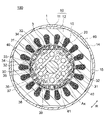
- FIG. 11 is a diagram showing the flow of magnetic flux in the stator core 10 and the rotor core 30 during magnetization by the magnetizing device 6 of Comparative Example 2, and is based on two-dimensional magnetic field analysis. A region where the magnetic flux is concentrated has a higher magnetic flux density. Magnetic saturation occurs in a region of high magnetic flux density. When magnetic saturation occurs, the dielectric constant of the electrical steel sheet decreases, making it difficult for magnetic flux to pass through.
- the magnetizing current that flows through the windings 20 when the permanent magnets 40 are magnetized is, for example, several kA, and is larger than the current that flows through the windings 20 when the electric motor 100 is driven. As a result, magnetic saturation becomes remarkable, and the magnetizing magnetic flux becomes difficult to flow. As a result, the magnetizing current required for magnetization increases.
- the Lorentz force acting between the windings 20 increases as described with reference to FIGS. 8(A) and (B). Since the windings 20 of the stator 1 are thinner and weaker than the windings 92 (FIG. 9A) of the magnetizing yoke 90, the windings 20 are easily damaged when the Lorentz force acts momentarily.
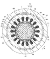
- FIG. 12 is a diagram showing the flow of magnetic flux in the stator core 10 and the rotor core 30 during magnetization by the magnetizing device 5 of Embodiment 1, and is based on two-dimensional magnetic field analysis.
- the outer yoke 50 is arranged on the outer peripheral side of the stator core 10 with the compressor shell 80 interposed therebetween.
- the magnetic flux generated by the magnetizing magnetic field also flows through the outer yoke 50 via the compressor shell 80 made of a magnetic material.
- the outer yoke 50 forms part of the magnetic path. Therefore, the magnetic path of the magnetizing magnetic flux can be expanded, and the occurrence of magnetic saturation in the stator core 10 can be suppressed.
- the magnetizing magnetic flux can be efficiently guided to the permanent magnet 40. As a result, less magnetizing current is required to obtain the same magnetic force. Also, the same magnetizing current can magnetize the permanent magnet 40 having a higher magnetic force.
- FIG. 13 is a graph showing the relationship between magnetomotive force and magnetization ratio for each of Embodiment 1 and Comparative Example 2.
- the magnetomotive force [kA ⁇ T] is the product of the current [kA] flowing through the winding 20 and the number of turns [T] of the winding 20 .
- the magnetization rate [%] indicates the degree of magnetization when complete magnetization is taken as 100%.
- Embodiment 1 compared to Comparative Example 2, the same magnetization rate can be obtained with a smaller magnetomotive force (that is, a smaller magnetizing current).
- the magnetomotive force required to obtain a magnetization ratio of 99.5% is 65 [kA ⁇ T] in Comparative Example 2, whereas it is 57.9 [kA ⁇ T] in Embodiment 1.
- the magnetizing current of the first embodiment is reduced by 10.9% as compared with the magnetizing current of the second comparative example.
- the Lorentz force is proportional to the square of the magnetizing current.
- the outer yoke 50 forms part of the magnetic path of the magnetizing magnetic flux, there is no need to widen the magnetic path inside the stator core 10 . Therefore, it is not necessary to make the slot 13 small, so that the necessary effective cross-sectional area of the winding 20 can be secured. As a result, it is possible to prevent the above-described decrease in motor efficiency.
- the permanent magnet 40 can be magnetized while the electric motor 100 is incorporated in the compressor 8, the electric motor 100 can be magnetized as in the case of using the magnetizing yoke 90 (FIG. 9A). 100 assemblability does not deteriorate.
- the outer yoke 50 is attached to the compressor shell 80 to expand the magnetic path of the magnetized magnetic flux when the permanent magnet 40 is magnetized, and is removed from the compressor shell 80 thereafter. Therefore, the compressor shell 80 does not interfere with peripheral parts such as refrigerant pipes.
- the outer yoke 50 is not wound with a winding, so that the outer yoke 50 can be easily attached to and removed from the compressor shell 80. can.
- Embodiment 1 the outer peripheral yoke 50 made of a magnetic material is detachably attached to the outside of the compressor shell 80 . It is possible to suppress the occurrence of magnetic saturation. As a result, less magnetizing current is required to magnetize the permanent magnet 40, and damage to the winding 20 can be suppressed. That is, the reliability of electric motor 100 can be improved.
- the magnetizing current is small, the capacity of the capacitor 64 of the power supply device 60 can be reduced, and the manufacturing cost of the magnetizing device 5 can be reduced. Further, since the outer yoke 50 is removed from the compressor shell 80 after the permanent magnet 40 is magnetized, it does not interfere with peripheral parts such as refrigerant pipes.
- the outer yoke 50 is composed of a laminate of magnetic steel sheets, it is possible to suppress the generation of eddy current when the magnetizing magnetic flux flows through the outer yoke 50 . By suppressing the generation of eddy currents, the heat generation of the outer yoke 50 can be suppressed, and the deterioration of the performance of the magnetizing device 5 can be suppressed.
- stator core 10 since the axial length of the outer yoke 50 is equal to or longer than the axial length of the stator core 10 , magnetizing magnetic flux easily flows to the outer yoke 50 from the entire axial direction of the stator core 10 . Therefore, the occurrence of magnetic saturation in stator core 10 can be more effectively suppressed.
- FIG. 14A is a side view showing the compressor 8 and the outer yoke 50 according to the second embodiment, showing only the outer yoke 50 in cross section.
- FIG. 14B is a cross-sectional view showing the compressor 8 of Embodiment 2, in which the outer yoke 50 is indicated by broken lines.
- the compressor shell 80 of the compressor 8 is formed with a convex portion 86 as a positioning portion for positioning the outer peripheral yoke 50 .
- Protrusions 86 axially position outer yoke 50 and stator core 10 by coming into contact with the lower surface of outer yoke 50 .
- the configuration of the outer yoke 50 is the same as that of the outer yoke 50 of the first embodiment.
- the protrusion 86 may be a protrusion that contacts the lower surface of the outer yoke 50. Just do it. Further, the outer peripheral yoke 50 may be supported from below by the convex portion 86 .
- a plurality of projections 86 may be provided on the outer peripheral surface of the compressor shell 80 at regular intervals in the circumferential direction.
- four protrusions 86 are provided, but the number of protrusions 86 may be one or more.
- the convex portion 86 may be formed in an annular shape so as to surround the compressor shell 80 .
- the work of attaching the outer yoke 50 to the compressor 8 is simplified by providing the convex portion 86 as a positioning portion on the compressor shell 80. become.
- Embodiment 2 is the same as Embodiment 1 except that the compressor shell 80 of the compressor 8 is provided with a convex portion 86 .
- the outer yoke 50 is positioned by the convex portion 86 of the compressor shell 80, the operation of attaching the outer yoke 50 to the compressor 8 is simplified, and the magnetization process is simplified. it gets easier.
- FIG. 15(A) is a perspective view showing the compressor 8 and the outer yoke 50A according to the third embodiment
- FIG. 15(B) is a partially cross-sectional perspective view showing the compressor 8 and the outer yoke 50A according to the third embodiment. It is a diagram. While the outer yoke 50 of the first embodiment is integrally constructed, the outer yoke 50A of the third embodiment is constructed by combining two divided yoke portions 71 and 72. As shown in FIG.
- FIG. 16(A) is a cross-sectional view showing the compressor 8 and the outer yoke 50A.
- Both of the divided yoke portions 71 and 72 are formed in a semi-annular shape centered on the axis Ax.
- the divided yoke portion 71 has a convex portion 71A at one end in the circumferential direction and a concave portion 71B at the other end.
- the divided yoke portion 72 has a convex portion 72A at one end in the circumferential direction and a concave portion 72B at the other end.
- the protrusion 71A of the split yoke portion 71 and the recess 72B of the split yoke portion 72 are engaged with each other, and the recess 71B of the split yoke portion 71 and the protrusion 72A of the split yoke portion 72 are engaged.
- the split yoke portions 71 and 72 are combined to form the outer yoke 50A.
- the convex portions 71A, 72A and the concave portions 71B, 72B constitute engaging portions.
- the split yoke portions 71 and 72 are attached to the compressor shell 80 from both sides, It can be an outer yoke 50A. Therefore, the outer yoke 50 ⁇ /b>A can be attached to the compressor shell 80 without interfering with the pipes 81 , 82 , 83 of the compressor shell 80 .
- the outer yoke 50A when the outer yoke 50A is wound with a winding such as the magnetizing outer yoke of Patent Document 1, the winding becomes an obstacle and cannot be divided into a plurality of divided yoke portions. Since no winding is wound around the outer yoke 50A here, the outer yoke 50A can be composed of a plurality of divided yoke portions 71 and 72. As shown in FIG.
- outer yoke 50A is configured by combining two divided yoke portions 71 and 72 here, three or more divided yoke portions may be combined.
- FIG. 16B shows an example in which four divided yoke portions 71, 72, 73, 74 are combined to form an outer yoke 50A.
- All of the divided yoke portions 71, 72, 73, and 74 shown in FIG. 16(B) extend in the circumferential direction within a range of 90 degrees around the axis Ax. Also, the projection 71A of the split yoke portion 71 engages the recess 72B of the split yoke portion 72, and the projection 72A of the split yoke portion 72 engages the recess 73B of the split yoke portion 73. As shown in FIG.
- the projection 73A of the split yoke portion 73 engages the recess 74B of the split yoke portion 74
- the projection 74A of the split yoke portion 74 engages the recess 71B of the split yoke portion 71. As shown in FIG.
- Embodiment 3 is the same as Embodiment 1 except that the outer yoke 50A is composed of a combination of a plurality of divided yoke portions 71 and 72. Also, as in the second embodiment, the compressor shell 80 may be provided with a convex portion 86 as a positioning portion.
- the outer yoke 50A is configured by combining a plurality of divided yoke portions 71 and 72 (or divided yoke portions 71 to 74). , 83 are attached, the outer yoke 50A can be easily attached to the compressor shell 80 without interfering with these pipes 81, 82, 83.
- FIG. 17A is a sectional view showing compressor 8 and outer yoke 50B of the fourth embodiment. While the outer yoke 50 of the first embodiment has an annular shape, the outer yoke 50B of the fourth embodiment is C-shaped. That is, the outer yoke 50B of the fourth embodiment has the notch 53 at one place in the circumferential direction.
- the outer yoke 50B has two end faces 53a that define both ends of the notch 53 in the circumferential direction.
- the notch portion 53 of the outer yoke 50B has an angle (referred to as a notch angle) A about the axis Ax.
- the notch angle A is the angle between the two end faces 53a about the axis Ax.
- the notch angle A is 20 degrees. In the example shown in FIG. 17B, the notch angle A is 80 degrees.
- the notch portion 53 faces the D cut portion 15 of the stator core 10 with the compressor shell 80 interposed therebetween in the radial direction.
- the outer yoke 50B Since the outer yoke 50B has the notch 53, when attaching the outer yoke 50B to the compressor shell 80, it can be attached so that the notch 53 of the outer yoke 50B passes through the suction pipe 81. Therefore, the outer yoke 50B can be attached to the compressor shell 80 without interfering with the pipes 81, 82, 83 when all the pipes 81, 82, 83 are attached to the compressor shell 80.
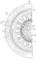
- FIG. 18 is a diagram showing the flow of magnetic flux in the stator core 10 and the rotor core 30 during magnetization in Embodiment 4, and is based on two-dimensional magnetic field analysis.
- the cutout angle A is 20 degrees here. Since the compressor shell 80 is not in contact with the D-cut portion 15 of the stator core 10 , less magnetizing magnetic flux flows through the portion of the compressor shell 80 facing the D-cut portion 15 .
- the notch 53 faces the D-cut portion 15 of the stator core 10 through the compressor shell 80, the influence of the notch 53 on the flow of magnetic flux can be minimized. That is, the effect of suppressing magnetic saturation similar to that of the annular outer yoke 50 can be obtained.
- FIG. 19 is a graph showing the relationship between the magnetomotive force and the magnetization ratio for the first and fourth embodiments and the second comparative example.
- the data of Embodiment 1 and Comparative Example 2 are the same as in FIG.
- the data of the fourth embodiment are data in the case where the cutout portion 53 faces the D cut portion 15 of the stator core 10 through the compressor shell 80 as shown in FIG. 18 and the cutout angle A is 20 degrees. is.
- the first embodiment and the fourth embodiment can obtain the same magnetization rate with the same magnetomotive force (that is, the same magnetizing current).
- the magnetomotive force required to obtain a magnetization rate of 99.5% is 65 [kA ⁇ T] in Comparative Example 2 described above, but is 57.9 [kA ⁇ T] in Embodiment 1. In the fourth embodiment, it is 58.1 [kA ⁇ T].
- the magnetizing current in the first embodiment is 10.9% lower than the magnetizing current in the comparative example 2, and the magnetizing current in the fourth embodiment is 10.6%. Decrease.
- FIG. 20 is a graph showing the relationship between the notch angle A [degrees] of the outer yoke 50B and the magnetomotive force [kA ⁇ T] required to obtain the magnetization ratio of the permanent magnet 40 of 99.5%.
- the notch portion 53 faces the D-cut portion 15 of the stator core 10 via the compressor shell 80 as shown in FIG. 18, and the notch angle A is varied from 0 degrees to 80 degrees.
- the notch angle A is 20 degrees or less, the magnetizing current required to obtain a magnetization rate of 99.5% is small, and the increase rate of the magnetizing current with respect to the increase in the notch angle A is also small. .
- the cutout angle A exceeds 20 degrees, the rate of increase in the magnetizing current with respect to the increase in the cutout angle A increases. Therefore, it is desirable that the notch angle A is 20 degrees or less.
- the lower limit of the notch angle A is the angle at which one pipe (for example, the suction pipe 81) can pass through the notch 53 in the axial direction.
- FIG. 21A is a diagram showing a state in which the circumferential center of cutout portion 53 of outer yoke 50B coincides with the circumferential center of D-cut portion 15 of stator core 10 .
- FIG. 21(B) is a diagram showing a state in which the circumferential center of notch 53 of outer yoke 50B is circumferentially displaced from the circumferential center of D-cut portion 15 of stator core 10 .
- a straight line passing through the axis Ax and the center of the D-cut portion 15 of the stator core 10 in the circumferential direction is defined as a first straight line T1.
- a straight line passing through the axis Ax and the center of the notch 53 of the outer yoke 50B in the circumferential direction is defined as a second straight line T2.
- the angle formed by the first straight line T1 and the second straight line T2 is referred to as the circumferential position of the cutout portion 53 or the cutout position.
- FIG. 22 is a graph showing the relationship between the circumferential position [degrees] of the notch 53 and the magnetomotive force [kA ⁇ T] required to obtain the magnetization ratio of the permanent magnet 40 of 99.5%.
- the circumferential position of the notch 53 has less influence on the magnetizing current, so the circumferential position of the notch 53 may exceed 20 degrees.
- Embodiment 4 is the same as Embodiment 1 except that the outer yoke 50B is C-shaped. Further, as described in the second embodiment, the compressor shell 80 may be provided with the convex portion 86 as a positioning portion. Further, as described in the third embodiment, the C-shaped outer yoke 50B may be configured by combining a plurality of divided yoke portions.
- the outer yoke 50B since the outer yoke 50B has the cutout portion 53, even when the pipes 81, 82, 83 are all attached to the compressor shell 80, these pipes 81, 82 , 83, the outer yoke 50B can be easily attached to the compressor shell 80.
- the notch angle A of the notch portion 53 is 20 degrees or less, the magnetizing current required to obtain a constant magnetization rate can be reduced, and damage to the winding 20 can be suppressed.
- the circumferential position of the notch portion 53 with respect to the D-cut portion 15 of the stator core 10 is 20 degrees or less, the magnetizing current required to obtain a constant magnetization rate is reduced, and damage to the winding 20 is suppressed. can do.
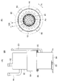
- FIG. 23 shows a demagnetizing device 5B for demagnetizing the electric motor 100 incorporated in the used compressor 8.
- the demagnetizing device 5B has an outer yoke 50 attached to the compressor 8 and a power supply device 60 .
- the configurations of the outer yoke 50 and the power supply device 60 are as described in the first embodiment. Terminals 60a and 60b of power supply device 60 are connected to windings 20 of electric motor 100 via wires L1 and L2.
- the compressor 8 is as described in Embodiment 1, except that it has been used.
- FIG. 24 shows the demagnetizing current flowing from the power supply 60 to the windings 20 of the electric motor 100 .
- the demagnetizing current has a waveform with gradually decreasing amplitude. As the demagnetizing current flows through the winding 20, the magnetic force of the permanent magnet 40 is gradually weakened and demagnetized. After the permanent magnet 40 is demagnetized, the compressor 8 is dismantled, the electric motor 100 is dismantled, and reusable parts are reused.
- the demagnetizing current has a large peak current at the start of application, it is possible to suppress the occurrence of magnetic saturation in the stator core 10 by causing part of the demagnetizing magnetic flux to flow through the outer yoke 50 .
- the demagnetizing current required for demagnetizing can be reduced, the capacitance of the capacitor 64 can be reduced, and the manufacturing cost of the power supply device 60 can be reduced.
- outer yokes 50A and 50B described in the third and fourth embodiments may be used for the demagnetizing device 5B shown in FIG.
- a positioning portion may be provided on the outer circumference of the compressor shell 80 .
- FIG. 25 is a cross-sectional view showing compressor 300.
- Compressor 300 is a scroll compressor here, but is not limited to this.
- the compressor 300 includes a compressor shell 307, a compression mechanism 305 disposed within the compressor shell 307, an electric motor 100 that drives the compression mechanism 305, a shaft 41 that connects the compression mechanism 305 and the electric motor 100, and a subframe 308 that supports the lower end of the shaft 41 .
- the compression mechanism 305 includes a fixed scroll 301 having a spiral portion, an orbiting scroll 302 having a spiral portion forming a compression chamber between the spiral portion of the fixed scroll 301 and a compliance frame 303 holding the upper end of the shaft 41 . and a guide frame 304 fixed to the compressor shell 307 to hold the compliance frame 303 .
- a suction pipe 310 passing through the compressor shell 307 is press-fitted into the fixed scroll 301 .
- the compressor shell 307 is provided with a discharge pipe 311 for discharging high-pressure refrigerant gas discharged from the fixed scroll 301 to the outside.
- the discharge pipe 311 communicates with an opening (not shown) provided between the compression mechanism 305 of the compressor shell 307 and the electric motor 100 .
- the electric motor 100 is fixed to the compressor shell 307 by fitting the stator 1 into the compressor shell 307 .
- the configuration of electric motor 100 is as described above.
- a glass terminal 309 that supplies electric power to the electric motor 100 is fixed to the compressor shell 307 by welding.
- Wirings L1 and L2 shown in FIG. 3 are connected to the glass terminal 309 .
- the compressor shell 307 corresponds to the compressor shell 80 (FIG. 6(A)) described in the first embodiment.
- Suction pipe 310 and discharge pipe 311 correspond to suction pipe 81 and discharge pipe 82 (FIG. 6A) described in the first embodiment, respectively.
- Piping corresponding to the oil pipe 83 is omitted in FIG.
- Piping corresponding to the oil pipe 83 is omitted in FIG.
- the electric motor 100 of the compressor 300 has high reliability due to damage suppression of the windings 20 . Therefore, the reliability of compressor 300 can be improved.
- FIG. 26 is a diagram showing a refrigeration cycle device 400.
- the refrigeration cycle device 400 is, for example, an air conditioner, but is not limited to this.
- a refrigeration cycle device 400 shown in FIG. 26 includes a compressor 401, a condenser 402 that condenses the refrigerant, a decompression device 403 that decompresses the refrigerant, and an evaporator 404 that evaporates the refrigerant.
- Compressor 401 , condenser 402 and decompression device 403 are provided in indoor unit 410
- evaporator 404 is provided in outdoor unit 420 .
- the compressor 401, the condenser 402, the decompression device 403 and the evaporator 404 are connected by a refrigerant pipe 407 to form a refrigerant circuit.
- Compressor 401 is composed of compressor 300 shown in FIG.
- the refrigerating cycle device 400 also includes an outdoor fan 405 facing the condenser 402 and an indoor fan 406 facing the evaporator 404 .
- the operation of the refrigeration cycle device 400 is as follows.
- the compressor 401 compresses the sucked refrigerant and sends it out as a high-temperature, high-pressure refrigerant gas.
- the condenser 402 exchanges heat between the refrigerant sent from the compressor 401 and the outdoor air sent by the outdoor fan 405, condenses the refrigerant, and sends it out as a liquid refrigerant.
- the decompression device 403 expands the liquid refrigerant sent from the condenser 402 and sends it out as a low-temperature, low-pressure liquid refrigerant.
- the evaporator 404 exchanges heat between the low-temperature, low-pressure liquid refrigerant sent out from the decompression device 403 and the indoor air, evaporates (vaporizes) the refrigerant, and sends it out as refrigerant gas.
- the air from which heat has been removed by the evaporator 404 is supplied by the indoor blower 406 into the room, which is the space to be air-conditioned.
- the electric motor 100 described in each embodiment can be applied to the compressor 401 of the refrigeration cycle device 400 . Since the electric motor 100 has high reliability due to the suppression of damage to the windings 20, the reliability of the refrigeration cycle device 400 can be improved.
Landscapes
- Engineering & Computer Science (AREA)
- Power Engineering (AREA)
- Manufacturing & Machinery (AREA)
- Permanent Field Magnets Of Synchronous Machinery (AREA)
- Compressor (AREA)
- Applications Or Details Of Rotary Compressors (AREA)
- Iron Core Of Rotating Electric Machines (AREA)
Priority Applications (4)
| Application Number | Priority Date | Filing Date | Title |
|---|---|---|---|
| PCT/JP2021/001666 WO2022157827A1 (ja) | 2021-01-19 | 2021-01-19 | 着磁装置、着磁方法、ロータ、電動機、圧縮機および冷凍サイクル装置 |
| US18/255,121 US20240030791A1 (en) | 2021-01-19 | 2021-01-19 | Magnetizing apparatus, magnetizing method, rotor, motor, compressor, and refrigeration cycle apparatus |
| CN202180084795.7A CN116615855A (zh) | 2021-01-19 | 2021-01-19 | 磁化装置、磁化方法、转子、电动机、压缩机和制冷循环装置 |
| JP2022576252A JP7374352B2 (ja) | 2021-01-19 | 2021-01-19 | 着磁装置、着磁方法、ロータ、電動機、圧縮機および冷凍サイクル装置 |
Applications Claiming Priority (1)
| Application Number | Priority Date | Filing Date | Title |
|---|---|---|---|
| PCT/JP2021/001666 WO2022157827A1 (ja) | 2021-01-19 | 2021-01-19 | 着磁装置、着磁方法、ロータ、電動機、圧縮機および冷凍サイクル装置 |
Publications (1)
| Publication Number | Publication Date |
|---|---|
| WO2022157827A1 true WO2022157827A1 (ja) | 2022-07-28 |
Family
ID=82549599
Family Applications (1)
| Application Number | Title | Priority Date | Filing Date |
|---|---|---|---|
| PCT/JP2021/001666 Ceased WO2022157827A1 (ja) | 2021-01-19 | 2021-01-19 | 着磁装置、着磁方法、ロータ、電動機、圧縮機および冷凍サイクル装置 |
Country Status (4)
| Country | Link |
|---|---|
| US (1) | US20240030791A1 (https=) |
| JP (1) | JP7374352B2 (https=) |
| CN (1) | CN116615855A (https=) |
| WO (1) | WO2022157827A1 (https=) |
Cited By (1)
| Publication number | Priority date | Publication date | Assignee | Title |
|---|---|---|---|---|
| JP2025186043A (ja) * | 2024-06-11 | 2025-12-23 | 株式会社明電舎 | ロータコア、ロータ、回転電機及び車両駆動用装置 |
Families Citing this family (1)
| Publication number | Priority date | Publication date | Assignee | Title |
|---|---|---|---|---|
| WO2025158644A1 (ja) * | 2024-01-26 | 2025-07-31 | 三菱電機株式会社 | 電動機、圧縮機および冷凍サイクル装置 |
Citations (3)
| Publication number | Priority date | Publication date | Assignee | Title |
|---|---|---|---|---|
| JPH11252874A (ja) * | 1998-03-05 | 1999-09-17 | Daikin Ind Ltd | 永久磁石型電動機の着磁方法および着磁用部材 |
| JP2010193587A (ja) * | 2009-02-17 | 2010-09-02 | Yaskawa Electric Corp | ロータ用磁石着磁装置およびモータ |
| JP2019022449A (ja) * | 2013-11-08 | 2019-02-07 | 三星電子株式会社Samsung Electronics Co.,Ltd. | モータ及びその製造方法 |
-
2021
- 2021-01-19 WO PCT/JP2021/001666 patent/WO2022157827A1/ja not_active Ceased
- 2021-01-19 JP JP2022576252A patent/JP7374352B2/ja active Active
- 2021-01-19 CN CN202180084795.7A patent/CN116615855A/zh not_active Withdrawn
- 2021-01-19 US US18/255,121 patent/US20240030791A1/en not_active Abandoned
Patent Citations (3)
| Publication number | Priority date | Publication date | Assignee | Title |
|---|---|---|---|---|
| JPH11252874A (ja) * | 1998-03-05 | 1999-09-17 | Daikin Ind Ltd | 永久磁石型電動機の着磁方法および着磁用部材 |
| JP2010193587A (ja) * | 2009-02-17 | 2010-09-02 | Yaskawa Electric Corp | ロータ用磁石着磁装置およびモータ |
| JP2019022449A (ja) * | 2013-11-08 | 2019-02-07 | 三星電子株式会社Samsung Electronics Co.,Ltd. | モータ及びその製造方法 |
Cited By (2)
| Publication number | Priority date | Publication date | Assignee | Title |
|---|---|---|---|---|
| JP2025186043A (ja) * | 2024-06-11 | 2025-12-23 | 株式会社明電舎 | ロータコア、ロータ、回転電機及び車両駆動用装置 |
| JP7810203B2 (ja) | 2024-06-11 | 2026-02-03 | 株式会社明電舎 | ロータコア、ロータ、回転電機及び車両駆動用装置 |
Also Published As
| Publication number | Publication date |
|---|---|
| US20240030791A1 (en) | 2024-01-25 |
| CN116615855A (zh) | 2023-08-18 |
| JPWO2022157827A1 (https=) | 2022-07-28 |
| JP7374352B2 (ja) | 2023-11-06 |
Similar Documents
| Publication | Publication Date | Title |
|---|---|---|
| JP6053910B2 (ja) | 永久磁石埋込型電動機、圧縮機、および冷凍空調装置 | |
| JP6537623B2 (ja) | ステータ、電動機、圧縮機、及び冷凍空調装置 | |
| WO2020021692A1 (ja) | 電動機、圧縮機および空気調和装置 | |
| JP4815686B2 (ja) | 電動機の製造方法 | |
| JP7038827B2 (ja) | ステータ、電動機、圧縮機および空気調和装置 | |
| GB2555354A (en) | Permanent Magnet-Embedded Motor, Compressor, and Refrigerating and Air Conditioning Apparatus | |
| JP2023168510A (ja) | 電動機、圧縮機、送風機、及び冷凍空調装置 | |
| JP7105999B2 (ja) | 電動機、圧縮機、空気調和装置および電動機の製造方法 | |
| WO2018029818A1 (ja) | 電動機、圧縮機、冷凍空調装置および電動機の製造方法 | |
| WO2019215865A1 (ja) | ロータ、電動機、圧縮機および空気調和装置 | |
| JP7374352B2 (ja) | 着磁装置、着磁方法、ロータ、電動機、圧縮機および冷凍サイクル装置 | |
| JP7154373B2 (ja) | 電動機、圧縮機、及び空気調和機 | |
| JP7130131B2 (ja) | 着磁用リング、着磁方法、着磁装置、ロータ、電動機、圧縮機および空気調和装置 | |
| CN117044073A (zh) | 马达、压缩机和制冷循环装置 | |
| JP7258140B2 (ja) | 回転子、電動機、圧縮機、及び空気調和機 | |
| WO2023181238A1 (ja) | 固定子、電動機、圧縮機および冷凍サイクル装置 | |
| JP7486911B2 (ja) | 電動機、圧縮機、冷凍サイクル装置、着磁方法および着磁装置 | |
| WO2023119455A1 (ja) | 着磁方法、電動機、圧縮機および冷凍サイクル装置 | |
| WO2024150393A1 (ja) | 着磁方法、電動機、圧縮機および冷凍サイクル装置 | |
| US20230198328A1 (en) | Stator, motor, compressor, refrigeration cycle apparatus, and air conditioner | |
| WO2024166161A1 (ja) | 回転子、電動機、圧縮機および冷凍サイクル装置 | |
| WO2023037438A1 (ja) | ロータ、モータ、圧縮機および冷凍サイクル装置 |
Legal Events
| Date | Code | Title | Description |
|---|---|---|---|
| 121 | Ep: the epo has been informed by wipo that ep was designated in this application |
Ref document number: 21920944 Country of ref document: EP Kind code of ref document: A1 |
|
| ENP | Entry into the national phase |
Ref document number: 2022576252 Country of ref document: JP Kind code of ref document: A |
|
| WWE | Wipo information: entry into national phase |
Ref document number: 18255121 Country of ref document: US |
|
| WWE | Wipo information: entry into national phase |
Ref document number: 202180084795.7 Country of ref document: CN |
|
| NENP | Non-entry into the national phase |
Ref country code: DE |
|
| 122 | Ep: pct application non-entry in european phase |
Ref document number: 21920944 Country of ref document: EP Kind code of ref document: A1 |