WO2022153912A1 - スタイレットおよびカテーテル組立体 - Google Patents
スタイレットおよびカテーテル組立体 Download PDFInfo
- Publication number
- WO2022153912A1 WO2022153912A1 PCT/JP2022/000180 JP2022000180W WO2022153912A1 WO 2022153912 A1 WO2022153912 A1 WO 2022153912A1 JP 2022000180 W JP2022000180 W JP 2022000180W WO 2022153912 A1 WO2022153912 A1 WO 2022153912A1
- Authority
- WO
- WIPO (PCT)
- Prior art keywords
- catheter
- layer tube
- stylet
- tip
- blood
- Prior art date
- Legal status (The legal status is an assumption and is not a legal conclusion. Google has not performed a legal analysis and makes no representation as to the accuracy of the status listed.)
- Ceased
Links
Images




Classifications
-
- A—HUMAN NECESSITIES
- A61—MEDICAL OR VETERINARY SCIENCE; HYGIENE
- A61M—DEVICES FOR INTRODUCING MEDIA INTO, OR ONTO, THE BODY; DEVICES FOR TRANSDUCING BODY MEDIA OR FOR TAKING MEDIA FROM THE BODY; DEVICES FOR PRODUCING OR ENDING SLEEP OR STUPOR
- A61M25/00—Catheters; Hollow probes
- A61M25/01—Introducing, guiding, advancing, emplacing or holding catheters
- A61M25/0102—Insertion or introduction using an inner stiffening member, e.g. stylet or push-rod
-
- A—HUMAN NECESSITIES
- A61—MEDICAL OR VETERINARY SCIENCE; HYGIENE
- A61M—DEVICES FOR INTRODUCING MEDIA INTO, OR ONTO, THE BODY; DEVICES FOR TRANSDUCING BODY MEDIA OR FOR TAKING MEDIA FROM THE BODY; DEVICES FOR PRODUCING OR ENDING SLEEP OR STUPOR
- A61M1/00—Suction or pumping devices for medical purposes; Devices for carrying-off, for treatment of, or for carrying-over, body-liquids; Drainage systems
- A61M1/36—Other treatment of blood in a by-pass of the natural circulatory system, e.g. temperature adaptation, irradiation ; Extra-corporeal blood circuits
- A61M1/3621—Extra-corporeal blood circuits
- A61M1/3653—Interfaces between patient blood circulation and extra-corporal blood circuit
- A61M1/3659—Cannulae pertaining to extracorporeal circulation
-
- A—HUMAN NECESSITIES
- A61—MEDICAL OR VETERINARY SCIENCE; HYGIENE
- A61M—DEVICES FOR INTRODUCING MEDIA INTO, OR ONTO, THE BODY; DEVICES FOR TRANSDUCING BODY MEDIA OR FOR TAKING MEDIA FROM THE BODY; DEVICES FOR PRODUCING OR ENDING SLEEP OR STUPOR
- A61M1/00—Suction or pumping devices for medical purposes; Devices for carrying-off, for treatment of, or for carrying-over, body-liquids; Drainage systems
- A61M1/36—Other treatment of blood in a by-pass of the natural circulatory system, e.g. temperature adaptation, irradiation ; Extra-corporeal blood circuits
- A61M1/3621—Extra-corporeal blood circuits
- A61M1/3666—Cardiac or cardiopulmonary bypass, e.g. heart-lung machines
-
- A—HUMAN NECESSITIES
- A61—MEDICAL OR VETERINARY SCIENCE; HYGIENE
- A61M—DEVICES FOR INTRODUCING MEDIA INTO, OR ONTO, THE BODY; DEVICES FOR TRANSDUCING BODY MEDIA OR FOR TAKING MEDIA FROM THE BODY; DEVICES FOR PRODUCING OR ENDING SLEEP OR STUPOR
- A61M25/00—Catheters; Hollow probes
-
- A—HUMAN NECESSITIES
- A61—MEDICAL OR VETERINARY SCIENCE; HYGIENE
- A61M—DEVICES FOR INTRODUCING MEDIA INTO, OR ONTO, THE BODY; DEVICES FOR TRANSDUCING BODY MEDIA OR FOR TAKING MEDIA FROM THE BODY; DEVICES FOR PRODUCING OR ENDING SLEEP OR STUPOR
- A61M25/00—Catheters; Hollow probes
- A61M25/0021—Catheters; Hollow probes characterised by the form of the tubing
- A61M25/0023—Catheters; Hollow probes characterised by the form of the tubing by the form of the lumen, e.g. cross-section, variable diameter
- A61M25/0026—Multi-lumen catheters with stationary elements
- A61M25/0028—Multi-lumen catheters with stationary elements characterized by features relating to at least one lumen located at the proximal part of the catheter, e.g. alterations in lumen shape or valves
-
- A—HUMAN NECESSITIES
- A61—MEDICAL OR VETERINARY SCIENCE; HYGIENE
- A61M—DEVICES FOR INTRODUCING MEDIA INTO, OR ONTO, THE BODY; DEVICES FOR TRANSDUCING BODY MEDIA OR FOR TAKING MEDIA FROM THE BODY; DEVICES FOR PRODUCING OR ENDING SLEEP OR STUPOR
- A61M25/00—Catheters; Hollow probes
- A61M25/0043—Catheters; Hollow probes characterised by structural features
-
- A—HUMAN NECESSITIES
- A61—MEDICAL OR VETERINARY SCIENCE; HYGIENE
- A61M—DEVICES FOR INTRODUCING MEDIA INTO, OR ONTO, THE BODY; DEVICES FOR TRANSDUCING BODY MEDIA OR FOR TAKING MEDIA FROM THE BODY; DEVICES FOR PRODUCING OR ENDING SLEEP OR STUPOR
- A61M25/00—Catheters; Hollow probes
- A61M25/0043—Catheters; Hollow probes characterised by structural features
- A61M25/0045—Catheters; Hollow probes characterised by structural features multi-layered, e.g. coated
-
- A—HUMAN NECESSITIES
- A61—MEDICAL OR VETERINARY SCIENCE; HYGIENE
- A61M—DEVICES FOR INTRODUCING MEDIA INTO, OR ONTO, THE BODY; DEVICES FOR TRANSDUCING BODY MEDIA OR FOR TAKING MEDIA FROM THE BODY; DEVICES FOR PRODUCING OR ENDING SLEEP OR STUPOR
- A61M25/00—Catheters; Hollow probes
- A61M25/0043—Catheters; Hollow probes characterised by structural features
- A61M2025/0063—Catheters; Hollow probes characterised by structural features having means, e.g. stylets, mandrils, rods or wires to reinforce or adjust temporarily the stiffness, column strength or pushability of catheters which are already inserted into the human body
Definitions
- the present invention relates to a stylet and catheter assembly.
- PCPS percutaneous cardioplemonary support
- the extracorporeal circulation device is equipped with an extracorporeal circulation circuit composed of a centrifugal pump, an artificial lung, a blood removal channel, a blood supply channel, etc., and exchanges gas with the blood that has been removed to send blood to the blood supply channel.
- a high-performance cannula disclosed in Patent Document 1 can be used for the blood removal path and blood supply path of such an extracorporeal circulation circuit.
- the high-performance cannula (catheter assembly) disclosed in Patent Document 1 is inserted into a living body with a mandrel (stylet) inserted into the cannula body (catheter).
- Patent Document 2 discloses a catheter in which resins having different materials and hardness are joined to each other to provide flexibility on the distal end side and maintain hardness on the proximal end side. There is.
- Patent Document 2 When the catheter disclosed in Patent Document 2 is used as a stylet, it is configured by joining resins of different materials, so that it cannot be joined favorably depending on the compatibility between the materials of different materials, and at the joint, it cannot be joined. There is a risk of kink or damage.
- the inner peripheral surface of the outer layer tube is designated from the tip of the outer layer tube. It is conceivable that the inner layer tube is arranged at a position separated from the base end side by the distance of. However, when the stylet having this configuration is inserted into the tube and inserted into the living body along the guide wire, the guide wire collides with the step caused by the wall thickness of the inner layer tube, which makes the catheter assembly suitable. It may not be possible to insert it.
- the present invention has been made to solve the above problems, and while preventing the occurrence of kink and breakage, the tip side is made flexible to maintain the hardness of the base end side at a desired hardness, and a guide is provided. It is an object of the present invention to provide a stylet and a catheter assembly into which a catheter assembly can be suitably inserted along a wire.
- the stylet that achieves the above purpose is a stylet that can be inserted into a catheter equipped with a lumen capable of circulating blood.
- the stylet has an outer layer tube extending in the axial direction, an inner layer tube arranged on the inner circumference of the outer layer tube, having a hollow shape, and being harder than the outer layer tube.
- the inner layer tube has a reduced diameter portion whose diameter is reduced toward the proximal end side in the axial direction on the inner peripheral surface of the tip end portion of the inner layer tube.
- the catheter assembly that achieves the above object has the above stylet and a catheter configured so that the stylet can be inserted.
- the stylet and catheter assembly constructed as described above, it has an outer layer tube extending in the axial direction and an inner layer tube arranged on the inner circumference of the outer layer tube and harder than the outer layer tube. While preventing the occurrence of breakage, the tip side can be made flexible and the hardness on the base end side can be maintained at a desired hardness. Further, since the inner layer tube has a reduced diameter portion, when the catheter assembly is inserted into the living body along the reduced diameter portion, the guide wire can pass through the lumen of the inner layer tube along the reduced diameter portion.
- the tip side can be made flexible to maintain the hardness on the base end side at a desired hardness, and the catheter assembly can be suitably inserted along the guide wire.
- Stylet and catheter assemblies can be provided.
- FIG. 1 It is a system diagram which shows an example of the extracorporeal circulation apparatus to which the percutaneous catheter which concerns on embodiment of this invention is applied. It is a side view which shows the state before inserting the stylet which concerns on this embodiment into a catheter. It is a side sectional view which shows the catheter. It is a side view which shows the state after inserting the stylet which concerns on this embodiment into a catheter. It is a figure for demonstrating the knitting angle of the 1st reinforcing body. It is a figure for demonstrating the knitting angle of the 2nd reinforcing body. It is the schematic sectional drawing which shows the structure of the stylet which concerns on this embodiment. It is a partially enlarged view of the part A of FIG. It is a figure corresponding to FIG.
- FIG. 1 when the percutaneous catheter according to the embodiment of the present invention is applied, when the patient's heart is weakened, the heart and lung functions are temporarily assisted / substituted until the heart function is restored.
- PCPS percutaneous cardiopulmonary support method
- the pump is operated to remove blood from the patient's vein (large vein), gas is exchanged in the blood by an artificial lung to oxygenate the blood, and then the blood is returned to the blood.
- a venous-arterial (Veno-Arterial, VA) procedure can be performed to return the patient's artery (aorta).
- VA venous-arterial
- the extracorporeal circulatory device 1 is a device that assists the heart and lungs.
- extracorporeal circulation the procedure of removing blood from a patient, performing a predetermined treatment outside the body, and then sending blood back into the patient's body.
- the extracorporeal circulatory device 1 has a circulation circuit for circulating blood.
- the circulation circuit includes an artificial lung 2, a centrifugal pump 3, a drive motor 4 which is a driving means for driving the centrifugal pump 3, a venous catheter (percutaneous catheter for blood removal) 5, and an arterial catheter (a percutaneous catheter for blood removal). It has a blood feeding catheter) 6 and a controller 10 as a control unit.
- the venous catheter (catheter for blood removal) 5 is inserted from the femoral vein, and the tip of the venous catheter 5 is placed in the right atrium via the inferior vena cava.
- the venous catheter 5 is connected to the centrifugal pump 3 via a blood removal tube (blood removal line) 11.
- the blood removal tube 11 is a conduit for sending blood.
- the arterial catheter (blood feeding catheter) 6 is inserted from the femoral artery.
- the centrifugal pump 3 removes blood from the blood removal tube 11 and passes blood through the artificial lung 2, and then the blood feeding tube (blood feeding line). Blood can be returned to patient P via 12.
- the artificial lung 2 is arranged between the centrifugal pump 3 and the blood feeding tube 12.
- the artificial lung 2 performs gas exchange (addition of oxygen and / or removal of carbon dioxide) to blood.
- the artificial lung 2 is, for example, a membrane type artificial lung, but a hollow fiber membrane type artificial lung is particularly preferably used.
- Oxygen gas is supplied from the oxygen gas supply unit 13 to the artificial lung 2 through the tube 14.
- the blood feeding tube 12 is a conduit connecting the artificial lung 2 and the arterial catheter 6.
- a highly transparent, elastically deformable and flexible synthetic resin tube such as a vinyl chloride resin or silicone rubber can be used.
- the liquid blood flows in the V1 direction, and in the blood feeding tube 12, the blood flows in the V2 direction.
- the ultrasonic bubble detection sensor 20 is arranged in the middle of the blood removal tube 11.
- the fast clamp 17 is arranged in the middle of the blood feeding tube 12.
- the ultrasonic bubble detection sensor 20 detects bubbles mixed in the circulation circuit due to an erroneous operation of the three-way stopcock 18 or damage to the tube during extracorporeal circulation.
- the ultrasonic bubble detection sensor 20 detects that there are bubbles in the blood sent into the blood removal tube 11
- the ultrasonic bubble detection sensor 20 sends a detection signal to the controller 10.
- the controller 10 notifies an alarm by an alarm, lowers the rotation speed of the centrifugal pump 3, or stops the centrifugal pump 3.
- the controller 10 commands the fast clamp 17 to immediately close the blood feeding tube 12 by the fast clamp 17. This prevents air bubbles from being sent into the patient P's body.
- the controller 10 controls the operation of the extracorporeal circulation device 1 to prevent air bubbles from entering the body of the patient P.
- a pressure sensor is provided on the tubes 11 (12, 19) of the circulation circuit of the extracorporeal circulation device 1.
- the pressure sensor can be, for example, either the mounting position A1 of the blood removal tube 11, the mounting position A2 of the blood feeding tube 12 of the circulation circuit, or the mounting position A3 of the connecting tube 19 connecting the centrifugal pump 3 and the artificial lung 2. Can be attached to one or all. Thereby, the pressure in the tube 11 (12, 19) can be measured by the pressure sensor when the extracorporeal circulation device 1 is performing extracorporeal circulation to the patient P.
- the mounting position of the pressure sensor is not limited to the mounting positions A1, A2, and A3, and can be mounted at any position in the circulation circuit.
- catheter 30 percutaneous catheter
- This catheter 30 is used as the venous side catheter (blood removal catheter) 5 of FIG.
- the configuration of the catheter 30 described below is an example, and the catheter into which the stylet 50 according to the present embodiment is inserted is not limited to the following configuration.
- the catheter 30 includes a catheter tube 31 having a first side hole 63 and a second side hole 46, a tip tip 41 having a through hole 47 arranged at the tip of the catheter tube 31, and a catheter tube 31. It has a clamp tube 34 arranged on the proximal end side of the catheter tube 31, a catheter connector 35 for connecting the catheter tube 31 and the clamp tube 34, and a lock connector 36.
- the side to be inserted into the living body is referred to as "tip” or “tip side”
- the hand side operated by the operator is referred to as "base end” or “base end side”.
- the tip portion means a certain range including the tip (leading edge) and its periphery
- the proximal end portion means a certain range including the proximal end (most proximal end) and its periphery.
- the catheter 30 has a lumen 30A penetrating from the tip end to the base end.
- the through hole 47 included in the tip tip 41, the first side hole 63 included in the catheter tube 31, and the second side hole 46 are arranged in different blood removal targets in the living body so that blood can be efficiently removed. Has been done.
- the stylet 50 shown in FIG. 2 When inserting the catheter 30 into the living body, the stylet 50 shown in FIG. 2 is used.
- the stylet 50 is inserted into the lumen 30A of the catheter 30, and the catheter 30 and the stylet 50 are inserted into the living body in a state of being integrated in advance.
- the structure in which the catheter 30 and the stylet 50 are integrated is referred to as a catheter assembly 7.
- the configuration of the catheter 30 is not limited to the following.
- the catheter tube 31 has an expansion portion 32 and a shaft portion 33 connected to the proximal end side of the expansion portion 32.
- the expansion portion 32 is configured to have higher elasticity than the shaft portion 33. Further, the expansion portion 32 is configured to have a larger outer diameter and inner diameter than the shaft portion 33.
- the length of the extension portion 32 and the shaft portion 33 is the length required for arranging the through hole 47 of the tip tip 41 and the first side hole 63 and the second side hole 46 of the catheter tube 31 in the desired blood removal target. It is composed of.
- the length of the extension portion 32 can be, for example, 20 to 40 cm, and the length of the shaft portion 33 can be, for example, 20 to 30 cm.
- the catheter 30 is inserted into the living body so that the through hole 47 of the tip tip 41 and the second side hole 46 of the catheter tube 31 are arranged in the right atrium and the first side hole 63 of the catheter tube 31 is arranged in the inferior vena cava. And detained.
- the dilation portion 32 is arranged in the inferior vena cava, which is a relatively large blood vessel, and the shaft portion 33 is relatively. It is placed in the femoral vein, which is a small blood vessel.
- the highly elastic expansion portion 32 extends in the axial direction and the outer diameter and inner diameter become smaller.
- the outer diameter of the expansion portion 32 is substantially the same as the outer diameter of the shaft portion 33. Since the catheter 30 is inserted into the living body in a state where the expansion portion 32 is extended in the axial direction and the outer diameter and the inner diameter are reduced, the catheter 30 can be inserted with minimal invasiveness.
- the expansion portion 32 contracts from the axially extended state and the inner diameter becomes large.
- the dilation portion 32 is arranged in the inferior vena cava, which is a relatively large blood vessel. Therefore, the outer diameter of the expansion portion 32 can be increased, and the inner diameter can be increased accordingly.
- the pressure loss in the expansion portion 32 is the total length of the expansion portion 32 ⁇ (average) passage cross-sectional area, respectively. That is, by increasing the inner diameter of the expansion portion 32, the pressure loss in the expansion portion 32 is reduced. When the pressure loss in the expansion portion 32 is reduced, the flow rate of blood flowing through the circulation circuit increases. Therefore, in order to obtain a sufficient blood circulation amount, it is necessary to increase the inner diameter of the expansion portion 32.
- the inner diameter of the expansion portion 32 can be, for example, 9 to 11 mm, and the inner diameter of the shaft portion 33 can be, for example, 4 to 8 mm.
- the wall thickness of the expansion portion 32 and the shaft portion 33 can be, for example, 0.4 to 0.5 mm.
- the tip portion of the expansion portion 32 forms a tapered portion that gradually narrows from the center of the expansion portion 32 toward the tip side in the axial direction.
- the inner diameter of the tip of the expansion portion 32 is continuous with the inner diameter of the tip tip 41 arranged on the tip side.
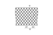
- the expansion portion 32 includes a first reinforcing body 321 made of wires W braided so as to intersect, a first resin layer 322 provided so as to cover the first reinforcing body 321 and the like. Has.
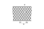
- the shaft portion 33 includes a second reinforcing body 331 made of wires W braided so as to intersect, a second resin layer 332 provided so as to cover the second reinforcing body 331, and the like. Has.
- the first reinforcing body 321 is configured by braiding the wire W so that the knitting angle is ⁇ 1.
- the second reinforcing body 331 is configured by braiding the wire W so as to have a knitting angle ⁇ 2.
- the knitting angles ⁇ 1 and ⁇ 2 are defined as the internal angles in the axial direction among the angles formed by the intersecting wires W, as shown in FIGS. 5 and 6.
- the knitting angle ⁇ 1 of the first reinforcing body 321 is smaller than the knitting angle ⁇ 2 of the second reinforcing body 331. Therefore, the inclination angle of the wire W constituting the first reinforcing body 321 with respect to the axial direction is smaller than that in the case where the knitting angle of the first reinforcing body 321 is larger than the knitting angle of the second reinforcing body 331.
- the knitting angle ⁇ 1 of the first reinforcing body 321 may be larger than the knitting angle ⁇ 2 of the second reinforcing body 331.
- the expansion portion 32 extends in the axial direction, the wire W constituting the first reinforcing body 321 of the expansion portion 32 is deformed so that the inclination angle with respect to the axial direction gradually decreases. Then, when the inclination angle of the wire W constituting the first reinforcing body 321 of the expansion portion 32 with respect to the axial direction becomes approximately zero, the extension of the expansion portion 32 in the axial direction is restricted.
- the knitting angle ⁇ 1 of the first reinforcing body 321 is made smaller than the knitting angle ⁇ 2 of the second reinforcing body 331, the knitting angle of the first reinforcing body 321 is larger than the knitting angle of the second reinforcing body 331.
- the extension distance along the axial direction of the dilation portion 32 accompanying the insertion of the stylet 50 into the catheter 30 becomes shorter.
- the knitting angle ⁇ 1 of the first reinforcing body 321 is not particularly limited, but is 100 degrees to 120 degrees.
- the knitting angle ⁇ 2 of the second reinforcing body 331 is not particularly limited, but is 130 degrees to 150 degrees.
- the first reinforcing body 321 of the expansion portion 32 is braided so as to be sparser than the second reinforcing body 331 of the shaft portion 33. According to this configuration, the expansion portion 32 can be made softer and the elasticity can be increased as compared with the shaft portion 33.
- the wire W is composed of a known shape memory metal or shape memory resin shape memory material.
- a shape memory metal for example, a titanium-based alloy (Ni—Ti, Ti—Pd, Ti—Nb—Sn, etc.) or a copper-based alloy can be used.
- the shape memory resin for example, an acrylic resin, a transisoprene polymer, polynorbornene, a styrene-butadiene copolymer, or polyurethane can be used.
- the contraction distance along the axial direction of the expansion portion 32 accompanying the removal of the stylet 50 from the catheter 30 is the expansion portion accompanying the insertion of the stylet 50 into the catheter 30. It becomes the same as the extension distance along the axial direction of 32.
- the wire diameter of the wire W is preferably 0.1 mm to 0.2 mm.
- the function as a reinforcing body for improving the strength can be suitably exhibited.
- the inner diameter of the wire W can be increased while reducing the outer diameter of the expansion portion 32, so that the burden on the patient's body when the catheter 30 is inserted can be suppressed and the pressure can be suppressed. It is possible to reduce the loss at the same time.
- the cross section of the wire W is circular, but the cross section is not limited to this, and may be a rectangle, a square, an ellipse, or the like.
- the first resin layer 322 of the expansion portion 32 is made of a soft material having a hardness lower than that of the second resin layer 332 of the shaft portion 33. According to this configuration, the expansion portion 32 can be made softer and the elasticity can be increased as compared with the shaft portion 33.
- the first and second resin layers 322 and 332 can be formed by using vinyl chloride, silicon, polyethylene, nylon, urethane, polyurethane, fluororesin, thermoplastic elastomer resin or the like, or by using a composite material thereof.
- Silicone material has high biocompatibility and the material itself is soft, so it has the advantage of not easily damaging blood vessels.
- the polyethylene material is soft and has a hardness that can withstand pressure. Moreover, the polyethylene material has biocompatibility comparable to that of the silicon material.
- the polyethylene material is harder than silicon and has the advantage of being easy to insert into small blood vessels.
- the polyurethane material has the characteristic of becoming soft after insertion. As the materials of the first and second resin layers 322 and 332, applicable materials can be used by taking advantage of the features of these materials.
- the polyurethane material may be coated with a hydrophilic coating.
- the surface of the tube is smooth, the blood vessel can be easily inserted, and the blood vessel wall is not easily damaged. It is difficult for blood and proteins to adhere, and it can be expected to prevent the formation of thrombi.
- the method of forming the expansion portion 32 and the shaft portion 33 is not particularly limited, but can be formed by, for example, dip coating (immersion method) or insert molding.
- the outer surfaces of the reinforcing bodies 321 and 331 may be at least covered with the resin layers 322 and 332.
- the expansion portion 32 has a second side hole 46.
- a plurality of second side holes 46 are provided along the axial direction (four in FIG. 2). It is preferable that a plurality of second side holes 46 are also provided in the circumferential direction.
- the second side hole 46 functions as a blood removal hole.
- the shaft portion 33 has a first side hole 63.
- the first side hole 63 functions as a blood removal hole. It is preferable to have a plurality of first side holes 63 in the circumferential direction.
- the shaft portion 33 is provided with four first side holes 63 in the circumferential direction.
- the tip tip 41 is arranged at the tip of the expansion portion 32 as shown in FIGS. 2 to 4.
- the tip tip 41 has a shape with a tapered tip that is gradually reduced in diameter toward the tip side.
- a flat receiving surface 48 that comes into contact with the flat surface 51D of the stylet 50 used prior to insertion of the catheter 30 into the living body is formed.
- the tip tip 41 is configured to accommodate the tip of the wire W.
- the tip tip 41 has a through hole 47.
- the through hole 47 functions as a hole for blood removal.
- the through hole 47 of the tip tip 41 forms part of the lumen 30A of the catheter 30.
- the tip tip 41 can be formed of, for example, urethane.
- the clamp tube 34 is provided on the base end side of the shaft portion 33. Inside the clamp tube 34, a lumen through which the stylet 50 can be inserted is provided.
- the clamp tube 34 can be formed using the same material as the catheter tube 31.
- the catheter connector 35 connects the shaft portion 33 and the clamp tube 34 as shown in FIGS. 2 and 4. Inside the catheter connector 35, a lumen through which the stylet 50 can be inserted is provided.
- the lock connector 36 is connected to the base end side of the clamp tube 34. Inside the lock connector 36, a lumen through which the stylet 50 can be inserted is provided. A male threaded portion 36A provided with a thread is provided on the outer surface of the lock connector 36 on the base end side.
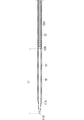
- 7 and 8 are diagrams for explaining the configuration of the stylet 50 according to the present embodiment.
- FIG. 9 is a diagram corresponding to FIG. 8 when the outer layer tube is not provided with a recess.
- FIG. 10 is a diagram corresponding to FIG. 8 in the case where the reduced diameter portion and the concave portion of the outer layer tube are not provided.
- the stylet 50 has an outer layer tube 51 extending in the axial direction and an inner layer tube 52 arranged on the inner circumference of the outer layer tube 51.
- the outer diameter of the outer layer tube 51 is configured to be the same as the inner diameter of the shaft portion 33. It should be noted that the same as the inner diameter of the shaft portion 33 is not only completely the same, but also includes some errors.
- the outer layer tube 51 has a lumen 55 in which the inner layer tube 52 is arranged.
- the tip portion 51A of the outer layer tube 51 is tapered so as to gradually become smaller toward the tip. According to this configuration, since the outer circumference of the tip portion 51A of the outer layer tube 51 has a gentle taper shape, the catheter 30 is integrated with the catheter 30 by inserting the stylet 50 into the catheter 30. It follows the shape and becomes a tapered shape. Therefore, the insertability of the catheter 30 into the living body is improved.
- a recess 51B recessed outward in the radial direction is formed on the inner peripheral surface of the outer layer tube 51.
- the inner diameter of the recess 51B of the outer layer tube 51 is configured to be slightly larger than the outer diameter of the inner layer tube 52.
- the inner layer tube 52 is fixed to the outer layer tube 51 in a state where the tip portion 52C of the reduced diameter portion 52B of the inner layer tube 52 abuts on the tip portion 51C of the recess 51B of the outer layer tube 51.
- the tip of the outer layer tube 51 includes a flat surface 51D with which the receiving surface 48 of the tip tip 41 abuts.
- the total length of the outer layer tube 51 along the axial direction is longer than the total length of the catheter 30 along the axial direction before the expansion portion 32 extends. Further, the total length of the outer layer tube 51 along the axial direction is configured to be the same as the total length of the catheter 30 along the axial direction after the expansion portion 32 is extended.
- the outer diameter of the outer layer tube 51 is not particularly limited, but is 4.0 to 9.0 mm.
- the inner diameter of the outer layer tube 51 is not particularly limited, but is 1.2 to 7.0 mm.
- the recess amount C1 of the recess 51B formed on the inner peripheral surface of the outer layer tube 51 is not particularly limited, but is 0.9 to 3.4 mm.
- the length L1 (see FIG. 7) from the tip portion 51C of the recess 51B of the outer layer tube 51 to the flat surface 51D of the outer layer tube 51 is not particularly limited, but is 50 to 150 mm.
- the outer layer tube 51 is a long body having relatively high rigidity.
- the material constituting the outer layer tube 51 is not particularly limited, but the same materials as those described above for the first and second resin layers 322 and 332 can be used.
- the inner layer tube 52 is provided on the inner circumference of the outer layer tube 51.
- the inner layer tube 52 includes a lumen 52A through which the guide wire GW can be inserted.
- the outer layer tube 51 and the inner layer tube 52 are guided by the guide wire GW and inserted into the living body together with the catheter 30.
- the inner layer tube 52 is configured to have a uniform outer diameter along the axial direction.
- the inner layer tube 52 has a reduced diameter portion 52B whose diameter is reduced toward the proximal end side on the inner peripheral surface of the tip portion 52C.
- the reduced diameter portion 52B has a linear shape as shown in FIG.
- the taper angle ⁇ of the reduced diameter portion 52B is not particularly limited, but is preferably 80 degrees or less. By setting the taper angle to 80 degrees or less in this way, when the catheter assembly 7 is inserted into the living body along the guide wire GW, the guide wire GW is along the diameter-reduced portion 52B and the lumen of the inner layer tube 52. Guided within 52A, it can pass through the lumen 52A of the inner layer tube 52.
- the tip portion 52C of the reduced diameter portion 52B has a predetermined wall thickness D1.
- the wall thickness D1 is preferably substantially the same as the recess amount C1 of the recess 51B formed on the inner peripheral surface of the outer layer tube 51. According to this configuration, no step is generated at the tip end portion 52C of the inner layer tube 52, so that when the catheter assembly 7 is inserted into the living body along the guide wire GW, the guide wire GW is along the reduced diameter portion 52B. , Can pass through the lumen 52A of the inner layer tube 52. Even if the dent amount C1 is larger than the wall thickness D1, the above effect is obtained.
- the catheter assembly 7 when the recess 51B is not provided in the outer layer tube 151, a step is formed only by the wall thickness D1 of the tip portion 52C of the reduced diameter portion 52B. Therefore, when the catheter assembly 7 is inserted into the living body along the guide wire GW, the guide wire GW may come into contact with the tip portion 52C of the reduced diameter portion 52B, and the catheter assembly may not be suitably inserted. ..
- the catheter assembly 7 since the recess 51B is formed in the outer layer tube 51, the catheter assembly 7 can be suitably inserted.
- the configuration in which the outer layer tube 151 is not provided with the recess 51B can suppress the collision of the guide wire GW with the inner layer tube 52 as compared with the configuration in which the reduced diameter portion 52B described below does not exist. It shall be included in.
- FIG. 10 as a comparative example, a catheter assembly 90 of an inner layer tube 952 in which the reduced diameter portion 52B is not provided and an outer layer tube 151 in which the recess 51B is not provided is disclosed.
- a step is formed by the thickness of the inner layer tube 952. Therefore, when the catheter assembly 90 is inserted into the living body along the guide wire GW, it is difficult for the guide wire GW to come into contact with the inner layer tube 952 to insert the catheter assembly 90.
- the outer diameter of the inner layer tube 52 is not particularly limited, but is 1.3 to 7.0 mm.
- the inner diameter of the inner layer tube 52 is not particularly limited, but is 1.1 to 5.0 mm.
- the inner layer tube 52 is a long body having relatively high rigidity.
- the inner layer tube 52 is made of a material harder than the outer layer tube 51.
- the material constituting the inner layer tube 52 is not particularly limited, but the same materials as those described above for the first and second resin layers 322 and 332 can be used. According to this configuration, it is possible to increase the rigidity of the base end of the stylet 50 while softening the tip of the stylet 50. Therefore, when the catheter assembly 7 is inserted into the living body, it is possible to prevent damage to the living tissue and to transmit the pushing force toward the tip side by the operation at hand to the tip tip 41. ..
- the stylet 50 further includes a stylet hub 53 to which the base ends of the outer layer tube 51 and the inner layer tube 52 are fixed, and a screw ring 54 provided at the tip of the stylet hub 53.
- the stylet hub 53 is provided at the base ends of the outer layer tube 51 and the inner layer tube 52, and is configured to be grippable.
- the stylet 50 is removed from the catheter 30 by indwelling the catheter 30 in the living body and then pulling out the stylet hub 53 toward the proximal end side.
- the screw ring 54 has a female screw portion (not shown) having a screw groove on the inner surface of the lumen.
- the stylet 50 can be attached to the catheter 30 by screwing the female threaded portion of the screw ring 54 into the male threaded portion 36A of the lock connector 36.
- the inner layer tube 52 is fixed to the outer layer tube 51 to manufacture the stylet 50.
- the stylet 50 is inserted through the lumen 30A of the catheter 30.
- the stylet 50 passes through the inside of the shaft portion 33 and the expansion portion 32 in order, and the flat surface 51D of the outer layer tube 51 of the stylet 50 comes into contact with the receiving surface 48 of the tip tip 41.
- the axial total length of the outer layer tube 51 is longer than the axial total length of the catheter 30 before the expansion portion 32 is extended. Therefore, the expansion portion 32 is pressed toward the tip end side in a state where the flat surface 51D of the outer layer tube 51 of the stylet 50 is in contact with the receiving surface 48 of the tip tip 41.
- the catheter 30 receives a force to extend in the axial direction, and the expansion portion 32 of the catheter 30, which has relatively high elasticity, extends in the axial direction.
- the stylet 50 is attached to the catheter 30 by screwing the female screw portion of the screw ring 54 into the male screw portion 36A provided on the lock connector 36 of the catheter.
- the catheter 30 through which the stylet 50 is inserted is inserted along the guide wire GW that has been previously inserted into the target site in the living body.
- the catheter assembly 7 is provided along the guide wire GW. Can be suitably inserted.
- the outer diameter of the expansion portion 32 is substantially the same as the outer diameter of the shaft portion 33, and the catheter 30 can be inserted into the living body with minimal invasiveness. It is possible to reduce the burden on the patient's body.
- the catheter 30 is inserted into the living body until the through hole 47 of the tip tip 41 and the second side hole 46 of the catheter tube 31 are arranged in the right atrium and the first side hole 63 of the catheter tube 31 is arranged in the inferior vena cava. And detain. With the through hole 47, the first side hole 63, and the second side hole 46 arranged for the blood removal target, the dilation portion 32 is arranged in the inferior vena cava, which is a relatively large blood vessel, and the shaft portion 33 is relatively. It is placed in the femoral vein, which is a small blood vessel.
- the stylet 50 and the guide wire are removed from the catheter 30.
- the stylet 50 and the guide wire are once pulled out to the location of the clamping tube 34 of the catheter 30, clamped with forceps (not shown), and then completely removed from the catheter 30.
- the catheter 30 is released from the axially extending force that the catheter 30 received from the stylet 50. Therefore, the expansion portion 32 contracts in the axial direction, and the inner diameter of the expansion portion 32 becomes large. As a result, the pressure loss in the expansion portion 32 can be reduced and the required flow rate of the liquid can be secured.
- the lock connector 36 of the catheter 30 is connected to the blood removal tube 11 of the extracorporeal circulatory device of FIG. After confirming that the connection of the catheter on the blood feeding side is completed, the forceps of the clamp tube 34 are released to start extracorporeal circulation.
- the catheter 30 is removed from the blood vessel, and hemostasis is repaired by a surgical procedure if necessary at the insertion site.
- the stylet 50 is a stylet 50 configured to be insertable into a catheter 30 provided with a lumen 30A capable of circulating blood.
- the stylet 50 has an outer layer tube 51 extending in the axial direction, and an inner layer tube 52 that is arranged on the inner circumference of the outer layer tube 51 and has a hollow shape and is harder than the outer layer tube 51.
- the inner layer tube 52 has a reduced diameter portion 52B on the inner peripheral surface of the tip end portion of the inner layer tube 52, whose diameter is reduced toward the proximal end side in the axial direction.
- the outer layer tube 51 extending in the axial direction and the inner layer tube 52 arranged on the inner circumference of the outer layer tube 51 and harder than the outer layer tube 51 are provided. While preventing the occurrence of kink and breakage, the tip side can be made flexible and the hardness on the base end side can be maintained at a desired hardness. Further, since the inner layer tube 52 has the reduced diameter portion 52B, when the catheter assembly 7 is inserted into the living body along the reduced diameter portion 52B, the guide wire GW has the lumen 52A of the inner layer tube 52 along the reduced diameter portion 52B. Can pass through. From the above, while preventing the occurrence of kink and breakage, the tip side is made flexible to maintain the hardness of the base end side, and the catheter assembly 7 can be suitably inserted along the guide wire GW. Let 50 can be provided.
- the range of the tip of the stylet 50 having flexibility is appropriately controlled by appropriately changing the position of the tip of the inner layer tube 52 in the axial direction with respect to the outer layer tube 51. can do.
- the outer layer tube 51 has a recess 51B recessed outward in the radial direction on the inner peripheral surface of the outer layer tube 51, and the tip portion 52C of the inner layer tube 52 abuts on the tip portion 51C of the recess 51B of the outer layer tube 51.
- the inner layer tube 52 is fixed to the outer layer tube 51.
- the catheter assembly 7 can be more preferably inserted along the guide wire GW.
- the reduced diameter portion 52B has a linear shape. According to the stylet 50 configured in this way, the reduced diameter portion 52B can be easily formed.
- the stylet 50 has been applied to the catheter 30 with one lumen 30A.
- it can also be used for catheters 60 with double lumens, as shown in FIGS. 11-13.
- the configuration of the catheter 60 having a double lumen will be described with reference to FIGS. 11 to 13.
- the catheter 60 is a so-called double lumen catheter that can simultaneously send and remove blood. Therefore, in the present embodiment, in the extracorporeal circulation device of FIG. 1, two catheters, the venous side catheter (blood removal catheter) 5 and the arterial side catheter (blood feeding catheter) 6, are not used, but one. The procedure is performed using only the catheter 60.
- a third tube 161 having a first lumen 61 communicating with the blood feeding side hole 163 has a double tube structure arranged in the lumen of the shaft portion 133. Have.
- the pump of the extracorporeal circulation device is operated to remove blood from the patient's vein (large vein), gas is exchanged in the blood by an artificial lung to oxygenate the blood, and then the blood is oxygenated.
- a venous-venous (Veno-Venous, VV) artificial lung extracorporeal blood circulation can be performed.
- the catheter 60 includes an expansion portion 32, a shaft portion 133, a tip tip 41 arranged at the tip of the expansion portion 32, and a third catheter 60 arranged in the lumen of the shaft portion 133. It has a tube 161 and. Since the configuration of the expansion portion 32 and the tip tip 41 is the same as that of the catheter 30 of the first embodiment, the description thereof will be omitted.
- the catheter 60 has a first lumen 61 that functions as a blood supply channel and a second lumen 62 that functions as a blood removal channel.
- the first lumen 61 is formed in the lumen of the third tube 161.
- the second lumen 62 is formed in the lumen of the expansion portion 32 and the shaft portion 133, and penetrates from the tip end to the base end.
- the shaft portion 133 is provided with a blood feeding side hole 163 that communicates with the first lumen 61, which is a blood feeding channel.
- the shaft portion 133 is provided with a blood removal side hole 164 communicating with the second lumen 62, which is a blood removal path.
- the blood feeding side hole 163 and the blood removal side hole 164 are formed in an elliptical shape.
- the third tube 161 is inserted into the second lumen 62 from the base end side of the shaft portion 133 and is connected to the blood feeding side hole 163.
- the blood feeding side hole 163 is arranged in the blood feeding target in the living body, and the blood oxygenated by the artificial lung is sent out into the living body through the blood feeding side hole 163.
- the through hole 47 included in the tip tip 41, the second side hole 46 included in the expansion portion 32, and the blood removal side hole 164 provided in the shaft portion 133 are arranged in different blood removal targets in the living body to efficiently remove blood. It is configured to be able to do. Further, even if the through hole 47, the second side hole 46, or the blood removal side hole 164 is adsorbed to the blood vessel wall and blocked, blood can be removed from the unclosed hole. Extracorporeal circulation can be performed stably.
- the catheter 60 is inserted from the internal jugular vein of the neck, and the tip is placed in the inferior vena cava via the superior vena cava and the right atrium.
- the blood supply target is the right atrium
- the blood removal target is the superior vena cava and the inferior vena cava.
- the through hole 47 of the tip tip 41, the second side hole 46 of the expansion portion 32 are in the inferior vena cava, and the blood of the shaft portion 133 is removed. It is inserted and placed in the living body so that the side hole 164 is arranged in the internal jugular vein.
- the expansion portion 32 is configured to have an inner diameter larger than that of the shaft portion 133.
- the dilation portion 32 With the through hole 47, the second side hole 46, and the blood removal side hole 164 arranged for the blood removal target, the dilation portion 32 is arranged in the inferior vena cava, which is a relatively large blood vessel, and the shaft portion 133 is compared. It is placed in the femoral vein, which is a small blood vessel.
- the lock connector 136 is provided in parallel with the first lock connector 137 communicating with the first lumen 61 and the first lock connector 137, and is a second lock connector communicating with the second lumen 62. It has 138 and.
- the lock connector 136 is a Y-shaped Y connector formed by branching the first lock connector 137 from the second lock connector 138.
- the first lock connector 137 is connected to the base end portion of the third tube 161.
- the second lock connector 138 is coaxially connected to the base end portion of the shaft portion 133.
- a blood feeding tube (blood feeding line) is connected to the first lock connector 137, and a blood removal tube (blood removing line) is connected to the second lock connector 138.
- one catheter can perform both blood removal and blood transfer functions.
- the catheter assembly 8 has a configuration in which the stylet 250 as shown in FIG. 14 projects from the tip of the catheter 30.
- the tip of the outer layer tube 51 may not have a flat surface 51D and may have an edgeless shape.
- the stylet 81 when the stylet 81 is uniformly and relatively hard in the axial direction, as shown in FIG. 15, when the catheter assembly 80 is inserted along the guide wire GW, the stylet 81 is inserted. It is difficult to bend, has poor followability to the guide wire GW, and may unintentionally come into contact with blood vessels.
- the catheter assembly 8 according to the modified example the stylet 250 having flexibility on the distal end side and desired hardness on the proximal end side is used. Therefore, as shown in FIG. 14, the stylet 250 is used. The let 250 is easy to bend, has good followability to the guide wire GW, and reduces the risk of damaging blood vessels.
- the tip of the inner layer tube 52 is arranged closer to the proximal end side than the distal end of the catheter 30 with the stylet 250 inserted into the catheter 30. According to this configuration, the operator can grasp the base end side having a high hardness in which the inner layer tube 52 is arranged, so that the operation becomes easy.
- the catheter according to the present invention has been described above through the embodiments, the present invention is not limited to the configurations described in the embodiments and modifications, and may be appropriately modified based on the description of the claims. It is possible.
- the reduced diameter portion 52B has a linear shape.
- the diameter-reduced portion 152B may have a curved shape so as to be convex toward the proximal end side.
- the guide wire GW is suitable for the lumen 52A of the inner layer tube 152 along the reduced diameter portion 152B. Will be guided to.
- the material constituting the wire W is not limited to a shape memory material as long as it has a restoring force to deform and return to the original shape and has a function of reinforcing the resin layer, for example. It can be made of a known elastic material.
- catheter assembly 30, 60, 230 catheters (percutaneous catheters), 30A catheter lumen, 50, 150, 250 stylet, 51, 151 outer layer tube, 51B recess, 51C recessed tip, 52, 152 inner layer tube, 52B, 152B reduced diameter part, 52C The tip of the inner layer tube.
Landscapes
- Health & Medical Sciences (AREA)
- Life Sciences & Earth Sciences (AREA)
- Heart & Thoracic Surgery (AREA)
- Hematology (AREA)
- Engineering & Computer Science (AREA)
- Anesthesiology (AREA)
- Biomedical Technology (AREA)
- Animal Behavior & Ethology (AREA)
- General Health & Medical Sciences (AREA)
- Public Health (AREA)
- Veterinary Medicine (AREA)
- Pulmonology (AREA)
- Biophysics (AREA)
- Vascular Medicine (AREA)
- Cardiology (AREA)
- Media Introduction/Drainage Providing Device (AREA)
Priority Applications (4)
| Application Number | Priority Date | Filing Date | Title |
|---|---|---|---|
| EP22739321.2A EP4272796A4 (en) | 2021-01-13 | 2022-01-06 | STYLET AND CATHETER ARRANGEMENT |
| JP2022543110A JP7157283B1 (ja) | 2021-01-13 | 2022-01-06 | スタイレットおよびカテーテル組立体 |
| JP2022161348A JP7732960B2 (ja) | 2021-01-13 | 2022-10-06 | スタイレットおよびカテーテル組立体 |
| US18/214,005 US20230347108A1 (en) | 2021-01-13 | 2023-06-26 | Stylet and catheter assembly |
Applications Claiming Priority (2)
| Application Number | Priority Date | Filing Date | Title |
|---|---|---|---|
| JP2021-003399 | 2021-01-13 | ||
| JP2021003399 | 2021-01-13 |
Related Child Applications (1)
| Application Number | Title | Priority Date | Filing Date |
|---|---|---|---|
| US18/214,005 Continuation US20230347108A1 (en) | 2021-01-13 | 2023-06-26 | Stylet and catheter assembly |
Publications (1)
| Publication Number | Publication Date |
|---|---|
| WO2022153912A1 true WO2022153912A1 (ja) | 2022-07-21 |
Family
ID=82447309
Family Applications (1)
| Application Number | Title | Priority Date | Filing Date |
|---|---|---|---|
| PCT/JP2022/000180 Ceased WO2022153912A1 (ja) | 2021-01-13 | 2022-01-06 | スタイレットおよびカテーテル組立体 |
Country Status (4)
| Country | Link |
|---|---|
| US (1) | US20230347108A1 (https=) |
| EP (1) | EP4272796A4 (https=) |
| JP (2) | JP7157283B1 (https=) |
| WO (1) | WO2022153912A1 (https=) |
Families Citing this family (1)
| Publication number | Priority date | Publication date | Assignee | Title |
|---|---|---|---|---|
| JP7854564B1 (ja) | 2025-12-26 | 2026-05-01 | 平河ヒューテック株式会社 | カテーテル用チューブ、カテーテル用チューブの連続体及びカテーテル用チューブの製造方法 |
Citations (7)
| Publication number | Priority date | Publication date | Assignee | Title |
|---|---|---|---|---|
| JPH01310666A (ja) | 1988-03-25 | 1989-12-14 | Baxter Internatl Inc | 軟先端カテーテル |
| JPH05253304A (ja) * | 1992-03-13 | 1993-10-05 | Terumo Corp | 血管カテーテル |
| US20100063480A1 (en) * | 2008-09-10 | 2010-03-11 | Boston Scientific Scimed, Inc. | Medical devices and tapered tubular members for use in medical devices |
| JP5059305B2 (ja) | 2000-01-18 | 2012-10-24 | コラフロ リミテッド ライアビリティ カンパニー | 高性能カニューレ |
| JP2015019851A (ja) * | 2013-07-19 | 2015-02-02 | 朝日インテック株式会社 | カテーテル |
| JP2018050722A (ja) * | 2016-09-27 | 2018-04-05 | テルモ株式会社 | カテーテルおよびその使用方法 |
| JP2021003399A (ja) | 2019-06-27 | 2021-01-14 | 大和化学工業株式会社 | おしぼり又はウェットティシューの保存剤 |
Family Cites Families (4)
| Publication number | Priority date | Publication date | Assignee | Title |
|---|---|---|---|---|
| JPH08182765A (ja) * | 1994-12-28 | 1996-07-16 | Nippon Zeon Co Ltd | イントロデューサー |
| JP3409270B2 (ja) * | 1996-03-26 | 2003-05-26 | 日本シャーウッド株式会社 | ダブルルーメンカテーテル |
| US9393382B2 (en) * | 2009-05-05 | 2016-07-19 | Robert W. Heck | High-flow tapered peripheral IV catheter with side outlets |
| US9827122B2 (en) | 2015-05-04 | 2017-11-28 | Abbott Cardiovascular Systems Inc. | System for a catheter |
-
2022
- 2022-01-06 EP EP22739321.2A patent/EP4272796A4/en active Pending
- 2022-01-06 WO PCT/JP2022/000180 patent/WO2022153912A1/ja not_active Ceased
- 2022-01-06 JP JP2022543110A patent/JP7157283B1/ja active Active
- 2022-10-06 JP JP2022161348A patent/JP7732960B2/ja active Active
-
2023
- 2023-06-26 US US18/214,005 patent/US20230347108A1/en active Pending
Patent Citations (7)
| Publication number | Priority date | Publication date | Assignee | Title |
|---|---|---|---|---|
| JPH01310666A (ja) | 1988-03-25 | 1989-12-14 | Baxter Internatl Inc | 軟先端カテーテル |
| JPH05253304A (ja) * | 1992-03-13 | 1993-10-05 | Terumo Corp | 血管カテーテル |
| JP5059305B2 (ja) | 2000-01-18 | 2012-10-24 | コラフロ リミテッド ライアビリティ カンパニー | 高性能カニューレ |
| US20100063480A1 (en) * | 2008-09-10 | 2010-03-11 | Boston Scientific Scimed, Inc. | Medical devices and tapered tubular members for use in medical devices |
| JP2015019851A (ja) * | 2013-07-19 | 2015-02-02 | 朝日インテック株式会社 | カテーテル |
| JP2018050722A (ja) * | 2016-09-27 | 2018-04-05 | テルモ株式会社 | カテーテルおよびその使用方法 |
| JP2021003399A (ja) | 2019-06-27 | 2021-01-14 | 大和化学工業株式会社 | おしぼり又はウェットティシューの保存剤 |
Non-Patent Citations (1)
| Title |
|---|
| See also references of EP4272796A4 |
Also Published As
| Publication number | Publication date |
|---|---|
| US20230347108A1 (en) | 2023-11-02 |
| JP7157283B1 (ja) | 2022-10-19 |
| EP4272796A1 (en) | 2023-11-08 |
| JP7732960B2 (ja) | 2025-09-02 |
| EP4272796A4 (en) | 2024-07-24 |
| JP2022180644A (ja) | 2022-12-06 |
| JPWO2022153912A1 (https=) | 2022-07-21 |
Similar Documents
| Publication | Publication Date | Title |
|---|---|---|
| JP6813571B2 (ja) | 経皮カテーテルおよび経皮カテーテル用チューブの製造方法 | |
| JP6876710B2 (ja) | カテーテル | |
| US11260159B2 (en) | Percutaneous catheter and percutaneous catheter assembly | |
| US20220401638A1 (en) | Percutaneous catheter | |
| JP7732960B2 (ja) | スタイレットおよびカテーテル組立体 | |
| JP6813570B2 (ja) | 経皮カテーテル | |
| US20220401696A1 (en) | Stylet for a percutaneous catheter | |
| WO2018225331A1 (ja) | カテーテル | |
| JP6730430B2 (ja) | 経皮カテーテル組立体、経皮カテーテル、およびダイレーター | |
| JP7684489B2 (ja) | 経皮カテーテル | |
| US20210290904A1 (en) | Catheter assembly | |
| JP7723536B2 (ja) | シースおよび医療用組立体 | |
| WO2022168720A1 (ja) | 経皮カテーテル | |
| WO2022168719A1 (ja) | 経皮カテーテル | |
| JP7710903B2 (ja) | 経皮カテーテル | |
| WO2021177165A1 (ja) | 経皮カテーテルおよび経皮カテーテルの使用方法 | |
| US20190321539A1 (en) | Catheter for feeding blood to a vessel |
Legal Events
| Date | Code | Title | Description |
|---|---|---|---|
| ENP | Entry into the national phase |
Ref document number: 2022543110 Country of ref document: JP Kind code of ref document: A |
|
| 121 | Ep: the epo has been informed by wipo that ep was designated in this application |
Ref document number: 22739321 Country of ref document: EP Kind code of ref document: A1 |
|
| ENP | Entry into the national phase |
Ref document number: 2022739321 Country of ref document: EP Effective date: 20230731 |
|
| NENP | Non-entry into the national phase |
Ref country code: DE |