WO2022153803A1 - 需要調整制御システム、需要調整制御方法、及びプログラム - Google Patents
需要調整制御システム、需要調整制御方法、及びプログラム Download PDFInfo
- Publication number
- WO2022153803A1 WO2022153803A1 PCT/JP2021/047444 JP2021047444W WO2022153803A1 WO 2022153803 A1 WO2022153803 A1 WO 2022153803A1 JP 2021047444 W JP2021047444 W JP 2021047444W WO 2022153803 A1 WO2022153803 A1 WO 2022153803A1
- Authority
- WO
- WIPO (PCT)
- Prior art keywords
- demand adjustment
- adjustment control
- target
- demand
- control
- Prior art date
Links
- 238000000034 method Methods 0.000 title claims description 24
- 230000004044 response Effects 0.000 claims description 15
- 230000008859 change Effects 0.000 abstract description 10
- 230000008901 benefit Effects 0.000 description 18
- 230000000052 comparative effect Effects 0.000 description 10
- 238000010586 diagram Methods 0.000 description 10
- 238000003860 storage Methods 0.000 description 8
- 230000003247 decreasing effect Effects 0.000 description 7
- 230000004913 activation Effects 0.000 description 6
- 238000004891 communication Methods 0.000 description 6
- 230000008569 process Effects 0.000 description 6
- 230000007423 decrease Effects 0.000 description 5
- 238000004378 air conditioning Methods 0.000 description 4
- 238000004590 computer program Methods 0.000 description 4
- 238000001816 cooling Methods 0.000 description 4
- 230000010354 integration Effects 0.000 description 4
- 239000004065 semiconductor Substances 0.000 description 4
- 238000007792 addition Methods 0.000 description 2
- 238000007405 data analysis Methods 0.000 description 2
- 238000007710 freezing Methods 0.000 description 2
- 230000008014 freezing Effects 0.000 description 2
- 238000010438 heat treatment Methods 0.000 description 2
- 238000009423 ventilation Methods 0.000 description 2
- 238000004458 analytical method Methods 0.000 description 1
- 238000013459 approach Methods 0.000 description 1
- 230000000694 effects Effects 0.000 description 1
- 230000006870 function Effects 0.000 description 1
- 238000004519 manufacturing process Methods 0.000 description 1
- 230000004048 modification Effects 0.000 description 1
- 238000012986 modification Methods 0.000 description 1
- 230000003287 optical effect Effects 0.000 description 1
- 238000002360 preparation method Methods 0.000 description 1
- 238000012545 processing Methods 0.000 description 1
- 238000010257 thawing Methods 0.000 description 1
- 230000000007 visual effect Effects 0.000 description 1
- 230000003313 weakening effect Effects 0.000 description 1
Images


Classifications
-
- H—ELECTRICITY
- H02—GENERATION; CONVERSION OR DISTRIBUTION OF ELECTRIC POWER
- H02J—CIRCUIT ARRANGEMENTS OR SYSTEMS FOR SUPPLYING OR DISTRIBUTING ELECTRIC POWER; SYSTEMS FOR STORING ELECTRIC ENERGY
- H02J3/00—Circuit arrangements for ac mains or ac distribution networks
- H02J3/12—Circuit arrangements for ac mains or ac distribution networks for adjusting voltage in ac networks by changing a characteristic of the network load
- H02J3/14—Circuit arrangements for ac mains or ac distribution networks for adjusting voltage in ac networks by changing a characteristic of the network load by switching loads on to, or off from, network, e.g. progressively balanced loading
-
- G—PHYSICS
- G05—CONTROLLING; REGULATING
- G05B—CONTROL OR REGULATING SYSTEMS IN GENERAL; FUNCTIONAL ELEMENTS OF SUCH SYSTEMS; MONITORING OR TESTING ARRANGEMENTS FOR SUCH SYSTEMS OR ELEMENTS
- G05B19/00—Programme-control systems
- G05B19/02—Programme-control systems electric
- G05B19/04—Programme control other than numerical control, i.e. in sequence controllers or logic controllers
- G05B19/042—Programme control other than numerical control, i.e. in sequence controllers or logic controllers using digital processors
-
- G—PHYSICS
- G06—COMPUTING; CALCULATING OR COUNTING
- G06Q—INFORMATION AND COMMUNICATION TECHNOLOGY [ICT] SPECIALLY ADAPTED FOR ADMINISTRATIVE, COMMERCIAL, FINANCIAL, MANAGERIAL OR SUPERVISORY PURPOSES; SYSTEMS OR METHODS SPECIALLY ADAPTED FOR ADMINISTRATIVE, COMMERCIAL, FINANCIAL, MANAGERIAL OR SUPERVISORY PURPOSES, NOT OTHERWISE PROVIDED FOR
- G06Q50/00—Information and communication technology [ICT] specially adapted for implementation of business processes of specific business sectors, e.g. utilities or tourism
- G06Q50/06—Energy or water supply
-
- H—ELECTRICITY
- H02—GENERATION; CONVERSION OR DISTRIBUTION OF ELECTRIC POWER
- H02J—CIRCUIT ARRANGEMENTS OR SYSTEMS FOR SUPPLYING OR DISTRIBUTING ELECTRIC POWER; SYSTEMS FOR STORING ELECTRIC ENERGY
- H02J13/00—Circuit arrangements for providing remote indication of network conditions, e.g. an instantaneous record of the open or closed condition of each circuitbreaker in the network; Circuit arrangements for providing remote control of switching means in a power distribution network, e.g. switching in and out of current consumers by using a pulse code signal carried by the network
- H02J13/00004—Circuit arrangements for providing remote indication of network conditions, e.g. an instantaneous record of the open or closed condition of each circuitbreaker in the network; Circuit arrangements for providing remote control of switching means in a power distribution network, e.g. switching in and out of current consumers by using a pulse code signal carried by the network characterised by the power network being locally controlled
-
- H—ELECTRICITY
- H02—GENERATION; CONVERSION OR DISTRIBUTION OF ELECTRIC POWER
- H02J—CIRCUIT ARRANGEMENTS OR SYSTEMS FOR SUPPLYING OR DISTRIBUTING ELECTRIC POWER; SYSTEMS FOR STORING ELECTRIC ENERGY
- H02J3/00—Circuit arrangements for ac mains or ac distribution networks
-
- H—ELECTRICITY
- H02—GENERATION; CONVERSION OR DISTRIBUTION OF ELECTRIC POWER
- H02J—CIRCUIT ARRANGEMENTS OR SYSTEMS FOR SUPPLYING OR DISTRIBUTING ELECTRIC POWER; SYSTEMS FOR STORING ELECTRIC ENERGY
- H02J3/00—Circuit arrangements for ac mains or ac distribution networks
- H02J3/003—Load forecast, e.g. methods or systems for forecasting future load demand
-
- H—ELECTRICITY
- H02—GENERATION; CONVERSION OR DISTRIBUTION OF ELECTRIC POWER
- H02J—CIRCUIT ARRANGEMENTS OR SYSTEMS FOR SUPPLYING OR DISTRIBUTING ELECTRIC POWER; SYSTEMS FOR STORING ELECTRIC ENERGY
- H02J3/00—Circuit arrangements for ac mains or ac distribution networks
- H02J3/12—Circuit arrangements for ac mains or ac distribution networks for adjusting voltage in ac networks by changing a characteristic of the network load
- H02J3/14—Circuit arrangements for ac mains or ac distribution networks for adjusting voltage in ac networks by changing a characteristic of the network load by switching loads on to, or off from, network, e.g. progressively balanced loading
- H02J3/144—Demand-response operation of the power transmission or distribution network
-
- G—PHYSICS
- G05—CONTROLLING; REGULATING
- G05B—CONTROL OR REGULATING SYSTEMS IN GENERAL; FUNCTIONAL ELEMENTS OF SUCH SYSTEMS; MONITORING OR TESTING ARRANGEMENTS FOR SUCH SYSTEMS OR ELEMENTS
- G05B2219/00—Program-control systems
- G05B2219/20—Pc systems
- G05B2219/26—Pc applications
- G05B2219/2639—Energy management, use maximum of cheap power, keep peak load low
-
- H—ELECTRICITY
- H02—GENERATION; CONVERSION OR DISTRIBUTION OF ELECTRIC POWER
- H02J—CIRCUIT ARRANGEMENTS OR SYSTEMS FOR SUPPLYING OR DISTRIBUTING ELECTRIC POWER; SYSTEMS FOR STORING ELECTRIC ENERGY
- H02J2310/00—The network for supplying or distributing electric power characterised by its spatial reach or by the load
- H02J2310/10—The network having a local or delimited stationary reach
- H02J2310/12—The local stationary network supplying a household or a building
- H02J2310/14—The load or loads being home appliances
-
- H—ELECTRICITY
- H02—GENERATION; CONVERSION OR DISTRIBUTION OF ELECTRIC POWER
- H02J—CIRCUIT ARRANGEMENTS OR SYSTEMS FOR SUPPLYING OR DISTRIBUTING ELECTRIC POWER; SYSTEMS FOR STORING ELECTRIC ENERGY
- H02J2310/00—The network for supplying or distributing electric power characterised by its spatial reach or by the load
- H02J2310/50—The network for supplying or distributing electric power characterised by its spatial reach or by the load for selectively controlling the operation of the loads
- H02J2310/56—The network for supplying or distributing electric power characterised by its spatial reach or by the load for selectively controlling the operation of the loads characterised by the condition upon which the selective controlling is based
- H02J2310/58—The condition being electrical
- H02J2310/60—Limiting power consumption in the network or in one section of the network, e.g. load shedding or peak shaving
Definitions
- This disclosure relates to a demand adjustment control system, a demand adjustment control method, and a program that control a device so as to adjust the demand when a demand adjustment request is made.
- Patent Document 1 discloses an electronic device for power saving control.
- This electronic device includes a transmitter / receiver, a data analysis block, a display control block, a power saving activation line control block, and a command signal output block.
- the transmitter / receiver acquires the actual power consumption data and the power consumption prediction data for each time zone provided by the power supply management system.
- the data analysis block analyzes changes in the actual power consumption data and the power usage prediction data, and creates graph data that displays the analysis results.
- the display control block displays a graph on the display and also displays a power saving activation setting line on the graph.
- the power saving activation line control block adjusts the power saving activation setting line, determines it at an arbitrary position, and sets the value at the determined position as the power saving activation value. Then, when the value of the power consumption actual data and / or the power consumption prediction data exceeds the power saving activation value, the command signal output block outputs the power saving command signal to the device to be the power saving target.
- This disclosure provides a demand adjustment control system, etc. that can easily reduce the impact on facilities when a demand adjustment request is made.
- the demand adjustment control system includes an acquisition unit, a determination unit, and a control unit.
- the acquisition unit acquires the target adjustment amount based on the temporary demand adjustment request.
- the determination unit determines a target device to be subject to demand adjustment control based on the target adjustment amount acquired by the acquisition unit from a group of devices installed in the facility.
- the control unit executes the demand adjustment control of the target device so that the adjustment amount by the target device falls within the range of the target adjustment amount during the execution period of the demand adjustment request.
- the device group includes a first device whose mode of demand adjustment control is not changed during the implementation period, and a second device whose mode of demand adjustment control can be changed during the implementation period.
- the demand adjustment control method includes an acquisition step, a determination step, and a control step.
- the acquisition step the target adjustment amount based on the temporary demand adjustment request is acquired.
- the determination step the target equipment to be subject to the demand adjustment control is determined from the equipment group installed in the facility based on the target adjustment amount acquired in the acquisition step.
- the control step the demand adjustment control of the target device is executed so that the adjustment amount by the target device falls within the range of the target adjustment amount during the execution period of the demand adjustment request.
- the device group includes a first device whose mode of demand adjustment control is not changed during the implementation period, and a second device whose mode of demand adjustment control can be changed during the implementation period.
- the program according to one aspect of the present disclosure causes the processor to execute the demand adjustment control method.
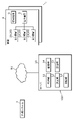
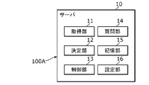
- FIG. 1 is a block diagram showing an overall configuration including a demand adjustment control system according to the first embodiment.
- FIG. 2 is a schematic diagram showing an example of demand adjustment control by the demand adjustment control system according to the first embodiment.
- FIG. 3 is a flowchart showing an operation example of the demand adjustment control system according to the first embodiment.
- FIG. 4 is a graph showing an example of demand adjustment control by the demand adjustment control system according to the first embodiment when the electric power demand is tight.
- FIG. 5 is a graph showing an example of demand adjustment control by the demand adjustment control system according to the first embodiment when the fluctuation of the electric power demand is suppressed.
- FIG. 6 is a graph showing another example of demand adjustment control by the demand adjustment control system according to the first embodiment when the fluctuation of the electric power demand is suppressed.
- FIG. 1 is a block diagram showing an overall configuration including a demand adjustment control system according to the first embodiment.
- FIG. 2 is a schematic diagram showing an example of demand adjustment control by the demand adjustment control system according to the first embodiment.
- FIG. 7 is a graph showing an example of the result of demand adjustment control by the demand adjustment control system of the comparative example.
- FIG. 8 is a graph showing an example of the result of demand adjustment control by the demand adjustment control system according to the first embodiment.
- FIG. 9 is a block diagram showing a configuration of the demand adjustment control system according to the second embodiment.
- FIG. 10A is an explanatory diagram of problems that may occur in the demand adjustment control by the demand adjustment control system according to the first embodiment.
- FIG. 10B is an explanatory diagram of problems that may occur in the demand adjustment control by the demand adjustment control system according to the first embodiment.
- FIG. 11 is a graph showing an example of the result of demand adjustment control by the demand adjustment control system according to the second embodiment.
- FIG. 12 is a block diagram showing a configuration of a demand adjustment control system according to a modified example of the first embodiment.
- the power saving request is made by stopping the operation of the power saving target device or changing the operation mode of the power saving target device.
- the power saving control was performed accordingly.
- VPP Virtual Power Plant
- VPP Virtual Power Plant
- VPP Virtual Power Plant
- in principle in order to keep the magnitude and frequency of the voltage supplied by the electric power company, etc. constant, it is a principle to achieve the same amount at the same time so that the demand and supply and demand of electric power are always matched, and only the power saving request is made. Instead, a power increase request may be made to consume the excess power generated.
- the demand adjustment (power saving) target is obtained by repeatedly changing the operation of the device subject to the demand adjustment (power saving) so as to fall within the adjustment amount (power saving amount) commanded by the demand adjustment request (power saving request). It can affect the facility where the equipment is installed.
- the facility is a store such as a convenience store
- the equipment to be saved power is a lighting fixture installed in the sales floor.
- the dimming rate of the lighting equipment is repeatedly increased or decreased in response to a request for power saving, the customer may feel uncomfortable because the customer visually senses a change in the lighting environment of the store.
- a predetermined numerical value for example, an integrated value of the adjustment amount described later
- a threshold value for example, a target adjustment amount described later
- a threshold value may be included in the other branching condition.
- one of the branching conditions may be "a predetermined numerical value is above (or below) a threshold value" or "a predetermined numerical value is above (or below) the threshold value”.
- FIG. 1 is a block diagram showing an overall configuration including the demand adjustment control system 100 according to the first embodiment.
- the demand adjustment control system 100 determines the target device 3 to be subject to the demand adjustment control from the device group 2 in response to the demand adjustment request from the external system 7 operated by, for example, an electric power company or an aggregator, and determines the target device 3 to be the target device 3 of the target device 3. It is a system for executing demand adjustment control.
- the demand adjustment control of the target device 3 may include not intentionally controlling the target device 3 when, for example, a demand adjustment request is required that the demand adjustment control is unnecessary.
- the number of the target devices 3 that execute the demand adjustment control may be zero, but such a case can also be included in the demand adjustment control of the target device 3.
- the demand adjustment request is not a permanent request, but a temporary request such as the above-mentioned DR.
- the demand adjustment request may include a peak cut for keeping the power consumption low during the time period when the power demand peaks.
- the demand adjustment request may include a request for keeping the power consumption low during the time when the power price is relatively high, based on the power price in the power supply and demand market.
- the device group 2 includes the device 20 installed in the facility 4 that can be subject to demand adjustment control. For example, when there is one facility 4, the device group 2 includes the device 20 installed in the facility 4. Further, for example, when there are a plurality of facilities 4, the device group 2 includes all the devices 20 installed in each of the plurality of facilities 4.
- Facility 4 includes stores such as convenience stores and supermarkets, for example.
- the facility 4 is not limited to a store, but may be a residential facility such as a detached house or an apartment house, or may include a non-residential facility such as an office, a school, a welfare facility, a hospital, and a factory. In the first embodiment, it is assumed that the facility 4 is a convenience store unless otherwise specified.
- FIG. 2 is a schematic diagram showing an example of demand adjustment control by the demand adjustment control system 100 according to the first embodiment.
- a plurality of devices 20 are installed in each facility 4.
- the device group 2 includes the first device 21 (device 20 marked with a triangle in the figure), the second device 22 (device 20 marked with a circle in the figure), and the third device group 2.
- the device 23 (device 20 marked with a cross in the figure) and the device 23 are included.
- the devices 20 that can be the target device 3 in the device group 2 are the first device 21 and the second device 22.
- the device 20 that cannot be the target device 3 is the third device 23.
- all the first equipment 21 and the second equipment 22 of each facility 4 are the target equipment 3.
- the demand adjustment control system 100 includes an acquisition unit 11, a determination unit 12, a control unit 13, a question unit 14, and a storage unit 15.
- the demand adjustment control system 100 may include at least the acquisition unit 11, the determination unit 12, and the control unit 13, and may not include other components.
- the above other components can be realized by a system other than the demand adjustment control system 100.
- the demand adjustment control system 100 is realized by the server 10.
- the server 10 can communicate with each facility 4 via a network N1 such as the Internet.
- the server 10 can also communicate with the external system 7 via the network N1.
- the communication between the server 10 and each facility 4 and between the server 10 and the external system 7 is, for example, wireless communication, and the communication standard is not particularly limited.
- the communication between the server 10 and each facility 4 and between the server 10 and the external system 7 may be wired communication.
- the server 10 has a processor and a memory, and realizes various functions by executing a computer program stored in the memory by the processor.
- the memory is the storage unit 15.
- the acquisition unit 11 acquires the target adjustment amount based on the temporary demand adjustment request.
- the target adjustment amount refers to the target value of the integrated value of the power amount for which the demand is adjusted during the implementation period of the demand adjustment request.
- the acquisition unit 11 acquires the command value of the adjustment amount received at the same time when the demand adjustment request is received from the external system 7 as the target adjustment amount.
- the number of devices 20 that can participate in the demand adjustment control can be obtained from the answers from each facility 4 to the inquiry by the question unit 14 described later.
- the adjustment amount will be a positive value when the power is saved, and the adjustment amount will be a negative value when the power is increased. That is, when the target adjustment amount is a positive value, the demand adjustment request corresponds to a power saving request, and when the target adjustment amount is a negative value, the demand adjustment request corresponds to a power increase request.
- the determination unit 12 determines the target device 3 to be subject to the demand adjustment control from the device group 2 installed in the facility 4 based on the target adjustment amount acquired by the acquisition unit 11. In the first embodiment, the determination unit 12 determines the target device 3 in response to the response to the inquiry by the question unit 14. As already mentioned, the above answer includes information about the device 20 that can participate in the demand adjustment control. Therefore, the determination unit 12 determines the target device 3 from the devices 20 that can participate in the demand adjustment control.
- the device group 2 includes the first device 21 and the second device 22.
- the first device 21 and the second device 22 are installed in each facility 4.
- the facility 4 in which the first device 21 is not installed may exist, or the facility 4 in which the second device 22 is not installed may exist. ..
- power saving control such as dimming to suppress the illuminance
- power increase control demand adjustment control
- Adjustment control can be executed.
- the first device 21 or the second device 22 is an air conditioner such as an air conditioner
- the set temperature is raised during the cooling operation
- the set temperature is lowered during the heating operation
- the air volume is lowered
- the dry operation is performed.
- power saving control such as switching to cooling operation or turning off the power can be executed.
- power increase control such as lowering the set temperature during cooling operation, raising the set temperature during heating operation, increasing the air volume, switching to dry operation during cooling operation, or turning on the power.
- power increase control can be executed.
- the first device 21 is a device in which the mode of demand adjustment control is not changed during the implementation period of the demand adjustment request.
- the first device 21 is a lighting device, and power saving control (demand adjustment control) of dimming so as to suppress the illuminance is executed.
- the control for returning the illuminance to the original value is not executed during the execution period of the power saving request (demand adjustment request).
- the first device 21 is a device that can affect the users of the facility 4 by changing the mode of the demand adjustment control during the implementation period of the demand adjustment request. For example, in the lighting fixture, the lighting environment of the facility 4 may change by repeatedly increasing and decreasing the dimming rate during the implementation period of the demand adjustment request, which may have a visual effect on the users of the facility 4.
- the second device 22 is a device whose mode of demand adjustment control can be changed during the implementation period of the demand adjustment request.
- the second device 22 is an air conditioner and power saving control (demand adjustment control) of weakening the air volume is executed.
- the air conditioner may execute control to restore the air volume during the execution period of the power saving request (demand adjustment request).
- the second device 22 is a device that has a relatively small effect on the users of the facility 4 even if the mode of the demand adjustment control is changed during the implementation period of the demand adjustment request.
- the air conditioner repeats the control of changing the strength of the air volume during the implementation period of the demand adjustment request, the temperature change of the facility 4 is difficult for the user of the facility 4 to perceive and affects the user of the facility 4. Is hard to exert.
- the second equipment 22 is a refrigerating equipment, a refrigerating equipment, or other cold-requiring equipment, and power saving control (demand adjustment control) of raising the temperature inside the refrigerator is executed.
- the cold equipment may execute the control to return the temperature inside the refrigerator to the original temperature during the execution period of the power saving request (demand adjustment request). That is, even if the cold-requiring equipment repeats the control of changing the increase / decrease of the temperature inside the refrigerator during the implementation period of the demand adjustment request, the change in the temperature inside the refrigerator is difficult to be perceived by the user of the facility 4, and the use of the facility 4 is performed. It is hard to affect people.
- the first device 21 may include a lighting fixture installed in an office or a sales floor, a ventilation fan installed in a kitchen, or the like. Further, when the facility 4 is, for example, an office, the first device 21 may include lighting equipment, ventilation equipment, and the like.
- the second device 22 includes, for example, a power storage device, an air conditioner installed in an office or a sales floor, a drink warmer, a fryer, a refrigerating device, or a freezing device. obtain. Further, when the facility 4 is, for example, an office, the second device 22 may include an air conditioner or the like.
- the device group 2 may include devices other than the first device 21 and the second device 22. That is, the device group 2 may include a third device 23 that is not subject to demand adjustment control.
- the third device 23 is a device that can affect the users of the facility 4 even if the demand adjustment is controlled only during the implementation period of the demand adjustment request. For example, when the facility 4 is a store that handles food such as a convenience store, the warmer, coffee machine, microwave oven, etc. of the cooked food (for example, oden) is the third device 23. That is, since the third device 23 is a device that cannot be used by the user of the facility 4 by executing the demand adjustment control, which can have a great influence on the operation of the facility 4, etc., the third device 23 is subject to the demand adjustment control. Excluded.
- the determination unit 12 determines the second device 22 to be included in the target device 3 based on the past results of demand adjustment control. Specifically, the determination unit 12 sets priorities for each of the plurality of second devices 22 that can participate in the demand adjustment control, based on the past results of the demand adjustment control. For example, the determination unit 12 sets a high priority for the second device 22 having a large amount of adjustment that can be expected during the implementation period of the demand adjustment request. Further, for example, the determination unit 12 sets a high priority for the second device 22 having a high participation rate in the past demand adjustment control. Then, the determination unit 12 includes the second device 22 in the target device 3 in order from the second device 22 having the highest priority.
- the determination unit 12 does not have to include all the second devices 22 that can participate in the demand adjustment control in the target device 3. In this case, if the power saving amount (adjustment amount) is insufficient with respect to the command value of the power saving amount (adjustment amount) during the execution period of the demand adjustment request, the determination unit 12 first sends the target device 3 to the target device 3.
- the second device 22 other than the included second device 22 may be further included in the target device 3.
- the facility 4 first determined by the determination unit 12
- the second device 22 of the facility 4 other than the above may be further included in the target device 3.
- the additional facility 4 is a facility 4 that can participate in demand adjustment control.
- the determination unit 12 may determine the second device 22 to be included in the target device 3 in response to an operation input by, for example, the administrator of the demand adjustment control system 100.
- the control unit 13 executes the demand adjustment control of the target device 3 so that the adjustment amount by the target device 3 falls within the range of the target adjustment amount during the execution period of the demand adjustment request.
- the control unit 13 controls the target device 3 by transmitting a control signal including a demand adjustment control command to the target device 3.
- each target device 3 executes the demand adjustment control according to the demand adjustment control command included in the control signal.
- control unit 13 transmits a control signal to the target device 3 when the execution period of the demand adjustment request is started. Further, when the adjustment amount by the target device 3 is likely to deviate from the range of the target adjustment amount during the execution period of the demand adjustment request, the control unit 13 further sends a control signal to the second device 22 of the target device 3. Send.
- the control signal includes a command for changing the mode of demand adjustment control.
- the control unit 13 acquires electric power information periodically transmitted from the electric energy meter 5 such as a smart meter installed in each facility 4, and the target device 3 uses the acquired electric power information based on the acquired electric power information. Compare the integrated value of the adjustment amount with the target adjustment amount.
- the electric power information is, for example, the amount of electric power consumed by each facility 4.
- the control unit 13 calculates the adjustment amount based on the power information from each facility 4. Then, for example, when the integrated value of the adjustment amount is likely to exceed the target adjustment amount, the control unit 13 executes the demand adjustment control according to the difference between the integrated value of the adjustment amount and the target adjustment amount. The operation of the 22 is stopped, or the demand adjustment control of the second device 22 executing the demand adjustment control is released.
- the integrated value of the adjustment amount exceeds the target adjustment amount means that when the target adjustment amount is a positive value (that is, the power saving amount), the integrated value exceeds the target adjustment amount.
- the target adjustment amount is a negative value (that is, the power increase amount)
- the integrated value corresponds to being less than the target adjustment amount.
- the first device 21 When the first device 21 receives the control signal at the start of the execution period of the demand adjustment request, the first device 21 executes the demand adjustment control according to the demand adjustment control command included in the control signal. Then, the first device 21 does not change the mode of the demand adjustment control until the implementation period of the demand adjustment request ends.
- the second device 22 when the second device 22 receives the control signal at the start of the execution period of the demand adjustment request, the second device 22 executes the demand adjustment control according to the demand adjustment control command included in the control signal. Then, when the second device 22 further receives a control signal during the execution period of the demand adjustment request, the second device 22 changes the mode of the demand adjustment control according to the command of the control signal.
- the second device 22 When the demand adjustment request is a power saving request, the second device 22 does not always execute only the power saving control during the execution period of the power saving request, and may execute the power increase control in the middle. Further, when the demand adjustment request is a power increase request, the second device 22 does not always execute only the power increase control during the execution period of the power increase request, and may execute the power saving control in the middle.
- Question unit 14 inquires of facility 4 whether or not to participate in demand adjustment control.
- the question unit 14 includes a notification that the demand adjustment request has been received, and a command for requesting information about the devices 20 (first device 21 and second device 22) that can participate in the demand adjustment control.
- the question signal is transmitted to each facility 4.
- the question unit 14 may limit the facility 4 to which the question signal is transmitted, for example, depending on the area where the facility 4 is located, the location condition of the facility 4, or the like. That is, the question unit 14 may transmit the question signal to only some of the facilities 4 instead of transmitting the question signal to all the facilities 4.
- a tablet terminal or an information terminal 6 such as a personal computer receives a question signal.
- the information terminal 6 Upon receiving the question signal, the information terminal 6 returns a response signal including information about the device 20 capable of participating in the demand adjustment control to the demand adjustment control system 100.
- the manager or the like of the facility 4 may operate the information terminal 6 or ask a question. This may be done in advance before receiving the signal. Further, the reply of the response signal may be performed according to the operation of the manager of the facility 4, or may be automatically performed.
- a time zone in which the device 20 is desired to be excluded from the participation in the demand adjustment control may be set during the execution period of the demand adjustment request. For example, assume that the demand adjustment request is implemented from 1:00 pm to 2:00 pm. In this case, the time zone from 1:30 pm to 2:00 pm may be set as the above time zone.
- the storage unit 15 is a storage device that stores information (computer programs, etc.) necessary for the processor of the server 10 to perform various controls.
- the storage unit 15 is realized by, for example, a semiconductor memory, but a known electronic information storage means can be used without particular limitation.
- the storage unit 15 stores, for example, data related to the device 20 that can participate in the demand adjustment control during the execution period of the demand adjustment request.
- FIG. 3 is a flowchart showing an operation example of the demand adjustment control system 100 according to the first embodiment.
- the demand adjustment control system 100 receives the DR as a demand adjustment request from the external system 7.
- the following operations are also executed when receiving a demand adjustment request other than DR from the external system 7.
- the target device 3 determined by the determination unit 12 includes the first device 21 and the second device 22.
- the acquisition unit 11 receives the demand adjustment request from the external system 7 (S1). At this time, the acquisition unit 11 also receives the command value of the adjustment amount (that is, the target adjustment amount) together with the demand adjustment request.
- the process S1 corresponds to the acquisition step ST1 of the demand adjustment control method.
- the question unit 14 inquires each facility 4 whether or not to participate in the demand adjustment control by transmitting a question signal to each facility 4 (S2). .. If, for example, the response to the inquiry has already been obtained from each facility 4 in a predetermined period (for example, one day) before the time when the demand adjustment request is received, the process S2 may be omitted.
- the determination unit 12 determines the target device 3 from the devices 20 that can participate in the demand adjustment control based on the target adjustment amount acquired by the acquisition unit 11 (S3).
- the determination unit 12 includes the second device 22 in the target device 3 in order from the second device 22 having the highest priority.
- the process S3 corresponds to the determination step ST2 of the demand adjustment control method.
- the control unit 13 starts the demand adjustment control of the target device 3 by transmitting the control signal to the target device 3 (S4). After that, the control unit 13 periodically acquires power information from the watt hour meter 5 installed in each facility 4 (S5), and based on the acquired power information, the integrated value of the adjustment amount by the target device 3 and the target adjustment. Compare with quantity (S6).
- the control unit 13 executes the demand adjustment control according to the difference between the integrated value of the adjustment amount and the target adjustment amount. 2 The mode of demand adjustment control of the device 22 is changed (S7). On the other hand, when the integrated value of the adjustment amount is unlikely to exceed the target adjustment amount (S6: No), the control unit 13 maintains the demand adjustment control of the second device 22 executing the demand adjustment control (S8). ..
- control unit 13 repeats the above series of processes S5 to S8 until the execution period of the demand adjustment request ends (S9: No). Then, when the execution period of the demand adjustment request ends (S9: Yes), the control unit 13 releases the demand adjustment control by the target device 3 (S10).
- the processes S4 to S10 correspond to the control step ST3 of the demand adjustment control method.
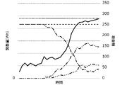
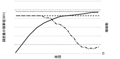
- FIG. 4 is a graph showing an example of demand adjustment control by the demand adjustment control system 100 according to the first embodiment when the electric power demand is tight.
- the vertical axis on the left side represents the adjustment amount per unit time
- the vertical axis on the right side represents the number of devices 20 executing the demand adjustment control
- the horizontal axis represents the time.
- the solid line represents the adjustment amount per unit time
- the broken line represents the number of the first devices 21 executing the demand adjustment control
- the dotted line represents the target adjustment amount.
- the target adjustment amount represents a positive value, that is, the amount of power saving.
- the alternate long and short dash line is the number of second devices 22 executing power saving control as demand adjustment control
- the alternate long and short dash line is the number of second devices 22 executing power increase control as demand adjustment control.
- the alternate long and short dash line represents the number of second devices 22 that are not performing demand adjustment control.
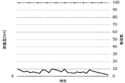
- FIG. 5 is a graph showing an example of demand adjustment control by the demand adjustment control system 100 according to the first embodiment when the fluctuation of the electric power demand is suppressed.
- the vertical axis on the left side represents the adjustment amount per unit time
- the vertical axis on the right side represents the number of devices 20 executing the demand adjustment control
- the horizontal axis represents the time.
- the solid line represents the adjustment amount per unit time
- the three-dot chain line represents the number of the second devices 22 that do not execute the demand adjustment control
- the dotted line represents the target adjustment amount.
- the target adjustment amount is zero in order to suppress fluctuations in power demand, that is, to maintain the current power demand.
- FIG. 5 the target adjustment amount is zero in order to suppress fluctuations in power demand, that is, to maintain the current power demand.
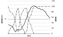
- FIG. 6 is a graph showing another example of demand adjustment control by the demand adjustment control system 100 according to the first embodiment when the fluctuation of the electric power demand is suppressed.
- the vertical axis on the left side represents the adjustment amount per unit time
- the vertical axis on the right side represents the number of devices 20 executing the demand adjustment control
- the horizontal axis represents the time.
- the solid line represents the adjustment amount per unit time
- the broken line represents the number of the first devices 21 executing the demand adjustment control
- the dotted line represents the target adjustment amount.
- the target adjustment amount is zero in order to suppress fluctuations in power demand, that is, to maintain the current power demand.
- the alternate long and short dash line is the number of second devices 22 executing power saving control as demand adjustment control
- the alternate long and short dash line is the number of second devices 22 executing power increase control as demand adjustment control.
- the alternate long and short dash line represents the number of second devices 22 that are not performing demand adjustment control.
- the adjustment amount per unit time is not within the range of the target adjustment amount, it is controlled so as to be within the range of the target adjustment amount.
- the number of the second devices 22 that execute the power saving control as the demand adjustment control and the power increase control that executes the power increase control as the demand adjustment control according to the fluctuation of the adjustment amount per unit time can both increase or decrease.
- the demand adjustment control system of the comparative example increases the number of devices 20 that perform demand adjustment control stepwise based on the integrated value of the adjustment amount during the implementation period of the demand adjustment request, and the demand adjustment control according to the first embodiment. Different from system 100. Further, in the demand adjustment control system of the comparative example, once the demand adjustment control of the device 20 is started during the demand adjustment request implementation period, the demand adjustment control of the device 20 is released until the demand adjustment request implementation period ends. This is different from the demand adjustment control system 100 according to the first embodiment. That is, the demand adjustment control system of the comparative example is different from the demand adjustment control system 100 according to the first embodiment in that the demand adjustment control is executed only for the first device 21 during the execution period of the demand adjustment request. It can be said that.
- FIG. 7 is a graph showing an example of demand adjustment control by the demand adjustment control system of the comparative example.
- the vertical axis on the left side represents the integrated value of the adjustment amount
- the vertical axis on the right side represents the number of devices 20 executing the demand adjustment control
- the horizontal axis represents the time.
- the solid line represents the integrated value of the adjustment amount
- the broken line represents the number of devices 20 executing the demand adjustment control
- the dotted line represents the target adjustment amount.
- the demand adjustment control system of the comparative example when the implementation period of the demand adjustment request is started, the demand adjustment control of the device group A is started first. Then, when the integrated value of the adjustment amount in the device group A reaches the first threshold value Th1, the demand adjustment control system of the comparative example further starts the demand adjustment control of the device group B. Then, when the integrated value of the adjustment amounts in the device group A and the device group B reaches the second threshold value Th2, the demand adjustment control system of the comparative example further starts the demand adjustment control of the device group C.
- the demand adjustment control is executed even though the integrated value of the adjustment amount in the device group A to the device group C exceeds the target adjustment amount during the execution period of the demand adjustment request.
- the number of devices 20 executing the demand adjustment control cannot be increased or decreased during the execution period of the demand adjustment request, and the integrated value of the adjustment amount is made to follow the target adjustment amount. There is a problem that it cannot be done.
- FIG. 8 is a graph showing an example of demand adjustment control by the demand adjustment control system 100 according to the first embodiment.
- the vertical axis on the left side represents the integrated value of the adjustment amount
- the vertical axis on the right side represents the number of devices 20 executing the demand adjustment control
- the horizontal axis represents the time.
- the solid line is the integrated value of the adjustment amount
- the broken line is the number of the first equipment 21 executing the demand adjustment control
- the alternate long and short dash line is the number of the second equipment 22 executing the demand adjustment control
- the dotted line Represents the target adjustment amount.
- the demand adjustment control system 100 when the implementation period of the demand adjustment request is started, the demand adjustment control of both the first device 21 and the second device 22 is started. .. Then, in the demand adjustment control system 100 according to the first embodiment, the demand adjustment control is continuously executed for the first device 21 and the demand adjustment control is executed for the second device 22 during the execution period of the demand adjustment request. The number of the second equipment 22 is appropriately increased or decreased.
- the demand adjustment control system 100 reduces the number of the second devices 22 executing the demand adjustment control as the integrated value of the adjustment amount approaches the target adjustment amount. .. Therefore, in the example shown in FIG. 8, the integrated value of the adjustment amount does not exceed the target adjustment amount during the execution period of the demand adjustment request. That is, in the demand adjustment control system 100 according to the first embodiment, the number of the second device 22 executing the demand adjustment control can be increased or decreased during the execution period of the demand adjustment request, so that the adjustment amount can be flexibly adjusted. There is an advantage that the integrated value of the adjustment amount can be easily made to follow the target adjustment amount.
- the target device 3 is determined from the device group 2 including the first device 21 and the second device 22 as described above. Therefore, in the demand adjustment control system 100 according to the first embodiment, even if the mode of the demand adjustment control of the second device 22 is repeatedly changed in order to adjust the adjustment amount during the implementation period of the demand adjustment request, the facility 4 The impact on users is relatively small. Therefore, the demand adjustment control system 100 according to the first embodiment has an advantage that the influence on the facility 4 at the time of requesting the demand adjustment can be easily reduced.
- FIG. 9 is a block diagram showing a configuration of the demand adjustment control system 100A according to the second embodiment.
- the demand adjustment control system 100A according to the second embodiment further includes a setting unit 16 that predicts a tendency of power consumption during the execution period of the demand adjustment request and sets an intermediate demand adjustment target value based on the predicted tendency. , It is different from the demand adjustment control system 100 according to the first embodiment. Further, in the demand adjustment control system 100A according to the second embodiment, the control unit 13 satisfies the intermediate demand adjustment target value during the implementation period so that the adjustment amount per unit time (for example, 1 minute) by the target device 3 is satisfied. It differs from the demand adjustment control system 100 according to the first embodiment in that the demand adjustment control of the target device 3 is executed.
- the integrated value of the adjustment amount falls within the range of the target adjustment amount during the execution period of the demand adjustment request, similarly to the demand adjustment control system 100 according to the first embodiment.
- Demand adjustment control of the target device 3 is executed so as to fit.
- the demand adjustment control system 100A according to the second embodiment controls the target device 3 so that the adjustment amount per unit time further satisfies the intermediate demand adjustment target value during the execution period of the demand adjustment request.
- FIGS. 10A and 10B are explanatory views of problems that may occur in the demand adjustment control by the demand adjustment control system 100 according to the first embodiment, respectively.
- the vertical axis on the left side is the adjustment amount per unit time
- the vertical axis on the right side is the number of facilities 4 performing demand adjustment control (in other words, the number of devices 20 performing demand adjustment control).
- the horizontal axis represents time.
- the solid line represents the adjustment amount per unit time
- the broken line represents the number of facilities 4 performing the demand adjustment control
- the dotted line represents the target adjustment amount per unit time.
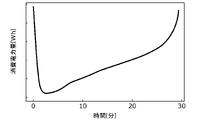
- the vertical axis represents the power consumption per unit time of each facility 4 as a whole
- the horizontal axis represents time.
- the demand adjustment control system 100 determines that the target adjustment amount per unit time will be exceeded if the current demand adjustment control is maintained, and the demand adjustment control is performed during the execution period of the demand adjustment request.
- the number of facilities 4 in other words, the second device 22) that implements the above is reduced.
- the power consumption per unit time in each facility 4 may temporarily increase during the implementation period of the demand adjustment request.
- Such an event can occur, for example, when the facility 4 is a store that handles food, due to the defrosting of the freezing equipment. Further, such an event may occur, for example, due to an increase or decrease in the load of the air conditioning equipment due to a change in the outside air temperature.
- the power consumption per unit time of each facility 4 increases in this way, the adjustment amount per unit time relatively decreases.
- the power consumption per unit time of each facility 4 as a whole rises sharply in the latter half of the implementation period of the demand adjustment request.
- the adjustment amount per unit time decreases in the latter half of the implementation period of the demand adjustment request, and the adjustment amount per unit time does not reach the target adjustment amount per unit time. There is a problem.
- the setting unit 16 estimates the tendency of power consumption during the implementation period of the demand adjustment request.
- the tendency of power consumption can be estimated by using a model learned to output the tendency of power consumption by inputting, for example, the history of power consumption for each facility 4 in the past or the history of outside air temperature. Is.
- the setting unit 16 calculates and sets the intermediate demand adjustment target value based on the estimated tendency of power consumption. For example, suppose that it was estimated that power consumption was relatively low in the first half of the demand adjustment request implementation period, while power consumption tended to increase in the second half. In this case, the setting unit 16 sets the intermediate demand adjustment target value so as to temporarily exceed the target adjustment amount per unit time in preparation for the increase in power consumption in the latter half of the execution period of the demand adjustment request. .. Then, the control unit 13 executes the demand adjustment control of the target device 3 so that the adjustment amount per unit time by the target device 3 follows the intermediate demand adjustment target value during the execution period of the demand adjustment request.
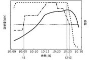
- FIG. 11 is a graph showing an example of the result of the demand adjustment control by the demand adjustment control system 100A according to the second embodiment.
- the vertical axis on the left side is the adjustment amount per unit time
- the vertical axis on the right side is the number of facilities 4 performing demand adjustment control (in other words, the number of devices 20 performing demand adjustment control).
- the horizontal axis represents time.
- the solid line indicates the adjustment amount per unit time
- the broken line indicates the number of facilities 4 performing the demand adjustment control
- the alternate long and short dash line indicates the intermediate demand adjustment target value
- the dotted line indicates the target adjustment amount per unit time. ing.
- the setting unit 16 estimates that the power consumption per unit time of each facility 4 as a whole increases in the latter half of the execution period of the demand adjustment request. Therefore, the setting unit 16 sets the intermediate demand adjustment target value so that it temporarily becomes larger than the target adjustment amount per unit time in the period from the time t1 to the time t2. Therefore, in the example shown in FIG. 11, the control unit 13 executes the demand adjustment control until the time t3 even if the adjustment amount per unit time exceeds the target adjustment amount per unit time. In other words, the number of second devices 22) is maintained without being reduced.
- the adjustment amount per unit time finally satisfies the target adjustment amount per unit time during the implementation period of the demand adjustment request.
- the demand adjustment control system 100A according to the second embodiment it is easy to avoid the situation where the adjustment amount per unit time does not satisfy the target adjustment amount per unit time during the implementation period of the demand adjustment request. There is an advantage.
- the luminaire is the first device 21, but not all the luminaires need to be the first device 21, and some luminaires are the second device 22 depending on the time zone. It may be classified into. That is, depending on the conditions, the first device 21 may be classified into the second device 22, and the second device 22 may be classified into the first device 21.
- the demand adjustment control system 100 determines the device 20 included in the device group 2 as either the first device 21 or the second device 22. 17 may be further provided.
- FIG. 12 is a block diagram showing the configuration of the demand adjustment control system 100 according to the modified example of the first embodiment.
- the type determination unit 17 determines the device 20 included in the device group 2 as either the first device 21 or the second device 22 based on, for example, the season or the time zone. Specifically, when the facility 4 is, for example, a convenience store or the like and has a kitchen, the type determination unit 17 determines the flyer installed in the kitchen as the second device 22 only in the summer, and the second device 22 in other seasons. It may be determined as one device 21.
- the type determination unit 17 may determine the device 20 included in the device group 2 as either the first device 21 or the second device 22 based on the past results of demand adjustment control.
- the type determination unit 17 may be provided in the demand adjustment control system 100A according to the second embodiment.
- the control unit 13 executes the demand adjustment control of the second device 22 without depending on the facility 4, but this is limited to this. I can't.
- the control unit 13 may execute the demand adjustment control of the second device 22 under the conditions according to the facility 4 in which the second device 22 is installed. ..
- the control unit 13 may change the content of the demand adjustment control of the second device 22 according to the area where the facility 4 is located.
- control unit 13 executes demand adjustment control for the air conditioning equipment as the second equipment 22 in winter, if the facility 4 in which the second equipment 22 is installed is in a cold region, the air conditioning equipment Demand adjustment control is executed to lower the set temperature of. On the other hand, the control unit 13 executes the demand adjustment control of stopping the operation of the air conditioning equipment if the facility 4 in which the second equipment 22 is installed is not in a cold region.
- the control unit 13 may sequentially execute the demand adjustment control of the plurality of second devices 22.
- the target device 3 includes three second devices 22 and are “A”, “B”, and “C”, respectively.
- the control unit 13 executes the demand adjustment control of "A”, then the demand adjustment control of "B”, and then executes the demand adjustment control of "C”.
- the control unit 13 controls so that the demand adjustment control of each of the plurality of second devices 22 is not performed at the same time.
- the determination unit 12 determines the second device 22 to be included in the target device 3 based on the past results of demand adjustment control, but the present invention is not limited to this.
- the determination unit 12 may randomly determine the second device 22 to be included in the target device 3 from the plurality of second devices 22 that can participate in the demand adjustment control.
- the determination unit 12 assigns consecutive numbers to each of the plurality of second devices 22, and the second device is numbered to match the pseudo-random numbers generated by an appropriate pseudo-random number algorithm. 22 is included in the target device 3.
- the demand adjustment control systems 100 and 100A are realized as a single device, but may be realized by a plurality of devices.
- the components included in the demand adjustment control system 100, 100A may be distributed to the plurality of devices in any way.
- the present disclosure may be realized by cloud computing or edge computing.
- all or a part of the components of the demand adjustment control systems 100 and 100A in the present disclosure may be configured by dedicated hardware, or software suitable for each component. It may be realized by executing a program. Even if each component is realized by a program execution unit such as a CPU (Central Processing Unit) or a processor reading and executing a software program recorded on a recording medium such as an HDD (Hard Disk Drive) or a semiconductor memory. good.
- a program execution unit such as a CPU (Central Processing Unit) or a processor reading and executing a software program recorded on a recording medium such as an HDD (Hard Disk Drive) or a semiconductor memory. good.
- the component of the demand adjustment control system 100 in the present disclosure may be composed of one or a plurality of electronic circuits.
- the one or more electronic circuits may be general-purpose circuits or dedicated circuits, respectively.
- One or more electronic circuits may include, for example, a semiconductor device, an IC (Integrated Circuit), an LSI (Large Scale Integration), or the like.
- the IC or LSI may be integrated on one chip or may be integrated on a plurality of chips. Here, it is called IC or LSI, but the name changes depending on the degree of integration, and it may be called system LSI, VLSI (Very Large Scale Integration), or ULSI (Ultra Large Scale Integration).
- an FPGA Field Programmable Gate Array programmed after manufacturing the LSI can also be used for the same purpose.
- the general or specific aspects of the present disclosure may be realized by a system, an apparatus, a method, an integrated circuit or a computer program.
- it may be realized by a computer-readable non-temporary recording medium such as an optical disk, HDD or semiconductor memory in which the computer program is stored.
- the present disclosure may be realized as a program for executing the demand adjustment control method in the above embodiment by a computer.
- this program may be recorded on a non-temporary recording medium such as a computer-readable CD-ROM, or may be distributed on a communication path such as the Internet.
- the demand adjustment control systems 100 and 100A include an acquisition unit 11, a determination unit 12, and a control unit 13.
- the acquisition unit 11 acquires the target adjustment amount based on the temporary demand adjustment request.
- the determination unit 12 determines the target device 3 to be subject to the demand adjustment control from the device group 2 installed in the facility 4 based on the target adjustment amount acquired by the acquisition unit 11.
- the control unit 13 executes the demand adjustment control of the target device 3 so that the adjustment amount by the target device 3 falls within the range of the target adjustment amount during the execution period of the demand adjustment request.
- the device group 2 includes a first device 21 in which the mode of demand adjustment control is not changed during the implementation period, and a second device 22 in which the mode of demand adjustment control can be changed during the implementation period.
- the influence on the user of the facility 4 can be relatively small. Therefore, there is an advantage that the influence on the facility 4 at the time of requesting the demand adjustment can be easily reduced.
- the determination unit 12 determines the second device 22 to be included in the target device 3 based on the past results of demand adjustment control.
- the second device 22 that can easily secure the adjustment amount can be included in the target device 3 during the implementation period of the demand adjustment request, there is an advantage that the adjustment amount can be easily adjusted.
- the demand adjustment control systems 100 and 100A further include a question unit 14 asking the facility 4 whether or not to participate in the demand adjustment control.
- the determination unit 12 determines the target device 3 in response to the response to the inquiry by the question unit 14.
- the demand adjustment control system 100A further includes a setting unit 16 that predicts a tendency of power consumption during the implementation period and sets an intermediate demand adjustment target value based on the predicted tendency.
- the control unit 13 executes the demand adjustment control of the target device 3 so that the adjustment amount per unit time by the target device 3 satisfies the intermediate demand adjustment target value during the implementation period.
- the demand adjustment control systems 100 and 100A further include a type determination unit 17 that determines the device 20 included in the device group 2 as either the first device 21 or the second device 22.
- the control unit 13 executes the demand adjustment control of the second device 22 under the conditions according to the facility 4 in which the second device 22 is installed.
- control unit 13 sequentially executes demand adjustment control of the plurality of second devices 22.
- the demand adjustment control method includes acquisition step ST1, determination step ST2, and control step ST3.
- acquisition step ST1 the target adjustment amount based on the temporary demand adjustment request is acquired.
- determination step ST2 the target device 3 to be subject to the demand adjustment control is determined from the device group 2 installed in the facility 4 based on the target adjustment amount acquired in the acquisition step ST1.
- control step ST3 the demand adjustment control of the target device 3 is executed so that the adjustment amount by the target device 3 falls within the range of the target adjustment amount during the execution period of the demand adjustment request.
- the device group 2 includes a first device 21 in which the mode of demand adjustment control is not changed during the implementation period, and a second device 22 in which the mode of demand adjustment control can be changed during the implementation period.
- the influence on the user of the facility 4 can be relatively small. Therefore, there is an advantage that the influence on the facility 4 at the time of requesting the demand adjustment can be easily reduced.
- the program according to the embodiment causes the processor to execute the above-mentioned demand adjustment control method.
- the influence on the user of the facility 4 can be relatively small. Therefore, there is an advantage that the influence on the facility 4 at the time of requesting the demand adjustment can be easily reduced.
- the present disclosure is applicable to a demand adjustment control system or the like that executes demand adjustment control for a large number of devices included in a large number of facilities such as a convenience store.
Landscapes
- Engineering & Computer Science (AREA)
- Power Engineering (AREA)
- Physics & Mathematics (AREA)
- General Physics & Mathematics (AREA)
- Business, Economics & Management (AREA)
- Automation & Control Theory (AREA)
- Health & Medical Sciences (AREA)
- Economics (AREA)
- Public Health (AREA)
- Marketing (AREA)
- Primary Health Care (AREA)
- Strategic Management (AREA)
- Tourism & Hospitality (AREA)
- Human Resources & Organizations (AREA)
- General Business, Economics & Management (AREA)
- General Health & Medical Sciences (AREA)
- Theoretical Computer Science (AREA)
- Water Supply & Treatment (AREA)
- Supply And Distribution Of Alternating Current (AREA)
- Remote Monitoring And Control Of Power-Distribution Networks (AREA)
- Management, Administration, Business Operations System, And Electronic Commerce (AREA)
Abstract
需要調整制御システム(100)は、取得部(11)と、決定部(12)と、制御部(13)と、を備える。取得部(11)は、一時的な需要調整要請に基づく目標調整量を取得する。決定部(12)は、施設(4)に設置された機器群(2)から、取得部(11)が取得した目標調整量に基づいて需要調整制御の対象となる対象機器(3)を決定する。制御部(13)は、需要調整要請の実施期間において、対象機器(3)による調整量が目標調整量の範囲に収まるように、対象機器(3)の需要調整制御を実行する。機器群(2)は、実施期間において需要調整制御の態様が変更されない第1機器(21)と、実施期間において需要調整制御の態様を変更可能な第2機器(22)と、を含む。
Description
本開示は、需要調整要請時に需要調整するように機器を制御する需要調整制御システム、需要調整制御方法、及びプログラムに関する。
特許文献1には、節電制御用の電子装置が開示されている。この電子装置は、送受信器と、データ解析ブロックと、表示制御ブロックと、節電発動ライン制御ブロックと、指令信号出力ブロックと、を備える。送受信器は、電力供給管理システムから提供される時間帯毎の電力使用量実績データ及び電力使用量予測データを取得する。データ解析ブロックは、電力使用量実績データ及び電力使用量予測データの変化を解析し、解析結果を表示するグラフのデータを作成する。表示制御ブロックは、表示器にグラフを表示するととともに、グラフ上で節電発動設定ラインを表示する。
節電発動ライン制御ブロックは、節電発動設定ラインを調整し、任意の位置で決定し、決定された位置の値を節電発動用値とする。そして、指令信号出力ブロックは、電力使用量実績データ及び/又は電力使用量予測データの値が節電発動用値を越える場合、節電対象である装置へ、節電指令信号を出力する。
本開示は、需要調整要請時における施設への影響を低減しやすい需要調整制御システム等を提供する。
本開示の一態様に係る需要調整制御システムは、取得部と、決定部と、制御部と、を備える。前記取得部は、一時的な需要調整要請に基づく目標調整量を取得する。前記決定部は、施設に設置された機器群から、前記取得部が取得した前記目標調整量に基づいて需要調整制御の対象となる対象機器を決定する。前記制御部は、前記需要調整要請の実施期間において、前記対象機器による調整量が前記目標調整量の範囲に収まるように、前記対象機器の需要調整制御を実行する。前記機器群は、前記実施期間において需要調整制御の態様が変更されない第1機器と、前記実施期間において需要調整制御の態様を変更可能な第2機器と、を含む。
本開示の一態様に係る需要調整制御方法は、取得ステップと、決定ステップと、制御ステップと、を含む。前記取得ステップでは、一時的な需要調整要請に基づく目標調整量を取得する。前記決定ステップでは、施設に設置された機器群から、前記取得ステップで取得した前記目標調整量に基づいて需要調整制御の対象となる対象機器を決定する。前記制御ステップでは、前記需要調整要請の実施期間において、前記対象機器による調整量が前記目標調整量の範囲に収まるように、前記対象機器の需要調整制御を実行する。前記機器群は、前記実施期間において需要調整制御の態様が変更されない第1機器と、前記実施期間において需要調整制御の態様を変更可能な第2機器と、を含む。
本開示の一態様に係るプログラムは、プロセッサに、前記需要調整制御方法を実行させる。
本開示における需要調整制御システム等によれば、需要調整要請時における施設への影響を低減しやすい、という利点がある。
(本開示の基礎となった知見)
まず、発明者の着眼点が、下記に説明される。
まず、発明者の着眼点が、下記に説明される。
従来、例えば電力会社からのDR(Demand Response)等の節電要請があった場合、節電対象の機器の動作を停止させたり、節電対象の機器の動作モードを変更させたりすることで、節電要請に応じた節電制御を行っていた。
近年では、例えばVPP(Virtual Power Plant)等において、単に節電要請に応じて節電対象の機器を節電制御するだけでは足りず、節電要請時に指令される調整量の範囲に収まるように節電対象の機器を節電制御することが望まれる。また、VPP等においては、電力会社等が供給する電圧の大きさ及び周波数を一定とするために電力の需要及び需給を常に一致させるべく同時同量を達成することが原則であり、節電要請だけでなく、電力の過剰生成分を消費させるための増電要請がなされる場合がある。このため、増電要請時に指令される増電量の範囲に収まるように増電対象の機器を増電制御することも望まれる。つまり、節電及び増電といった需要調整要請に応じて需要調整対象の機器を需要調整制御することが望まれる。
しかしながら、従来では、例えば需要調整要請が節電要請である場合に、一度、節電要請に応じて節電対象の機器の節電制御を実行すると、節電要請が解除されるまで節電制御も解除されない。このため、従来では、上述のように需要調整要請(節電要請)により指令された調整量(節電量)の範囲に収まるように需要調整(節電)対象の機器を柔軟に制御することが難しい、という問題がある。
また、仮に上述のように需要調整(節電)対象の機器を柔軟に制御できたとしても、更に以下のような問題が生じ得る。すなわち、需要調整要請(節電要請)により指令された調整量(節電量)の範囲に収まるように、需要調整(節電)対象の機器の動作を繰り返し変更することにより、需要調整(節電)対象の機器が設置された施設に対して影響を及ぼし得る。
例えば、施設がコンビニエンスストア等の店舗であって、節電対象の機器が売場に設置された照明器具である、と仮定する。この場合、例えば節電要請に応じて照明器具の調光率の増減を繰り返すと、店舗の照明環境の変化を客が視覚的に感知することにより、客が不快感を覚える可能性がある。
以上を鑑み、発明者は本開示を創作するに至った。
以下、適宜図面を参照しながら、実施の形態を詳細に説明する。但し、必要以上に詳細な説明は省略する場合がある。例えば、既によく知られた事項の詳細説明や実質的に同一の構成に対する重複説明を省略する場合がある。これは、以下の説明が不必要に冗長になるのを避け、当業者の理解を容易にするためである。
また、以下では、所定の数値(例えば、後述する調整量の積算値等)と閾値(例えば、後述する目標調整量等)とを比較しているが、比較においては、一方の分岐条件に閾値が含まれてもよいし、他方の分岐条件に閾値が含まれてもよい。例えば、一方の分岐条件は、「所定の数値が閾値以上(又は以下)である」ことであってもよいし、「所定の数値が閾値を上回る(又は下回る)」ことであってもよい。
なお、発明者は、当業者が本開示を十分に理解するために添付図面及び以下の説明を提供するのであって、これらによって請求の範囲に記載の主題を限定することを意図するものではない。
(実施の形態1)
[1-1.全体構成]
まず、実施の形態1に係る需要調整制御システム100を含む全体構成について図1を用いて説明する。図1は、実施の形態1に係る需要調整制御システム100を含む全体構成を示すブロック図である。需要調整制御システム100は、例えば電力会社又はアグリゲータ等が運用する外部システム7からの需要調整要請に応じて、機器群2から需要調整制御の対象となる対象機器3を決定し、対象機器3の需要調整制御を実行するためのシステムである。なお、対象機器3の需要調整制御には、例えば需要調整制御が不要であるという需要調整要請である場合に、対象機器3を意図的に制御しないことも含まれ得る。例えば、需要調整要請によっては、需要調整制御を実行する対象機器3の数が零となることもあり得るが、このような場合も対象機器3の需要調整制御に含まれ得る。
需要調整要請は、恒久的な要請ではなく、例えば上述のDR等のように一時的な要請である。また、需要調整要請は、上述のDRの他に、電力需要のピークにあたる時間帯の電力消費を低く抑えるためのピークカットを含み得る。また、需要調整要請は、電力需給市場における電力価格に基づいて、電力価格が比較的高い時間帯の電力消費を低く抑えるための要請を含み得る。
機器群2は、需要調整制御の対象となり得る施設4に設置された機器20を含んでいる。例えば、施設4が1つである場合、機器群2は、当該施設4に設置された機器20を含む。また、例えば、施設4が複数である場合、機器群2は、複数の施設4の各々に設置された全ての機器20を含む。
施設4は、例えばコンビニエンスストア又はスーパーマーケット等の店舗を含む。なお、施設4は、店舗に限らず、例えば戸建て住宅又は集合住宅等の住宅施設であってもよいし、オフィス、学校、福祉施設、病院及び工場等の非住宅の施設も含み得る。実施の形態1では、施設4は、特に断りのない限り、コンビニエンスストアである、と仮定する。
実施の形態1では、図2に示すように、需要調整制御システム100の制御対象となる施設4は複数である、と仮定する。図2は、実施の形態1に係る需要調整制御システム100による需要調整制御の一例を示す概要図である。図2に示す例では、各施設4には複数の機器20が設置されている。図2に示す例では、機器群2は、第1機器21(図中△印が付された機器20)と、第2機器22(図中〇印が付された機器20)と、第3機器23(図中×印が付された機器20)と、を含んでいる。詳しくは後述するが、機器群2のうち対象機器3となり得る機器20は、第1機器21及び第2機器22である。一方、機器群2のうち対象機器3になり得ない機器20は、第3機器23である。図2に示す例では、各施設4の全ての第1機器21及び第2機器22が対象機器3である。
[1-2.需要調整制御システム]
次に、需要調整制御システム100の詳細について説明する。需要調整制御システム100は、図1に示すように、取得部11と、決定部12と、制御部13と、質問部14と、記憶部15と、を備えている。なお、実施の形態1において、需要調整制御システム100は、取得部11と、決定部12と、制御部13とを少なくとも備えていればよく、その他の構成要素は備えていなくてもよい。例えば、上記のその他の構成要素については、需要調整制御システム100とは別のシステム等により実現可能である。
次に、需要調整制御システム100の詳細について説明する。需要調整制御システム100は、図1に示すように、取得部11と、決定部12と、制御部13と、質問部14と、記憶部15と、を備えている。なお、実施の形態1において、需要調整制御システム100は、取得部11と、決定部12と、制御部13とを少なくとも備えていればよく、その他の構成要素は備えていなくてもよい。例えば、上記のその他の構成要素については、需要調整制御システム100とは別のシステム等により実現可能である。
実施の形態1では、需要調整制御システム100は、サーバ10により実現される。サーバ10は、例えばインターネット等のネットワークN1を介して、各施設4との間で通信可能である。また、サーバ10は、ネットワークN1を介して、外部システム7との間でも通信可能である。サーバ10と各施設4との間、及びサーバ10と外部システム7との間の通信は、例えば無線通信であって、その通信規格は特に限定されない。なお、サーバ10と各施設4との間、及びサーバ10と外部システム7との間の通信は、有線通信であってもよい。
サーバ10は、プロセッサ及びメモリを有しており、プロセッサにてメモリに記憶されているコンピュータプログラムを実行することにより、各種機能を実現する。実施の形態1では、メモリは、記憶部15である。
取得部11は、一時的な需要調整要請に基づく目標調整量を取得する。ここで、目標調整量は、需要調整要請の実施期間において需要調整される電力量の積算値の目標値をいう。実施の形態1では、取得部11は、外部システム7から需要調整要請を受信する際に併せて受信する調整量の指令値を目標調整量として取得する。需要調整制御に参加可能な機器20の数は、後述する質問部14による問い合わせに対する各施設4からの回答により得られる。
なお、実施の形態では、節電時において調整量が正の値となり、増電時において調整量が負の値となることとして説明する。つまり、目標調整量が正の値である場合、需要調整要請は節電要請に相当し、目標調整量が負の値である場合、需要調整要請は増電要請に相当する。
決定部12は、施設4に設置された機器群2から、取得部11が取得した目標調整量に基づいて需要調整制御の対象となる対象機器3を決定する。実施の形態1では、決定部12は、質問部14による問い合わせに対する回答に応じて、対象機器3を決定する。既に述べたように、上記回答には、需要調整制御に参加可能な機器20に関する情報が含まれている。したがって、決定部12は、需要調整制御に参加可能な機器20の中から、対象機器3を決定する。
機器群2は、第1機器21と、第2機器22と、を含む。実施の形態1では、各施設4に第1機器21と、第2機器22と、が設置されている、と仮定する。なお、複数の施設4が存在する場合に、第1機器21が設置されていない施設4が存在していてもよいし、第2機器22が設置されていない施設4が存在していてもよい。
第1機器21又は第2機器22が照明器具である場合、照度を抑えるように調光する等の節電制御(需要調整制御)、又は照度を上げるように調光する等の増電制御(需要調整制御)が実行され得る。また、第1機器21又は第2機器22がエアーコンディショナ等の空調機器である場合、冷房運転時においては設定温度を上げる、暖房運転時においては設定温度を下げる、風量を下げる、ドライ運転時においては冷房運転に切り替える、又は電源を切る等の節電制御(需要調整制御)が実行され得る。また、冷房運転時においては設定温度を下げる、暖房運転時においては設定温度を上げる、風量を上げる、冷房運転時においてはドライ運転に切り替える、又は電源を入れる等の増電制御(需要調整制御)が実行され得る。また、第1機器21又は第2機器22が冷蔵設備又は冷凍設備等の要冷設備である場合、庫内温度を上昇させる等の節電制御(需要調整制御)、又は庫内温度を下降させる等の増電制御(需要調整制御)が実行され得る。
第1機器21は、需要調整要請の実施期間において需要調整制御の態様が変更されない機器である。例えば、第1機器21が照明器具であって、照度を抑えるように調光するという節電制御(需要調整制御)が実行される、と仮定する。この場合、照明器具は、一度調光すると、節電要請(需要調整要請)の実施期間においては照度を元に戻す制御を実行することがない。第1機器21は、需要調整要請の実施期間において需要調整制御の態様が変更されることで、施設4の利用者に影響を及ぼし得る機器である。例えば、照明器具は、需要調整要請の実施期間において調光率の増減を繰り返すことで、施設4の照明環境が変化し、施設4の利用者に視覚的な影響を及ぼし得る。
第2機器22は、需要調整要請の実施期間において需要調整制御の態様が変更可能な機器である。例えば、第2機器22が空調機器であって、風量を弱めるという節電制御(需要調整制御)が実行される、と仮定する。この場合、空調機器は、節電要請(需要調整要請)の実施期間において、風量を元に戻す制御を実行してもよい。第2機器22は、需要調整要請の実施期間において需要調整制御の態様が変更されても、施設4の利用者に与える影響が比較的小さい機器である。例えば、空調機器は、需要調整要請の実施期間において風量の強弱を変更する制御を繰り返したとしても、施設4の温度変化は施設4の利用者に知覚されがたく、施設4の利用者に影響を及ぼしにくい。
また、例えば、第2機器22が冷蔵設備又は冷凍設備等の要冷設備であって、庫内温度を上昇させるという節電制御(需要調整制御)が実行される、と仮定する。この場合、要冷設備は、節電要請(需要調整要請)の実施期間において、庫内温度を元に戻す制御を実行してもよい。つまり、要冷設備は、需要調整要請の実施期間において庫内温度の増減を変更する制御を繰り返したとしても、庫内温度の変化は施設4の利用者に知覚されがたく、施設4の利用者に影響を及ぼしにくい。
以下、第1機器21及び第2機器22の具体例について列挙する。施設4が例えばコンビニエンスストア等の食品を取り扱う店舗である場合、第1機器21は、事務室若しくは売場に設置された照明器具、又は厨房に設置された換気扇等を含み得る。また、施設4が例えばオフィスである場合、第1機器21は、照明器具、又は換気設備等を含み得る。
施設4が例えばコンビニエンスストア等の食品を取り扱う店舗である場合、第2機器22は、例えば蓄電装置、事務所若しくは売場に設置された空調機器、ドリンクウォーマー、フライヤー、冷蔵機器、又は冷凍機器を含み得る。また、施設4が例えばオフィスである場合、第2機器22は、空調機器等を含み得る。
なお、機器群2には、第1機器21及び第2機器22以外の機器も含まれ得る。つまり、機器群2には、需要調整制御の対象とならない第3機器23が含まれ得る。第3機器23は、需要調整要請の実施期間において需要調整制御されるだけでも、施設4の利用者に影響を及ぼし得る機器である。例えば、施設4がコンビニエンスストア等の食品を取り扱う店舗である場合、調理済み食品(例えば、おでん等)のウォーマー、コーヒーマシン、又は電子レンジ等は第3機器23である。つまり、第3機器23は、需要調整制御を実行することにより、施設4の利用者が利用できなくなるという、施設4の運用等に大きな影響を及ぼし得る機器であるため、需要調整制御の対象から除外される。
実施の形態1では、決定部12は、過去の需要調整制御の実績に基づいて、対象機器3に含める第2機器22を決定する。具体的には、決定部12は、過去の需要調整制御の実績に基づいて、需要調整制御に参加可能な複数の第2機器22にそれぞれ優先度を設定する。例えば、決定部12は、需要調整要請の実施期間において期待できる調整量が大きい第2機器22に対して、高い優先度を設定する。また、例えば、決定部12は、過去の需要調整制御への参加率が高い第2機器22に対して、高い優先度を設定する。そして、決定部12は、優先度の高い第2機器22から順に、第2機器22を対象機器3に含める。
また、決定部12は、需要調整制御に参加可能な全ての第2機器22を対象機器3に含めなくてもよい。この場合、仮に需要調整要請の実施期間の途中において、節電量(調整量)の指令値に対して節電量(調整量)に不足が生じれば、決定部12にて最初に対象機器3に含めた第2機器22以外の第2機器22を、更に対象機器3に含めてもよい。一例として、需要調整要請の実施期間の途中において、節電量(調整量)の指令値に対して節電量(調整量)に不足が生じた場合に、決定部12にて最初に決定した施設4以外の施設4の第2機器22を、更に対象機器3に含めてもよい。この場合、追加の施設4は、需要調整制御に参加可能な施設4である。
なお、決定部12は、例えば需要調整制御システム100の管理者等の操作入力に応じて、対象機器3に含める第2機器22を決定してもよい。
制御部13は、需要調整要請の実施期間において、対象機器3による調整量が目標調整量の範囲に収まるように、対象機器3の需要調整制御を実行する。実施の形態1では、制御部13は、対象機器3に対して需要調整制御の指令を含む制御信号を送信することにより、対象機器3を制御する。各対象機器3は、制御信号を受信すると、制御信号に含まれる需要調整制御の指令に従って需要調整制御を実行する。
具体的には、制御部13は、需要調整要請の実施期間が開始されると、対象機器3に対して制御信号を送信する。また、制御部13は、需要調整要請の実施期間中において、対象機器3による調整量が目標調整量の範囲を逸脱しそうな場合、対象機器3のうち第2機器22に対して更に制御信号を送信する。当該制御信号は、需要調整制御の態様を変更する指令を含む。
実施の形態1では、制御部13は、各施設4に設置されたスマートメータ等の電力量計5から定期的に送信される電力情報を取得し、取得した電力情報に基づいて対象機器3による調整量の積算値と目標調整量とを比較する。電力情報は、例えば各施設4で消費される電力量である。制御部13は、各施設4からの電力情報に基づいて、調整量を算出する。そして、制御部13は、例えば調整量の積算値が目標調整量を超過しそうな場合、調整量の積算値と目標調整量との差分に応じて、需要調整制御を実行している第2機器22の動作を停止させたり、需要調整制御を実行している第2機器22の需要調整制御を解除したりする。なお、「調整量の積算値が目標調整量を超過する」とは、目標調整量が正の値(つまり、節電量)である場合には積算値が目標調整量を上回ることに相当し、目標調整量が負の値(つまり、増電量)である場合には積算値が目標調整量を下回ることに相当する。
第1機器21は、需要調整要請の実施期間の開始時に制御信号を受信すると、制御信号に含まれる需要調整制御の指令に従って需要調整制御を実行する。そして、第1機器21は、需要調整要請の実施期間が終了するまでの間、需要調整制御の態様を変更しない。
一方、第2機器22は、需要調整要請の実施期間の開始時に制御信号を受信すると、制御信号に含まれる需要調整制御の指令に従って需要調整制御を実行する。そして、第2機器22は、需要調整要請の実施期間中において更に制御信号を受信した場合、当該制御信号の指令に従って需要調整制御の態様を変更する。
なお、需要調整要請が節電要請である場合、節電要請の実施期間において第2機器22は節電制御のみを実行するとは限らず、途中で増電制御を実行する場合もあり得る。また、需要調整要請が増電要請である場合、増電要請の実施期間において第2機器22は増電制御のみを実行するとは限らず、途中で節電制御を実行する場合もあり得る。
質問部14は、施設4に対して需要調整制御への参加の有無を問い合わせる。実施の形態1では、質問部14は、需要調整要請を受信したことの通知、及び需要調整制御に参加可能な機器20(第1機器21及び第2機器22)に関する情報を要求する指令を含む質問信号を、各施設4に向けて送信する。なお、質問部14は、例えば施設4のある地域、又は施設4の立地条件等に応じて、質問信号の送信対象の施設4を制限してもよい。つまり、質問部14は、全ての施設4に対して質問信号を送信するのではなく、一部の施設4のみに対して質問信号を送信してもよい。
各施設4では、例えばタブレット端末、又はパーソナルコンピュータ等の情報端末6にて質問信号を受信する。質問信号を受信した情報端末6は、需要調整制御に参加可能な機器20に関する情報を含む応答信号を、需要調整制御システム100に向けて返信する。ここで、需要調整制御に参加可能な機器20の設定については、情報端末6が質問信号を受信した時点で、施設4の管理者等が情報端末6を操作して行ってもよいし、質問信号を受信する前に事前に行ってもよい。また、応答信号の返信は、施設4の管理者等の操作に応じて行われてもよいし、自動的に行われてもよい。
なお、需要調整制御に参加可能な機器20の設定においては、需要調整要請の実施期間において需要調整制御への参加からの除外を希望する時間帯を設定してもよい。例えば、需要調整要請の実施期間が午後1時~午後2時である、と仮定する。この場合、上記時間帯として午後1時半~午後2時までの時間を設定してもよい。
記憶部15は、サーバ10のプロセッサが各種制御を行うために必要な情報(コンピュータプログラム等)が記憶される記憶装置である。記憶部15は、例えば半導体メモリにより実現されるが、特に限定されることなく公知の電子情報記憶の手段を用いることができる。記憶部15には、例えば需要調整要請の実施期間において需要調整制御に参加可能な機器20に関するデータ等が記憶される。
[2.動作]
以上のように構成された需要調整制御システム100の動作について、以下図3を用いて説明する。図3は、実施の形態1に係る需要調整制御システム100の動作例を示すフローチャートである。以下では、需要調整制御システム100は、外部システム7から需要調整要請としてDRを受信する、と仮定する。もちろん、以下の動作は、外部システム7からDR以外の需要調整要請を受信する場合にも実行される。また、以下では、決定部12が決定する対象機器3には、第1機器21と、第2機器22とが含まれている、と仮定する。
以上のように構成された需要調整制御システム100の動作について、以下図3を用いて説明する。図3は、実施の形態1に係る需要調整制御システム100の動作例を示すフローチャートである。以下では、需要調整制御システム100は、外部システム7から需要調整要請としてDRを受信する、と仮定する。もちろん、以下の動作は、外部システム7からDR以外の需要調整要請を受信する場合にも実行される。また、以下では、決定部12が決定する対象機器3には、第1機器21と、第2機器22とが含まれている、と仮定する。
まず、取得部11は、外部システム7からの需要調整要請を受信する(S1)。このとき、取得部11は、需要調整要請と共に調整量の指令値(つまり、目標調整量)も併せて受信する。処理S1は、需要調整制御方法の取得ステップST1に相当する。
取得部11が需要調整要請を受信した後、質問部14は、各施設4に向けて質問信号を送信することにより、各施設4に対して需要調整制御への参加の有無を問い合わせる(S2)。なお、例えば需要調整要請を受信した時点より前の所定期間(例えば、1日)において、既に各施設4から問い合わせに対する回答を得ている場合、処理S2は省略してもよい。
次に、決定部12は、取得部11が取得した目標調整量に基づいて、需要調整制御に参加可能な機器20の中から対象機器3を決定する(S3)。処理S3においては、既に述べたように、決定部12は、優先度の高い第2機器22から順に、第2機器22を対象機器3に含める。処理S3は、需要調整制御方法の決定ステップST2に相当する。
次に、制御部13は、需要調整要請の実施期間が開始されると、対象機器3に対して制御信号を送信することにより、対象機器3の需要調整制御を開始する(S4)。その後、制御部13は、各施設4に設置された電力量計5から定期的に電力情報を取得し(S5)、取得した電力情報に基づいて対象機器3による調整量の積算値と目標調整量とを比較する(S6)。
調整量の積算値が目標調整量を超過しそうな場合(S6:Yes)、制御部13は、調整量の積算値と目標調整量との差分に応じて、需要調整制御を実行している第2機器22の需要調整制御の態様を変更する(S7)。一方、調整量の積算値が目標調整量を超過しそうにない場合(S6:No)、制御部13は、需要調整制御を実行している第2機器22の需要調整制御を維持する(S8)。
その後、需要調整要請の実施期間が終了するまでの間(S9:No)、制御部13は、上記の一連の処理S5~S8を繰り返す。そして、需要調整要請の実施期間が終了すると(S9:Yes)、制御部13は、対象機器3による需要調整制御を解除する(S10)。処理S4~S10は、需要調整制御方法の制御ステップST3に相当する。
以下、実施の形態1に係る需要調整制御システム100による需要調整制御の一例について説明する。図4は、電力需要の逼迫時における実施の形態1に係る需要調整制御システム100による需要調整制御の一例を示すグラフである。図4では、左側の縦軸は単位時間当たりの調整量、右側の縦軸は需要調整制御を実行している機器20の数、横軸は時間を表している。また、図4では、実線は単位時間当たりの調整量、破線は需要調整制御を実行している第1機器21の数、点線は目標調整量を表している。図4に示す例では、電力需要が逼迫しているため、目標調整量は正の値、つまり節電量を表している。
また、図4では、一点鎖線は需要調整制御として節電制御を実行している第2機器22の数、二点鎖線は需要調整制御として増電制御を実行している第2機器22の数、三点鎖線は需要調整制御を実行していない第2機器22の数を表している。
図4に示すように、電力需要の逼迫時においても、需要調整制御として節電制御を実行している第2機器22の数を増減するだけでなく、需要調整制御として増電制御を実行している第2機器22の数も増減し得る。また、図4に示すように、需要調整制御として節電制御及び増電制御のいずれか一方を実行している第2機器22だけでなく、需要調整制御を実行しない第2機器22も存在し得る。
図5は、電力需要の変動の抑制時における実施の形態1に係る需要調整制御システム100による需要調整制御の一例を示すグラフである。左側の縦軸は単位時間当たりの調整量、右側の縦軸は需要調整制御を実行している機器20の数、横軸は時間を表している。また、図5では、実線は単位時間当たりの調整量、三点鎖線は需要調整制御を実行していない第2機器22の数、点線は目標調整量を表している。図5に示す例では、電力需要の変動を抑制する、つまり現状の電力需要を維持するため、目標調整量は零となっている。なお、図5に示す例では、全ての対象機器3が需要調整制御を実行していない。このため、図5では、第1機器21の数、需要調整制御として節電制御を実行している第2機器22の数、及び需要調整制御として増電制御を実行している第2機器22の数はいずれも零となるため、図示していない。
図5に示すように、電力需要の変動の抑制時においては、単位時間当たりの調整量が目標調整量の範囲に収まっている場合、第1機器21及び第2機器22を含めた全ての対象機器3が需要調整制御を実行しない。
図6は、電力需要の変動の抑制時における実施の形態1に係る需要調整制御システム100による需要調整制御の他の一例を示すグラフである。図6では、左側の縦軸は単位時間当たりの調整量、右側の縦軸は需要調整制御を実行している機器20の数、横軸は時間を表している。また、図6では、実線は単位時間当たりの調整量、破線は需要調整制御を実行している第1機器21の数、点線は目標調整量を表している。図6に示す例では、電力需要の変動を抑制する、つまり現状の電力需要を維持するため、目標調整量は零となっている。
また、図6では、一点鎖線は需要調整制御として節電制御を実行している第2機器22の数、二点鎖線は需要調整制御として増電制御を実行している第2機器22の数、三点鎖線は需要調整制御を実行していない第2機器22の数を表している。
図6に示すように、電力需要の変動の抑制時においては、単位時間当たりの調整量が目標調整量の範囲に収まっていない場合、目標調整量の範囲に収まるように制御される。図6に示す例では、単位時間当たりの調整量の変動に応じて、需要調整制御として節電制御を実行している第2機器22の数、需要調整制御として増電制御を実行している第2機器22の数、及び需要調整制御を実行しない第2機器22の数がいずれも増減し得る。
[3.利点等]
以下、実施の形態1に係る需要調整制御システム100の利点について、比較例の需要調整制御システムとの比較を交えて説明する。比較例の需要調整制御システムは、需要調整要請の実施期間において、調整量の積算値に基づいて段階的に需要調整制御を行う機器20を増加させる点で、実施の形態1に係る需要調整制御システム100と相違する。また、比較例の需要調整制御システムは、需要調整要請の実施期間において、一度機器20の需要調整制御を開始すると、需要調整要請の実施期間が終了するまで機器20の需要調整制御を解除することができない点で、実施の形態1に係る需要調整制御システム100と相違する。つまり、比較例の需要調整制御システムは、需要調整要請の実施期間において、第1機器21のみに対して需要調整制御を実行する点で、実施の形態1に係る需要調整制御システム100と相違する、と言える。
以下、実施の形態1に係る需要調整制御システム100の利点について、比較例の需要調整制御システムとの比較を交えて説明する。比較例の需要調整制御システムは、需要調整要請の実施期間において、調整量の積算値に基づいて段階的に需要調整制御を行う機器20を増加させる点で、実施の形態1に係る需要調整制御システム100と相違する。また、比較例の需要調整制御システムは、需要調整要請の実施期間において、一度機器20の需要調整制御を開始すると、需要調整要請の実施期間が終了するまで機器20の需要調整制御を解除することができない点で、実施の形態1に係る需要調整制御システム100と相違する。つまり、比較例の需要調整制御システムは、需要調整要請の実施期間において、第1機器21のみに対して需要調整制御を実行する点で、実施の形態1に係る需要調整制御システム100と相違する、と言える。
図7は、比較例の需要調整制御システムによる需要調整制御の一例を示すグラフである。図7では、左側の縦軸は調整量の積算値、右側の縦軸は需要調整制御を実行している機器20の数、横軸は時間を表している。また、図7では、実線は調整量の積算値、破線は需要調整制御を実行している機器20の数、点線は目標調整量を表している。
図7に示すように、比較例の需要調整制御システムでは、需要調整要請の実施期間が開始されると、まず機器群Aの需要調整制御を開始する。そして、機器群Aでの調整量の積算値が第1閾値Th1に達すると、比較例の需要調整制御システムは、更に機器群Bの需要調整制御を開始する。そして、機器群A及び機器群Bでの調整量の積算値が第2閾値Th2に達すると、比較例の需要調整制御システムは、更に機器群Cの需要調整制御を開始する。
図7に示す例では、需要調整要請の実施期間において、機器群A~機器群Cでの調整量の積算値が目標調整量を超過しているにも関わらず、需要調整制御を実行している機器20の数に変化がない。つまり、比較例の需要調整制御システムでは、需要調整要請の実施期間において需要調整制御を実行している機器20の数を増減することができず、調整量の積算値を目標調整量に追従させることができない、という問題がある。
一方、図8は、実施の形態1に係る需要調整制御システム100による需要調整制御の一例を示すグラフである。図8では、左側の縦軸は調整量の積算値、右側の縦軸は需要調整制御を実行している機器20の数、横軸は時間を表している。また、図8では、実線は調整量の積算値、破線は需要調整制御を実行している第1機器21の数、一点鎖線は需要調整制御を実行している第2機器22の数、点線は目標調整量を表している。
図8に示すように、実施の形態1に係る需要調整制御システム100では、需要調整要請の実施期間が開始されると、第1機器21及び第2機器22の両方の需要調整制御を開始する。そして、実施の形態1に係る需要調整制御システム100では、需要調整要請の実施期間において、第1機器21については需要調整制御を実行し続け、第2機器22については需要調整制御を実行している第2機器22の数を適宜増減する。
図8に示す例では、実施の形態1に係る需要調整制御システム100は、調整量の積算値が目標調整量に近づくにつれて、需要調整制御を実行している第2機器22の数を減少させる。このため、図8に示す例では、需要調整要請の実施期間において、調整量の積算値が目標調整量を超過することがない。つまり、実施の形態1に係る需要調整制御システム100では、需要調整要請の実施期間において需要調整制御を実行している第2機器22を増減することができるので、調整量を柔軟に調整することができ、調整量の積算値を目標調整量に追従させやすい、という利点がある。
また、実施の形態1に係る需要調整制御システム100では、上述のように第1機器21と第2機器22とを含む機器群2から、対象機器3を決定している。このため、実施の形態1に係る需要調整制御システム100では、需要調整要請の実施期間において、調整量を調整すべく第2機器22の需要調整制御の態様を繰り返し変更したとしても、施設4の利用者に与える影響が比較的小さくて済む。したがって、実施の形態1に係る需要調整制御システム100では、需要調整要請時における施設4への影響を低減しやすい、という利点がある。
(実施の形態2)
[1.構成]
以下、実施の形態2に係る需要調整制御システム100Aについて図9を用いて説明する。図9は、実施の形態2に係る需要調整制御システム100Aの構成を示すブロック図である。実施の形態2に係る需要調整制御システム100Aは、需要調整要請の実施期間における電力消費の傾向を予測し、予測した傾向に基づいて中間需要調整目標値を設定する設定部16を更に備える点で、実施の形態1に係る需要調整制御システム100と相違する。また、実施の形態2に係る需要調整制御システム100Aは、制御部13が実施期間において、対象機器3による単位時間(例えば、1分間)当たりの調整量が中間需要調整目標値を満たすように、対象機器3の需要調整制御を実行する点で、実施の形態1に係る需要調整制御システム100と相違する。
つまり、実施の形態2に係る需要調整制御システム100Aは、実施の形態1に係る需要調整制御システム100と同様に、需要調整要請の実施期間において、調整量の積算値が目標調整量の範囲に収まるように対象機器3の需要調整制御を実行する。一方、実施の形態2に係る需要調整制御システム100Aは、需要調整要請の実施期間において、更に単位時間当たりの調整量が中間需要調整目標値を満たすように対象機器3を制御する。
ここで、実施の形態1に係る需要調整制御システム100では、以下の図10A及び図10Bに示すような問題が生じる可能性があった。図10A及び図10Bは、それぞれ実施の形態1に係る需要調整制御システム100による需要調整制御にて生じ得る課題の説明図である。図10Aでは、左側の縦軸は単位時間当たりの調整量、右側の縦軸は需要調整制御を実施している施設4の数(言い換えれば、需要調整制御を実行している機器20の数)、横軸は時間を表している。また、図10Aでは、実線は単位時間当たりの調整量、破線は需要調整制御を実施している施設4の数、点線は単位時間当たりの目標調整量を表している。図10Bでは、縦軸は各施設4全体での単位時間当たりの消費電力量、横軸は時間を表している。
図10Aに示すように、需要調整要請の実施期間の前半においては、単位時間当たりの調整量が時間経過に伴い上昇している。このため、実施の形態1に係る需要調整制御システム100は、現在の需要調整制御を維持すると単位時間当たりの目標調整量を超過すると判断し、需要調整要請の実施期間の途中において、需要調整制御を実施している施設4(言い換えれば、第2機器22)の数を減じている。
しかしながら、各施設4での電力消費の傾向によっては、需要調整要請の実施期間において、一時的に各施設4全体での単位時間当たりの消費電力量が増大する場合があり得る。このような事象は、例えば施設4が食品を取り扱う店舗である場合、冷凍設備の除霜により生じ得る。また、このような事象は、例えば外気温度の変化による空調機器の負荷の増減により生じ得る。そして、このように各施設4全体での単位時間当たりの消費電力量が増大すると、相対的に単位時間当たりの調整量が減少する。
図10Bに示す例では、需要調整要請の実施期間の後半において、各施設4全体での単位時間当たりの消費電力量が急激に上昇している。この場合、図10Aに示すように、需要調整要請の実施期間の後半において単位時間当たりの調整量が減少してしまい、単位時間当たりの調整量が単位時間当たりの目標調整量に達しない、という問題が生じている。
そこで、実施の形態2では、設定部16は、需要調整要請の実施期間における電力消費の傾向を推定する。電力消費の傾向は、例えば過去の施設4ごとの電力消費の履歴、又は外気温度の履歴等を入力として電力消費の傾向を出力するように学習されたモデルを用いることで、推定することが可能である。そして、設定部16は、推定した電力消費の傾向に基づいて、中間需要調整目標値を算出して設定する。例えば、需要調整要請の実施期間の前半において電力消費が比較的低い一方、後半において電力消費が増大するという傾向が推定された、と仮定する。この場合、設定部16は、需要調整要請の実施期間の後半における電力消費の増大に備えて、一時的に単位時間当たりの目標調整量よりも大きくなるように、中間需要調整目標値を設定する。そして、制御部13は、需要調整要請の実施期間において、対象機器3による単位時間当たりの調整量が中間需要調整目標値を追従するように、対象機器3の需要調整制御を実行する。
[2.利点等]
以下、実施の形態2に係る需要調整制御システム100Aの利点について、図11を用いて説明する。図11は、実施の形態2に係る需要調整制御システム100Aによる需要調整制御の結果の一例を示すグラフである。図11では、左側の縦軸は単位時間当たりの調整量、右側の縦軸は需要調整制御を実施している施設4の数(言い換えれば、需要調整制御を実行している機器20の数)、横軸は時間を表している。また、図11では、実線は単位時間当たりの調整量、破線は需要調整制御を実施している施設4の数、一点鎖線は中間需要調整目標値、点線は単位時間当たりの目標調整量を表している。
以下、実施の形態2に係る需要調整制御システム100Aの利点について、図11を用いて説明する。図11は、実施の形態2に係る需要調整制御システム100Aによる需要調整制御の結果の一例を示すグラフである。図11では、左側の縦軸は単位時間当たりの調整量、右側の縦軸は需要調整制御を実施している施設4の数(言い換えれば、需要調整制御を実行している機器20の数)、横軸は時間を表している。また、図11では、実線は単位時間当たりの調整量、破線は需要調整制御を実施している施設4の数、一点鎖線は中間需要調整目標値、点線は単位時間当たりの目標調整量を表している。
図11に示す例では、設定部16は、需要調整要請の実施期間の後半において、各施設4全体での単位時間当たりの消費電力量が増大することを推定している。このため、設定部16は、時刻t1から時刻t2までの期間において、一時的に単位時間当たりの目標調整量よりも大きくなるように、中間需要調整目標値を設定している。このため、図11に示す例では、制御部13は、単位時間当たりの調整量が単位時間当たりの目標調整量を超過しても、時刻t3までは需要調整制御を実施している施設4(言い換えれば、第2機器22)の数を減じることなく維持している。
そして、図11に示す例では、需要調整要請の実施期間において、最終的には単位時間当たりの調整量が単位時間当たりの目標調整量を満たしている。このように、実施の形態2に係る需要調整制御システム100Aでは、需要調整要請の実施期間において、単位時間当たりの調整量が単位時間当たりの目標調整量を満たさなくなるという状況を回避しやすくなる、という利点がある。
(変形例)
以上のように、本出願において開示する技術の例示として、各実施の形態を説明した。しかしながら、本開示における技術は、これに限定されず、適宜、変更、置き換え、付加、省略等を行った各実施の形態にも適用可能である。また、上記各実施の形態で説明した各構成要素を組み合わせて、新たな実施の形態とすることも可能である。
以上のように、本出願において開示する技術の例示として、各実施の形態を説明した。しかしながら、本開示における技術は、これに限定されず、適宜、変更、置き換え、付加、省略等を行った各実施の形態にも適用可能である。また、上記各実施の形態で説明した各構成要素を組み合わせて、新たな実施の形態とすることも可能である。
そこで、以下、各実施の形態の変形例を例示する。
上記各実施の形態において、照明器具は第1機器21であるが、全ての照明器具が第1機器21でなければならない必要はなく、一部の照明器具は、時間帯によっては第2機器22に分類されていてもよい。つまり、条件によっては、第1機器21は第2機器22に分類される場合もあり、第2機器22は第1機器21に分類される場合もある。
そこで、例えば実施の形態1において、需要調整制御システム100は、図12に示すように、機器群2に含まれる機器20を第1機器21及び第2機器22のいずれかに決定する種別決定部17を更に備えていてもよい。図12は、実施の形態1の変形例に係る需要調整制御システム100の構成を示すブロック図である。種別決定部17は、例えば季節又は時間帯等に基づいて、機器群2に含まれる機器20を第1機器21及び第2機器22のいずれかに決定する。具体的には、施設4が例えばコンビニエンスストア等であって厨房を有する場合、種別決定部17は、厨房に設置されたフライヤーを、夏季のみ第2機器22として決定し、他の季節においては第1機器21として決定してもよい。
その他、種別決定部17は、過去の需要調整制御の実績に基づいて、機器群2に含まれる機器20を第1機器21及び第2機器22のいずれかに決定してもよい。なお、種別決定部17は、実施の形態2に係る需要調整制御システム100Aが備えていてもよい。
上記各実施の形態では、対象機器3に第2機器22が含まれる場合、制御部13は、施設4に依存せずに第2機器22の需要調整制御を実行しているが、これに限られない。例えば、対象機器3に第2機器22が含まれる場合、制御部13は、第2機器22が設置される施設4に応じた条件で、第2機器22の需要調整制御を実行してもよい。例えば、制御部13は、施設4のある地域に応じて、第2機器22の需要調整制御の内容を変更してもよい。
具体的には、制御部13は、冬季において第2機器22として空調機器に対して需要調整制御を実行する場合に、第2機器22が設置される施設4が寒冷地にあれば、空調機器の設定温度を通常時よりも下げるという需要調整制御を実行する。一方、制御部13は、第2機器22が設置される施設4が寒冷地になければ、空調機器の運転を停止するという需要調整制御を実行する。
上記各実施の形態において、対象機器3に第2機器22が複数含まれる場合、制御部13は、複数の第2機器22の需要調整制御を順番に実行してもよい。例えば、対象機器3に3台の第2機器22が含まれており、それぞれ「A」、「B」、「C」である、と仮定する。この場合、制御部13は、「A」の需要調整制御を実行した後に「B」の需要調整制御を実行し、更にその後に「C」の需要調整制御を実行する。このように、制御部13は、複数の第2機器22の各々の需要調整制御が同時に行われないように制御する。この態様では、複数の第2機器22が同時に需要調整制御を実行する場合と比較して、施設4への影響を低減しやすい、という利点がある。
上記各実施の形態において、決定部12は、過去の需要調整制御の実績に基づいて、対象機器3に含める第2機器22を決定しているが、これに限られない。例えば、決定部12は、需要調整制御に参加可能な複数の第2機器22から無作為に対象機器3に含める第2機器22を決定してもよい。具体的には、決定部12は、複数の第2機器22の各々に連続する番号を付しておき、適宜の擬似乱数アルゴリズムにより生成された擬似乱数と一致する番号の付された第2機器22を、対象機器3に含める。
また、例えば、上記各実施の形態では、需要調整制御システム100,100Aは、単一の装置として実現されたが、複数の装置によって実現されてもよい。需要調整制御システム100,100Aが複数の装置によって実現される場合、需要調整制御システム100,100Aが備える構成要素は、複数の装置にどのように振り分けられてもよい。例えば、上記各実施の形態で需要調整制御システム100,100Aが備える構成要素は、全てサーバ10に備えられているが、一部のみがサーバ10に備えられていてもよい。つまり、本開示は、クラウドコンピューティングによって実現されてもよいし、エッジコンピューティングによって実現されてもよい。
また、例えば、上記実施の形態において、本開示における需要調整制御システム100,100Aの構成要素の全部又は一部は、専用のハードウェアで構成されてもよく、或いは、各構成要素に適したソフトウェアプログラムを実行することによって実現されてもよい。各構成要素は、CPU(Central Processing Unit)又はプロセッサ等のプログラム実行部が、HDD(Hard Disk Drive)又は半導体メモリ等の記録媒体に記録されたソフトウェアプログラムを読み出して実行することによって実現されてもよい。
また、本開示における需要調整制御システム100の構成要素は、1つ又は複数の電子回路で構成されてもよい。1つ又は複数の電子回路は、それぞれ、汎用的な回路でもよいし、専用の回路でもよい。
1つ又は複数の電子回路には、例えば、半導体装置、IC(Integrated Circuit)又はLSI(Large Scale Integration)等が含まれてもよい。IC又はLSIは、1つのチップに集積されてもよく、複数のチップに集積されてもよい。ここでは、IC又はLSIと呼んでいるが、集積の度合いによって呼び方が変わり、システムLSI、VLSI(Very Large Scale Integration)、又は、ULSI(Ultra Large Scale Integration)と呼ばれるかもしれない。また、LSIの製造後にプログラムされるFPGA(Field Programmable Gate Array)も同じ目的で使うことができる。
また、本開示の全般的又は具体的な態様は、システム、装置、方法、集積回路又はコンピュータプログラムで実現されてもよい。或いは、当該コンピュータプログラムが記憶された光学ディスク、HDD若しくは半導体メモリ等のコンピュータ読み取り可能な非一時的な記録媒体で実現されてもよい。例えば、本開示は、上記実施の形態における需要調整制御方法をコンピュータによって実行させるためのプログラムとして実現されてもよい。また、このプログラムは、コンピュータ読み取り可能なCD-ROM等の非一時的な記録媒体に記録されてもよいし、インターネット等の通信路で配信されてもよい。
以上のように、本開示における技術の例示として、各実施の形態を説明した。そのために、添付図面及び詳細な説明を提供した。
したがって、添付図面及び詳細な説明に記載された構成要素の中には、課題解決のために必須な構成要素だけでなく、上記技術を例示するために、課題解決のためには必須でない構成要素も含まれ得る。そのため、それらの必須ではない構成要素が添付図面や詳細な説明に記載されていることをもって、直ちに、それらの必須ではない構成要素が必須であるとの認定をするべきではない。
また、上述の各実施の形態は、本開示における技術を例示するためのものであるから、請求の範囲又はその均等の範囲において種々の変更、置き換え、付加、省略等を行うことができる。
(まとめ)
以上述べたように、実施の形態に係る需要調整制御システム100,100Aは、取得部11と、決定部12と、制御部13と、を備える。取得部11は、一時的な需要調整要請に基づく目標調整量を取得する。決定部12は、施設4に設置された機器群2から、取得部11が取得した目標調整量に基づいて需要調整制御の対象となる対象機器3を決定する。制御部13は、需要調整要請の実施期間において、対象機器3による調整量が目標調整量の範囲に収まるように、対象機器3の需要調整制御を実行する。機器群2は、実施期間において需要調整制御の態様が変更されない第1機器21と、実施期間において需要調整制御の態様を変更可能な第2機器22と、を含む。
以上述べたように、実施の形態に係る需要調整制御システム100,100Aは、取得部11と、決定部12と、制御部13と、を備える。取得部11は、一時的な需要調整要請に基づく目標調整量を取得する。決定部12は、施設4に設置された機器群2から、取得部11が取得した目標調整量に基づいて需要調整制御の対象となる対象機器3を決定する。制御部13は、需要調整要請の実施期間において、対象機器3による調整量が目標調整量の範囲に収まるように、対象機器3の需要調整制御を実行する。機器群2は、実施期間において需要調整制御の態様が変更されない第1機器21と、実施期間において需要調整制御の態様を変更可能な第2機器22と、を含む。
これによれば、需要調整要請の実施期間において、調整量を調整すべく第2機器22の需要調整制御の態様を繰り返し変更したとしても、施設4の利用者に与える影響が比較的小さくて済むので、需要調整要請時における施設4への影響を低減しやすい、という利点がある。
また、例えば、決定部12は、過去の需要調整制御の実績に基づいて、対象機器3に含める第2機器22を決定する。
これによれば、需要調整要請の実施期間において、調整量を確保しやすい第2機器22を対象機器3に含めることができるので、調整量を調整しやすくなる、という利点がある。
また、例えば、需要調整制御システム100,100Aは、施設4に対して需要調整制御への参加の有無を問い合わせる質問部14を更に備える。決定部12は、質問部14による問い合わせに対する回答に応じて、対象機器3を決定する。
これによれば、需要調整要請の実施期間において、需要調整制御への参加可能な施設4の機器20のみを需要調整制御することができるので、施設4への影響を低減しやすい、という利点がある。
また、例えば、需要調整制御システム100Aは、実施期間における電力消費の傾向を予測し、予測した傾向に基づいて中間需要調整目標値を設定する設定部16を更に備える。制御部13は、実施期間において、対象機器3による単位時間当たりの調整量が中間需要調整目標値を満たすように、対象機器3の需要調整制御を実行する。
これによれば、需要調整要請の実施期間において、単位時間当たりの調整量が単位時間当たりの目標調整量を満たさなくなるという状況を回避しやすくなる、という利点がある。
また、例えば、需要調整制御システム100,100Aは、機器群2に含まれる機器20を第1機器21及び第2機器22のいずれかに決定する種別決定部17を更に備える。
これによれば、通常、第1機器21である機器20を第2機器22とする等して、需要調整要請の実施期間において柔軟な需要調整制御を実行しやすくなる、という利点がある。
また、例えば、対象機器3に第2機器22が含まれる場合、制御部13は、第2機器22が設置される施設4に応じた条件で、第2機器22の需要調整制御を実行する。
これによれば、施設4ごとの事情に即した需要調整制御を実行することができるので、施設4への影響を低減しやすい、という利点がある。
また、例えば、対象機器3に第2機器22が複数含まれる場合、制御部13は、複数の第2機器22の需要調整制御を順番に実行する。
これによれば、複数の第2機器22が同時に需要調整制御を実行する場合と比較して、施設4への影響を低減しやすい、という利点がある。
また、例えば、実施の形態に係る需要調整制御方法は、取得ステップST1と、決定ステップST2と、制御ステップST3と、を含む。取得ステップST1では、一時的な需要調整要請に基づく目標調整量を取得する。決定ステップST2では、施設4に設置された機器群2から、取得ステップST1で取得した目標調整量に基づいて需要調整制御の対象となる対象機器3を決定する。制御ステップST3では、需要調整要請の実施期間において、対象機器3による調整量が目標調整量の範囲に収まるように、対象機器3の需要調整制御を実行する。機器群2は、実施期間において需要調整制御の態様が変更されない第1機器21と、実施期間において需要調整制御の態様を変更可能な第2機器22と、を含む。
これによれば、需要調整要請の実施期間において、調整量を調整すべく第2機器22の需要調整制御の態様を繰り返し変更したとしても、施設4の利用者に与える影響が比較的小さくて済むので、需要調整要請時における施設4への影響を低減しやすい、という利点がある。
また、例えば、実施の形態に係るプログラムは、プロセッサに、上記の需要調整制御方法を実行させる。
これによれば、需要調整要請の実施期間において、調整量を調整すべく第2機器22の需要調整制御の態様を繰り返し変更したとしても、施設4の利用者に与える影響が比較的小さくて済むので、需要調整要請時における施設4への影響を低減しやすい、という利点がある。
本開示は、例えばコンビニエンスストア等の多数の施設に含まれる多数の機器に対して需要調整制御を実行する需要調整制御システム等に適用可能である。
100,100A 需要調整制御システム
11 取得部
12 決定部
13 制御部
14 質問部
16 設定部
17 種別決定部
2 機器群
20 機器
21 第1機器
22 第2機器
3 対象機器
4 施設
ST1 取得ステップ
ST2 決定ステップ
ST3 制御ステップ
11 取得部
12 決定部
13 制御部
14 質問部
16 設定部
17 種別決定部
2 機器群
20 機器
21 第1機器
22 第2機器
3 対象機器
4 施設
ST1 取得ステップ
ST2 決定ステップ
ST3 制御ステップ
Claims (9)
- 一時的な需要調整要請に基づく目標調整量を取得する取得部と、
施設に設置された機器群から、前記取得部が取得した前記目標調整量に基づいて需要調整制御の対象となる対象機器を決定する決定部と、
前記需要調整要請の実施期間において、前記対象機器による調整量が前記目標調整量の範囲に収まるように、前記対象機器の需要調整制御を実行する制御部と、を備え、
前記機器群は、前記実施期間において需要調整制御の態様が変更されない第1機器と、前記実施期間において需要調整制御の態様を変更可能な第2機器と、を含む、
需要調整制御システム。 - 前記決定部は、過去の需要調整制御の実績に基づいて、前記対象機器に含める前記第2機器を決定する、
請求項1に記載の需要調整制御システム。 - 前記施設に対して前記需要調整制御への参加の有無を問い合わせる質問部を更に備え、
前記決定部は、前記質問部による問い合わせに対する回答に応じて、前記対象機器を決定する、
請求項1又は2に記載の需要調整制御システム。 - 前記実施期間における電力消費の傾向を予測し、予測した前記傾向に基づいて中間需要調整目標値を設定する設定部を更に備え、
前記制御部は、前記実施期間において、前記対象機器による単位時間当たりの調整量が前記中間需要調整目標値を満たすように、前記対象機器の需要調整制御を実行する、
請求項1~3のいずれか1項に記載の需要調整制御システム。 - 前記機器群に含まれる機器を前記第1機器及び前記第2機器のいずれかに決定する種別決定部を更に備える、
請求項1~4のいずれか1項に記載の需要調整制御システム。 - 前記対象機器に前記第2機器が含まれる場合、前記制御部は、前記第2機器が設置される施設に応じた条件で、前記第2機器の需要調整制御を実行する、
請求項1~5のいずれか1項に記載の需要調整制御システム。 - 前記対象機器に前記第2機器が複数含まれる場合、前記制御部は、前記複数の第2機器の需要調整制御を順番に実行する、
請求項1~6のいずれか1項に記載の需要調整制御システム。 - 一時的な需要調整要請に基づく目標調整量を取得する取得ステップと、
施設に設置された機器群から、前記取得ステップで取得した前記目標調整量に基づいて需要調整制御の対象となる対象機器を決定する決定ステップと、
前記需要調整要請の実施期間において、前記対象機器による調整量が前記目標調整量の範囲に収まるように、前記対象機器の需要調整制御を実行する制御ステップと、を含み、
前記機器群は、前記実施期間において需要調整制御の態様が変更されない第1機器と、前記実施期間において需要調整制御の態様を変更可能な第2機器と、を含む、
需要調整制御方法。 - プロセッサに、
請求項8に記載の需要調整制御方法を実行させる、
プログラム。
Priority Applications (3)
| Application Number | Priority Date | Filing Date | Title |
|---|---|---|---|
| US18/018,443 US20230231381A1 (en) | 2021-01-15 | 2021-12-21 | Demand adjustment control system, demand adjustment control method, and recording medium |
| EP21919690.4A EP4280423A1 (en) | 2021-01-15 | 2021-12-21 | Demand adjustment control system, demand adjustment control method, and program |
| CN202180057368.XA CN116057810A (zh) | 2021-01-15 | 2021-12-21 | 需求调整控制系统、需求调整控制方法以及程序 |
Applications Claiming Priority (2)
| Application Number | Priority Date | Filing Date | Title |
|---|---|---|---|
| JP2021-005013 | 2021-01-15 | ||
| JP2021005013A JP7417868B2 (ja) | 2021-01-15 | 2021-01-15 | 需要調整制御システム、需要調整制御方法、及びプログラム |
Publications (1)
| Publication Number | Publication Date |
|---|---|
| WO2022153803A1 true WO2022153803A1 (ja) | 2022-07-21 |
Family
ID=82447264
Family Applications (1)
| Application Number | Title | Priority Date | Filing Date |
|---|---|---|---|
| PCT/JP2021/047444 WO2022153803A1 (ja) | 2021-01-15 | 2021-12-21 | 需要調整制御システム、需要調整制御方法、及びプログラム |
Country Status (5)
| Country | Link |
|---|---|
| US (1) | US20230231381A1 (ja) |
| EP (1) | EP4280423A1 (ja) |
| JP (1) | JP7417868B2 (ja) |
| CN (1) | CN116057810A (ja) |
| WO (1) | WO2022153803A1 (ja) |
Citations (5)
| Publication number | Priority date | Publication date | Assignee | Title |
|---|---|---|---|---|
| JP2013003732A (ja) | 2011-06-14 | 2013-01-07 | Toshiba Corp | 節電制御用の電子装置及び対象装置の節電制御方法 |
| WO2013114601A1 (ja) * | 2012-02-02 | 2013-08-08 | 株式会社日立製作所 | 電力需要調整システム及び電力需要調整方法 |
| JP2016123189A (ja) * | 2014-12-25 | 2016-07-07 | 住友電気工業株式会社 | 需要家装置、電力消費管理装置、電力消費管理システム、電力消費管理方法および電力消費管理プログラム |
| JP2017028775A (ja) * | 2015-07-16 | 2017-02-02 | パナソニックIpマネジメント株式会社 | 機器選定装置、機器選定方法及び制御プログラム |
| JP2017135824A (ja) * | 2016-01-27 | 2017-08-03 | 住友電気工業株式会社 | 電力消費管理装置、電力消費管理システムおよび電力消費管理プログラム |
-
2021
- 2021-01-15 JP JP2021005013A patent/JP7417868B2/ja active Active
- 2021-12-21 US US18/018,443 patent/US20230231381A1/en active Pending
- 2021-12-21 EP EP21919690.4A patent/EP4280423A1/en active Pending
- 2021-12-21 WO PCT/JP2021/047444 patent/WO2022153803A1/ja unknown
- 2021-12-21 CN CN202180057368.XA patent/CN116057810A/zh active Pending
Patent Citations (5)
| Publication number | Priority date | Publication date | Assignee | Title |
|---|---|---|---|---|
| JP2013003732A (ja) | 2011-06-14 | 2013-01-07 | Toshiba Corp | 節電制御用の電子装置及び対象装置の節電制御方法 |
| WO2013114601A1 (ja) * | 2012-02-02 | 2013-08-08 | 株式会社日立製作所 | 電力需要調整システム及び電力需要調整方法 |
| JP2016123189A (ja) * | 2014-12-25 | 2016-07-07 | 住友電気工業株式会社 | 需要家装置、電力消費管理装置、電力消費管理システム、電力消費管理方法および電力消費管理プログラム |
| JP2017028775A (ja) * | 2015-07-16 | 2017-02-02 | パナソニックIpマネジメント株式会社 | 機器選定装置、機器選定方法及び制御プログラム |
| JP2017135824A (ja) * | 2016-01-27 | 2017-08-03 | 住友電気工業株式会社 | 電力消費管理装置、電力消費管理システムおよび電力消費管理プログラム |
Also Published As
| Publication number | Publication date |
|---|---|
| CN116057810A (zh) | 2023-05-02 |
| JP7417868B2 (ja) | 2024-01-19 |
| US20230231381A1 (en) | 2023-07-20 |
| JP2022109614A (ja) | 2022-07-28 |
| EP4280423A1 (en) | 2023-11-22 |
Similar Documents
| Publication | Publication Date | Title |
|---|---|---|
| JP5887549B2 (ja) | エネルギー管理装置、エネルギー管理方法、プログラム | |
| US20140277763A1 (en) | System for Controlling Building Services Based on Occupant | |
| EP3040633A1 (en) | Air conditioning system | |
| US20120296480A1 (en) | System and method to predict optimized energy consumption | |
| US10310460B2 (en) | Management device, management system, management method, and program | |
| EP3076360A1 (en) | Apparatus and method for demand coordination network control | |
| US11353232B2 (en) | Control method, control apparatus, and non-transitory computer-readable storage medium for storing program | |
| US20130289773A1 (en) | Control device and control method | |
| US20160290673A1 (en) | Apparatus and method for adaptively applying central hvac system and individual hvac system | |
| CN109565184B (zh) | 电气设备、消耗电力削减系统、通信适配器以及消耗电力削减方法 | |
| JP5936714B2 (ja) | システムコントローラ、設備管理システム、デマンド制御方法及びプログラム | |
| Alizadeh et al. | Least laxity first scheduling of thermostatically controlled loads for regulation services | |
| WO2022153803A1 (ja) | 需要調整制御システム、需要調整制御方法、及びプログラム | |
| KR102130464B1 (ko) | Dr정보를 이용한 사용자 지향적 지능형 건물관리시스템 | |
| JP7215070B2 (ja) | 制御プログラム、制御方法および制御装置 | |
| Urban et al. | Energy savings from five home automation technologies: A scoping study of technical potential | |
| WO2020159471A1 (en) | Building management system with hybrid edge-cloud processing | |
| KR102480280B1 (ko) | 건물 에너지 관리 시스템 | |
| JP6098026B2 (ja) | 電力制御システム、プログラムおよび電力制御装置 | |
| JP2019143909A (ja) | 制御装置、空調制御システム、制御方法及びプログラム | |
| CN114526537A (zh) | 一种设备节能控制方法和装置 | |
| WO2016185665A1 (ja) | 電力管理装置、電力管理システム及びプログラム | |
| CN107560065A (zh) | 一种智能空调控制方法及服务器 | |
| US9852484B1 (en) | Providing demand response participation | |
| JP2014018004A (ja) | 電力制御装置、電力管理システムおよびプログラム |
Legal Events
| Date | Code | Title | Description |
|---|---|---|---|
| 121 | Ep: the epo has been informed by wipo that ep was designated in this application |
Ref document number: 21919690 Country of ref document: EP Kind code of ref document: A1 |
|
| NENP | Non-entry into the national phase |
Ref country code: DE |
|
| ENP | Entry into the national phase |
Ref document number: 2021919690 Country of ref document: EP Effective date: 20230816 |