WO2022153773A1 - 通信装置、通信システム及び通信方法 - Google Patents
通信装置、通信システム及び通信方法 Download PDFInfo
- Publication number
- WO2022153773A1 WO2022153773A1 PCT/JP2021/046429 JP2021046429W WO2022153773A1 WO 2022153773 A1 WO2022153773 A1 WO 2022153773A1 JP 2021046429 W JP2021046429 W JP 2021046429W WO 2022153773 A1 WO2022153773 A1 WO 2022153773A1
- Authority
- WO
- WIPO (PCT)
- Prior art keywords
- communication device
- phase
- distance
- communication
- speed
- Prior art date
- Legal status (The legal status is an assumption and is not a legal conclusion. Google has not performed a legal analysis and makes no representation as to the accuracy of the status listed.)
- Ceased
Links
Images







Classifications
-
- G—PHYSICS
- G01—MEASURING; TESTING
- G01S—RADIO DIRECTION-FINDING; RADIO NAVIGATION; DETERMINING DISTANCE OR VELOCITY BY USE OF RADIO WAVES; LOCATING OR PRESENCE-DETECTING BY USE OF THE REFLECTION OR RERADIATION OF RADIO WAVES; ANALOGOUS ARRANGEMENTS USING OTHER WAVES
- G01S13/00—Systems using the reflection or reradiation of radio waves, e.g. radar systems; Analogous systems using reflection or reradiation of waves whose nature or wavelength is irrelevant or unspecified
- G01S13/74—Systems using reradiation of radio waves, e.g. secondary radar systems; Analogous systems
- G01S13/82—Systems using reradiation of radio waves, e.g. secondary radar systems; Analogous systems wherein continuous-type signals are transmitted
- G01S13/84—Systems using reradiation of radio waves, e.g. secondary radar systems; Analogous systems wherein continuous-type signals are transmitted for distance determination by phase measurement
-
- G—PHYSICS
- G01—MEASURING; TESTING
- G01S—RADIO DIRECTION-FINDING; RADIO NAVIGATION; DETERMINING DISTANCE OR VELOCITY BY USE OF RADIO WAVES; LOCATING OR PRESENCE-DETECTING BY USE OF THE REFLECTION OR RERADIATION OF RADIO WAVES; ANALOGOUS ARRANGEMENTS USING OTHER WAVES
- G01S13/00—Systems using the reflection or reradiation of radio waves, e.g. radar systems; Analogous systems using reflection or reradiation of waves whose nature or wavelength is irrelevant or unspecified
- G01S13/02—Systems using reflection of radio waves, e.g. primary radar systems; Analogous systems
- G01S13/50—Systems of measurement based on relative movement of target
- G01S13/52—Discriminating between fixed and moving objects or between objects moving at different speeds
- G01S13/522—Discriminating between fixed and moving objects or between objects moving at different speeds using transmissions of interrupted pulse modulated waves
- G01S13/524—Discriminating between fixed and moving objects or between objects moving at different speeds using transmissions of interrupted pulse modulated waves based upon the phase or frequency shift resulting from movement of objects, with reference to the transmitted signals, e.g. coherent MTi
- G01S13/5242—Discriminating between fixed and moving objects or between objects moving at different speeds using transmissions of interrupted pulse modulated waves based upon the phase or frequency shift resulting from movement of objects, with reference to the transmitted signals, e.g. coherent MTi with means for platform motion or scan motion compensation, e.g. airborne MTI
-
- G—PHYSICS
- G01—MEASURING; TESTING
- G01S—RADIO DIRECTION-FINDING; RADIO NAVIGATION; DETERMINING DISTANCE OR VELOCITY BY USE OF RADIO WAVES; LOCATING OR PRESENCE-DETECTING BY USE OF THE REFLECTION OR RERADIATION OF RADIO WAVES; ANALOGOUS ARRANGEMENTS USING OTHER WAVES
- G01S13/00—Systems using the reflection or reradiation of radio waves, e.g. radar systems; Analogous systems using reflection or reradiation of waves whose nature or wavelength is irrelevant or unspecified
- G01S13/02—Systems using reflection of radio waves, e.g. primary radar systems; Analogous systems
- G01S13/50—Systems of measurement based on relative movement of target
- G01S13/58—Velocity or trajectory determination systems; Sense-of-movement determination systems
-
- G—PHYSICS
- G01—MEASURING; TESTING
- G01S—RADIO DIRECTION-FINDING; RADIO NAVIGATION; DETERMINING DISTANCE OR VELOCITY BY USE OF RADIO WAVES; LOCATING OR PRESENCE-DETECTING BY USE OF THE REFLECTION OR RERADIATION OF RADIO WAVES; ANALOGOUS ARRANGEMENTS USING OTHER WAVES
- G01S13/00—Systems using the reflection or reradiation of radio waves, e.g. radar systems; Analogous systems using reflection or reradiation of waves whose nature or wavelength is irrelevant or unspecified
- G01S13/02—Systems using reflection of radio waves, e.g. primary radar systems; Analogous systems
- G01S13/50—Systems of measurement based on relative movement of target
- G01S13/58—Velocity or trajectory determination systems; Sense-of-movement determination systems
- G01S13/581—Velocity or trajectory determination systems; Sense-of-movement determination systems using transmission of interrupted pulse modulated waves and based upon the Doppler effect resulting from movement of targets
- G01S13/582—Velocity or trajectory determination systems; Sense-of-movement determination systems using transmission of interrupted pulse modulated waves and based upon the Doppler effect resulting from movement of targets adapted for simultaneous range and velocity measurements
-
- G—PHYSICS
- G01—MEASURING; TESTING
- G01S—RADIO DIRECTION-FINDING; RADIO NAVIGATION; DETERMINING DISTANCE OR VELOCITY BY USE OF RADIO WAVES; LOCATING OR PRESENCE-DETECTING BY USE OF THE REFLECTION OR RERADIATION OF RADIO WAVES; ANALOGOUS ARRANGEMENTS USING OTHER WAVES
- G01S13/00—Systems using the reflection or reradiation of radio waves, e.g. radar systems; Analogous systems using reflection or reradiation of waves whose nature or wavelength is irrelevant or unspecified
- G01S13/74—Systems using reradiation of radio waves, e.g. secondary radar systems; Analogous systems
- G01S13/76—Systems using reradiation of radio waves, e.g. secondary radar systems; Analogous systems wherein pulse-type signals are transmitted
- G01S13/765—Systems using reradiation of radio waves, e.g. secondary radar systems; Analogous systems wherein pulse-type signals are transmitted with exchange of information between interrogator and responder
-
- G—PHYSICS
- G01—MEASURING; TESTING
- G01S—RADIO DIRECTION-FINDING; RADIO NAVIGATION; DETERMINING DISTANCE OR VELOCITY BY USE OF RADIO WAVES; LOCATING OR PRESENCE-DETECTING BY USE OF THE REFLECTION OR RERADIATION OF RADIO WAVES; ANALOGOUS ARRANGEMENTS USING OTHER WAVES
- G01S13/00—Systems using the reflection or reradiation of radio waves, e.g. radar systems; Analogous systems using reflection or reradiation of waves whose nature or wavelength is irrelevant or unspecified
- G01S13/86—Combinations of radar systems with non-radar systems, e.g. sonar, direction finder
-
- G—PHYSICS
- G01—MEASURING; TESTING
- G01S—RADIO DIRECTION-FINDING; RADIO NAVIGATION; DETERMINING DISTANCE OR VELOCITY BY USE OF RADIO WAVES; LOCATING OR PRESENCE-DETECTING BY USE OF THE REFLECTION OR RERADIATION OF RADIO WAVES; ANALOGOUS ARRANGEMENTS USING OTHER WAVES
- G01S7/00—Details of systems according to groups G01S13/00, G01S15/00, G01S17/00
- G01S7/003—Transmission of data between radar, sonar or lidar systems and remote stations
- G01S7/006—Transmission of data between radar, sonar or lidar systems and remote stations using shared front-end circuitry, e.g. antennas
-
- G—PHYSICS
- G01—MEASURING; TESTING
- G01S—RADIO DIRECTION-FINDING; RADIO NAVIGATION; DETERMINING DISTANCE OR VELOCITY BY USE OF RADIO WAVES; LOCATING OR PRESENCE-DETECTING BY USE OF THE REFLECTION OR RERADIATION OF RADIO WAVES; ANALOGOUS ARRANGEMENTS USING OTHER WAVES
- G01S7/00—Details of systems according to groups G01S13/00, G01S15/00, G01S17/00
- G01S7/02—Details of systems according to groups G01S13/00, G01S15/00, G01S17/00 of systems according to group G01S13/00
- G01S7/40—Means for monitoring or calibrating
-
- G—PHYSICS
- G01—MEASURING; TESTING
- G01S—RADIO DIRECTION-FINDING; RADIO NAVIGATION; DETERMINING DISTANCE OR VELOCITY BY USE OF RADIO WAVES; LOCATING OR PRESENCE-DETECTING BY USE OF THE REFLECTION OR RERADIATION OF RADIO WAVES; ANALOGOUS ARRANGEMENTS USING OTHER WAVES
- G01S7/00—Details of systems according to groups G01S13/00, G01S15/00, G01S17/00
- G01S7/02—Details of systems according to groups G01S13/00, G01S15/00, G01S17/00 of systems according to group G01S13/00
- G01S7/40—Means for monitoring or calibrating
- G01S7/4004—Means for monitoring or calibrating of parts of a radar system
- G01S7/4008—Means for monitoring or calibrating of parts of a radar system of transmitters
Definitions
- This disclosure relates to communication devices, communication systems and communication methods.
- JP-A-2018-124181 Japanese Unexamined Patent Publication No. 2010-223593
- the PDR method accumulates rangefinder errors, but the problem is that there is no means to correct them.
- a method that requires data collation such as geomagnetic data
- it is indispensable to create a pre-map and there is a big problem in terms of operation such that it is necessary to recreate the collation data again when the layout is changed or the map is changed.
- the ToF method is greatly affected by shadowing (decrease in distance measurement performance due to the human body), and has a problem that the correct distance cannot be measured unless it is in a line-of-sight environment.
- the rangefinder method using wireless signals has been attracting attention for some time. This is because many wireless communication ICs such as BLE (Bluetooth Low Energy), Wifi, and LTE (Long Term Evolution) are already built into smartphones, which does not require prior learning and can be easily deployed to applications.
- BLE Bluetooth Low Energy
- Wifi Wireless Fidelity
- LTE Long Term Evolution
- RSSI Received Signal Strength Indicator: Received Signal Strength
- the present disclosure provides a communication device, a communication system, and a communication method capable of acquiring distance information with high accuracy with a simple configuration and performing highly reliable positioning.
- a phase acquisition unit that acquires a phase characteristic of a frequency in a propagation channel with another communication device, and a phase acquisition unit.
- a distance generator that generates distance information based on the phase characteristics
- a speed sensor unit that can be used to correct the phase characteristics and measures the moving speed of the transmitting side of the propagation channel, and A communication device is provided.
- a communication unit that transmits the distance information and the altitude information to the processing device may be provided.
- the distance generation unit may generate distance information based on the phase characteristic and the movement speed.
- the distance generation unit may generate the distance information using group delay information based on at least two phase differences of different frequencies of the propagation channel.
- the distance generator may correct the phase characteristic by the moving speed.
- the speed sensor unit may be at least one of an acceleration sensor and an inertial measurement unit in which a plurality of sensors are combined.
- the front speed sensor unit may measure the moving speed in synchronization with the acquisition of the phase characteristic.
- the BLE communication method may be used for transmission / reception of the propagation channel.
- the distance generation unit may correct the phase characteristic according to the moving direction based on the time change of the distance information.
- a direction sensor unit that measures the moving direction of the transmitting side of the propagation channel may be further provided.
- the phase acquisition unit may measure the phase characteristics by transmitting and receiving to and from the other communication device.
- the phase acquisition unit may generate the phase characteristic based on the transmission / reception signal via the antenna.
- the present disclosure is a communication system including first and second communication devices that transmit and receive measurement signals to and from each other.
- the first communication device includes a phase acquisition unit that acquires the phase characteristic of the frequency of the propagation channel when the measurement signal is transmitted / received to / from the second communication device.
- a distance generator that generates distance information based on the phase characteristics
- a speed sensor unit that can be used to correct the phase characteristics and measures the moving speed of the transmitting side of the propagation channel, and A communication system is provided.
- a step of generating a phase characteristic of a frequency in a propagation channel with another communication device and The step of measuring the moving speed of the transmitting side of the propagation channel and A step of correcting the phase characteristic by the moving speed and generating distance information, A communication method is provided.
- the block diagram which shows the structure of the main part of the communication apparatus which concerns on 1st Embodiment.
- the flowchart which shows the processing example of a communication device.
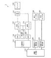
- FIG. 1 is a diagram showing a configuration example of a communication device 1 according to a first embodiment of the present technology.
- the communication device 1 moves the phase measurement block 110, the DAC 120, the transmission block 130, the frequency synthesizer 140, the RF switch 150, the antenna 160, the reception block 170, the ADC 180, the speed sensor unit 190, and the like.
- a speed calculation unit 200 and a distance generation unit 210 are provided.
- the communication device 1 can perform communication using, for example, a BLE (Bluetooth (registered trademark) Low Energy) method. With the BLE method, it is possible to cut the time required for operations that require a large amount of power, such as connection establishment and data communication, as much as possible. Therefore, the power consumption can be suppressed and the communication device 1 can be miniaturized.
- BLE Bluetooth (registered trademark) Low Energy
- the phase measurement block 110 is a block for measuring the phase characteristic of the frequency of the propagation channel with another communication device.
- the phase measurement block 110 includes a modulator 111 and a phase measurement unit 115.
- the modulator 111 performs signal modulation processing for communication.
- IQ modulation will be performed as an example of the modulation process.
- I-channel (In-phase: in-phase component) and Q-channel (Quadrature: orthogonal component) signals are used as baseband signals.
- the phase measuring unit 115 measures the phase characteristic of the frequency of the propagation channel with other communication devices.
- the phase measuring unit 115 measures the phase characteristic for each frequency based on the data of each signal of the I channel and the Q channel from the ADC 180.
- the phase measurement block 110 corresponds to the phase acquisition unit.
- the DAC 120 converts the digital signal from the modulator 111 into an analog signal.
- the analog signal converted by the DAC 120 is supplied to the transmission block 130.
- the transmission block 130 is a block that transmits a signal by wireless communication.
- the transmission block 130 includes a BPF 131 and a mixer 132.
- the BPF (Band-Pass Filter) 131 passes only signals in a specific frequency band. That is, the BPF 131 supplies only the signal of a specific frequency band to the mixer 132 in the analog signal from the DAC 120.
- the mixer 132 converts the signal supplied from the BPF 131 into the transmission frequency of wireless communication by mixing the local oscillation frequency supplied from the frequency synthesizer 140.
- the frequency synthesizer 140 supplies the frequency used for transmission and reception.
- the frequency synthesizer 140 includes a local oscillator (clock: CLK) 145 inside, and is used for converting a high frequency signal and a baseband signal for wireless communication.
- CLK local oscillator
- the RF switch 150 is a switch that switches a high frequency (RF: Radio Frequency) signal.
- the RF switch 150 connects the transmission block 130 to the antenna 160 at the time of transmission and connects the reception block 170 to the antenna 160 at the time of reception.
- the antenna 160 is an antenna for transmitting and receiving by wireless communication.
- the reception block 170 is a block that receives a signal by wireless communication.
- the reception block 170 has an LNA 171, a mixer 172, BPF 173 and 175, and VGA 174 and 176.
- the LNA (Low Noise Amplifier) 171 amplifies the RF signal received by the antenna 160.
- the mixer 172 converts the signals supplied from the LNA 171 into I-channel and Q-channel signals by mixing the local oscillation frequency supplied from the frequency synthesizer 140.
- the I-channel signal is supplied to BPF173, and the Q-channel signal is supplied to BPF175.
- VGA (Variable Gain Amplifier) 174 and 176 are analog variable gain amplifiers that adjust the gain of signals from BPF 173 and 175, respectively.
- the ADC (Analog-to-Digital Converter) 180 converts the I-channel and Q-channel signals from the reception block 170 from analog signals to digital signals.
- the speed sensor unit 190 is a sensor that measures speed.
- the speed sensor unit 190 can use a general speed sensor.
- the speed sensor unit 190 is, for example, an acceleration sensor.
- the speed can be obtained by time-integrating the output signal of the acceleration sensor.
- the acceleration sensor for example, a composite sensor including an acceleration sensor represented by an inertial measurement unit (IMU) can be used. Alternatively, a sensor that does not include an acceleration sensor may be used.
- the moving speed calculation unit 200 calculates the speed of the communication device 1 based on the output signal of the speed sensor unit 190.
- the distance generation unit 210 generates the distance to the object to be measured by using the phase information measured by the phase measurement block 110 and the movement speed information calculated by the movement speed calculation unit 200. The details of the distance generation unit 210 will be described later.
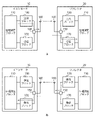
- FIG. 2 is a diagram showing an example of phase measurement of the communication system according to the first embodiment.
- a measurement signal is transmitted from one communication device (initiator 10) to the other communication device (reflector 20).
- the above-mentioned communication device can be used as either the initiator 10 or the reflector 20.
- the measurement signal is transmitted from the phase measurement block 110 through the transmission block 130 and from the antenna 160. Further, in the reflector 20, the measurement signal is received by the reception block 170 through the antenna 160.
- the measurement signal is returned from the reflector 20 to the initiator 10. That is, in the reflector 20, the measurement signal is transmitted from the phase measurement block 110 through the transmission block 130 and from the antenna 160. Further, in the initiator 10, the measurement signal is received by the reception block 170 through the antenna 160, and the phase characteristic between the two is measured in the phase measurement block 110. By performing reciprocating communication in this way, it is possible to measure the phase characteristics between communication devices.
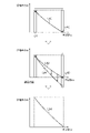
- FIG. 3 is a diagram showing measurement results of the phase measuring unit 115 with respect to frequencies of 80 channels of frequencies ⁇ 1 to ⁇ 80, for example.
- the vertical axis represents the phase difference ⁇ m measured by the phase measuring unit 115, and the horizontal axis represents the frequency.
- the frequency is 80 channels of ⁇ 1 to ⁇ 80 in the 2.4 GHz band.
- the above figure shows the measurement result of frequency ⁇ 1.
- the middle figure shows the measurement result of the frequency ⁇ 80.
- the figure below shows the measurement results of frequencies ⁇ 1 to ⁇ 80. As shown in FIG.
- phase difference ⁇ m changes according to the frequency.
- the example of 80 channels will be described, but the present invention is not limited to this. For example, distance measurement is possible if there are measurement results of two or more channels.
- the distance generation unit 210 calculates the group delay ⁇ from the slope of the phase difference ⁇ m when the speed is equal to or less than a predetermined value by the movement speed calculation unit 200, and generates the distance.
- the group delay ⁇ is obtained by differentiating the phase difference ⁇ m between the input waveform and the output waveform with the angular frequency ⁇ . Since the phase cannot be distinguished from the phase shifted by an integral multiple of 2 ⁇ , the group delay ⁇ is used as an index showing the characteristics of the filter circuit.
- phase difference ⁇ d may be referred to as a rotational phase.
- the distance D can be obtained by the equation (3).
- D (c / 2) ⁇ (d ⁇ m / d ⁇ ) (3)
- the phase measuring unit 115 measures the phase characteristic of the frequency of the propagation channel with other communication devices. In this way, if the speed is 0, for example, the distance generation unit 210 measures the phase difference ⁇ m, and if the slope (differential value based on the angular frequency ⁇ ) is known, the distance generation unit 210 generates distance information based on the phase characteristics. can do.
- the slope information of the phase difference ⁇ m with respect to the frequency is used, it is equivalent to calculating the distance from the relative difference information of the frequency. Therefore, the measurement accuracy is higher because it does not depend on the absolute value of the circuit delay of each block or the variation value due to the temperature characteristic.
- FIG. 4 is a diagram showing a problem when the communication device 1 is moving.
- the vertical axis represents the phase difference ⁇ m measured by the phase measuring unit 115, and the horizontal axis represents the frequency.
- the frequency is 80 channels of ⁇ 1 to ⁇ 80 in the 2.4 GHz band.
- the figure on the left shows the measurement result L40 of the phase difference ⁇ m with respect to the frequency ⁇ when the communication device 1 is stopped.
- the figure on the right shows the measurement result L42 of the phase difference ⁇ m with respect to the frequency ⁇ when the communication device 1 is moving.
- the distance measuring method of the phase difference ⁇ m measured by the phase measuring unit 115 the distance is measured based on the phase change when the frequency changes. If the position of the communication device 1 changes during the measurement, the measurement result is L42, which deviates from the true value of the measurement result L40.
- the moving speed of the communication device 1 is 10 km / h.
- the movement distance DV during frequency sweep is expressed by Eq. (4) by the movement speed V, the frequency sweep time Ts, and the wavelength ⁇ .
- V the average moving speed of the frequency sweep time Ts
- ⁇ the wavelength of the final channel.
- the corrected phase difference ⁇ m'in the final channel is expressed by Eq. (5).
- ⁇ m' ⁇ m-DV / ( ⁇ ⁇ 360) (5)
- the correction phase difference ⁇ m'of each channel can be calculated.
- Eq. (1) can be shown as Eq. (6), and Eq. (7) can be obtained by differentiating both sides of Eq. (6) with the angular frequency ⁇ .
- the moving distance DV is indicated by a plus
- the communication device 1 is approaching, it is indicated by a minus.
- ⁇ d' ⁇ m'+ 2 ⁇ n (6)
- the corrected distance D can be obtained by the equation (8).
- D (c / 2) ⁇ (d ⁇ m'/ d ⁇ ) (8)
- FIG. 5 is a diagram showing an example of speed correction when the communication device 1 is moving away from the object to be measured.
- the upper figure of FIG. 5 is a diagram showing, for example, the phase difference ⁇ m, which is the measurement result of the phase measuring unit 115 with respect to the frequencies of 80 channels of frequencies ⁇ 1 to ⁇ 80, on the line L50.
- the vertical axis represents the phase difference ⁇ m measured by the phase measuring unit 115
- the horizontal axis represents the frequency ⁇ .
- the frequency is 80 channels of ⁇ 1 to ⁇ 80 in the 2.4 GHz band.
- the frequency band is not limited to 80 channels of ⁇ 1 to ⁇ 80 in the 2.4 GHz band, and can be corrected if it is possible to measure two channels of an arbitrary frequency.
- the middle figure of FIG. 5 is a diagram schematically showing the speed correction according to the equation (5).
- the line L52 indicates a correction phase amount ⁇ m ′ in which the line L50 is corrected according to the equation (5).
- the length of the arrow schematically indicates the amount of correction for each channel.
- the length of the arrow of ⁇ 80 corresponds to DV / ( ⁇ ⁇ 360), which is the correction amount at ⁇ 80. That is, in FIG. 5, the communication device 1 is away from the object to be measured.
- the lower figure of FIG. 5 is a diagram showing a corrected phase amount ⁇ m'in which the phase difference of each channel is speed-corrected according to the equation (5) on the line L52.
- FIG. 6 is a diagram showing an example of speed correction when the communication device 1 is approaching the object to be measured.
- the upper figure of FIG. 6 is a diagram showing, for example, the phase difference ⁇ m, which is the measurement result of the phase measuring unit 115 with respect to the frequencies of 80 channels of frequencies ⁇ 1 to ⁇ 80, on the line L770.
- the vertical axis represents the phase difference ⁇ m measured by the phase measuring unit 115, and the horizontal axis represents the frequency.
- the frequency is 80 channels of ⁇ 1 to ⁇ 80 in the 2.4 GHz band.
- the middle figure of FIG. 6 is a diagram schematically showing the speed correction according to the equation (5).
- the line L54 indicates a correction phase amount ⁇ m ′ in which the line L50 is corrected according to the equation (5).
- the length of the arrow of ⁇ 80 corresponds to DV / ( ⁇ ⁇ 360). That is, in FIG. 6, the communication device 1 is approaching from the object to be measured.
- the lower figure of FIG. 6 is a diagram showing a corrected phase amount ⁇ m'corrected by speed according to the equation (5) on the line L54.
- FIG. 7A is a diagram showing a distance measurement result based on the moving speed when the communication device 1 is approaching the object to be measured.
- the horizontal axis shows the measurement time, and the vertical axis shows the distance measurement result.
- the line L58 shows the correct answer value, and the line L60 shows the distance measurement result when the speed is not corrected.
- the line L60 has an offset (phase rotation due to movement) with respect to the line L58.
- FIG. 7B is a diagram showing a distance measurement distance correction result based on the moving speed.
- the horizontal axis shows the measurement time, and the vertical axis shows the distance measurement result.
- the line L70 shows the correct answer value
- the line L72 shows the distance measurement result when the speed is not corrected
- the line L74 shows the correction result using the movement speed information.
- the influence of the offset of the distance measurement result (the amount of phase rotation due to the movement) is corrected.
- the line L60 of FIG. 7A can bring the value of the phase difference closer to the line L58 by performing the distance measuring distance correction using the moving speed information.
- the amount of rotation of the moving object may be acquired by another sensor (such as the IMU described above) and used for correcting the moving speed.
- other corrections for calculating the moving speed may be performed to improve the accuracy.
- FIG. 8 is a flowchart showing a processing example of the communication device 1 according to the present embodiment.
- the distance generation unit 210 acquires the information of the phase difference ⁇ m measured by the phase measurement unit 115 (step S100).
- the distance generation unit 210 acquires the speed information of the communication device 1 corresponding to each channel during frequency sweep from the movement speed calculation unit 200 (step S102).
- the distance generation unit 210 determines whether or not the speed of the communication device 1 is equal to or higher than a predetermined value by using the speed information of the communication device 1 during frequency sweep (step S104).
- the predetermined value is the speed determined based on the measurement error of the speed sensor unit 190.
- the predetermined value is the speed corresponding to the measurement error of the speed sensor unit 190.
- the distance generation unit 210 generates the distance information according to the equations (1) to (3), for example, without using the speed information. Calculate (step S106) and end the process.
- the distance information is calculated according to the equations (4) to (8), for example, using the speed information (step S108). End the process.
- the movement distance corresponding to each channel is calculated using the speed information of the communication device 1, and the phase difference corrected by using the phase difference corresponding to each movement distance. It was decided to generate ⁇ m'. As a result, it is possible to suppress a measurement error due to the movement of the communication device 1 during measurement. Therefore, the distance to the object to be measured can be measured with higher accuracy. Further, when the speed of the communication device 1 is equal to or less than a predetermined value, the communication device 1 generates the distance to the object to be measured without using the speed information of the communication device 1. As a result, the influence of the measurement error of the speed sensor unit 190 can be suppressed.
- the communication device 1 according to the second embodiment further includes a control unit 220 that controls synchronization of each channel of the measurement signal generated by the phase measurement block 110, the speed sensor unit 190, and the distance generation unit 210. 1 It is different from the communication device 1 according to the embodiment. Hereinafter, the differences from the communication device 1 according to the first embodiment will be described.
- FIG. 9 is a diagram showing a configuration example of the communication device 1 according to the second embodiment of the present technology. As shown in FIG. 9, it differs from the communication device 1 according to the first embodiment in that it further includes a control unit 220.
- the control unit 220 performs synchronous control of each channel of the measurement signal of the transmission block 130, the speed sensor unit 190, and the distance generation unit 210. This makes it possible to synchronize the movement speed information acquired by the speed sensor unit 190 with the phase information acquired by the phase measurement block 110. More specifically, the control unit 220 synchronizes the timing of the signal modulation processing corresponding to each channel by the modulator 111 of the phase measurement block 110 with the measurement timing of the speed sensor unit 190. As a result, the distance generation unit 210 can correct the phase difference represented by the equations (4) to (6) with higher accuracy by using the speed information V synchronized with the phase difference information ⁇ m. It will be possible.
- control unit 220 always operates one of the modulator 111 and the speed sensor unit 190 of the phase measurement block 110, and starts the operation of the other in accordance with the measurement start timing of the phase difference ⁇ m.
- the distance generation unit 210 can also perform a process of synchronizing the timing of the signal modulation processing corresponding to each channel with the corresponding speed information. Further, when the activation start timing of the speed sensor unit 190 is adjusted according to the timing of the signal modulation processing corresponding to each channel by the modulator 111, the power consumption of the speed sensor unit 190 can be suppressed.
- the communication device 1 according to the third embodiment is different from the communication device 1 according to the first embodiment in that it further includes a direction sensor unit 230 and a movement direction calculation unit 240.
- a direction sensor unit 230 and a movement direction calculation unit 240.
- FIG. 10 is a diagram showing a configuration example of the communication device 1 according to the third embodiment of the present technology. As shown in FIG. 10, it differs from the communication device 1 according to the first embodiment in that it further includes a direction sensor unit 230 and a movement direction calculation unit 240.
- the direction sensor unit 230 acquires information on the moving direction of the communication device 1 with respect to the object to be measured.
- a general direction sensor can be used for the direction sensor unit 230.
- a gyro sensor, an acceleration sensor, a geomagnetic sensor, or the like can be used as the direction sensor unit 230.
- the acceleration sensor for example, a composite sensor including an acceleration sensor represented by the above-mentioned inertial measurement unit (IMU) can be used.
- IMU inertial measurement unit
- a sensor that does not include an acceleration sensor may be used.
- the moving direction calculation unit 240 calculates the traveling direction of the communication device 1 based on the output signal of the direction sensor unit 230.
- the scalar value of speed is referred to as speed.
- the velocity is a vector value having information on the velocity and the traveling direction.
- the distance generation unit 210 moves the distance DV when the communication device 1 is away from the object to be measured in the above-mentioned correction formula (5) based on the direction calculated by the movement direction calculation unit 240. Is indicated by a plus, and when approaching, an operation indicated by a minus is performed. If the direction of the communication device 1 with respect to the object to be measured and the direction calculated by the moving direction calculation unit 240 are different from each other, the equations (1) to (8) may be corrected by a triangular calculation.
- FIG. 11 is a diagram showing an increase / decrease in the distance calculated by the distance generation unit 210 when the direction information is not used. That is, the case where the time derivative of the distance increases is indicated by a number larger than 1, and the case where the time derivative decreases is indicated by less than 1. 1 means stop. As shown in FIG. 11, even when the direction information is not used, it is possible to determine whether the communication device 1 is approaching or moving away from the object to be measured from the distance information calculated by the distance generation unit 210.
- the distance generation unit 210 can determine that the distance is moving away when the time derivative of the distance calculated without using the direction information increases, and that the distance is approaching when the time derivative decreases. be.
- the distance generation unit 210 indicates the moving distance DV as a plus when it is determined that the communication device 1 is moving away from the object to be measured, and shows a minus when it is determined that the communication device 1 is approaching. Perform the calculation again. As a result, it is possible to generate a distance in consideration of the direction even when the direction sensor unit 230 is not provided.
- FIG. 12 is a flowchart showing a processing example of the communication device 1 according to the third embodiment.
- the distance generation unit 210 receives the speed information of the communication device 1 during frequency sweep from the movement speed calculation unit 200 and the movement direction calculation unit.
- the direction information is acquired from 240 as speed information (step S202).
- the distance generation unit 210 determines whether or not the speed of the communication device 1 is equal to or higher than a predetermined value by using the speed information of the communication device 1 during frequency sweep (step S204).
- step S204 when the speed of the communication device 1 is less than a predetermined value (No in step S204), the distance generation unit 210 performs the process of step S106 (see FIG. 8) and ends the process.
- the distance information is calculated according to the equations (4) to (8), for example, using the speed information and the direction information (step). S208), the process is terminated.
- the communication device 1 has decided to generate information on the traveling direction with respect to the object to be measured for each measurement.
- the distance generation unit 210 can accurately calculate the correction calculation based on the equation (5) by using the generated information on the traveling direction. Therefore, the distance to the object to be measured can be calculated with higher accuracy.
- the present technology can have the following configurations. (1) A phase acquisition unit that acquires the phase characteristics of the frequency in the propagation channel with another communication device, and A distance generator that generates distance information based on the phase characteristics, A speed sensor unit that can be used to correct the phase characteristics and measures the moving speed of the transmitting side of the propagation channel, and A communication device.
- the communication device according to any one of (1) to (8), further including a direction sensor unit for measuring the moving direction of the transmission side of the propagation channel.
- phase acquisition unit measures the phase characteristics by transmission / reception to / from the other communication device.
- phase acquisition unit generates the phase characteristic based on a transmission / reception signal via the antenna.
- a communication system including first and second communication devices for transmitting and receiving measurement signals to and from each other.
- the first communication device includes a phase acquisition unit that acquires the phase characteristic of the frequency of the propagation channel when the measurement signal is transmitted / received to / from the second communication device.
- a distance generator that generates distance information based on the phase characteristics
- a speed sensor unit that can be used to correct the phase characteristics and measures the moving speed of the transmitting side of the propagation channel, and A communication system.
- a step of generating a phase characteristic of a frequency in a propagation channel with another communication device and The step of measuring the moving speed of the transmitting side of the propagation channel and A step of correcting the phase characteristic by the moving speed and generating distance information, A communication method that includes.
Landscapes
- Engineering & Computer Science (AREA)
- Radar, Positioning & Navigation (AREA)
- Remote Sensing (AREA)
- Computer Networks & Wireless Communication (AREA)
- Physics & Mathematics (AREA)
- General Physics & Mathematics (AREA)
- Radar Systems Or Details Thereof (AREA)
Priority Applications (4)
| Application Number | Priority Date | Filing Date | Title |
|---|---|---|---|
| KR1020237024582A KR20230159365A (ko) | 2021-01-18 | 2021-12-16 | 통신 장치, 통신 시스템 및 통신 방법 |
| JP2022575152A JPWO2022153773A1 (https=) | 2021-01-18 | 2021-12-16 | |
| US18/261,034 US20240085550A1 (en) | 2021-01-18 | 2021-12-16 | Communication apparatus, communication system, and communication method |
| CN202180088920.1A CN116724249A (zh) | 2021-01-18 | 2021-12-16 | 通信装置、通信系统和通信方法 |
Applications Claiming Priority (2)
| Application Number | Priority Date | Filing Date | Title |
|---|---|---|---|
| JP2021005526 | 2021-01-18 | ||
| JP2021-005526 | 2021-01-18 |
Publications (1)
| Publication Number | Publication Date |
|---|---|
| WO2022153773A1 true WO2022153773A1 (ja) | 2022-07-21 |
Family
ID=82447235
Family Applications (1)
| Application Number | Title | Priority Date | Filing Date |
|---|---|---|---|
| PCT/JP2021/046429 Ceased WO2022153773A1 (ja) | 2021-01-18 | 2021-12-16 | 通信装置、通信システム及び通信方法 |
Country Status (5)
| Country | Link |
|---|---|
| US (1) | US20240085550A1 (https=) |
| JP (1) | JPWO2022153773A1 (https=) |
| KR (1) | KR20230159365A (https=) |
| CN (1) | CN116724249A (https=) |
| WO (1) | WO2022153773A1 (https=) |
Cited By (2)
| Publication number | Priority date | Publication date | Assignee | Title |
|---|---|---|---|---|
| US20220166437A1 (en) * | 2020-03-19 | 2022-05-26 | Kabushiki Kaisha Toshiba | Phase correcting device, distance measuring device, phase fluctuation detecting device and phase correction method |
| JPWO2023248540A1 (https=) * | 2022-06-21 | 2023-12-28 |
Citations (6)
| Publication number | Priority date | Publication date | Assignee | Title |
|---|---|---|---|---|
| US20080143584A1 (en) * | 2006-12-18 | 2008-06-19 | Radiofy Llc, A California Limited Liability Company | Method and system for determining the distance between an RFID reader and an RFID tag using phase |
| JP2012103162A (ja) * | 2010-11-11 | 2012-05-31 | Alps Electric Co Ltd | 距離測定装置 |
| JP2018048821A (ja) * | 2016-09-20 | 2018-03-29 | 株式会社東海理化電機製作所 | 電波伝搬距離推定装置 |
| JP2020026970A (ja) * | 2018-08-09 | 2020-02-20 | パナソニックIpマネジメント株式会社 | 距離測定装置、距離測定システムおよび距離測定方法 |
| WO2020077222A1 (en) * | 2018-10-12 | 2020-04-16 | Denso International America, Inc. | Passive entry/passive start systems detecting range extender type relay station attacks |
| JP2020134169A (ja) * | 2019-02-13 | 2020-08-31 | 株式会社東海理化電機製作所 | 位置検出システム及び位置検出方法 |
Family Cites Families (11)
| Publication number | Priority date | Publication date | Assignee | Title |
|---|---|---|---|---|
| US7800541B2 (en) * | 2008-03-31 | 2010-09-21 | Golba Llc | Methods and systems for determining the location of an electronic device |
| JP5025675B2 (ja) | 2009-03-19 | 2012-09-12 | 三菱電機株式会社 | 移動体検知システム |
| EP3147685B1 (en) * | 2015-09-22 | 2020-01-01 | Veoneer Sweden AB | A vehicle synthetic aperture radar system |
| JP6829833B2 (ja) | 2017-02-01 | 2021-02-17 | 株式会社東海理化電機製作所 | 電波伝搬距離推定装置 |
| US11889459B2 (en) * | 2019-03-07 | 2024-01-30 | Koninklijke Kpn N.V. | Phase-based distance determination for wireless networks |
| EP3722831A1 (en) * | 2019-04-10 | 2020-10-14 | Stichting IMEC Nederland | Method of wireless ranging |
| EP3751303B1 (en) * | 2019-06-12 | 2022-11-02 | Stichting IMEC Nederland | System and method for distance and velocity estimation in phase-based ranging |
| US11609305B2 (en) * | 2019-12-27 | 2023-03-21 | Intel Corporation | Online radar phase calibration through static environment measurements |
| US11422250B2 (en) * | 2020-08-28 | 2022-08-23 | Nxp Usa, Inc. | Method and technique of power-efficient two-way phase based distance estimation using packet synchronized data capture |
| CN116762046A (zh) * | 2020-11-18 | 2023-09-15 | 交互数字Ce专利控股有限公司 | 用于获得环境的观测数据的方法和装置 |
| US11527117B2 (en) * | 2021-01-11 | 2022-12-13 | Ford Global Technologies, Llc | Interference avoiding distance measurement |
-
2021
- 2021-12-16 JP JP2022575152A patent/JPWO2022153773A1/ja not_active Abandoned
- 2021-12-16 WO PCT/JP2021/046429 patent/WO2022153773A1/ja not_active Ceased
- 2021-12-16 US US18/261,034 patent/US20240085550A1/en active Pending
- 2021-12-16 CN CN202180088920.1A patent/CN116724249A/zh not_active Withdrawn
- 2021-12-16 KR KR1020237024582A patent/KR20230159365A/ko active Pending
Patent Citations (6)
| Publication number | Priority date | Publication date | Assignee | Title |
|---|---|---|---|---|
| US20080143584A1 (en) * | 2006-12-18 | 2008-06-19 | Radiofy Llc, A California Limited Liability Company | Method and system for determining the distance between an RFID reader and an RFID tag using phase |
| JP2012103162A (ja) * | 2010-11-11 | 2012-05-31 | Alps Electric Co Ltd | 距離測定装置 |
| JP2018048821A (ja) * | 2016-09-20 | 2018-03-29 | 株式会社東海理化電機製作所 | 電波伝搬距離推定装置 |
| JP2020026970A (ja) * | 2018-08-09 | 2020-02-20 | パナソニックIpマネジメント株式会社 | 距離測定装置、距離測定システムおよび距離測定方法 |
| WO2020077222A1 (en) * | 2018-10-12 | 2020-04-16 | Denso International America, Inc. | Passive entry/passive start systems detecting range extender type relay station attacks |
| JP2020134169A (ja) * | 2019-02-13 | 2020-08-31 | 株式会社東海理化電機製作所 | 位置検出システム及び位置検出方法 |
Cited By (5)
| Publication number | Priority date | Publication date | Assignee | Title |
|---|---|---|---|---|
| US20220166437A1 (en) * | 2020-03-19 | 2022-05-26 | Kabushiki Kaisha Toshiba | Phase correcting device, distance measuring device, phase fluctuation detecting device and phase correction method |
| US11664807B2 (en) * | 2020-03-19 | 2023-05-30 | Kabushiki Kaisha Toshiba | Phase correcting device, distance measuring device, phase fluctuation detecting device and phase correction method |
| JPWO2023248540A1 (https=) * | 2022-06-21 | 2023-12-28 | ||
| WO2023248540A1 (ja) * | 2022-06-21 | 2023-12-28 | アルプスアルパイン株式会社 | 測距装置 |
| JP7730997B2 (ja) | 2022-06-21 | 2025-08-28 | アルプスアルパイン株式会社 | 測距装置 |
Also Published As
| Publication number | Publication date |
|---|---|
| KR20230159365A (ko) | 2023-11-21 |
| CN116724249A (zh) | 2023-09-08 |
| JPWO2022153773A1 (https=) | 2022-07-21 |
| US20240085550A1 (en) | 2024-03-14 |
Similar Documents
| Publication | Publication Date | Title |
|---|---|---|
| AU2017268026B2 (en) | Position estimation in a low earth orbit satellite communications system | |
| KR102407307B1 (ko) | 동적 위치 네트워크를 시간순으로 동기화하는 방법 및 장치 | |
| US8866672B2 (en) | Cooperative systems and methods for TDOA-based emitter location | |
| JP7698630B2 (ja) | 通信装置、通信システム及び通信方法 | |
| US20180206075A1 (en) | High-Resolution High-Dynamic Range Doppler-Effect Measurement Using Modulated Carrier Signals | |
| US20100156718A1 (en) | Method for calculating current position coordinate | |
| JP2021527223A (ja) | 部分調整されたレーダシステム | |
| KR20220098132A (ko) | 통신 장치 및 통신 방법 | |
| WO2022153773A1 (ja) | 通信装置、通信システム及び通信方法 | |
| JP2019039877A (ja) | 無線通信装置を用いた位置推定方法、位置推定装置及び携帯通信装置 | |
| KR20240008839A (ko) | 통신 장치, 거리측정 방법 | |
| US9395447B2 (en) | Orientation measurements for drift correction | |
| CN105578588A (zh) | 一种基站同步、定位方法和设备 | |
| CN115876153B (zh) | 一种编队航天器的高精度测角方法 | |
| US9651648B1 (en) | Phase difference of arrival geolocation | |
| CN119535343A (zh) | 一种复杂环境下多节点互定位方法及系统 | |
| US11777207B2 (en) | Virtual phased-array for coherent, distributed, and dynamic applications | |
| ES3021875T3 (en) | Methods and devices for geopositioning a first satellite telecommunication terminal, associated computer programs | |
| KR20030083225A (ko) | 위치 검출 방법과 그를 이용한 위치추적 시스템 및 그 방법 | |
| JP4073564B2 (ja) | Rtkシステム | |
| JP5422285B2 (ja) | 通信装置 | |
| RU2805163C1 (ru) | Навигационно-радиолокационная система радиозондирования атмосферы | |
| CN108776323B (zh) | 位置校正方法及装置 | |
| RU2818856C1 (ru) | Устройство измерения параметров радиосигналов пространственно-распределенной системы радиопередатчиков с использованием беспилотного летательного аппарата | |
| Talvitie et al. | Quaternion-Driven High-Precision 3D Position and Orientation Tracking for mmWave Radio Systems Using Delay-Doppler Measurements |
Legal Events
| Date | Code | Title | Description |
|---|---|---|---|
| 121 | Ep: the epo has been informed by wipo that ep was designated in this application |
Ref document number: 21919661 Country of ref document: EP Kind code of ref document: A1 |
|
| ENP | Entry into the national phase |
Ref document number: 2022575152 Country of ref document: JP Kind code of ref document: A |
|
| WWE | Wipo information: entry into national phase |
Ref document number: 202180088920.1 Country of ref document: CN |
|
| WWE | Wipo information: entry into national phase |
Ref document number: 18261034 Country of ref document: US |
|
| NENP | Non-entry into the national phase |
Ref country code: DE |
|
| 122 | Ep: pct application non-entry in european phase |
Ref document number: 21919661 Country of ref document: EP Kind code of ref document: A1 |
|
| WWW | Wipo information: withdrawn in national office |
Ref document number: 1020237024582 Country of ref document: KR |