EP3722831A1 - Method of wireless ranging - Google Patents
Method of wireless ranging Download PDFInfo
- Publication number
- EP3722831A1 EP3722831A1 EP19168443.0A EP19168443A EP3722831A1 EP 3722831 A1 EP3722831 A1 EP 3722831A1 EP 19168443 A EP19168443 A EP 19168443A EP 3722831 A1 EP3722831 A1 EP 3722831A1
- Authority
- EP
- European Patent Office
- Prior art keywords
- node
- initiator
- responder
- clock reference
- nominal
- Prior art date
- Legal status (The legal status is an assumption and is not a legal conclusion. Google has not performed a legal analysis and makes no representation as to the accuracy of the status listed.)
- Pending
Links
Images


Classifications
-
- G—PHYSICS
- G01—MEASURING; TESTING
- G01S—RADIO DIRECTION-FINDING; RADIO NAVIGATION; DETERMINING DISTANCE OR VELOCITY BY USE OF RADIO WAVES; LOCATING OR PRESENCE-DETECTING BY USE OF THE REFLECTION OR RERADIATION OF RADIO WAVES; ANALOGOUS ARRANGEMENTS USING OTHER WAVES
- G01S5/00—Position-fixing by co-ordinating two or more direction or position line determinations; Position-fixing by co-ordinating two or more distance determinations
- G01S5/02—Position-fixing by co-ordinating two or more direction or position line determinations; Position-fixing by co-ordinating two or more distance determinations using radio waves
- G01S5/0246—Position-fixing by co-ordinating two or more direction or position line determinations; Position-fixing by co-ordinating two or more distance determinations using radio waves involving frequency difference of arrival or Doppler measurements
-
- G—PHYSICS
- G01—MEASURING; TESTING
- G01S—RADIO DIRECTION-FINDING; RADIO NAVIGATION; DETERMINING DISTANCE OR VELOCITY BY USE OF RADIO WAVES; LOCATING OR PRESENCE-DETECTING BY USE OF THE REFLECTION OR RERADIATION OF RADIO WAVES; ANALOGOUS ARRANGEMENTS USING OTHER WAVES
- G01S13/00—Systems using the reflection or reradiation of radio waves, e.g. radar systems; Analogous systems using reflection or reradiation of waves whose nature or wavelength is irrelevant or unspecified
- G01S13/74—Systems using reradiation of radio waves, e.g. secondary radar systems; Analogous systems
- G01S13/82—Systems using reradiation of radio waves, e.g. secondary radar systems; Analogous systems wherein continuous-type signals are transmitted
- G01S13/84—Systems using reradiation of radio waves, e.g. secondary radar systems; Analogous systems wherein continuous-type signals are transmitted for distance determination by phase measurement
-
- G—PHYSICS
- G01—MEASURING; TESTING
- G01S—RADIO DIRECTION-FINDING; RADIO NAVIGATION; DETERMINING DISTANCE OR VELOCITY BY USE OF RADIO WAVES; LOCATING OR PRESENCE-DETECTING BY USE OF THE REFLECTION OR RERADIATION OF RADIO WAVES; ANALOGOUS ARRANGEMENTS USING OTHER WAVES
- G01S5/00—Position-fixing by co-ordinating two or more direction or position line determinations; Position-fixing by co-ordinating two or more distance determinations
- G01S5/02—Position-fixing by co-ordinating two or more direction or position line determinations; Position-fixing by co-ordinating two or more distance determinations using radio waves
- G01S5/0205—Details
- G01S5/0221—Receivers
- G01S5/02213—Receivers arranged in a network for determining the position of a transmitter
- G01S5/02216—Timing or synchronisation of the receivers
-
- G—PHYSICS
- G01—MEASURING; TESTING
- G01S—RADIO DIRECTION-FINDING; RADIO NAVIGATION; DETERMINING DISTANCE OR VELOCITY BY USE OF RADIO WAVES; LOCATING OR PRESENCE-DETECTING BY USE OF THE REFLECTION OR RERADIATION OF RADIO WAVES; ANALOGOUS ARRANGEMENTS USING OTHER WAVES
- G01S5/00—Position-fixing by co-ordinating two or more direction or position line determinations; Position-fixing by co-ordinating two or more distance determinations
- G01S5/02—Position-fixing by co-ordinating two or more direction or position line determinations; Position-fixing by co-ordinating two or more distance determinations using radio waves
- G01S5/0257—Hybrid positioning
- G01S5/0268—Hybrid positioning by deriving positions from different combinations of signals or of estimated positions in a single positioning system
- G01S5/02685—Hybrid positioning by deriving positions from different combinations of signals or of estimated positions in a single positioning system involving dead reckoning based on radio wave measurements
-
- G—PHYSICS
- G01—MEASURING; TESTING
- G01S—RADIO DIRECTION-FINDING; RADIO NAVIGATION; DETERMINING DISTANCE OR VELOCITY BY USE OF RADIO WAVES; LOCATING OR PRESENCE-DETECTING BY USE OF THE REFLECTION OR RERADIATION OF RADIO WAVES; ANALOGOUS ARRANGEMENTS USING OTHER WAVES
- G01S5/00—Position-fixing by co-ordinating two or more direction or position line determinations; Position-fixing by co-ordinating two or more distance determinations
- G01S5/02—Position-fixing by co-ordinating two or more direction or position line determinations; Position-fixing by co-ordinating two or more distance determinations using radio waves
- G01S5/0284—Relative positioning
Definitions
- the present inventive concept relates to methods and devices for wireless ranging.
- Ranging involves determining the distances between wireless nodes.
- Multi-carrier Phase Difference Ranging is a known method used to estimate the distance between two wireless nodes based on phase difference of two or more carrier signals. It may be implemented in narrowband systems like Bluetooth, Bluetooth Low Energy (BLE), IEEE 802.15.4 (e.g., Zigbee), and others. An example implementation of such a method is disclosed in W. Kluge and D. Eggert, "Ranging with IEEE 802.15.4 narrowband PHY", IEEE P802.15 Working Group for Wireless Personal Area Networks (WPANs), September 2009, https://mentor.ieee.org/802.15/dcn/1915-09-0613-01-004franging-with-ieee-802-15-4-narrow-band-phy.ppt .
- An objective of the present inventive concept is to provide methods and devices for wireless ranging with improved accuracy.
- a method of wireless ranging between an initiator node and a responder node comprising, for each nominal frequency in a plurality of nominal frequencies, performing a measurement procedure resulting in a two-way phase measurement between the initiator node the responder node, the measurement procedure comprising the initiator node transmitting an initiator carrier signal, the frequency of the initiator carrier signal being derived from an initiator node clock reference; the responder node performing a phase measurement of the initiator carrier signal relative to a responder node clock reference; the responder node transmitting a responder carrier signal, the frequency of the initiator carrier signal being derived from the responder clock reference; and the initiator node performing a phase measurement of the responder carrier signal relative to the initiator node clock reference, the method further comprising calculating a distance between the initiator node and the responder node using as input the two-way phase measurements for the plurality of nominal frequencies; and a clock reference offset correction of the initiator node
- carrier signal should be understood a continuous-wave sinusoidal oscillation with a single frequency-component (neglecting harmonics and other imperfections). Such a signal may typically originate directly from the local oscillator (LO) of the transmitting node. However, as an example, it can also be obtained by applying a constant modulation, such as a frequency shift keying (FSK) modulation with a constant input (all 1s or 0s).
- LO local oscillator
- FSK frequency shift keying
- initiator node and "responder node” should be understood as labels for the functions the nodes perform with respect to the present disclosure, rather than as designating permanent functions for the respective nodes in the wireless network.
- a node at one point acting as an "initiator node” according to the present disclosure may at some other point act as a "responder node”, or vice versa.
- initiator node should be understood a node that performs the first carrier transmission during the measurement procedure, regardless of whether a decision to start the measurement procedure or the ranging originated in that node or elsewhere.
- clock reference should be understood any device providing a reference for the frequency of the transmitted carrier signal.
- the clock reference also provides a reference of the timing of such transmissions and of the phase measurements.
- the clock reference is a crystal reference.
- Performing a phase measurement relative to a clock reference should be understood to include, but not be limited to, performing the phase measurement relative to a reference signal which in turn, either indirectly or directly, has been derived from the clock reference, for example in generating internal frequencies used in downmixing in conjunction with the phase measurement.
- clock reference offset correction should be understood a correction to the calculated distance for effects of the clock reference at the initiator node and at the responder node deviating from their nominal values.
- this may for example be applied as a separate correction to a calculated distance, for example as a subtractive correction, or as a pre-distortion to the two-way phase measurements before calculating a distance.
- the phase measurements may for example be performed by collecting real (I) and imaginary (Q) samples from the received carrier signal.
- the clock reference offset correction may be measured and/or derived in conjunction with the measurement procedure, either before or after, for example through a carrier frequency offset, CFO, measurement. Alternatively, it may be known beforehand, for example from an earlier ranging procedure involving one or more of the initiator node and the responder node and for example stored in a database or transient or non-transient storage medium.
- a clock reference offset correction as input to the distance calculation for correction of effects of clock reference offsets on the calculated distance allows for the use of regular algorithms for distance calculation based on two-way phase measurements (MCPD) without requiring any extra phase measurements. Further, it allows accurate distance determination without the need for complicated calibrations, such as crystal tuning, or the use of more expensive and/or power-consuming clock references. Thus, cost and energy are saved. In particular, it allows accurate ranging using devices controlled by less accurate low-cost crystals, such as low-cost narrowband radios developed for e.g. Bluetooth Low Energy (BLE) and IEEE 802.15.4 (e.g., Zigbee). Such standards have been developed with low-cost in mind.
- BLE Bluetooth Low Energy
- IEEE 802.15.4 e.g., Zigbee
- the standards allow for the crystal offset, expressed in part-per-million (ppm), to deviate from -20 ppm to +20 ppm (IEEE 802.15.4) or even from -40 ppm to +40 ppm (BLE), reducing the overall Bill-of-Materials (BoM).
- MCPD ranging is especially attractive since it allows for accurate ranging while it can be used realized using commercially-of-the-shelf radios.
- the present inventive concept relies at least in part on the realization that crystal offsets of the initiator and reflector represent an additional significant bias during MCPD ranging with such devices, where the error can be as much as -2 to +2 meters or more depending on the timing.
- the present inventive concept allows for a simple method with low computational load.
- the clock reference offset correction is based on a relative clock reference offset difference ⁇ r - ⁇ i between a relative clock reference offset ⁇ i of the initiator node clock reference and a relative clock offset ⁇ r of the responder node clock reference.
- the device computing the distance typically the initiator node
- the only experimental parameter is the relative clock reference offset difference.
- the correction can be expressed in terms of only this one experimental parameter, leading to low complexity and therefore low cost, while retaining high accuracy.
- ⁇ r - ⁇ i the relative clock reference offset difference ⁇ r - ⁇ i , which can be regarded as the offset of the responder node clock reference with respect to the initiator clock reference.
- ⁇ r and ⁇ i may be expressed with respect to an absolute, perfect, reference.
- ⁇ r and ⁇ i may be expressed relative to the clock reference of one of the initiator node or the responder node, so that, for example, only a measurement of the offset of the reference node clock offset relative to the initiator node clock offset is required.
- the method further comprises one of the initiator node or the responder node performing a carrier frequency offset, CFO, measurement on a carrier signal transmitted by the other of the initiator node and the responder node; and deriving the relative clock reference offset difference from the carrier frequency offset.
- CFO carrier frequency offset
- the method further comprises one of the initiator node or the responder node performing a time offset difference, TOD, measurement on a message transmitted by the other of the initiator node and the responder node; and deriving the clock reference offset difference from the time offset difference.
- TOD time offset difference
- the calculating of the distance comprises calculating a preliminary distance between the initiator node and the responder node based on the plurality of nominal frequencies; and calculating a corrected distance between the initiator node and the responder node based on the nominal distance and the clock reference offset correction.
- the calculating of the distance comprises calculating a pre-distortion for the two-way phase measurements based on the clock reference offset correction; forming a pre-distorted set of two-way phase measurements by applying the pre-distortion to the two-way phase measurements; calculating the distance between the initiator node and the responder node based on the pre-distorted set of two-way phase measurements.
- This approach is also of advantage when the timing of the phase measurement may differ frequency by frequency, for example when performing ranging between three or more of nodes (group ranging), wherein, in the case of large-scale or dense deployments when the gap between the phase measurement at the initiator node and the phase measurement at the responder node will increase and/or vary.
- the initiator node clock reference and the responder node clock reference each is controlled by a crystal. This allows for a cheap construction whose drawbacks of lower clock reference accuracy may be mitigated well by the present inventive concept.
- a respective same clock reference controls both a clock timing the phase measurements and a local oscillator, LO.
- the initiator node and the responder node are Bluetooth Low Energy, BLE, devices. This is a technology with high requirements for low-power, low-cost devices for which the present inventive concept is particularly suitable.
- the initiator node and the responder node are IEEE 802.15.4, devices, such as Zigbee devices. This, too, is a technology with high requirements for low-power, low-cost devices for which the present inventive concept is particularly suitable.
- a method of wireless ranging between an initiator node and a responder node comprising gathering results from two-way phase measurements between an initiator node and a responder node for each nominal frequency in a plurality of nominal frequencies, calculating a distance between the initiator node and the responder node using as input the results from the two-way phase measurements; and a clock reference offset correction of the initiator node and of the responder node.
- a wireless ranging device configured to gather results from two-way phase measurements between an initiator node and a responder node for each nominal frequency in a plurality of nominal frequencies, calculate a distance between the initiator node and the responder node using as input the results from the two-way phase measurements; and a clock reference offset correction of the initiator node and of the responder node.
- the wireless ranging device is the initiator node.
- Fig. 1A shows schematically a wireless network 100.
- the wireless network 100 comprises for the purposes of the present disclosure an initiator node "I" 102 and a responder node “R" 104, separated by a distance d 106, which is to be determined by wireless ranging involving transmissions indicated by arrows.
- Fig. 1B shows a block diagram of a wireless network node, which may be the initiator node 102 or the responder node 104.
- the wireless network node may for example be a Bluetooth low-energy (BLE) device or a IEEE 802.15.4, device, such as a Zigbee device.
- BLE Bluetooth low-energy
- IEEE 802.15.4 IEEE 802.15.4
- a processor 105 which may be a microcontroller or CPU, controls the node 102, 104 by executing software 108.
- the processor 105 controls a radio front end (FE) 103 comprising an analog-to-digital converter (ADC) 110 and a phased-lock loop (PLL) 112 for generating a local oscillator signal (LO) used for transmitting a carrier signal or as a reference when performing a phase measurement when receiving a carrier signal.
- the radio front end 103 is connected to an antenna 114 for receiving or transmitting signals.
- a clock reference 116 here in the form of a crystal, provides a reference for both the processor 105 and the radio front end 103, i.e., the same crystal to derive the RF frequencies and generate the baseband clock driving the digital circuitry.
- any relative offset ⁇ in the frequency of the clock reference 116 will affect both the timing of transmissions and measurements, as controlled by the processor 105, and of the frequencies of transmitted carrier signals and of the reference used for phase measurements, both as generated by the LO controlled by the PLL 112, in turn controlled by the clock reference 116.
- Fig. 2 is a flowchart of a method example 200 of wireless ranging which may be implemented in the wireless network 100 (cf. Fig. 1 ).
- a frequency index i may be set to zero.
- the initiator node 102 may transmit a ranging request and the responder node may receive the ranging request and reply by transmitting a ranging acknowledgement. Further, a time synchronization may be performed between the clock of the initiator node 102 and the clock of the responder node 104.
- a measurement procedure 204-210 is performed, resulting in a two-way phase measurement between the initiator node 102 and the responder node 104, as will be detailed in the following.
- a two-way phase measurement i . e ., a measurement of the round-trip phase advance between a first node and a second node, such as the initiator node 102 and the responder node 104, may be performed based on a combination of a phase measurement performed at the second node with the first node transmitting and a phase measurement at the first node with the second node transmitting.
- phase measurement at the second node made with respect to the second node's LO which is also used for generating the carrier signal transmitted by the second node
- phase measurement done at the first node made with respect to the first node's LO which is used for generating the carrier signal transmitted by the first node
- the initiator node 102 transmits on frequency f i an initiator carrier signal, which received by the responder node 104.
- the responder node 104 performs a phase measurement of the initiator carrier signal.
- the responder node measures the phase of the initiator carrier signal with respect to the local oscillator (LO) of the responder node.
- LO local oscillator
- the responder node 104 transmits on frequency f i a responder carrier signal, which is received by the initiator node 102.
- the initiator node 102 performs a phase measurement of the responder carrier signal.
- the initiator node 102 and the responder node 104 may switch to the next frequency f i+ 1 and repeat the measurement procedure 204, 206.
- the measurement procedure is repeated several times at different frequencies.
- the responder node 104 may transmit its phase measurement results for each frequency f i . This transmission is received by the initiator node 102.
- a wireless ranging device in the form of a calculating node, which may be the initiator node 102, may calculate the distance d between the initiator node 102 and the responder node 104 based on the gathered measurement results, which involve the two-way phase for the plurality of frequencies f i .
- the calculating node may be separate and distinct from the initiator node 102. Used as input to the calculation are the phase measurement results, i.e., the two-way phase measurements for the plurality of nominal frequencies and a clock reference offset correction of the initiator node and of the responder node, as will be detailed further below.
- Fig. 3 is a timing diagram of transmissions by the responder node "R” 104 and the initiator node “I” 102 during the method example 200 (cf. Fig. 2 ). Transmissions by each respective node are marked “TX” and reception by "RX”.
- the nominal frequency of transmission starts at a frequency f 0 increases linearly with a frequency step ⁇ f , ending at a frequency fKf-1.
- At 212 is the transmission by the responder node 104 of the measurement results, received by the initiator node 102.
- Fig. 4A is a detailed timing diagram of transmissions with nominal frequencies and phase measurement times, showing a sequence of transmissions and phase measurements, wherein transmissions by the initiator node 102 are shown with dashed lines and transmissions by the responder node 104 are shown with solid lines. Similarly, the timings of phase measurements performed by the initiator node 102 are indicated with dashed arrows and the timing of measurements performed by the responder node 104 are indicated by solid arrows.
- the phase measurement 206 by the initiator node 102 of the carrier signal transmitted by the responder node 104 is separated from the phase measurement 204 by the responder node 104 of the carrier signal transmitted by the initiator node 102 by a time interval T 0 .
- the respective phase measurements 206 by the initiator node 102 of the carrier signals transmitted by the responder node 104 and the respective phase measurements 204 by the responder node 104 of the carrier signals transmitted by the responder node 104 are separated by a time interval T f .
- Fig. 4B is a detailed timing diagram of transmissions with example actual frequencies and phase measurement times. It illustrates, in an exaggerated manner, how, due to a relative clock reference offset ⁇ r of the responder node 104 clock reference 116 and a relative clock reference offset ⁇ i of the initiator node clock reference 116, the actual frequencies of the carrier signals transmitted by the initiator node 102 and the responder node 104 and the time intervals T 0 and T f deviate from their nominal values, as can be seen by the solid lines - the vertical position of which corresponding to frequencies transmitted by the initiator node 102 - not perfectly lining up with the dashed lines - corresponding to frequencies transmitted by the responder node 104 - and by the timing of the phase measurements - represented by the vertical arrows - not perfectly lining up with the nominal time intervals T 0 and T f - as represented by brackets - and also moving in relation to successive transmissions.
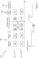
- Fig. 5A is a block diagram illustrating calculating, at 214 (cf. Figs 2 and 3 ), and possibly implemented in the software 108 of the initiator node 102, the distance d between the initiator node 102 and the responder node 104 according to a first approach, wherein, based on the two-way phase measurements, represented by a vector ⁇ 2W , a preliminary distance d prel is calculated by a ranging engine 602 using methods known per se. Subtracted from that preliminary distance d prel is a clock reference offset correction e r calculated by a bias calculator 604, having as input the relative clock reference offset difference ⁇ r - ⁇ i and a timing and frequency plan of the measurement procedure.
- T 0 is a nominal time difference between, for a given nominal frequency of the plurality of nominal frequencies, the phase measurement at the responder node and the phase measurement at the initiator node (cf. Fig 4A ), ⁇ r is a relative clock reference offset of the responder node clock reference, ⁇ i is a relative clock reference offset of the initiator node clock reference, f c is a nominal starting frequency of the plurality of nominal frequencies, ⁇ f is the nominal frequency step in the plurality of nominal frequencies (cf. Fig 4A ), K f is the number of frequencies in the plurality of nominal frequencies, F is an optional pre-programmed nominal frequency offset, and c 0 is a signal propagation speed.
- clock reference offset correction e r is based on the relative clock reference offset difference ⁇ r - ⁇ i between the relative clock reference offset ⁇ i of the initiator node clock reference and the relative clock offset ⁇ r of the responder node clock reference.
- the calculating of the distance comprises calculating a preliminary distance between the initiator node and the responder node based on the plurality of nominal frequencies; and calculating a corrected distance between the initiator node and the responder node based on the nominal distance and the clock reference offset correction.
- Fig. 5B is a block diagram illustrating calculating, at 214 (cf. Figs 2 and 3 ), and possibly implemented in the software 108 of the initiator node 102, the distance d between the initiator node 102 and the responder node 104 according to a second approach, wherein, pre-distortions represented by a vector ⁇ err is calculated at 606, having as input the relative clock reference offset difference ⁇ r - ⁇ i and a timing and frequency plan of the measurement procedure.
- the pre-distortions ⁇ err are subtracted from the two-way phase measurements ⁇ 2W and the distance d is calculated by a ranging engine 602 using methods known per se.
- the calculating of the distance comprises calculating a pre-distortion for the two-way phase measurements based on the clock reference offset correction; forming a pre-distorted set of two-way phase measurements by applying the pre-distortion to the two-way phase measurements; calculating the distance between the initiator node and the responder node based on the pre-distorted set of two-way phase measurements.
- Fig. 5C is a block diagram illustrating calculating, at 214 (cf. Figs 2 and 3 ), and possibly implemented in the software 108 of the initiator node 102, the distance d between the initiator node 102 and the responder node 104 according to a third approach, wherein in addition to the second approach, the two-way phase measurements ⁇ 2W , as modified by the pre-distortions ⁇ err , are subjected to a frequency reordering 608, having as input the frequency plan, before computation by the ranging engine 602. This allows for more flexibility in the frequency plan and/or time plan, e.g., when using frequency hopping as used in most narrowband radio standards like BLE and 802.15.4 .
- T o is here treated as a constant, however, the concept is easily generalized for other cases, such as group ranging.
- f k i and f k r are the actual frequencies generated by respectively the initiator node 102 and the responder node 104
- T k i , T k r represent the actual time at which the phase is measured at the initiator node 102 and the responder node 104, respectively.
- Other symbols are defined as above.
- the distance d can then be estimated by computing the phase-difference of the two-way phase measurements for consecutive frequencies.
- the actual frequencies and time-offset will scale in the presence of clock reference offsets.
- the variable F which denotes any programmed frequency to model a software-controlled frequency offset.
- ⁇ o tends to be much larger than ⁇ f .
- F 0 kHz and a crystal-offset of at most +-20 ppm
- ⁇ o is at least a factor 20 larger than ⁇ f .
- the relative clock reference offset difference ⁇ r - ⁇ i may be obtained by one of the initiator node 102 or the responder node 104 performing a carrier frequency offset, CFO, measurement on a carrier signal transmitted by the other of the initiator node 102 and the responder node 104 using methods known per se. Thereby, for example, a dedicated carrier signal may be sent, of which both the initiator and reflector know the targeted frequency ( F t ). Assuming the initiator node 102 sends the dedicated carrier signal, the responder node 104 can measure the so-called carrier frequency offset (CFO).
- This designated carrier signal for CFO measurement can be appended placed at different places in measurement procedure 200 (conf. Figs 2 , 4 ). It could be derived from the ranging request packet or the ranging request acknowledgement, which are exchanged at 202 between initiator and reflector before the phase-measurements 204, 206 to exchange upcoming ranging parameters. Alternatively, a dedicated carrier signal could be placed between the ranging acknowledgement and the first carrier signal exchange of the measurement procedure 200. It could even be placed in the middle or the end of the measurement procedure 200.
- the CFO can be measured by either the initiator node 102 and/or the responder node 104.
- the relative clock reference offset difference can be communicated to the wireless node, where the distance estimate is computed 214, typically the initiator node 102.
- the relative clock reference offset difference ⁇ r - ⁇ i may be obtained by one of the initiator node 102 or the responder node 104 performing two or more time measurements on specific events within a single message or multiple messages transmitted by the other of the initiator node 102 and the responder node 104, e.g., time of arrival of the synch frame delimiters or symbol timing, where the time offset difference(s), TOD, between these time measurements compared to the expected time offset difference(s) allows for an estimation of the relative reference offset difference.
Abstract
Description
- The present inventive concept relates to methods and devices for wireless ranging.
- Ranging involves determining the distances between wireless nodes.
- Multi-carrier Phase Difference Ranging (MCPD) is a known method used to estimate the distance between two wireless nodes based on phase difference of two or more carrier signals. It may be implemented in narrowband systems like Bluetooth, Bluetooth Low Energy (BLE), IEEE 802.15.4 (e.g., Zigbee), and others. An example implementation of such a method is disclosed in W. Kluge and D. Eggert, "Ranging with IEEE 802.15.4 narrowband PHY", IEEE P802.15 Working Group for Wireless Personal Area Networks (WPANs), September 2009, https://mentor.ieee.org/802.15/dcn/09/15-09-0613-01-004franging-with-ieee-802-15-4-narrow-band-phy.ppt .
- An objective of the present inventive concept is to provide methods and devices for wireless ranging with improved accuracy.
- According to a first aspect of the present inventive concept, there is provided a method of wireless ranging between an initiator node and a responder node, comprising, for each nominal frequency in a plurality of nominal frequencies, performing a measurement procedure resulting in a two-way phase measurement between the initiator node the responder node, the measurement procedure comprising the initiator node transmitting an initiator carrier signal, the frequency of the initiator carrier signal being derived from an initiator node clock reference; the responder node performing a phase measurement of the initiator carrier signal relative to a responder node clock reference; the responder node transmitting a responder carrier signal, the frequency of the initiator carrier signal being derived from the responder clock reference; and the initiator node performing a phase measurement of the responder carrier signal relative to the initiator node clock reference, the method further comprising calculating a distance between the initiator node and the responder node using as input the two-way phase measurements for the plurality of nominal frequencies; and a clock reference offset correction of the initiator node and of the responder node.
- With "carrier signal" should be understood a continuous-wave sinusoidal oscillation with a single frequency-component (neglecting harmonics and other imperfections). Such a signal may typically originate directly from the local oscillator (LO) of the transmitting node. However, as an example, it can also be obtained by applying a constant modulation, such as a frequency shift keying (FSK) modulation with a constant input (all 1s or 0s).
- The terms "initiator node" and "responder node" should be understood as labels for the functions the nodes perform with respect to the present disclosure, rather than as designating permanent functions for the respective nodes in the wireless network. For example, a node at one point acting as an "initiator node" according to the present disclosure may at some other point act as a "responder node", or vice versa. Further, with "initiator node" should be understood a node that performs the first carrier transmission during the measurement procedure, regardless of whether a decision to start the measurement procedure or the ranging originated in that node or elsewhere.
- With clock reference should be understood any device providing a reference for the frequency of the transmitted carrier signal.
- Typically, the clock reference also provides a reference of the timing of such transmissions and of the phase measurements.
- Typically, but not necessarily, the clock reference is a crystal reference.
- Performing a phase measurement relative to a clock reference should be understood to include, but not be limited to, performing the phase measurement relative to a reference signal which in turn, either indirectly or directly, has been derived from the clock reference, for example in generating internal frequencies used in downmixing in conjunction with the phase measurement.
- With clock reference offset correction should be understood a correction to the calculated distance for effects of the clock reference at the initiator node and at the responder node deviating from their nominal values. Mathematically, this may for example be applied as a separate correction to a calculated distance, for example as a subtractive correction, or as a pre-distortion to the two-way phase measurements before calculating a distance.
- The phase measurements may for example be performed by collecting real (I) and imaginary (Q) samples from the received carrier signal.
- The clock reference offset correction may be measured and/or derived in conjunction with the measurement procedure, either before or after, for example through a carrier frequency offset, CFO, measurement. Alternatively, it may be known beforehand, for example from an earlier ranging procedure involving one or more of the initiator node and the responder node and for example stored in a database or transient or non-transient storage medium.
- Using a clock reference offset correction as input to the distance calculation for correction of effects of clock reference offsets on the calculated distance allows for the use of regular algorithms for distance calculation based on two-way phase measurements (MCPD) without requiring any extra phase measurements. Further, it allows accurate distance determination without the need for complicated calibrations, such as crystal tuning, or the use of more expensive and/or power-consuming clock references. Thus, cost and energy are saved. In particular, it allows accurate ranging using devices controlled by less accurate low-cost crystals, such as low-cost narrowband radios developed for e.g. Bluetooth Low Energy (BLE) and IEEE 802.15.4 (e.g., Zigbee). Such standards have been developed with low-cost in mind. As a result, the standards allow for the crystal offset, expressed in part-per-million (ppm), to deviate from -20 ppm to +20 ppm (IEEE 802.15.4) or even from -40 ppm to +40 ppm (BLE), reducing the overall Bill-of-Materials (BoM). In such standards, MCPD ranging is especially attractive since it allows for accurate ranging while it can be used realized using commercially-of-the-shelf radios.
- The present inventive concept relies at least in part on the realization that crystal offsets of the initiator and reflector represent an additional significant bias during MCPD ranging with such devices, where the error can be as much as -2 to +2 meters or more depending on the timing.
- With the present inventive concept, the cost advantage mentioned above can be retained, while the problem of less accurate ranging due to the resulting crystal offset is mitigated.
- Compared to methods depending on crystal tuning, the need for tunable crystals and for network-wide tuning or tuning redone for each possible initiator-responder pair is avoided.
- Further, the present inventive concept allows for a simple method with low computational load.
- According to an embodiment, the clock reference offset correction is based on a relative clock reference offset difference ηr - ηi between a relative clock reference offset ηi of the initiator node clock reference and a relative clock offset ηr of the responder node clock reference.
- The relative clock reference offset η should be understood as the offset the rate of the clock reference from a reference value, expressed as a ratio to a reference value subtracted by 1. For example, if a crystal frequency is offset from the reference value by 1 ppm, η = 10-6.
- In the common case of the same clock reference controlling both the transmitted carrier frequencies and the timing of the phase measurements performed in each of the initiator node and the responder node, it has been found that the appropriate correction to the calculated distance, to a good approximation, can be expressed as a function only of only nominal (i.e., ideal, unaffected by clock reference offset) values for the carrier frequencies, of nominal values for the timing of the phase measurements and of the relative clock reference offset. During the ranging procedure the former two are known in advance, or the initiator node and the reflector only need to agree on the nominal (targeted) frequencies used as well as the nominal (targeted) timing of events. Hence, if the device computing the distance (typically the initiator node) knows all these parameters it can predict the bias and compensate for it. The only experimental parameter is the relative clock reference offset difference. Thus, the correction can be expressed in terms of only this one experimental parameter, leading to low complexity and therefore low cost, while retaining high accuracy.
- Due to the small values of η, to a good approximation, several definitions of the reference value are equivalent when calculating the relative clock reference offset difference ηr - ηi , which can be regarded as the offset of the responder node clock reference with respect to the initiator clock reference. For example, both ηr and ηi may be expressed with respect to an absolute, perfect, reference. Alternatively, and equivalently according to a good approximation, ηr and ηi may be expressed relative to the clock reference of one of the initiator node or the responder node, so that, for example, only a measurement of the offset of the reference node clock offset relative to the initiator node clock offset is required.
- According to an embodiment, the clock reference offset, with the approximation mentioned above, as a correction to the distance, may be written:


- Throughout this disclosure, when it is stated that a quantity "may be written" according to a certain mathematical formula, it will be understood to cover any mathematically equivalent calculation no matter the actual representation used.
- According to a different embodiment, without said approximation, the correction to the distance may be written:


- This has an advantage of in some cases being more accurate than the mentioned approximation, at the expense of requiring separate knowledge and measurement of the relative clock reference offset of the responder node clock reference and the relative clock reference offset of the initiator node clock reference.
- According to an embodiment, the method further comprises one of the initiator node or the responder node performing a carrier frequency offset, CFO, measurement on a carrier signal transmitted by the other of the initiator node and the responder node; and deriving the relative clock reference offset difference from the carrier frequency offset.
- This is simple and straightforward way of deriving the relative clock reference offset difference.
- Alternatively, according to an embodiment, the method further comprises one of the initiator node or the responder node performing a time offset difference, TOD, measurement on a message transmitted by the other of the initiator node and the responder node; and deriving the clock reference offset difference from the time offset difference.
- According to an embodiment, the calculating of the distance comprises calculating a preliminary distance between the initiator node and the responder node based on the plurality of nominal frequencies; and calculating a corrected distance between the initiator node and the responder node based on the nominal distance and the clock reference offset correction.
- This has an advantage of the preliminary distance being calculated using nominal values of the phase measurements. Then, the correction can be applied as a single scalar additive number. This reduces complexity.
- According to an embodiment, the calculating of the distance comprises calculating a pre-distortion for the two-way phase measurements based on the clock reference offset correction; forming a pre-distorted set of two-way phase measurements by applying the pre-distortion to the two-way phase measurements; calculating the distance between the initiator node and the responder node based on the pre-distorted set of two-way phase measurements.
- This introduces an additional degree of freedom, since the compensation can be applied for each nominal frequency individually. This allows for improved ranging accuracy in the case of using a variable frequency step or random frequency hopping instead of a linear stepping of frequencies (constant frequency step). This approach is also of advantage when the timing of the phase measurement may differ frequency by frequency, for example when performing ranging between three or more of nodes (group ranging), wherein, in the case of large-scale or dense deployments when the gap between the phase measurement at the initiator node and the phase measurement at the responder node will increase and/or vary.
- According to an embodiment, the initiator node clock reference and the responder node clock reference each is controlled by a crystal. This allows for a cheap construction whose drawbacks of lower clock reference accuracy may be mitigated well by the present inventive concept.
- According to an embodiment, in the initiator node and in the responder node, a respective same clock reference controls both a clock timing the phase measurements and a local oscillator, LO.
- This reduces complexity while at the same time allowing for the correction according to the present inventive concept to be made in an efficient way.
- According to an embodiment, the initiator node and the responder node are Bluetooth Low Energy, BLE, devices. This is a technology with high requirements for low-power, low-cost devices for which the present inventive concept is particularly suitable.
- According to an embodiment, the initiator node and the responder node are IEEE 802.15.4, devices, such as Zigbee devices. This, too, is a technology with high requirements for low-power, low-cost devices for which the present inventive concept is particularly suitable.
- According to a second aspect of the present inventive concept, there is provided a method of wireless ranging between an initiator node and a responder node, comprising gathering results from two-way phase measurements between an initiator node and a responder node for each nominal frequency in a plurality of nominal frequencies, calculating a distance between the initiator node and the responder node using as input the results from the two-way phase measurements; and a clock reference offset correction of the initiator node and of the responder node.
- Effects and features of this second aspect are largely analogous to those described above in connection with the first aspect. Embodiments mentioned in relation to the first aspect are largely compatible with this second aspect.
- According to a third aspect of the present inventive concept, there is provided a wireless ranging device configured to gather results from two-way phase measurements between an initiator node and a responder node for each nominal frequency in a plurality of nominal frequencies, calculate a distance between the initiator node and the responder node using as input the results from the two-way phase measurements; and a clock reference offset correction of the initiator node and of the responder node.
- Effects and features of this third aspect are largely analogous to those described above in connection with the first and second aspects. Embodiments mentioned in relation to the first and second aspects are largely compatible with this third aspect, and vice versa.
- According to an embodiment, the wireless ranging device is the initiator node.
- The above, as well as additional objects, features and advantages of the present inventive concept, will be better understood through the following illustrative and non-limiting detailed description, with reference to the appended drawings. In the drawings like reference numerals will be used for like elements unless stated otherwise.
-
Fig. 1A shows schematically a wireless network. -
Fig. 1B shows a block diagram of a wireless network node. -
Fig. 2 is a flowchart of a method example of wireless ranging. -
Fig. 4A is a detailed timing diagram of transmissions with nominal frequencies and phase measurement times. -
Fig. 4B is a detailed timing diagram of transmissions with example actual frequencies and phase measurement times. -
Fig. 5A is a diagram illustrating correction after calculating a preliminary distance. -
Fig. 5B is a diagram illustrating correction by means of a phase-measurement pre-distortion. -
Fig. 5C is a diagram illustrating correction by means of a phase-measurement pre-distortion in the case of frequency hopping. -
Fig. 1A shows schematically awireless network 100. Thewireless network 100 comprises for the purposes of the present disclosure an initiator node "I" 102 and a responder node "R" 104, separated by adistance d 106, which is to be determined by wireless ranging involving transmissions indicated by arrows. -
Fig. 1B shows a block diagram of a wireless network node, which may be theinitiator node 102 or theresponder node 104. The wireless network node may for example be a Bluetooth low-energy (BLE) device or a IEEE 802.15.4, device, such as a Zigbee device. - A
processor 105, which may be a microcontroller or CPU, controls thenode software 108. Theprocessor 105 controls a radio front end (FE) 103 comprising an analog-to-digital converter (ADC) 110 and a phased-lock loop (PLL) 112 for generating a local oscillator signal (LO) used for transmitting a carrier signal or as a reference when performing a phase measurement when receiving a carrier signal. The radiofront end 103 is connected to anantenna 114 for receiving or transmitting signals. - A
clock reference 116, here in the form of a crystal, provides a reference for both theprocessor 105 and the radiofront end 103, i.e., the same crystal to derive the RF frequencies and generate the baseband clock driving the digital circuitry. Thus, any relative offset η in the frequency of theclock reference 116 will affect both the timing of transmissions and measurements, as controlled by theprocessor 105, and of the frequencies of transmitted carrier signals and of the reference used for phase measurements, both as generated by the LO controlled by thePLL 112, in turn controlled by theclock reference 116. -
Fig. 2 is a flowchart of a method example 200 of wireless ranging which may be implemented in the wireless network 100 (cf.Fig. 1 ). - Starting, at 201, a frequency index i may be set to zero.
- At 202, the
initiator node 102 may transmit a ranging request and the responder node may receive the ranging request and reply by transmitting a ranging acknowledgement. Further, a time synchronization may be performed between the clock of theinitiator node 102 and the clock of theresponder node 104. - Now, for each frequency fi in a plurality of frequencies fo, f1, f2...fKf-1, a measurement procedure 204-210 is performed, resulting in a two-way phase measurement between the
initiator node 102 and theresponder node 104, as will be detailed in the following. - As is known per se, a two-way phase measurement, i.e., a measurement of the round-trip phase advance between a first node and a second node, such as the
initiator node 102 and theresponder node 104, may be performed based on a combination of a phase measurement performed at the second node with the first node transmitting and a phase measurement at the first node with the second node transmitting. With the phase measurement at the second node made with respect to the second node's LO, which is also used for generating the carrier signal transmitted by the second node, and the phase measurement done at the first node made with respect to the first node's LO, which is used for generating the carrier signal transmitted by the first node any phase offset between the respective local oscillators of the two nodes will cancel out when combining the two measurements. - At 204, the
initiator node 102 transmits on frequency fi an initiator carrier signal, which received by theresponder node 104. Theresponder node 104 performs a phase measurement of the initiator carrier signal. The responder node measures the phase of the initiator carrier signal with respect to the local oscillator (LO) of the responder node. - At 206, the
responder node 104 transmits on frequency fi a responder carrier signal, which is received by theinitiator node 102. Theinitiator node 102 performs a phase measurement of the responder carrier signal. - At 208, if the measurement procedure is to be performed on further frequencies out of the total of Kf frequencies, at 210, the
initiator node 102 and theresponder node 104 may switch to the next frequency f i+1 and repeat themeasurement procedure - At 212, the
responder node 104 may transmit its phase measurement results for each frequency fi . This transmission is received by theinitiator node 102. - At 214, a wireless ranging device in the form of a calculating node, which may be the
initiator node 102, may calculate the distance d between theinitiator node 102 and theresponder node 104 based on the gathered measurement results, which involve the two-way phase for the plurality of frequencies fi . Alternatively, the calculating node may be separate and distinct from theinitiator node 102. Used as input to the calculation are the phase measurement results, i.e., the two-way phase measurements for the plurality of nominal frequencies and a clock reference offset correction of the initiator node and of the responder node, as will be detailed further below. - At 216, the method example finishes.
-
Fig. 3 is a timing diagram of transmissions by the responder node "R" 104 and the initiator node "I" 102 during the method example 200 (cf.Fig. 2 ). Transmissions by each respective node are marked "TX" and reception by "RX". - Shown, at 202, are the ranging request transmission by the
initiator node 102 received by theresponder node 104 and the ranging acknowledgement transmission by theresponder node 104 received by the initiator node 10. - Further shown, at 204, are the respective transmissions, at each frequency fi , of the carrier signal from the
initiator node 102, received by theresponder node 104, and, at 206, the carrier signal from theresponder node 104, received by theinitiator node 102. As shown in the bottom ofFig. 3 , in this example, the nominal frequency of transmission starts at a frequency f0 increases linearly with a frequency step Δ f , ending at a frequency fKf-1. - Further shown, at 212 (cf.
Fig. 2 ), is the transmission by theresponder node 104 of the measurement results, received by theinitiator node 102. - Finally shown, at 214 (cf.
Fig 2 ), is timing of the distance calculation performed by theinitiator node 102. -
Fig. 4A is a detailed timing diagram of transmissions with nominal frequencies and phase measurement times, showing a sequence of transmissions and phase measurements, wherein transmissions by theinitiator node 102 are shown with dashed lines and transmissions by theresponder node 104 are shown with solid lines. Similarly, the timings of phase measurements performed by theinitiator node 102 are indicated with dashed arrows and the timing of measurements performed by theresponder node 104 are indicated by solid arrows. - For each nominal frequency, the
phase measurement 206 by theinitiator node 102 of the carrier signal transmitted by theresponder node 104 is separated from thephase measurement 204 by theresponder node 104 of the carrier signal transmitted by theinitiator node 102 by a time interval T 0. - Further, for successive frequencies separated by the frequency step Δ f , the
respective phase measurements 206 by theinitiator node 102 of the carrier signals transmitted by theresponder node 104 and therespective phase measurements 204 by theresponder node 104 of the carrier signals transmitted by theresponder node 104 are separated by a time interval Tf . -
Fig. 4B is a detailed timing diagram of transmissions with example actual frequencies and phase measurement times. It illustrates, in an exaggerated manner, how, due to a relative clock reference offset ηr of theresponder node 104clock reference 116 and a relative clock reference offset ηi of the initiatornode clock reference 116, the actual frequencies of the carrier signals transmitted by theinitiator node 102 and theresponder node 104 and the time intervals T0 and Tf deviate from their nominal values, as can be seen by the solid lines - the vertical position of which corresponding to frequencies transmitted by the initiator node 102 - not perfectly lining up with the dashed lines - corresponding to frequencies transmitted by the responder node 104 - and by the timing of the phase measurements - represented by the vertical arrows - not perfectly lining up with the nominal time intervals T0 and Tf - as represented by brackets - and also moving in relation to successive transmissions. -
Fig. 5A is a block diagram illustrating calculating, at 214 (cf.Figs 2 and3 ), and possibly implemented in thesoftware 108 of theinitiator node 102, the distance d between theinitiator node 102 and theresponder node 104 according to a first approach, wherein, based on the two-way phase measurements, represented by a vector φ2W, a preliminary distance dprel is calculated by a rangingengine 602 using methods known per se. Subtracted from that preliminary distance dprel is a clock reference offset correction er calculated by abias calculator 604, having as input the relative clock reference offset difference ηr - ηi and a timing and frequency plan of the measurement procedure. More in particular er may be written:


initiator node 102 or at the responder node (cf.Fig 4A ), T0 is a nominal time difference between, for a given nominal frequency of the plurality of nominal frequencies, the phase measurement at the responder node and the phase measurement at the initiator node (cf.Fig 4A ), ηr is a relative clock reference offset of the responder node clock reference, ηi is a relative clock reference offset of the initiator node clock reference, fc is a nominal starting frequency of the plurality of nominal frequencies, Δ f is the nominal frequency step in the plurality of nominal frequencies (cf.Fig 4A ), Kf is the number of frequencies in the plurality of nominal frequencies, F is an optional pre-programmed nominal frequency offset, and c 0 is a signal propagation speed. - Thus, clock reference offset correction er is based on the relative clock reference offset difference ηr - ηi between the relative clock reference offset ηi of the initiator node clock reference and the relative clock offset ηr of the responder node clock reference.
- Thus, in this case, the calculating of the distance comprises calculating a preliminary distance between the initiator node and the responder node based on the plurality of nominal frequencies; and calculating a corrected distance between the initiator node and the responder node based on the nominal distance and the clock reference offset correction.
- In an alternative approach to the first approach, not depicted, the correction er may be calculated as a function of the relative clock reference offset of the responder node clock reference ηr and the relative clock reference offset of the initiator node clock reference ηi separately, wherein er may be written:


-
Fig. 5B is a block diagram illustrating calculating, at 214 (cf.Figs 2 and3 ), and possibly implemented in thesoftware 108 of theinitiator node 102, the distance d between theinitiator node 102 and theresponder node 104 according to a second approach, wherein, pre-distortions represented by a vector Φerr is calculated at 606, having as input the relative clock reference offset difference ηr - ηi and a timing and frequency plan of the measurement procedure. The pre-distortions Φerr are subtracted from the two-way phase measurements Φ2W and the distance d is calculated by a rangingengine 602 using methods known per se. - Thus, in this case, the calculating of the distance comprises calculating a pre-distortion for the two-way phase measurements based on the clock reference offset correction; forming a pre-distorted set of two-way phase measurements by applying the pre-distortion to the two-way phase measurements; calculating the distance between the initiator node and the responder node based on the pre-distorted set of two-way phase measurements.
-
Fig. 5C is a block diagram illustrating calculating, at 214 (cf.Figs 2 and3 ), and possibly implemented in thesoftware 108 of theinitiator node 102, the distance d between theinitiator node 102 and theresponder node 104 according to a third approach, wherein in addition to the second approach, the two-way phase measurements Φ2W, as modified by the pre-distortions Φerr, are subjected to afrequency reordering 608, having as input the frequency plan, before computation by the rangingengine 602. This allows for more flexibility in the frequency plan and/or time plan, e.g., when using frequency hopping as used in most narrowband radio standards like BLE and 802.15.4 . - For example, the pre-distortion of the second approach of
Fig. 5B and the third approach ofFig. 5C , assuming the use of pseudo-random frequency hopping, with the kth nominal frequency denoted by fk and the respective time at which the phase measurements are performed at theresponder node 104 is Tk and, as before, the phase measurement by theinitiator node 102 nominally performed separated time To from the phase measurement performed by theresponder node 104, the pre-distortion Φerr may be written:
- For notational simplicity To is here treated as a constant, however, the concept is easily generalized for other cases, such as group ranging.
- In the following, the formulas disclosed above in conjunction with Figs 6A and 6B will be derived. It can be shown that


initiator node 102 and theresponder node 104, and

initiator node 102 and theresponder node 104, respectively. Other symbols are defined as above. - The distance d can then be estimated by computing the phase-difference of the two-way phase measurements for consecutive frequencies.

- As a result, if the product of


- However, the actual frequencies and time-offset will scale in the presence of clock reference offsets. The actual frequencies will scale according to


- Substituting these definitions into the equation for d above yields the equations disclosed above in conjunction with
Fig. 5B . - Using some typical values for BLE (fc =2.4 GHz, Δf = 2MHz, Kf = 40), one may quantify the impact of crystal-offset on the ranging bias. Firstly, αo tends to be much larger than αf. For instance, assuming F=0 kHz and a crystal-offset of at most +-20 ppm, it can be seen that αo is at least a factor 20 larger than αf. In this case, |ηr - ηi | is at most 40 ppm, causing the quadratic term in the expression for αf to be small compared to the other terms, despite the large scaling term (fc/Δf + Kf =1240). As a result, the range error is more sensitive to To than to Tf . Even when the crystal offset is at its highest at 40 ppm, αo is still a factor 13 larger than αf. However, Tf will be larger than To, making is still significant. This means that for BLE (or other) systems, both αf and αo can be well approximated by the equations disclosed above in conjunction with
Fig. 5A . - The relative clock reference offset difference ηr - ηi may be obtained by one of the
initiator node 102 or theresponder node 104 performing a carrier frequency offset, CFO, measurement on a carrier signal transmitted by the other of theinitiator node 102 and theresponder node 104 using methods known per se. Thereby, for example, a dedicated carrier signal may be sent, of which both the initiator and reflector know the targeted frequency (Ft ). Assuming theinitiator node 102 sends the dedicated carrier signal, theresponder node 104 can measure the so-called carrier frequency offset (CFO). The CFO can be used to compute the relative clock reference offset difference ηr - ηi as:
- This designated carrier signal for CFO measurement can be appended placed at different places in measurement procedure 200 (conf.
Figs 2 ,4 ). It could be derived from the ranging request packet or the ranging request acknowledgement, which are exchanged at 202 between initiator and reflector before the phase-measurements measurement procedure 200. It could even be placed in the middle or the end of themeasurement procedure 200. The CFO can be measured by either theinitiator node 102 and/or theresponder node 104. - Once the relative clock reference offset difference is known, it can be communicated to the wireless node, where the distance estimate is computed 214, typically the
initiator node 102. - Alternatively, the relative clock reference offset difference ηr - ηi may be obtained by one of the
initiator node 102 or theresponder node 104 performing two or more time measurements on specific events within a single message or multiple messages transmitted by the other of theinitiator node 102 and theresponder node 104, e.g., time of arrival of the synch frame delimiters or symbol timing, where the time offset difference(s), TOD, between these time measurements compared to the expected time offset difference(s) allows for an estimation of the relative reference offset difference. - In the above the inventive concept has mainly been described with reference to a limited number of examples. However, as is readily appreciated by a person skilled in the art, other examples than the ones disclosed above are equally possible within the scope of the inventive concept, as defined by the appended claims.
Claims (15)
- A method (200) of wireless ranging between an initiator node (102) and a responder node (104), comprising:
for each nominal frequency in a plurality of nominal frequencies, performing a measurement procedure (204-210) resulting in a two-way phase measurement between said initiator node (102) and said responder node (104), said measurement procedure (204-210) comprising:said initiator node (102) transmitting (204) an initiator carrier signal, the frequency of said initiator carrier signal being derived from an initiator node clock reference (302);said responder node performing a phase measurement (204) of said initiator carrier signal relative to a responder node clock reference (302);said responder node transmitting (206) a responder carrier signal, the frequency of said initiator carrier signal derived from said responder clock reference (302); andsaid initiator node (102) performing a phase measurement (206) of said responder carrier signal relative to said initiator node clock reference (302),said method further comprising:
calculating (214) a distance between said initiator node (102) and said responder node (104) using as input:the two-way phase measurements for said plurality of nominal frequencies; anda clock reference offset correction of said initiator node (102) and of said responder node (104). - The method of claim 1, wherein said clock reference offset correction is based on a relative clock reference offset difference between a relative clock reference offset of said initiator node clock reference and a relative clock offset of said responder node clock reference.
- The method of claim 1, wherein said clock reference offset, as a correction to said distance, may be written:


 er is said correction to said distance,Tf is a nominal time difference between successive phase measurements made at said initiator node (102) or at said responder node (104),To is a nominal time difference between, for a given nominal frequency of said plurality of nominal frequencies, said phase measurement (204) at said responder node (104) and said phase measurement (206) at said initiator node (102),ηr is a relative clock reference offset of said responder node clock reference (302),ηi is a relative clock reference offset of said initiator node clock reference (302),fc is a nominal starting frequency of said plurality of nominal frequencies,Δ f is a nominal frequency step in said plurality of nominal frequencies, assuming a constant frequency stepping,Kf is the number of frequencies in said plurality of nominal frequencies,F is an optional pre-programmed nominal frequency offset, andc 0 is a signal propagation speed.
 - The method of claim 1, wherein said correction to said distance may be written:


 er is said correction to said distance,Tf is a nominal time difference between successive phase measurements made at said initiator node (102) or at said responder node (104),To is a nominal time difference between, for a given nominal frequency of said plurality of nominal frequencies, said phase measurement (204) at said responder node (104) and said phase measurement (206) at said initiator node (102),ηr is a relative clock reference offset of said responder node clock reference (302),ηi is a relative clock reference offset of said initiator node clock reference (302),fc is a nominal stating frequency of said plurality of nominal frequencies,Δ f is a nominal frequency step in said plurality of nominal frequencies, assuming a constant frequency stepping,Kf is the number of frequencies in said plurality of nominal frequencies,F is an optional pre-programmed nominal frequency offset, andc 0 is a signal propagation speed.
 - The method of any one of claims 2-4, further comprising:one of said initiator node (102) or said responder node (104) performing a carrier frequency offset, CFO, measurement on a carrier signal transmitted by the other of said initiator node (102) and said responder node (104); andderiving said relative clock reference offset difference from said carrier frequency offset.
- The method of any one of claims 2-4, further comprising:
one of said initiator node (102) or said responder node (104) performing a time offset difference, TOD, measurement on a message transmitted by the other of said initiator node (102) and said responder node (104); and
deriving said clock reference offset difference from said time offset difference. - The method of any one of claims 1-6, wherein said calculating of said distance comprises:calculating a preliminary distance between said initiator node (102) and said responder node (104) based on said plurality of nominal frequencies; andcalculating a corrected distance between said initiator node (102) and said responder node (104) based on said nominal distance and said clock reference offset correction.
- The method of any one of claims 1-6, wherein said calculating of said distance comprises:calculating a pre-distortion for said two-way phase measurements based on said clock reference offset correction;forming a pre-distorted set of two-way phase measurements by applying said pre-distortion to said two-way phase measurements;calculating said distance between said initiator node (102) and said responder node (104) based on said pre-distorted set of two-way phase measurements.
- The method of any one of the preceding claims, wherein said initiator node clock reference and said responder node clock reference each is controlled by a crystal.
- The method of any one of the preceding claims, wherein, in said initiator node and in said responder node, a respective same clock reference controls both a clock timing the phase measurements and a local oscillator, LO, generating the carrier signal.
- The method of any one of the preceding claims, wherein said initiator node (102) and said responder node (104) are Bluetooth Low Energy, BLE, devices.
- The method of any one of the preceding claims, wherein said initiator node (102) and said responder node (104) arelEEE 802.15.4, devices, such as Zigbee devices.
- A method of wireless ranging between an initiator node and a responder node, comprising:gathering results from two-way phase measurements between an initiator node (102) and a responder node (104) for each nominal frequency in a plurality of nominal frequencies,calculating (214) a distance between said initiator node and said responder node using as input:said results from said two-way phase measurements; anda clock reference offset correction of said initiator node (102) and of said responder node (104).
- A wireless ranging device configured to:gather results from two-way phase measurements between an initiator node (102) and a responder node (104) for each nominal frequency in a plurality of nominal frequencies,calculate (214) a distance between said initiator node and said responder node using as input:said results from said two-way phase measurements; anda clock reference offset correction of said initiator node (102) and of said responder node (104).
- The wireless ranging device of claim 13, wherein said wireless ranging device is said initiator node (102).
Priority Applications (2)
| Application Number | Priority Date | Filing Date | Title |
|---|---|---|---|
| EP19168443.0A EP3722831A1 (en) | 2019-04-10 | 2019-04-10 | Method of wireless ranging |
| US16/845,352 US11686807B2 (en) | 2019-04-10 | 2020-04-10 | Method of wireless ranging |
Applications Claiming Priority (1)
| Application Number | Priority Date | Filing Date | Title |
|---|---|---|---|
| EP19168443.0A EP3722831A1 (en) | 2019-04-10 | 2019-04-10 | Method of wireless ranging |
Publications (1)
| Publication Number | Publication Date |
|---|---|
| EP3722831A1 true EP3722831A1 (en) | 2020-10-14 |
Family
ID=66105071
Family Applications (1)
| Application Number | Title | Priority Date | Filing Date |
|---|---|---|---|
| EP19168443.0A Pending EP3722831A1 (en) | 2019-04-10 | 2019-04-10 | Method of wireless ranging |
Country Status (2)
| Country | Link |
|---|---|
| US (1) | US11686807B2 (en) |
| EP (1) | EP3722831A1 (en) |
Cited By (1)
| Publication number | Priority date | Publication date | Assignee | Title |
|---|---|---|---|---|
| CN117156530A (en) * | 2023-08-31 | 2023-12-01 | 青岛柯锐思德电子科技有限公司 | UWB-based active power control method |
Families Citing this family (2)
| Publication number | Priority date | Publication date | Assignee | Title |
|---|---|---|---|---|
| US11522574B1 (en) * | 2021-09-30 | 2022-12-06 | Shenzhen GOODIX Technology Co., Ltd. | Phase based distance estimation with carrier frequency offset |
| US11621738B1 (en) * | 2021-09-30 | 2023-04-04 | Shenzhen GOODIX Technology Co., Ltd. | Bidirectional phase-based distance estimation with crystal offset |
Citations (4)
| Publication number | Priority date | Publication date | Assignee | Title |
|---|---|---|---|---|
| US5220332A (en) * | 1992-05-04 | 1993-06-15 | Cyberdynamics, Inc. | Ranging by sequential tone transmission |
| US6744398B1 (en) | 2002-04-19 | 2004-06-01 | Derek J. Pyner | Distancing and positioning systems and methods |
| EP2196823A1 (en) | 2008-12-12 | 2010-06-16 | Lambda: 4 Entwicklungen GmbH | Method for determining the distance between two objects |
| EP3564707A1 (en) | 2018-05-04 | 2019-11-06 | Lambda: 4 Entwicklungen GmbH | Method and system for high resolution range and velocity measurements |
Family Cites Families (3)
| Publication number | Priority date | Publication date | Assignee | Title |
|---|---|---|---|---|
| DE102009060593A1 (en) * | 2008-12-30 | 2010-07-08 | Atmel Automotive Gmbh | System, method and circuit for distance measurement between two nodes of a radio network |
| FR3044100B1 (en) * | 2015-10-19 | 2018-01-05 | Valeo Comfort And Driving Assistance | METHOD FOR ESTIMATING DISTANCE AND ELECTRONIC UNIT FOR VEHICLE |
| EP3700158A1 (en) * | 2019-02-19 | 2020-08-26 | Stichting IMEC Nederland | Secure ranging |
-
2019
- 2019-04-10 EP EP19168443.0A patent/EP3722831A1/en active Pending
-
2020
- 2020-04-10 US US16/845,352 patent/US11686807B2/en active Active
Patent Citations (4)
| Publication number | Priority date | Publication date | Assignee | Title |
|---|---|---|---|---|
| US5220332A (en) * | 1992-05-04 | 1993-06-15 | Cyberdynamics, Inc. | Ranging by sequential tone transmission |
| US6744398B1 (en) | 2002-04-19 | 2004-06-01 | Derek J. Pyner | Distancing and positioning systems and methods |
| EP2196823A1 (en) | 2008-12-12 | 2010-06-16 | Lambda: 4 Entwicklungen GmbH | Method for determining the distance between two objects |
| EP3564707A1 (en) | 2018-05-04 | 2019-11-06 | Lambda: 4 Entwicklungen GmbH | Method and system for high resolution range and velocity measurements |
Non-Patent Citations (2)
| Title |
|---|
| W. KLUGE; D. EGGERT: "Ranging with IEEE 802.15.4 narrowband PHY", IEEE P802.15 WORKING GROUP FOR WIRELESS PERSONAL AREA NETWORKS (WPANS, September 2009 (2009-09-01), Retrieved from the Internet <URL:https://mentor.ieee.org/802.15/dcn/09/15-09-0613-01-004franging-with-ieee-802-15-4-narrow-band-phy.ppt> |
| YI JIANG ET AL: "An Asymmetric Double Sided Two-Way Ranging for Crystal Offset", SIGNALS, SYSTEMS AND ELECTRONICS, 2007. ISSSE '07. INTERNATIONAL SYMPOSIUM ON, IEEE, PI, 1 July 2007 (2007-07-01), pages 525 - 528, XP031129329, ISBN: 978-1-4244-1448-2 * |
Cited By (2)
| Publication number | Priority date | Publication date | Assignee | Title |
|---|---|---|---|---|
| CN117156530A (en) * | 2023-08-31 | 2023-12-01 | 青岛柯锐思德电子科技有限公司 | UWB-based active power control method |
| CN117156530B (en) * | 2023-08-31 | 2024-04-05 | 青岛柯锐思德电子科技有限公司 | UWB-based active power control method |
Also Published As
| Publication number | Publication date |
|---|---|
| US11686807B2 (en) | 2023-06-27 |
| US20200326403A1 (en) | 2020-10-15 |
Similar Documents
| Publication | Publication Date | Title |
|---|---|---|
| US11686807B2 (en) | Method of wireless ranging | |
| US8965301B2 (en) | Distance measurement between two nodes of a radio network | |
| US9551786B2 (en) | Ranging and positioning system | |
| US9274218B2 (en) | Distance measurement between two nodes of a radio network | |
| JP7096754B2 (en) | How to determine the distance | |
| US10466350B2 (en) | Transmitter-receiver circuit and method for distance measurement between a first node and a second node of a radio network | |
| US8325704B1 (en) | Time correction and distance measurement in wireless mesh networks | |
| JP5117507B2 (en) | Wireless communication system, synchronization method between base stations, and base station | |
| CN104753836B (en) | A kind of carrier frequency bias estimation | |
| JP2017513285A (en) | Clock drift compensation in time-synchronized channel hopping networks | |
| JP6092785B2 (en) | Radar equipment | |
| US20130028595A1 (en) | Frequency offset estimating method and frequency offset estimating apparatus | |
| US10616028B2 (en) | Apparatus for a radio device | |
| US20150230193A1 (en) | Estimation of Frequency Offset Between a Base Station and Mobile Terminal | |
| JP2022053144A (en) | Phase correction device and distance measuring device | |
| CN103117980A (en) | Quick digital automatic frequency control method for orthogonal frequency division multiplexing receivers | |
| CN113424074A (en) | Run time measurement based on frequency switching | |
| CN103220243B (en) | A kind of method and apparatus determining frequency deviation estimated value | |
| De Angelis et al. | Performance assessment of chirp-based time dissemination and data communications in inductively coupled links | |
| EP4012933A1 (en) | Lora advanced receiver | |
| EP3672116B1 (en) | Phase-based group ranging | |
| US11489656B2 (en) | Wireless station and method of correcting frequency error | |
| CN116567796A (en) | Wireless multi-node time-frequency synchronization method and device, electronic equipment and storage medium | |
| Quéré et al. | Chaos and Communications | |
| CN104702400A (en) | Communication method for quickly obtaining frequency and time synchronization |
Legal Events
| Date | Code | Title | Description |
|---|---|---|---|
| PUAI | Public reference made under article 153(3) epc to a published international application that has entered the european phase |
Free format text: ORIGINAL CODE: 0009012 |
|
| STAA | Information on the status of an ep patent application or granted ep patent |
Free format text: STATUS: THE APPLICATION HAS BEEN PUBLISHED |
|
| AK | Designated contracting states |
Kind code of ref document: A1 Designated state(s): AL AT BE BG CH CY CZ DE DK EE ES FI FR GB GR HR HU IE IS IT LI LT LU LV MC MK MT NL NO PL PT RO RS SE SI SK SM TR |
|
| AX | Request for extension of the european patent |
Extension state: BA ME |
|
| STAA | Information on the status of an ep patent application or granted ep patent |
Free format text: STATUS: REQUEST FOR EXAMINATION WAS MADE |
|
| 17P | Request for examination filed |
Effective date: 20210412 |
|
| RBV | Designated contracting states (corrected) |
Designated state(s): AL AT BE BG CH CY CZ DE DK EE ES FI FR GB GR HR HU IE IS IT LI LT LU LV MC MK MT NL NO PL PT RO RS SE SI SK SM TR |
|
| TPAC | Observations filed by third parties |
Free format text: ORIGINAL CODE: EPIDOSNTIPA |
|
| STAA | Information on the status of an ep patent application or granted ep patent |
Free format text: STATUS: EXAMINATION IS IN PROGRESS |
|
| 17Q | First examination report despatched |
Effective date: 20230209 |