EP2196823A1 - Method for determining the distance between two objects - Google Patents
Method for determining the distance between two objects Download PDFInfo
- Publication number
- EP2196823A1 EP2196823A1 EP08021604A EP08021604A EP2196823A1 EP 2196823 A1 EP2196823 A1 EP 2196823A1 EP 08021604 A EP08021604 A EP 08021604A EP 08021604 A EP08021604 A EP 08021604A EP 2196823 A1 EP2196823 A1 EP 2196823A1
- Authority
- EP
- European Patent Office
- Prior art keywords
- signal
- frequency
- distance
- evaluation device
- phase
- Prior art date
- Legal status (The legal status is an assumption and is not a legal conclusion. Google has not performed a legal analysis and makes no representation as to the accuracy of the status listed.)
- Granted
Links
- 238000000034 method Methods 0.000 title claims abstract description 60
- 238000011156 evaluation Methods 0.000 claims abstract description 44
- 238000004364 calculation method Methods 0.000 claims abstract description 3
- 230000005540 biological transmission Effects 0.000 claims description 20
- 230000008859 change Effects 0.000 claims description 4
- 238000005259 measurement Methods 0.000 abstract description 15
- 230000005855 radiation Effects 0.000 description 6
- 230000007613 environmental effect Effects 0.000 description 4
- 230000008569 process Effects 0.000 description 3
- 230000035945 sensitivity Effects 0.000 description 3
- 230000008901 benefit Effects 0.000 description 2
- 230000008878 coupling Effects 0.000 description 2
- 238000010168 coupling process Methods 0.000 description 2
- 238000005859 coupling reaction Methods 0.000 description 2
- 230000006978 adaptation Effects 0.000 description 1
- 230000002238 attenuated effect Effects 0.000 description 1
- 238000004891 communication Methods 0.000 description 1
- 238000010276 construction Methods 0.000 description 1
- 230000006735 deficit Effects 0.000 description 1
- 230000001419 dependent effect Effects 0.000 description 1
- 238000013461 design Methods 0.000 description 1
- 238000011161 development Methods 0.000 description 1
- 230000018109 developmental process Effects 0.000 description 1
- 238000012986 modification Methods 0.000 description 1
- 230000004048 modification Effects 0.000 description 1
- 230000010363 phase shift Effects 0.000 description 1
- 238000005293 physical law Methods 0.000 description 1
- 230000010287 polarization Effects 0.000 description 1
- 230000009467 reduction Effects 0.000 description 1
- 230000004044 response Effects 0.000 description 1
- 238000000926 separation method Methods 0.000 description 1
- 238000010972 statistical evaluation Methods 0.000 description 1
Images

Classifications
-
- G—PHYSICS
- G01—MEASURING; TESTING
- G01S—RADIO DIRECTION-FINDING; RADIO NAVIGATION; DETERMINING DISTANCE OR VELOCITY BY USE OF RADIO WAVES; LOCATING OR PRESENCE-DETECTING BY USE OF THE REFLECTION OR RERADIATION OF RADIO WAVES; ANALOGOUS ARRANGEMENTS USING OTHER WAVES
- G01S13/00—Systems using the reflection or reradiation of radio waves, e.g. radar systems; Analogous systems using reflection or reradiation of waves whose nature or wavelength is irrelevant or unspecified
- G01S13/74—Systems using reradiation of radio waves, e.g. secondary radar systems; Analogous systems
- G01S13/82—Systems using reradiation of radio waves, e.g. secondary radar systems; Analogous systems wherein continuous-type signals are transmitted
- G01S13/84—Systems using reradiation of radio waves, e.g. secondary radar systems; Analogous systems wherein continuous-type signals are transmitted for distance determination by phase measurement
-
- G—PHYSICS
- G01—MEASURING; TESTING
- G01S—RADIO DIRECTION-FINDING; RADIO NAVIGATION; DETERMINING DISTANCE OR VELOCITY BY USE OF RADIO WAVES; LOCATING OR PRESENCE-DETECTING BY USE OF THE REFLECTION OR RERADIATION OF RADIO WAVES; ANALOGOUS ARRANGEMENTS USING OTHER WAVES
- G01S13/00—Systems using the reflection or reradiation of radio waves, e.g. radar systems; Analogous systems using reflection or reradiation of waves whose nature or wavelength is irrelevant or unspecified
- G01S13/74—Systems using reradiation of radio waves, e.g. secondary radar systems; Analogous systems
- G01S13/82—Systems using reradiation of radio waves, e.g. secondary radar systems; Analogous systems wherein continuous-type signals are transmitted
- G01S13/825—Systems using reradiation of radio waves, e.g. secondary radar systems; Analogous systems wherein continuous-type signals are transmitted with exchange of information between interrogator and responder
Definitions
- Such methods for determining a distance between a first and a second object are known from the prior art in various embodiments. For example, it is known to use a signal emitted from a first object and reflected at a second object to analyze the phase shift between the transmitted and the received signal to determine the distance therefrom.
- a distance determination is known, based solely on the measurement of signal round trip times (between the first and second object and back). For this purpose, at least one signal round is initiated from each object.
- This type of distance determination is due to the relatively large (absolute) error especially for distances of about 10 km and finds its limit of useful application in the range of a few meters.
- the second signal round trip requires more time and energy than a single one.
- Such a method is thus based on sending a first signal from the first to the second object and a second signal from the second to the first object.
- the phase relationship between the first signal and the second signal is completely freely selectable. It is only necessary that this phase difference is determined and transmitted to the evaluation device provided for determining the distance. This makes it possible to implement this method relatively easily. For the determination of a phase difference is relatively much easier than the generation of a signal with a (relatively) predetermined phase position.
- this makes it possible to prevent a simultaneous presence of the first and the second signal to an object, whereby superposition of the individual fields is avoided and the reception better dynamics can be achieved. For this reason, for example, can be dispensed with high-directivity antennas and a distance measurement even with significantly weaker or attenuated signals of the other object are performed. Furthermore, the sensitivity or the dynamics of the receiving devices can be reduced, which leads to a cost advantage and also helps to save energy. This also makes it possible to reduce the susceptibility to errors or to increase the accuracy of the determination of the distance.
- the inventive method can theoretically easily achieve a resolution of one degree with respect to the phase. In practice, at least 3 to 12 degrees will be achievable. This corresponds to a preferred wavelength of about 12cm accuracy of 1 to 4mm.
- the method according to the invention is by no means fixed to a specific wavelength range or polarization. Rather, this method can be performed in any wavelength range.
- the transmission of the at least one second phase difference between a respective first signal at the second object and a respective second signal at the second object to the evaluation device can take place in any desired manner. In question, for example, a transmission by radio, infrared or cabling.
- the method steps a) to f) can be run as often as desired.
- the repetition can be carried out at different first and / or second frequencies, which further increases the uniqueness or the accuracy.
- exactly as many second phase differences are transmitted between a respective first signal on the second object and a second signal on the second object, as is the frequency of the passages of method steps a) to f).
- the evaluation device can be arranged both on the first object or on the second object or at any other location. It can also be integrated in one of the objects. Also, the evaluation device can be divided into different parts and thus arranged at different local positions. In this case, the individual parts of the evaluation device then share the evaluation steps or carry out some or all of the evaluation steps several times.
- the evaluation is carried out according to known physical laws. In this case, in the evaluation device usually first the signal propagation time determined, from which then the distance can be calculated relatively easily, if the medium in which the measurements have been carried out, is known.
- the determination of the phase differences is performed within, with respect to a first reference time, predetermined time periods. This makes it possible to achieve higher accuracy.
- phase error The product of the periods respectively multiplied by the difference between the corresponding first and second frequencies is the phase error, ie the error which has to be accepted when determining the phase position between the first and second signal.
- the measurement accuracy to be achieved with respect to the phase difference determination necessarily results from the intended accuracy of the determination of the distance between the first and the second object.
- this phase error is not greater than 0.04 and, in particular, if the difference between the corresponding first and second frequencies is not greater than 0.0001 parts per thousand with respect to the first frequency and, in particular, not greater than 500Hz.
- the second signal is sent only when the first signal at the second object has faded out, that is, whose field strength is at least significantly smaller than the maximum field strength of the first signal on the second object, in particular only less than 5% of this maximum field strength.
- the method steps a) to f) are performed n times, where n is the number of repetitions of at least 2.
- these repetitions are carried out with different first and different second frequencies, wherein advantageously at least 2 second, in particular n-second, phase differences between a first signal on the second object and a second signal on the second object are determined and transmitted to the evaluation device and in the Determining the distance to be used.
- the repetition of the method steps a) to f) and the transmission of several second phase differences leads to an increase in the possible accuracy. This is based on the reduction of measurement errors by statistical evaluation or on the possibility to distinguish different propagation paths from each other. This can be realized particularly well if different first and different second frequencies are used in the individual runs.
- the change of the phase differences in dependence on the change in the sum of the corresponding first and second frequencies is determined.
- a determination of the distance is also possible without taking into account this dependency, a particularly high accuracy can be achieved by taking account of this dependency or a particularly good avoidance of measurement result distortions due to environmental influences, such as additional reflections, can be realized.
- the transmission of the first and / or second signals within with respect to a second reference time of predetermined time intervals, in particular time intervals of not more than 60 ⁇ s to begin.
- the most accurate determination of the start of the emission of the first and / or second signals can be used to set the respectively receiving object so or to evaluate the data received there before that a particularly accurate determination of the parameters, such as the relative phase position, is possible. This can increase the accuracy of the measurement. It is particularly advantageous if the time intervals in which the transmission of the first and / or second signals is started are also predetermined with respect to the reference time according to claim 2. This allows a further increase in the accuracy of the distance determination.
- the first and second signals to each other on the second object are not in phase.
- a method according to the invention can dispense with phase matching without sacrificing measurement accuracy.
- a significant simplification of the generation of the second signal can be achieved by dispensing with the phase match.
- the signals may coincidentally coincide in phase.
- by avoiding the phase coincidence negative influences of the two signals can be reduced or avoided.
- the evaluation electronics according to claim 9 is arranged on the first object.
- the determination of the distance is started by the transmission from the first object. For this reason, it may be advantageous to arrange the evaluation device on or within the first object. In such an arrangement, the determination of the distance can then be initiated in a simple manner by the evaluation device.
- the method step e), the determination of the frequency difference between the first and the second frequency and the provision of the result at an evaluation device on the first object are performed.
- this method step it may be particularly advantageous, especially if the evaluation device is arranged on the first object, this Process step e) on or in the first object to perform. This may make it possible to simplify the transmission to the evaluation or better secure against environmental influences.
- the first frequency in each case, that is, in each pass of the method steps a) to f), is not equal to the respective second corresponding frequency. As a result, environmental influences and the influence of the individual signals with each other can be reduced.
- the first and second frequencies are chosen to be within a frequency interval of 2000 MHz to 3000 MHz and / or from 4 GHz to 6 GHz, in particular within 2400 MHz to 2483.5 MHz and / or from 4.9 GHz to 5.875 GHz lie. These ranges are particularly suitable for carrying out the method according to the invention.
- RFID applications are found in these areas, in which a determination of the distance between individual objects is particularly important in a particularly simple manner. This is based on the fact that in RFID often only little energy and little space is available and the individual objects must be relatively easy to produce. A determination of the distance between the individual In addition, RFID objects are of great importance, since processes can be controlled particularly efficiently.
- the device according to the invention comprises a first and a second object each comprising means for transmitting and receiving electromagnetic waves and control devices for carrying out a method according to one of claims 1 to 14, and comprising at least one evaluation unit and means for transmitting the measuring points to be transmitted to the evaluation unit according to the method. and / or calculation results.
- FIG. 1 shows the schematic sequence of a part of the method, a repetition of steps a) to j).
- the method steps are shown on the upper axis, which are performed by the first object A and on the second axis, which are performed by the second object B.
- the first object A sends out a synchronization signal indicated by the first box on the axis.
- the synchronization 9 serves to define a reference time t 0 . This is defined in this embodiment by the end of the first signal of the first object A.
- the first object A begins with a radiation of a first signal to a time tofest relative to the reference time t 2
- the object B receives the first signal and evaluates this with respect to a phase difference.
- the first signal is thereby also received by the first object A and evaluated with respect to a phase difference.
- the emission of the first signal of the first object A ends.
- the second object B starts emitting a second signal
- the first object A receives the second signal and evaluates this with respect to a phase difference.
- the second signal is also received by the second object B at time t 5 and evaluated with respect to a phase difference.
- the transmission of the second signal ends at the time t 6 . This is also defined with reference to the reference time t 0 .
- the frequency, amplitude and / or phase difference values determined up to the time t 6 or thereafter are now transmitted to an evaluation unit. This is followed by a repetition 10 of the emission of first and second signals.
- the emitted first and second signals are waves of constant frequency and amplitude.
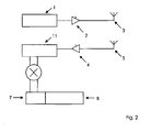
- FIG. 2 the construction of a first object A is shown, wherein the structure of a second object B can be displayed exactly the same.
- the shown first object A includes a transmission part A1 and a reception part A2.
- the transmitting part A1 consists of a first oscillator 1, an amplifier 2 and an antenna 3.
- the receiving part A2 includes a second oscillator 11, a phase mixer 6, an amplifier 4, a second antenna 5, an A / D converter 7, and a controller 8, moreover, the object A has a communication device not shown here the object A can communicate with an evaluation unit.
- the first oscillator 1 first generates a first synchronization signal.
- This synchronization signal of the first oscillator 1 is amplified by the first amplifier 2 and fed to the antenna 3, through which it is then radiated.
- This first signal is received by the second object B and also received by the first object A with the receiving part A2.
- the signal is received by the second antenna 5 and forwarded to an amplifier 4 on.
- the thus received signal is then evaluated with respect to a vibration of a second oscillator 11 with respect to the phase position.
- the phase comparison is achieved overall in that the signal generated by the double mixer 6 is converted by the analog-to-digital converter 7 and detected by the controller 8.
- the measurement results are then transmitted to an evaluation unit. There, an evaluation is then carried out on the basis of the measurement results, which then leads to the determination of a distance between the first object A and the second object B.
- the phase jitter of all participating oscillators is to be kept low.
- the maximum phase jitter is between one and three degrees. It is also important that all participating oscillators 1, 11 for the measuring period, each shown as measuring time t 2 , t 5 , generate a stable wave at a constant frequency. It is also possible, for example, to combine the antennas 3, 5 to form an antenna; in general, when choosing the arrangement of the antennas, however, care should be taken that the transmission channel between the antennas used for transmitting and receiving should be constant at an object.
- the embodiment provides two antennas on each object and thus simultaneous transmission and reception, it is immediately apparent that transmission and reception is not performed with the same components and is not required.
- the signal generated by the first oscillator 1 does not first radiate and receive again, ie to transmit and receive simultaneously, but to pick up this signal directly in front of or behind the amplifier 2 and to use it for evaluation.
- the arrangement chosen in the exemplary embodiment, in which the transmission and reception are simultaneous, only makes it particularly clear that the present method in no way relies on a coupling between the first oscillator 1 and the second oscillator 11.
- the individual groups, transmitting unit A1 and receiving unit A2 could thus theoretically be arranged separately even with a constant arrangement.
Abstract
Description
Die vorliegende Erfindung betrifft ein Verfahren zur Bestimmung einer Entfernung zwischen einem ersten und einem zweiten Objekt, mittels zwischen dem ersten und dem zweiten Objekt übertragender elektromagnetischer Wellen, umfassend folgende Verfahren zur:
- a) senden eines ersten Signals mit einer ersten Frequenz vom ersten Objekt aus
- b) empfangen des ersten Signals am zweiten Objekt
- c) senden eines zweiten Signals mit einer zweiten Frequenz vom zweiten Objekt aus
- d) empfangen des zweiten Signals am ersten Objekt
- e) ermitteln einer Frequenzdifferenz zwischen der ersten und der zweiten Frequenz und zur Verfügung stellen des Ergebnisses an eine Auswertungseinrichtung
- f) ermitteln einer ersten Phasendifferenz zwischen dem ersten Signal am ersten Objekt und dem zweiten Signal am ersten Objekt und zur Verfügung stellen des Ergebnisses an die Auswertungseinrichtung
- a) transmitting a first signal at a first frequency from the first object
- b) receiving the first signal at the second object
- c) transmitting a second signal at a second frequency from the second object
- d) receiving the second signal at the first object
- e) determine a frequency difference between the first and the second frequency and provide the result to an evaluation device
- f) determine a first phase difference between the first signal on the first object and the second signal on the first object and provide the result to the evaluation device
Solche Verfahren zur Bestimmung einer Entfernung zwischen einem ersten und einem zweiten Objekt sind aus dem Stand der Technik in verschiedener Ausgestaltung bekannt. So ist es beispielsweise bekannt, ein von einem ersten Objekt ausgestrahltes und an einem zweiten Objekt reflektiertes Signal zu verwenden, um die Phasenverschiebung zwischen dem ausgestrahlten und dem empfangenen Signal zu analysieren, um daraus die Entfernung zu bestimmen.Such methods for determining a distance between a first and a second object are known from the prior art in various embodiments. For example, it is known to use a signal emitted from a first object and reflected at a second object to analyze the phase shift between the transmitted and the received signal to determine the distance therefrom.
Des Weiteren ist es bekannt, von einem ersten Objekt ein erstes Signal abzustrahlen und an einem zweiten Objekt zu empfangen und ausgehend von diesem zweiten Objekt ein Signal abzustrahlen, dessen Phase in einer bestimmten Beziehung zu der Phase der am zweiten Objekt empfangenen Welle steht. Dieses zweite Signal wird dann wiederum am ersten Objekt empfangen und bezüglich der Phasendifferenz zur am ersten Objekt ausgestrahlten Welle analysiert. Daraus lässt sich dann die Entfernung zwischen den Objekten errechnen.Furthermore, it is known to radiate a first signal from a first object and to receive it at a second object and to radiate from this second object a signal whose phase is in a specific relationship to the phase of the wave received at the second object. This second signal is in turn received at the first object and analyzed for the phase difference to the wave emitted at the first object. From this the distance between the objects can be calculated.
Diese Verfahren sind jedoch mit zahlreichen Nachteilen behaftet. So führt die Verwendung eines lediglich am zweiten Objekt reflektierten Signals dazu, dass nur eine sehr geringe Signalstärke der reflektierten Welle zur Verfügung steht und das aufgrund der Reflektion an verschiedenen Objekten zahlreiche unterschiedliche Reflektionen auszuwerten sind.However, these methods have numerous disadvantages. Thus, the use of a signal reflected only on the second object means that only a very small signal strength of the reflected wave is available and that numerous different reflections are to be evaluated due to the reflection at different objects.
Wird ein Verfahren angewandt, bei dem am zweiten Objekt eine Welle abgestrahlt wird, deren Phase in einer festen Beziehung zu der Phase der am zweiten Objekt empfangenen ersten Welle steht, so besteht das Problem, dass am zweiten Objekt zeitgleich empfangen und gesendet wird. Dies führt zu zahlreichen Problemen, da sich die einzelnen Felder überlagern, was die Messung negativ beeinflusst beziehungsweise die Trennung der einzelnen Signale, die im gleichen Band liegen und zwar unter Umständen mit deutlich unterschiedlicher Stärke (Unterschiede von bis zu 100db sind keine Seltenheit), im Empfänger erschwert, teilweise sogar unmöglich macht. Des Weiteren ist die Erzeugung einer in der Phasenlage bestimmten Welle verhältnismäßig komplex und aufwendig.If a method is used in which a wave is radiated on the second object whose phase is in a fixed relationship to the phase of the first wave received at the second object, there is the problem that the second object is simultaneously received and transmitted. This leads to numerous problems, as the individual fields overlap, which negatively influences the measurement or the separation of the individual signals, which are in the same band and possibly with significantly different strength (differences of up to 100db are not uncommon) Receiver difficult, sometimes even impossible. Furthermore, the generation of a phase-wise wave is relatively complex and expensive.
Aus diesen Gründen wurden zahlreiche Verfahren entwickelt, die durch eine bestimmte Reihenfolge der Abstrahlung der verschiedenen Wellen versuchen, die Nachteile der einzelnen Verfahren möglichst gering zu halten. Dies führt jedoch im Allgemeinen zu einer größeren Komplexität der notwendigen Schaltungen und somit zu höheren Kosten und erhöhter Anfälligkeit bezüglich der Umwelteinflüsse, wie beispielsweise Reflexionen an anderen Objekten.For these reasons, numerous methods have been developed which try by a certain order of radiation of the different waves to minimize the disadvantages of the individual processes. However, this generally leads to greater complexity of the necessary circuitry and thus to higher costs and increased susceptibility to environmental influences, such as reflections on other objects.
Auch ist aus der
Diese Art der Abstandsbestimmung eignet sich auf Grund des vergleichsweise großen (absoluten) Fehlers insbesondere für Abstände von etwa 10 km und findet ihre Grenze der sinnvollen Anwendung im Bereich von einigen Metern. Darüber hinaus erfordert der zweite Signalrundlauf mehr Zeit und Energie als ein einzelner.This type of distance determination is due to the relatively large (absolute) error especially for distances of about 10 km and finds its limit of useful application in the range of a few meters. In addition, the second signal round trip requires more time and energy than a single one.
Aufgabe dieser Erfindung ist es somit, auf einfache Weise eine Entfernungsbestimmung zwischen zwei Objekten zu ermöglichen, die die Nachteile der aus dem Stand der Technik bekannten Verfahren vermeidet, insbesondere ohne Reflexion arbeitet, keine feste Phasenbeziehung zwischen ersten und zweiten Signalen und kein gleichzeitiges Senden und Empfangen erfordert und auch im cm-Abstandsbereich gute Auflösung ermöglicht und mit einem Signalrundlauf auskommt.It is thus an object of this invention to make it possible to easily determine the distance between two objects, which avoids the disadvantages of the prior art methods, in particular works without reflection, no fixed phase relationship between first and second signals and no simultaneous transmission and reception requires and in the CM distance range good resolution allows and manages with a signal circulation.
Diese Aufgabe wird gelöst durch ein Verfahren gemäß Anspruch 1 beziehungsweise durch eine Vorrichtung gemäß Anspruch 15. Die Unteransprüche 2 bis 14 geben vorteilhafte Weiterbildungen an.This object is achieved by a method according to claim 1 or by a device according to claim 15. The
Das erfindungsgemäße Verfahren zeichnet sich dadurch aus, dass zur Bestimmung der Entfernung zwischen einem ersten und einem zweiten Objekt mittels zwischen dem ersten und dem zweiten Objekt übertragender elektromagnetischer Wellen folgende Verfahrensschritte durchgeführt werden:
- a) senden eines ersten Signals mit einer ersten Frequenz vom ersten Objekt aus
- b) empfangen des ersten Signals am zweiten Objekt
- c) senden eines zweiten Signals mit einer zweiten Frequenz vom zweiten Objekt aus
- d) empfangen des zweiten Signal am ersten Objekt
- e) ermitteln einer Frequenzdifferenz zwischen der ersten und der zweiten Frequenz und zur Verfügung stellen des Ergebnisses an eine Auswertungseinrichtung
- f) ermitteln einer ersten Phasendifferenz zwischen dem ersten Signal am ersten Objekt und dem zweiten Signal am ersten Objekt und zur Verfügung stellen des Ergebnisses an die Auswertungseinrichtung,
- a) transmitting a first signal at a first frequency from the first object
- b) receiving the first signal at the second object
- c) transmitting a second signal at a second frequency from the second object
- d) receiving the second signal at the first object
- e) determine a frequency difference between the first and the second frequency and provide the result to an evaluation device
- f) determining a first phase difference between the first signal at the first object and the second signal at the first object and providing the result to the evaluation device,
Ein solches Verfahren basiert somit darauf dass ein erstes Signal vom ersten zum zweiten Objekt und ein zweites Signal vom zweiten zum ersten Objekt gesendet wird. Dabei ist jedoch die Phasenbeziehung zwischen dem ersten Signal und dem zweiten Signal vollkommen frei wählbar. Es ist lediglich erforderlich, dass diese Phasendifferenz ermittelt und zu der zur Bestimmung der Entfernung vorgesehenen Auswertungseinrichtung übermittelt wird. Dadurch ist es möglich, dieses Verfahren verhältnismäßig einfach zu realisieren. Denn die Ermittlung einer Phasendifferenz ist verhältnismäßig deutlich einfacher, als die Erzeugung eines Signals mit einer (relativ) vorbestimmten Phasenlage.Such a method is thus based on sending a first signal from the first to the second object and a second signal from the second to the first object. However, the phase relationship between the first signal and the second signal is completely freely selectable. It is only necessary that this phase difference is determined and transmitted to the evaluation device provided for determining the distance. This makes it possible to implement this method relatively easily. For the determination of a phase difference is relatively much easier than the generation of a signal with a (relatively) predetermined phase position.
Des Weiteren ist es dadurch möglich, ein gleichzeitiges Vorhandensein des ersten und des zweiten Signals an einem Objekt zu verhindern, wodurch Überlagerung der einzelnen Felder vermieden wird und beim Empfang eine bessere Dynamik erzielt werden kann. Aus diesem Grund kann beispielsweise auf stark richtende Antennen verzichtet werden und eine Entfernungsmessung auch noch bei deutlich schwächeren oder abgeschwächten Signalen des anderen Objekts durchgeführt werden. Des Weiteren kann auch die Empfindlichkeit beziehungsweise die Dynamik der Empfangsvorrichtungen reduziert werden, was zu einem Kostenvorteil führt und auch Energie einzusparen hilft. Auch ermöglicht dies, die Fehleranfälligkeit zu reduzieren bzw. die Genauigkeit der Bestimmung der Entfernung zu erhöhen.Furthermore, this makes it possible to prevent a simultaneous presence of the first and the second signal to an object, whereby superposition of the individual fields is avoided and the reception better dynamics can be achieved. For this reason, for example, can be dispensed with high-directivity antennas and a distance measurement even with significantly weaker or attenuated signals of the other object are performed. Furthermore, the sensitivity or the dynamics of the receiving devices can be reduced, which leads to a cost advantage and also helps to save energy. This also makes it possible to reduce the susceptibility to errors or to increase the accuracy of the determination of the distance.
Das erfindungsgemäße Verfahren kann theoretisch problemlos eine Auflösung von einem Grad bezüglich der Phase erreichen. In der Praxis werden mindestens 3 bis 12 Grad erzielbar sein. Dies entspricht bei einer bevorzugten Wellenlänge von etwa 12cm einer Genauigkeit von 1 bis 4mm.The inventive method can theoretically easily achieve a resolution of one degree with respect to the phase. In practice, at least 3 to 12 degrees will be achievable. This corresponds to a preferred wavelength of about 12cm accuracy of 1 to 4mm.
Dabei ist das erfindungsgemäße Verfahren keineswegs auf einen bestimmten Wellenlängenbereich oder eine Polarisation festgelegt. Vielmehr kann dieses Verfahren in einem beliebigen Wellenlängenbereich durchgeführt werden. Auch kann die Übermittlung der mindestens einen zweiten Phasendifferenz zwischen je einem ersten Signal am zweiten Objekt und je einem zweiten Signal am zweiten Objekt an die Auswertungseinrichtung auf jede beliebige Art und Weise erfolgen. In Frage kommen beispielsweise eine Übertragung per Funk, Infrarot oder eine Verkabelung.In this case, the method according to the invention is by no means fixed to a specific wavelength range or polarization. Rather, this method can be performed in any wavelength range. Also, the transmission of the at least one second phase difference between a respective first signal at the second object and a respective second signal at the second object to the evaluation device can take place in any desired manner. In question, for example, a transmission by radio, infrared or cabling.
Durch unterschiedliche, insbesondere wechselnde, Ausrichtung der Antennen und insbesondere beim Einsatz von stark unterschiedlichen Frequenzen, kann es zu einer Beeinträchtigung des Messergebnisses durch eine Beeinflussung der Phasendifferenzbestimmung durch die Antennen kommen. Dieses Problem kann beispielsweise dadurch verringert, beziehungsweise verhindert werden, dass die (relative) Ausrichtung der Antennen erfasst wird, beziehungsweise konstant gehalten wird und/oder der Phasengang jeder verwendeten Antennen in Abhängigkeit von der Frequenz berücksichtigt wird.By different, in particular changing, alignment of the antennas and in particular when using very different frequencies, there may be an impairment of the measurement result by influencing the phase difference determination by the antennas. This problem can be reduced or prevented, for example, by the fact that the (relative) orientation of the antennas is detected or kept constant and / or the phase response of each antenna used as a function of the frequency is taken into account.
Zur Erhöhung der Genauigkeit oder der Fehlertoleranz können die Verfahrensschritte a) bis f) beliebig oft durchlaufen werden. Dabei kann die Wiederholung bei unterschiedlichen ersten und/oder zweiten Frequenzen durchgeführt werden, was die Eindeutigkeit bzw. die Genauigkeit weiter erhöht. Vorteilhafterweise werden genau so viele zweite Phasendifferenzen zwischen je einem ersten Signal am zweiten Objekt und je einem zweiten Signal am zweiten Objekt übertragen, wie die Häufigkeit der Durchläufe der Verfahrensschritte a) bis f) beträgt.To increase the accuracy or the error tolerance, the method steps a) to f) can be run as often as desired. In this case, the repetition can be carried out at different first and / or second frequencies, which further increases the uniqueness or the accuracy. Advantageously, exactly as many second phase differences are transmitted between a respective first signal on the second object and a second signal on the second object, as is the frequency of the passages of method steps a) to f).
Die Auswertungseinrichtung kann sowohl am ersten Objekt oder am zweiten Objekt oder an einem beliebigen anderen Ort angeordnet sein. Sie kann auch in einem der Objekte integriert sein. Auch kann die Auswertungseinrichtung in verschiedene Teile unterteilt werden und somit an unterschiedlichen örtlichen Positionen angeordnet werden. Dabei teilen sich dann die einzelnen Teile der Auswertungseinrichtung die Auswertungsschritte oder führen einige oder alle Auswertungsschritte mehrfach durch. Die Auswertung erfolgt nach bekannten physikalischen Gesetzmäßigkeiten. Dabei wird in der Auswertungseinrichtung in der Regel zunächst die Signallaufzeit ermittelt, aus der dann verhältnismäßig einfach die Entfernung errechnet werden kann, wenn das Medium, in dem die Messungen durchgeführt worden sind, bekannt ist.The evaluation device can be arranged both on the first object or on the second object or at any other location. It can also be integrated in one of the objects. Also, the evaluation device can be divided into different parts and thus arranged at different local positions. In this case, the individual parts of the evaluation device then share the evaluation steps or carry out some or all of the evaluation steps several times. The evaluation is carried out according to known physical laws. In this case, in the evaluation device usually first the signal propagation time determined, from which then the distance can be calculated relatively easily, if the medium in which the measurements have been carried out, is known.
Vorteilhafterweise wird die Bestimmung der Phasendifferenzen innerhalb, in Bezug auf einen ersten Referenzzeitpunkt, vorbestimmten Zeiträumen durchgeführt. Dies ermöglicht es, eine höhere Genauigkeit zu erzielen. Je kleiner diese Zeitintervalle bemessen sind, umso höher ist die erzielbare Genauigkeit, aus welchem Grund es besonders vorteilhaft ist, wenn diese Zeiträume als Zeitpunkte definiert werden.Advantageously, the determination of the phase differences is performed within, with respect to a first reference time, predetermined time periods. This makes it possible to achieve higher accuracy. The smaller these time intervals are dimensioned, the higher the achievable accuracy, for which reason it is particularly advantageous if these time periods are defined as times.
Besonders vorteilhaft ist es, da sich dadurch besonders genaue Ergebnisse produzieren lassen, wenn das Produkt aus jedem der Zeiträume multipliziert mit der Differenz zwischen der entsprechenden ersten und zweiten Frequenz nicht größer ist als das Dreifache der zu erzielenden Messgenauigkeit der Phasendifferenzbestimmung.It is particularly advantageous, since it allows particularly accurate results to be produced if the product of each of the periods multiplied by the difference between the corresponding first and second frequencies is not greater than three times the accuracy of measurement of the phase difference determination to be achieved.
Bei dem Produkt aus den Zeiträumen jeweils multipliziert mit der Differenz zwischen der entsprechenden ersten und zweiten Frequenz handelt es sich um den Phasenfehler, also um den Fehler, der bei der Bestimmung der Phasenlage zwischen erstem und zweitem Signal in Kauf genommen werden muss. Die zu erzielende Messgenauigkeit bezüglich der Phasendifferenzbestimmung ergibt sich zwangsläufig aus der avisierten Genauigkeit der Bestimmung der Entfernung zwischen dem ersten und dem zweiten Objekt.The product of the periods respectively multiplied by the difference between the corresponding first and second frequencies is the phase error, ie the error which has to be accepted when determining the phase position between the first and second signal. The measurement accuracy to be achieved with respect to the phase difference determination necessarily results from the intended accuracy of the determination of the distance between the first and the second object.
Als besonders vorteilhaft hat es sich erwiesen, wenn dieser Phasenfehler nicht größer ist als 0,04 und wenn insbesondere die Differenz zwischen der entsprechenden ersten und zweiten Frequenz nicht größer ist als 0,0001 Promille in Bezug auf die erste Frequenz und insbesondere nicht größer ist als 500Hz.It has proven to be particularly advantageous if this phase error is not greater than 0.04 and, in particular, if the difference between the corresponding first and second frequencies is not greater than 0.0001 parts per thousand with respect to the first frequency and, in particular, not greater than 500Hz.
Besonders vorteilhaft ist es, wenn gemäß Anspruch 4 das zweite Signal erst gesendet wird, wenn das erste Signal am zweiten Objekt ausgeklungen ist, das heißt dessen Feldstärke also zumindest deutlich kleiner ist als die maximale Feldstärke des ersten Signals am zweiten Objekt, insbesondere nur noch weniger als 5% dieser maximalen Feldstärke aufweist.It is particularly advantageous if, according to claim 4, the second signal is sent only when the first signal at the second object has faded out, that is, whose field strength is at least significantly smaller than the maximum field strength of the first signal on the second object, in particular only less than 5% of this maximum field strength.
Bei einer solchen Ausgestaltung wird eine Überlagerung der Felder des ersten und des zweiten Signals vermieden, was zu einer Erhöhung der möglichen Genauigkeit beziehungsweise zu der Möglichkeit der Reduktion der Empfängerdynamik und/oder -empfindlichkeit bzw. der Erhöhung der Empfangsempfindlichkeiten führt.In such an embodiment, a superposition of the fields of the first and the second signal is avoided, which leads to an increase in the possible accuracy or to the possibility of reducing the receiver dynamics and / or sensitivity or increasing the reception sensitivities.
Bevorzugt wird es, wenn gemäß Anspruch 5 die Verfahrensschritte a) bis f) n-mal durchlaufen werden, wobei n die Anzahl der Wiederholungen mindestens 2 beträgt. Vorteilerhafterweise werden diese Wiederholungen mit unterschiedlichen ersten und unterschiedlichen zweiten Frequenzen durchgeführt, wobei vorteilerhafterweise mindestens 2 zweite, insbesondere n-zweite, Phasendifferenzen zwischen je einem ersten Signal am zweiten Objekt und je einem zweiten Signal am zweiten Objekt ermittelt und an die Auswertungseinrichtung übertragen und bei der Ermittlung der Entfernung verwendet werden. Die Wiederholung der Verfahrensschritte a) bis f) und die Übertragung von mehreren zweiten Phasendifferenzen führt zu einer Erhöhung der möglichen Genauigkeit. Dies beruht auf der Reduktion von Messfehlern durch statistische Auswertung beziehungsweise auf der Möglichkeit verschiedene Ausbreitungswege voneinander zu unterscheiden. Die lässt sich besonders gut realisieren, wenn bei den einzelnen Durchläufen unterschiedliche erste und unterschiedliche zweite Frequenzen verwendet werden. Besonders vorteilhaft ist es dabei genau so viele zweite Phasendifferenzen zu ermitteln und zu übertragen, wie die Verfahrensschritte a) bis f) durchlaufen werden. In diesem Fall erhält man pro einer ersten und einer zweiten Frequenz jeweils eine erste und eine zweite Phasendifferenz. Dies ermöglicht eine besonders gute Auswertung der Messergebnisse bezüglich der Entfernung zwischen dem ersten und dem zweiten Objekt.It is preferred if, according to
Vorteilhaft ist es, wenn gemäß Anspruch 6 zur Ermittlung der Entfernung die Veränderung der Phasendifferenzen in Abhängigkeit von der Veränderung der Summe aus der entsprechenden ersten und zweiten Frequenz ermittelt wird. Zwar ist eine Ermittlung der Entfernung auch möglich, ohne diese Abhängigkeit zu berücksichtigen, doch kann durch die Berücksichtigung dieser Abhängigkeit eine besonders hohe Genauigkeit erreicht werden beziehungsweise eine besonders gute Vermeidung von Messergebnisverfälschungen aufgrund von Umwelteinflüssen, wie zusätzlichen Reflektionen, realisiert werden. Bevorzugt wird es, gemäß Anspruch 7 das Senden der ersten und/oder zweiten Signale innerhalb in Bezug auf einen zweiten Referenzzeitpunkt vorbestimmter Zeitintervalle, insbesondere Zeitintervalle von nicht mehr als 60µs, zu beginnen. Die möglichst genaue Festlegung des Starts der Ausstrahlung der ersten und/oder zweiten Signale kann dazu verwendet werden, dass jeweils empfangende Objekt so einzustellen bzw. die dort empfangenen Daten so vor auszuwerten, dass eine besonders genaue Bestimmung der Parameter, wie beispielsweise der relativen Phasenlage, möglich ist. Dadurch kann die Genauigkeit der Messung gesteigert werden. Besonders vorteilhaft ist es, wenn die Zeitintervalle, in der das Senden der ersten und/oder zweiten Signale begonnen wird auch in Bezug auf den Referenzzeitpunkt gemäß Anspruch 2 vorbestimmt sind. Dies ermöglicht eine weitere Steigerung der Genauigkeit der Entfernungsbestimmung.It is advantageous if, according to claim 6 for determining the distance, the change of the phase differences in dependence on the change in the sum of the corresponding first and second frequencies is determined. Although a determination of the distance is also possible without taking into account this dependency, a particularly high accuracy can be achieved by taking account of this dependency or a particularly good avoidance of measurement result distortions due to environmental influences, such as additional reflections, can be realized. It is preferred, according to
Vorteilhaft kann es sein, wenn gemäß Anspruch 8 die ersten und zweiten Signale zueinander am zweiten Objekt nicht phasengleich sind. Zunächst kann ein erfindungsgemäßes Verfahren auf die Phasenübereinstimmung ohne Einbußen bezüglich der Messgenauigkeit verzichten. Des Weiteren kann durch einen Verzicht auf die Phasenübereinstimmung eine deutliche Vereinfachung der Erzeugung des zweiten Signals erreicht werden. In diesem Fall kann es natürlich vorkommen, dass die Signale zufällig bezüglich der Phase übereinstimmen. Darüber hinaus können durch eine Vermeidung der Phasenübereinstimmung negative Beeinflussungen der beiden Signale untereinander verringert bzw. vermieden werden.It may be advantageous if according to claim 8, the first and second signals to each other on the second object are not in phase. First, a method according to the invention can dispense with phase matching without sacrificing measurement accuracy. Furthermore, a significant simplification of the generation of the second signal can be achieved by dispensing with the phase match. In this case, of course, the signals may coincidentally coincide in phase. In addition, by avoiding the phase coincidence negative influences of the two signals can be reduced or avoided.
Vorteilerhafterweise wird die Auswertungselektronik gemäß Anspruch 9 am ersten Objekt angeordnet. Im erfindungsgemäßen Verfahren wird die Bestimmung der Entfernung durch das Senden vom ersten Objekt aus begonnen. Aus diesem Grund kann es vorteilhaft sein, die Auswertungseinrichtung am oder innerhalb des ersten Objektes anzuordnen. Bei einer solchen Anordnung kann die Bestimmung der Entfernung dann auf einfache Weise auch durch die Auswerteeinrichtung initiiert werden.Vorteilerhafterweise the evaluation electronics according to
Vorteilhafterweise wird der Verfahrensschritt e), die Ermittlung der Frequenzdifferenz zwischen der ersten und der zweiten Frequenz und das zur Verfügung stellen des Ergebnisses an einer Auswertungseinrichtung am ersten Objekt durchgeführt. Zwar ist es generell möglich diesen Verfahrensschritt an jedem oder an beiden Objekten durchzuführen, doch kann es besonders vorteilhaft sein, insbesondere dann, wenn auch die Auswertungseinrichtung am ersten Objekt angeordnet ist, diesen Verfahrensschritt e) am oder im ersten Objekt durchzuführen. Dadurch kann es möglich sein, die Übertragung an die Auswerteeinrichtung zu vereinfachen oder gegen Umwelteinflüsse besser zu sichern.Advantageously, the method step e), the determination of the frequency difference between the first and the second frequency and the provision of the result at an evaluation device on the first object are performed. Although it is generally possible to carry out this method step on each or both objects, it may be particularly advantageous, especially if the evaluation device is arranged on the first object, this Process step e) on or in the first object to perform. This may make it possible to simplify the transmission to the evaluation or better secure against environmental influences.
Besonders vorteilhaft kann es sein, zu mindestens eine Amplitude mit der ein erstes Signal am zweiten Objekt bzw. mit der ein zweites Signal am ersten Objekt empfangen wird an die Auswerteeinrichtung zu übertragen. Dadurch kann es möglich sein, eine höhere Genauigkeit bezüglich der Bestimmung der Entfernung zu erzielen, wenn eine Signalausbreitung auf mehreren Wegen möglich ist. Dies kann beispielsweise durch Reflektionen an weiteren Objekten der Fall sein.It can be particularly advantageous to transmit to at least one amplitude with which a first signal at the second object or with which a second signal is received at the first object to the evaluation device. As a result, it may be possible to achieve a higher accuracy with respect to the determination of the distance, if a signal propagation in several ways is possible. This can be the case for example by reflections on other objects.
Besonders vorteilhaft ist es gemäß Anspruch 12, wenn die Übertragung an die Auswerteeinrichtung unabhängig von dem ersten und dem zweiten Signal geschieht. Durch eine solche Wahl der separaten Übertragung kann eine höhere Genauigkeit erzielt werden, da die Übertragung von Informationen die Genauigkeit der Analyse der Entfernung bzw. der einzelnen Signale beeinträchtigt. Besonders vorteilhaft kann es sein, die Übertragung an die Auswertungseinrichtung über elektromagnetische Wellen durchzuführen.It is particularly advantageous according to claim 12, when the transmission to the evaluation device is independent of the first and the second signal. By such a choice of separate transmission, a higher accuracy can be achieved, since the transmission of information affects the accuracy of the analysis of the distance or of the individual signals. It may be particularly advantageous to carry out the transmission to the evaluation device via electromagnetic waves.
Besonders vorteilhaft kann es sein, wenn die erste Frequenz jeweils, also bei jedem Durchlauf der Verfahrensschritte a) bis f), ungleich der jeweiligen zweiten korrespondierenden Frequenz ist. Dadurch lassen sich Umwelteinflüsse und die Beeinflussung der einzelnen Signale untereinander verringern.It may be particularly advantageous if the first frequency in each case, that is, in each pass of the method steps a) to f), is not equal to the respective second corresponding frequency. As a result, environmental influences and the influence of the individual signals with each other can be reduced.
Bevorzugterweise werden die ersten und zweiten Frequenzen so gewählt, dass sie innerhalb eines Frequenzintervalls von 2000 MHz bis 3000 MHz und/oder von 4 GHz bis 6 GHz, insbesondere innerhalb von 2400 MHz bis 2483,5 MHz und/oder von 4,9 GHz bis 5,875 GHz liegen. Diese Bereiche sind besonders geeignet, um das erfindungsgemäße Verfahren durchzuführen. Des Weiteren sind in diesen Bereichen RFID-Anwendungen anzutreffen, bei denen eine Bestimmung der Entfernung zwischen einzelnen Objekten auf besonders einfache Weise von besonders hoher Bedeutung ist. Dies basiert darauf, dass in RFID häufig nur wenig Energie und wenig Raum zur Verfügung steht und die einzelnen Objekte verhältnismäßig einfach zu produzieren sein müssen. Eine Bestimmung der Entfernung zwischen den einzelnen RFID-Objekten ist darüber hinaus von großer Bedeutung, da dadurch Prozesse besonders effizient gesteuert werden können.Preferably, the first and second frequencies are chosen to be within a frequency interval of 2000 MHz to 3000 MHz and / or from 4 GHz to 6 GHz, in particular within 2400 MHz to 2483.5 MHz and / or from 4.9 GHz to 5.875 GHz lie. These ranges are particularly suitable for carrying out the method according to the invention. Furthermore, RFID applications are found in these areas, in which a determination of the distance between individual objects is particularly important in a particularly simple manner. This is based on the fact that in RFID often only little energy and little space is available and the individual objects must be relatively easy to produce. A determination of the distance between the individual In addition, RFID objects are of great importance, since processes can be controlled particularly efficiently.
Die erfindungsgemäße Vorrichtung beinhaltet ein erstes und zweites Objekt umfassend jeweils Mittel zum Senden und Empfangen von elektromagnetischen Wellen und Steuervorrichtungen zum Durchführen eines Verfahrens gemäß einer der Ansprüche 1 bis 14 sowie umfassend mindestens eine Auswerteeinheit und Mittel zur Übertragung der an die Auswerteeinheit verfahrungsgemäß zu übertragenden Mess- und/oder Berechnungsergebnisse.The device according to the invention comprises a first and a second object each comprising means for transmitting and receiving electromagnetic waves and control devices for carrying out a method according to one of claims 1 to 14, and comprising at least one evaluation unit and means for transmitting the measuring points to be transmitted to the evaluation unit according to the method. and / or calculation results.
Weitere Vorteile und Ausgestaltungsmöglichkeiten der vorliegenden Erfindungen sollen im Folgenden anhand eines Ausführungsbeispieles geschildert werden. Das Ausführungsbeispiel ist jedoch rein schematisch und keineswegs beschränkend. Auch lassen sich weitere Ausführungsformen durch den Fachmann leicht auffinden und an die gegebenen Anforderungen anpassen.Further advantages and design options of the present invention will be described below with reference to an embodiment. However, the embodiment is purely schematic and not restrictive. Also, other embodiments can be easily found by the skilled person and adapted to the given requirements.
Die Schilderung orientiert sich dabei an den rein schematischen und skizzenhaften Figuren. Die Figuren zeigen im Einzelnen:
- Fig. 1:
- schematische Darstellung des Verfahrensablaufs
- Fig. 2:
- schematischer Aufbau eines Objekts.
- Fig. 1:
- schematic representation of the procedure
- Fig. 2:
- schematic structure of an object.
In
Der Empfangsteil A2 beinhaltet einen zweiten Oszillator 11, einen Phasenmischer 6, einen Verstärker 4, eine zweite Antenne 5, einen A/D-Wandler 7 und einen Controller 8, darüber hinaus weist das Objekt A eine Kommunikationsvorrichtung, hier nicht gezeigt, auf, mit der das Objekt A mit einer Auswerteeinheit kommunizieren kann.The receiving part A2 includes a
In Bezug auf das in
Dies geschieht mit Hilfe eines Doppelmischers 6, in dem die beiden Signale, das empfangene und das durch den zweiten Oszillator 11 erzeugte, zeitversetzt auf eine Zwischenfrequenz runter gemischt und die Phasenlage in der Zwischenfrequenz betrachtet und auf einen gemeinsamen Zeitpunkt hochgerechnet.This is done with the aid of a double mixer 6, in which the two signals, the received and generated by the
Der gleiche Empfangsvorgang, bei dem dann aber als empfangenes Signal das vom zweiten Objekt B abgestrahlte zweite Signal mit dem Signal des zweiten Oszillators 11 des ersten Objekts A verglichen wird, wird im Objekt A durchgeführt, wenn das zweite Objekt B ein zweites Signal ausstrahlt.The same reception process, in which, however, as the received signal, the second signal radiated by the second object B is then compared with the signal of the
Analoge Vorgänge, abgesehen von Synchronisationssignalen, finden im zweiten Objekt B statt.Analogous operations, apart from synchronization signals, take place in the second object B.
Der Phasenvergleich wird dabei insgesamt dadurch erreicht, dass das durch den Doppelmischer 6 erzeugte Signal durch den Analog-Digital-Wandler 7 umgewandelt und vom Controller 8 erfasst wird. Die Messergebnisse werden dann an eine Auswertungseinheit übertragen. Dort wird dann auf Basis der Messergebnisse eine Auswertung durchgeführt, die dann zu der Ermittlung einer Entfernung zwischen dem ersten Objekt A und dem zweiten Objekt B führt.The phase comparison is achieved overall in that the signal generated by the double mixer 6 is converted by the analog-to-
Weitere Abwandlungen dieses Ausführungsbeispieles und Anpassung an die jeweils konkret gestellte Aufgabe sind durch den Fachmann leicht aufzufinden. So ist beispielsweise sofort ersichtlich, dass die Oszillatoren 1 und 11 in einem einzigen Oszillator zusammengefasst werden können, um Bauteile zu sparen. Allerdings ist eine Kopplung zwischen den Oszillatoren 1 und 11 nicht notwendig.Further modifications of this embodiment and adaptation to the particular concrete task are easily found by the skilled person. For example, it is immediately apparent that the
Generell ist der Phasenjitter aller beteiligten Oszillatoren gering zu halten. In dem hier gezeigten Ausführungsbeispiel liegt der maximale Phasenjitter zwischen ein und drei Grad. Wichtig ist des Weiteren, dass alle beteiligten Oszillatoren 1, 11 für den Messzeitraum, je als Messzeitpunkt t2, t5 dargestellt, auf einer konstanten Frequenz eine stabile Welle erzeugen. Auch können beispielsweise die Antennen 3, 5 zu einer Antenne zusammengefasst werden, generell ist bei der Wahl der Anordnung der Antennen jedoch darauf zu achten, dass der Übertragungskanal zwischen den zum Senden und Empfangen verwendeten Antennen an einem Objekt konstant sein soll.In general, the phase jitter of all participating oscillators is to be kept low. In the embodiment shown here, the maximum phase jitter is between one and three degrees. It is also important that all participating
Dies ist beispielsweise in der Regel dann gegeben wenn zwei dicht beieinander liegende Antennen 3, 5 verwendet werden.This is usually the case, for example, when two closely spaced
Auch wenn das Ausführungsbeispiel an jedem Objekt zwei Antennen vorsieht und somit ein gleichzeitiges Senden und Empfangen erfolgt, so ist doch sofort ersichtlich, dass das Senden und Empfangen nicht mit den gleichen Bauteilen durchgeführt wird und auch nicht erforderlich ist. So wäre es problemlos möglich, dass vom ersten Oszillator 1 erzeugte Signal nicht erst abzustrahlen und wieder zu empfangen, also gleichzeitig zu senden und zu empfangen, sondern dieses Signal direkt vor oder hinter dem Verstärker 2 abzugreifen und zur Auswertung zu verwenden. Die im Ausführungsbeispiel gewählte Anordnung, bei der gleichzeitig gesendet und empfangen wird, macht nur besonders gut deutlich, dass das vorliegende Verfahren auf eine Kopplung zwischen dem ersten Oszillator 1 und dem zweiten Oszillator 11 in keiner Weise angewiesen ist. Die einzelnen Gruppen, Sendeeinheit A1 und Empfangseinheit A2 könnten somit theoretisch sogar bei konstanter Anordnung voneinander getrennt angeordnet werden.Although the embodiment provides two antennas on each object and thus simultaneous transmission and reception, it is immediately apparent that transmission and reception is not performed with the same components and is not required. Thus, it would be easily possible that the signal generated by the first oscillator 1 does not first radiate and receive again, ie to transmit and receive simultaneously, but to pick up this signal directly in front of or behind the
- AA
- erstes Objektfirst object
- BB
- zweites Objektsecond object
- A1A1
- Sendeteil des ersten ObjektsTransmitting part of the first object
- A2A2
- Empfangsteil des ersten ObjektsReceiving part of the first object
- 11
- erster Oszillatorfirst oscillator
- 22
- erster Verstärkerfirst amplifier
- 33
- erste Antennefirst antenna
- 44
- zweiter Verstärkersecond amplifier
- 55
- zweite Antennesecond antenna
- 66
- Doppelmischerdouble mixer
- 77
- Analog-Digital-WandlerAnalog to digital converter
- 88th
- Controllercontroller
- 99
- Synchronisationsynchronization
- 1010
- Wiederholungrepeat
- 1111
- zweiter Oszillatorsecond oscillator
- t0 t 0
- SynchronisationszeitpunktSynchronization time
- t1 t 1
- Beginn der Abstrahlung des ersten SignalsStart of the radiation of the first signal
- t2 t 2
- Messzeitpunkt des ersten SignalsMeasuring time of the first signal
- t3 t 3
- Ende der Abstrahlung des ersten SignalsEnd of the radiation of the first signal
- t4 t 4
- Beginn der Abstrahlung des zweiten SignalsStart of the radiation of the second signal
- t5 t 5
- Messzeitpunkt des zweiten SignalsMeasuring time of the second signal
- t6 t 6
- Ende der Abstrahlung des zweiten SignalsEnd of the radiation of the second signal
Claims (15)
dadurch gekennzeichnet, dass
mindestens eine zweite Phasendifferenzen zwischen je einem ersten Signal am zweiten Objekt und je einem zweiten Signal am zweiten Objekt ermittelt und an die Auswertungseinrichtung übertragen und bei der Ermittlung der Entfernung verwendet werden.Method for determining a distance between a first object (A) and a second object (B) by means of electromagnetic waves transmitted between the first and the second object, comprising the following method steps:
characterized in that
at least one second phase difference between a respective first signal on the second object and a second signal on the second object is determined and transmitted to the evaluation device and used in the determination of the distance.
Priority Applications (2)
| Application Number | Priority Date | Filing Date | Title |
|---|---|---|---|
| EP08021604A EP2196823B1 (en) | 2008-12-12 | 2008-12-12 | Method for determining the distance between two objects |
| AT08021604T ATE513229T1 (en) | 2008-12-12 | 2008-12-12 | METHOD FOR DETERMINING THE DISTANCE BETWEEN TWO OBJECTS |
Applications Claiming Priority (1)
| Application Number | Priority Date | Filing Date | Title |
|---|---|---|---|
| EP08021604A EP2196823B1 (en) | 2008-12-12 | 2008-12-12 | Method for determining the distance between two objects |
Publications (2)
| Publication Number | Publication Date |
|---|---|
| EP2196823A1 true EP2196823A1 (en) | 2010-06-16 |
| EP2196823B1 EP2196823B1 (en) | 2011-06-15 |
Family
ID=40551961
Family Applications (1)
| Application Number | Title | Priority Date | Filing Date |
|---|---|---|---|
| EP08021604A Active EP2196823B1 (en) | 2008-12-12 | 2008-12-12 | Method for determining the distance between two objects |
Country Status (2)
| Country | Link |
|---|---|
| EP (1) | EP2196823B1 (en) |
| AT (1) | ATE513229T1 (en) |
Cited By (5)
| Publication number | Priority date | Publication date | Assignee | Title |
|---|---|---|---|---|
| WO2012155992A1 (en) | 2011-05-18 | 2012-11-22 | Lambda:4 Entwicklungen Gmbh | Method to improve a distance measurement between moving objects |
| EP3564706A1 (en) | 2018-05-04 | 2019-11-06 | Lambda: 4 Entwicklungen GmbH | Method and system for high resolution range and velocity measurements |
| EP3564707A1 (en) * | 2018-05-04 | 2019-11-06 | Lambda: 4 Entwicklungen GmbH | Method and system for high resolution range and velocity measurements |
| EP3722831A1 (en) | 2019-04-10 | 2020-10-14 | Stichting IMEC Nederland | Method of wireless ranging |
| EP3635992B1 (en) | 2017-09-15 | 2021-04-14 | Metirionic GmbH | Method for radio measuring applications |
Citations (3)
| Publication number | Priority date | Publication date | Assignee | Title |
|---|---|---|---|---|
| WO2002073562A1 (en) * | 2001-03-12 | 2002-09-19 | Eureka Technologies Partners, Llc | Article locator system |
| WO2004035357A2 (en) * | 2002-10-12 | 2004-04-29 | Conti Temic Microelectronic Gmbh | Method for determining the distance between a first and second transmitting and receiving station |
| EP1815267A1 (en) | 2004-11-15 | 2007-08-08 | Nanotron Technologies GmbH | Symmetrical multipath method for determining the distance between two transceivers |
Family Cites Families (2)
| Publication number | Priority date | Publication date | Assignee | Title |
|---|---|---|---|---|
| AT407800B (en) * | 1999-08-16 | 2001-06-25 | Gerhard Dr Leuchs | INTERFEROMETRIC DEVICE FOR MEASURING THE POSITION OF A REFLECTIVE OBJECT |
| US6744398B1 (en) * | 2002-04-19 | 2004-06-01 | Derek J. Pyner | Distancing and positioning systems and methods |
-
2008
- 2008-12-12 AT AT08021604T patent/ATE513229T1/en active
- 2008-12-12 EP EP08021604A patent/EP2196823B1/en active Active
Patent Citations (3)
| Publication number | Priority date | Publication date | Assignee | Title |
|---|---|---|---|---|
| WO2002073562A1 (en) * | 2001-03-12 | 2002-09-19 | Eureka Technologies Partners, Llc | Article locator system |
| WO2004035357A2 (en) * | 2002-10-12 | 2004-04-29 | Conti Temic Microelectronic Gmbh | Method for determining the distance between a first and second transmitting and receiving station |
| EP1815267A1 (en) | 2004-11-15 | 2007-08-08 | Nanotron Technologies GmbH | Symmetrical multipath method for determining the distance between two transceivers |
Non-Patent Citations (1)
| Title |
|---|
| MIZUI K ET AL: "Vehicle-to-vehicle 2-way communication and ranging system using spread spectrum technique: proposal of double boomerang transmission system", VEHICLE NAVIGATION AND INFORMATION SYSTEMS CONFERENCE, 1994. PROCEEDIN GS., 1994 YOKOHAMA, JAPAN 31 AUG.-2 SEPT. 1994, NEW YORK, NY, USA,IEEE, 31 August 1994 (1994-08-31), pages 153 - 158, XP010136540, ISBN: 978-0-7803-2105-2 * |
Cited By (15)
| Publication number | Priority date | Publication date | Assignee | Title |
|---|---|---|---|---|
| EP3187893A1 (en) | 2011-05-18 | 2017-07-05 | Lambda: 4 Entwicklungen GmbH | Method to determine the location of a receiver |
| WO2012155990A1 (en) | 2011-05-18 | 2012-11-22 | Lambda:4 Entwicklungen Gmbh | Method to determine the location of a receiver |
| US9215563B2 (en) | 2011-05-18 | 2015-12-15 | Lambda:4 Entwicklungen Gmbh | Method to determine the location of a receiver |
| US9341702B2 (en) | 2011-05-18 | 2016-05-17 | Lambda:4 Entwicklungen Gmbh | Method of distance measurement |
| US9658317B2 (en) | 2011-05-18 | 2017-05-23 | Lambda:4 Entwicklungen Gmbh | Method for distance measurement between moving objects |
| WO2012155991A1 (en) | 2011-05-18 | 2012-11-22 | Lambda:4 Entwicklungen Gmbh | Method for fast and accurate distance measurement |
| US9945930B2 (en) | 2011-05-18 | 2018-04-17 | Lambda:4 Entwicklungen Gmbh | System and method for determining an orientation or position of a receiver relative to an emission device |
| WO2012155992A1 (en) | 2011-05-18 | 2012-11-22 | Lambda:4 Entwicklungen Gmbh | Method to improve a distance measurement between moving objects |
| EP3635992B1 (en) | 2017-09-15 | 2021-04-14 | Metirionic GmbH | Method for radio measuring applications |
| EP3643104B1 (en) | 2017-09-15 | 2021-06-16 | Metirionic GmbH | Method for radio measuring applications |
| EP3564706A1 (en) | 2018-05-04 | 2019-11-06 | Lambda: 4 Entwicklungen GmbH | Method and system for high resolution range and velocity measurements |
| CN110440849A (en) * | 2018-05-04 | 2019-11-12 | 拉姆达4发展有限公司 | Method and system for high-resolution distance and tachometric survey |
| EP3564707A1 (en) * | 2018-05-04 | 2019-11-06 | Lambda: 4 Entwicklungen GmbH | Method and system for high resolution range and velocity measurements |
| US11175396B2 (en) | 2018-05-04 | 2021-11-16 | Lambda: 4 Entwicklungen Gmbh | Method and system for high resolution range and speedometers |
| EP3722831A1 (en) | 2019-04-10 | 2020-10-14 | Stichting IMEC Nederland | Method of wireless ranging |
Also Published As
| Publication number | Publication date |
|---|---|
| EP2196823B1 (en) | 2011-06-15 |
| ATE513229T1 (en) | 2011-07-15 |
Similar Documents
| Publication | Publication Date | Title |
|---|---|---|
| EP1340097B1 (en) | Radar device and method for operating a radar device | |
| DE19922411A1 (en) | Radar measurement of distances, relative speeds between vehicle, obstruction(s) involves computing intercepts of all lines from 2 chirps at 2 frequency positions in distance-speed diagram | |
| EP0535196B1 (en) | Process and arrangement for retroreflective measurement of distance | |
| EP1185881B1 (en) | Distance measuring device and method for calibrating a distance measuring device | |
| EP3308110B1 (en) | Method and device for testing the functionality of a radar-based fill state measuring device | |
| EP2406659B1 (en) | Distance measurement | |
| EP2101278A2 (en) | Compensation circuit for an RFID reader unit and RFID reader unit | |
| DE102015006032B4 (en) | Ultrasonic detection device and detection method therefor | |
| EP1380854A2 (en) | Method and radar system for determining the direction angle of radar objects | |
| EP2196823B1 (en) | Method for determining the distance between two objects | |
| DE102017105783B4 (en) | Method for determining a distance and a speed of an object | |
| EP1763653B1 (en) | Method and device for determining the thickness of material on the basis of high frequencies | |
| DE102015107419A1 (en) | radar device | |
| DE19538309A1 (en) | Radar method for measuring distances and relative speeds between a vehicle and one or more obstacles | |
| DE2542628A1 (en) | RADAR FOR DISTANCE MEASUREMENT | |
| DE102017207648A1 (en) | Method and device for measuring a layer thickness of an object | |
| DE102019102077A1 (en) | Device for processing a signal from a locating system and method for simulating and locating an object | |
| DE19624043A1 (en) | Measuring method for the distance between a motor vehicle and an object | |
| DE102004031627A1 (en) | Method and device for the material-penetrating location of a measuring signal | |
| DE102013104699A1 (en) | Device for determining the filling level by means of a helical antenna | |
| DE102009047931A1 (en) | Method for determining distance and relative speed of remote object from observing point, involves transmitting signals synchronous to other signals, where each of former signals is differentiated from latter signals by frequency offset | |
| EP2031416A1 (en) | Microwave proximity sensor and method for calculating the distance between a measuring head and a target object | |
| EP1251363B1 (en) | Processing method for a frequency signal | |
| DE102013109279A1 (en) | Radar performance monitoring device has receiver for receiving transmission signal, from which time variation of frequency is non-linear, where transmission signal is transmitted from radar unit of pulse compression radar apparatus | |
| DE202008018084U1 (en) | System for determining the distance between two objects |
Legal Events
| Date | Code | Title | Description |
|---|---|---|---|
| PUAI | Public reference made under article 153(3) epc to a published international application that has entered the european phase |
Free format text: ORIGINAL CODE: 0009012 |
|
| 17P | Request for examination filed |
Effective date: 20090713 |
|
| AK | Designated contracting states |
Kind code of ref document: A1 Designated state(s): AT BE BG CH CY CZ DE DK EE ES FI FR GB GR HR HU IE IS IT LI LT LU LV MC MT NL NO PL PT RO SE SI SK TR |
|
| AX | Request for extension of the european patent |
Extension state: AL BA MK RS |
|
| 17Q | First examination report despatched |
Effective date: 20100719 |
|
| GRAP | Despatch of communication of intention to grant a patent |
Free format text: ORIGINAL CODE: EPIDOSNIGR1 |
|
| AKX | Designation fees paid |
Designated state(s): AT BE BG CH CY CZ DE DK EE ES FI FR GB GR HR HU IE IS IT LI LT LU LV MC MT NL NO PL PT RO SE SI SK TR |
|
| GRAS | Grant fee paid |
Free format text: ORIGINAL CODE: EPIDOSNIGR3 |
|
| GRAA | (expected) grant |
Free format text: ORIGINAL CODE: 0009210 |
|
| AK | Designated contracting states |
Kind code of ref document: B1 Designated state(s): AT BE BG CH CY CZ DE DK EE ES FI FR GB GR HR HU IE IS IT LI LT LU LV MC MT NL NO PL PT RO SE SI SK TR |
|
| REG | Reference to a national code |
Ref country code: GB Ref legal event code: FG4D Free format text: NOT ENGLISH Ref country code: CH Ref legal event code: EP |
|
| REG | Reference to a national code |
Ref country code: IE Ref legal event code: FG4D Free format text: LANGUAGE OF EP DOCUMENT: GERMAN |
|
| REG | Reference to a national code |
Ref country code: DE Ref legal event code: R096 Ref document number: 502008003845 Country of ref document: DE Effective date: 20110728 |
|
| REG | Reference to a national code |
Ref country code: NL Ref legal event code: VDEP Effective date: 20110615 |
|
| PG25 | Lapsed in a contracting state [announced via postgrant information from national office to epo] |
Ref country code: SE Free format text: LAPSE BECAUSE OF FAILURE TO SUBMIT A TRANSLATION OF THE DESCRIPTION OR TO PAY THE FEE WITHIN THE PRESCRIBED TIME-LIMIT Effective date: 20110615 Ref country code: HR Free format text: LAPSE BECAUSE OF FAILURE TO SUBMIT A TRANSLATION OF THE DESCRIPTION OR TO PAY THE FEE WITHIN THE PRESCRIBED TIME-LIMIT Effective date: 20110615 Ref country code: LT Free format text: LAPSE BECAUSE OF FAILURE TO SUBMIT A TRANSLATION OF THE DESCRIPTION OR TO PAY THE FEE WITHIN THE PRESCRIBED TIME-LIMIT Effective date: 20110615 Ref country code: NO Free format text: LAPSE BECAUSE OF FAILURE TO SUBMIT A TRANSLATION OF THE DESCRIPTION OR TO PAY THE FEE WITHIN THE PRESCRIBED TIME-LIMIT Effective date: 20110915 |
|
| PG25 | Lapsed in a contracting state [announced via postgrant information from national office to epo] |
Ref country code: SI Free format text: LAPSE BECAUSE OF FAILURE TO SUBMIT A TRANSLATION OF THE DESCRIPTION OR TO PAY THE FEE WITHIN THE PRESCRIBED TIME-LIMIT Effective date: 20110615 Ref country code: FI Free format text: LAPSE BECAUSE OF FAILURE TO SUBMIT A TRANSLATION OF THE DESCRIPTION OR TO PAY THE FEE WITHIN THE PRESCRIBED TIME-LIMIT Effective date: 20110615 Ref country code: GR Free format text: LAPSE BECAUSE OF FAILURE TO SUBMIT A TRANSLATION OF THE DESCRIPTION OR TO PAY THE FEE WITHIN THE PRESCRIBED TIME-LIMIT Effective date: 20110916 Ref country code: CY Free format text: LAPSE BECAUSE OF FAILURE TO SUBMIT A TRANSLATION OF THE DESCRIPTION OR TO PAY THE FEE WITHIN THE PRESCRIBED TIME-LIMIT Effective date: 20110615 Ref country code: LV Free format text: LAPSE BECAUSE OF FAILURE TO SUBMIT A TRANSLATION OF THE DESCRIPTION OR TO PAY THE FEE WITHIN THE PRESCRIBED TIME-LIMIT Effective date: 20110615 |
|
| PG25 | Lapsed in a contracting state [announced via postgrant information from national office to epo] |
Ref country code: NL Free format text: LAPSE BECAUSE OF FAILURE TO SUBMIT A TRANSLATION OF THE DESCRIPTION OR TO PAY THE FEE WITHIN THE PRESCRIBED TIME-LIMIT Effective date: 20110615 |
|
| REG | Reference to a national code |
Ref country code: IE Ref legal event code: FD4D |
|
| PG25 | Lapsed in a contracting state [announced via postgrant information from national office to epo] |
Ref country code: IS Free format text: LAPSE BECAUSE OF FAILURE TO SUBMIT A TRANSLATION OF THE DESCRIPTION OR TO PAY THE FEE WITHIN THE PRESCRIBED TIME-LIMIT Effective date: 20111015 Ref country code: EE Free format text: LAPSE BECAUSE OF FAILURE TO SUBMIT A TRANSLATION OF THE DESCRIPTION OR TO PAY THE FEE WITHIN THE PRESCRIBED TIME-LIMIT Effective date: 20110615 Ref country code: PT Free format text: LAPSE BECAUSE OF FAILURE TO SUBMIT A TRANSLATION OF THE DESCRIPTION OR TO PAY THE FEE WITHIN THE PRESCRIBED TIME-LIMIT Effective date: 20111017 Ref country code: IE Free format text: LAPSE BECAUSE OF FAILURE TO SUBMIT A TRANSLATION OF THE DESCRIPTION OR TO PAY THE FEE WITHIN THE PRESCRIBED TIME-LIMIT Effective date: 20110615 Ref country code: CZ Free format text: LAPSE BECAUSE OF FAILURE TO SUBMIT A TRANSLATION OF THE DESCRIPTION OR TO PAY THE FEE WITHIN THE PRESCRIBED TIME-LIMIT Effective date: 20110615 |
|
| PG25 | Lapsed in a contracting state [announced via postgrant information from national office to epo] |
Ref country code: RO Free format text: LAPSE BECAUSE OF FAILURE TO SUBMIT A TRANSLATION OF THE DESCRIPTION OR TO PAY THE FEE WITHIN THE PRESCRIBED TIME-LIMIT Effective date: 20110615 Ref country code: SK Free format text: LAPSE BECAUSE OF FAILURE TO SUBMIT A TRANSLATION OF THE DESCRIPTION OR TO PAY THE FEE WITHIN THE PRESCRIBED TIME-LIMIT Effective date: 20110615 Ref country code: PL Free format text: LAPSE BECAUSE OF FAILURE TO SUBMIT A TRANSLATION OF THE DESCRIPTION OR TO PAY THE FEE WITHIN THE PRESCRIBED TIME-LIMIT Effective date: 20110615 |
|
| PLBE | No opposition filed within time limit |
Free format text: ORIGINAL CODE: 0009261 |
|
| STAA | Information on the status of an ep patent application or granted ep patent |
Free format text: STATUS: NO OPPOSITION FILED WITHIN TIME LIMIT |
|
| 26N | No opposition filed |
Effective date: 20120316 |
|
| PG25 | Lapsed in a contracting state [announced via postgrant information from national office to epo] |
Ref country code: IT Free format text: LAPSE BECAUSE OF FAILURE TO SUBMIT A TRANSLATION OF THE DESCRIPTION OR TO PAY THE FEE WITHIN THE PRESCRIBED TIME-LIMIT Effective date: 20110615 |
|
| PG25 | Lapsed in a contracting state [announced via postgrant information from national office to epo] |
Ref country code: DK Free format text: LAPSE BECAUSE OF FAILURE TO SUBMIT A TRANSLATION OF THE DESCRIPTION OR TO PAY THE FEE WITHIN THE PRESCRIBED TIME-LIMIT Effective date: 20110615 |
|
| BERE | Be: lapsed |
Owner name: LAMBDA: 4 ENTWICKLUNGEN G.M.B.H. Effective date: 20111231 |
|
| REG | Reference to a national code |
Ref country code: DE Ref legal event code: R097 Ref document number: 502008003845 Country of ref document: DE Effective date: 20120316 |
|
| PG25 | Lapsed in a contracting state [announced via postgrant information from national office to epo] |
Ref country code: MC Free format text: LAPSE BECAUSE OF NON-PAYMENT OF DUE FEES Effective date: 20111231 |
|
| PG25 | Lapsed in a contracting state [announced via postgrant information from national office to epo] |
Ref country code: BE Free format text: LAPSE BECAUSE OF NON-PAYMENT OF DUE FEES Effective date: 20111231 |
|
| PG25 | Lapsed in a contracting state [announced via postgrant information from national office to epo] |
Ref country code: MT Free format text: LAPSE BECAUSE OF FAILURE TO SUBMIT A TRANSLATION OF THE DESCRIPTION OR TO PAY THE FEE WITHIN THE PRESCRIBED TIME-LIMIT Effective date: 20110615 |
|
| PG25 | Lapsed in a contracting state [announced via postgrant information from national office to epo] |
Ref country code: ES Free format text: LAPSE BECAUSE OF FAILURE TO SUBMIT A TRANSLATION OF THE DESCRIPTION OR TO PAY THE FEE WITHIN THE PRESCRIBED TIME-LIMIT Effective date: 20110926 |
|
| PG25 | Lapsed in a contracting state [announced via postgrant information from national office to epo] |
Ref country code: LU Free format text: LAPSE BECAUSE OF NON-PAYMENT OF DUE FEES Effective date: 20111212 |
|
| PG25 | Lapsed in a contracting state [announced via postgrant information from national office to epo] |
Ref country code: BG Free format text: LAPSE BECAUSE OF FAILURE TO SUBMIT A TRANSLATION OF THE DESCRIPTION OR TO PAY THE FEE WITHIN THE PRESCRIBED TIME-LIMIT Effective date: 20110915 |
|
| REG | Reference to a national code |
Ref country code: CH Ref legal event code: PL |
|
| PG25 | Lapsed in a contracting state [announced via postgrant information from national office to epo] |
Ref country code: TR Free format text: LAPSE BECAUSE OF FAILURE TO SUBMIT A TRANSLATION OF THE DESCRIPTION OR TO PAY THE FEE WITHIN THE PRESCRIBED TIME-LIMIT Effective date: 20110615 |
|
| PG25 | Lapsed in a contracting state [announced via postgrant information from national office to epo] |
Ref country code: CH Free format text: LAPSE BECAUSE OF NON-PAYMENT OF DUE FEES Effective date: 20121231 Ref country code: HU Free format text: LAPSE BECAUSE OF FAILURE TO SUBMIT A TRANSLATION OF THE DESCRIPTION OR TO PAY THE FEE WITHIN THE PRESCRIBED TIME-LIMIT Effective date: 20110615 Ref country code: LI Free format text: LAPSE BECAUSE OF NON-PAYMENT OF DUE FEES Effective date: 20121231 |
|
| REG | Reference to a national code |
Ref country code: AT Ref legal event code: MM01 Ref document number: 513229 Country of ref document: AT Kind code of ref document: T Effective date: 20131212 |
|
| PG25 | Lapsed in a contracting state [announced via postgrant information from national office to epo] |
Ref country code: AT Free format text: LAPSE BECAUSE OF NON-PAYMENT OF DUE FEES Effective date: 20131212 |
|
| REG | Reference to a national code |
Ref country code: FR Ref legal event code: PLFP Year of fee payment: 8 |
|
| REG | Reference to a national code |
Ref country code: FR Ref legal event code: PLFP Year of fee payment: 9 |
|
| REG | Reference to a national code |
Ref country code: FR Ref legal event code: PLFP Year of fee payment: 10 |
|
| PGFP | Annual fee paid to national office [announced via postgrant information from national office to epo] |
Ref country code: GB Payment date: 20231220 Year of fee payment: 16 |
|
| PGFP | Annual fee paid to national office [announced via postgrant information from national office to epo] |
Ref country code: FR Payment date: 20231219 Year of fee payment: 16 Ref country code: DE Payment date: 20231122 Year of fee payment: 16 |