WO2022149477A1 - 酸化物固体電解質、電極合材、および全固体リチウムイオン電池 - Google Patents
酸化物固体電解質、電極合材、および全固体リチウムイオン電池 Download PDFInfo
- Publication number
- WO2022149477A1 WO2022149477A1 PCT/JP2021/047806 JP2021047806W WO2022149477A1 WO 2022149477 A1 WO2022149477 A1 WO 2022149477A1 JP 2021047806 W JP2021047806 W JP 2021047806W WO 2022149477 A1 WO2022149477 A1 WO 2022149477A1
- Authority
- WO
- WIPO (PCT)
- Prior art keywords
- lithium
- solid electrolyte
- active material
- electrode active
- oxide solid
- Prior art date
- Legal status (The legal status is an assumption and is not a legal conclusion. Google has not performed a legal analysis and makes no representation as to the accuracy of the status listed.)
- Ceased
Links
Images
Classifications
-
- C—CHEMISTRY; METALLURGY
- C01—INORGANIC CHEMISTRY
- C01D—COMPOUNDS OF ALKALI METALS, i.e. LITHIUM, SODIUM, POTASSIUM, RUBIDIUM, CAESIUM, OR FRANCIUM
- C01D5/00—Sulfates or sulfites of sodium, potassium or alkali metals in general
-
- C—CHEMISTRY; METALLURGY
- C01—INORGANIC CHEMISTRY
- C01D—COMPOUNDS OF ALKALI METALS, i.e. LITHIUM, SODIUM, POTASSIUM, RUBIDIUM, CAESIUM, OR FRANCIUM
- C01D7/00—Carbonates of sodium, potassium or alkali metals in general
-
- H—ELECTRICITY
- H01—ELECTRIC ELEMENTS
- H01B—CABLES; CONDUCTORS; INSULATORS; SELECTION OF MATERIALS FOR THEIR CONDUCTIVE, INSULATING OR DIELECTRIC PROPERTIES
- H01B1/00—Conductors or conductive bodies characterised by the conductive materials; Selection of materials as conductors
- H01B1/06—Conductors or conductive bodies characterised by the conductive materials; Selection of materials as conductors mainly consisting of other non-metallic substances
-
- H—ELECTRICITY
- H01—ELECTRIC ELEMENTS
- H01B—CABLES; CONDUCTORS; INSULATORS; SELECTION OF MATERIALS FOR THEIR CONDUCTIVE, INSULATING OR DIELECTRIC PROPERTIES
- H01B1/00—Conductors or conductive bodies characterised by the conductive materials; Selection of materials as conductors
- H01B1/06—Conductors or conductive bodies characterised by the conductive materials; Selection of materials as conductors mainly consisting of other non-metallic substances
- H01B1/08—Conductors or conductive bodies characterised by the conductive materials; Selection of materials as conductors mainly consisting of other non-metallic substances oxides
-
- H—ELECTRICITY
- H01—ELECTRIC ELEMENTS
- H01M—PROCESSES OR MEANS, e.g. BATTERIES, FOR THE DIRECT CONVERSION OF CHEMICAL ENERGY INTO ELECTRICAL ENERGY
- H01M10/00—Secondary cells; Manufacture thereof
- H01M10/05—Accumulators with non-aqueous electrolyte
- H01M10/052—Li-accumulators
-
- H—ELECTRICITY
- H01—ELECTRIC ELEMENTS
- H01M—PROCESSES OR MEANS, e.g. BATTERIES, FOR THE DIRECT CONVERSION OF CHEMICAL ENERGY INTO ELECTRICAL ENERGY
- H01M10/00—Secondary cells; Manufacture thereof
- H01M10/05—Accumulators with non-aqueous electrolyte
- H01M10/056—Accumulators with non-aqueous electrolyte characterised by the materials used as electrolytes, e.g. mixed inorganic/organic electrolytes
- H01M10/0561—Accumulators with non-aqueous electrolyte characterised by the materials used as electrolytes, e.g. mixed inorganic/organic electrolytes the electrolyte being constituted of inorganic materials only
- H01M10/0562—Solid materials
-
- H—ELECTRICITY
- H01—ELECTRIC ELEMENTS
- H01M—PROCESSES OR MEANS, e.g. BATTERIES, FOR THE DIRECT CONVERSION OF CHEMICAL ENERGY INTO ELECTRICAL ENERGY
- H01M4/00—Electrodes
- H01M4/02—Electrodes composed of, or comprising, active material
- H01M4/13—Electrodes for accumulators with non-aqueous electrolyte, e.g. for lithium-accumulators; Processes of manufacture thereof
-
- H—ELECTRICITY
- H01—ELECTRIC ELEMENTS
- H01M—PROCESSES OR MEANS, e.g. BATTERIES, FOR THE DIRECT CONVERSION OF CHEMICAL ENERGY INTO ELECTRICAL ENERGY
- H01M4/00—Electrodes
- H01M4/02—Electrodes composed of, or comprising, active material
- H01M4/62—Selection of inactive substances as ingredients for active masses, e.g. binders, fillers
-
- Y—GENERAL TAGGING OF NEW TECHNOLOGICAL DEVELOPMENTS; GENERAL TAGGING OF CROSS-SECTIONAL TECHNOLOGIES SPANNING OVER SEVERAL SECTIONS OF THE IPC; TECHNICAL SUBJECTS COVERED BY FORMER USPC CROSS-REFERENCE ART COLLECTIONS [XRACs] AND DIGESTS
- Y02—TECHNOLOGIES OR APPLICATIONS FOR MITIGATION OR ADAPTATION AGAINST CLIMATE CHANGE
- Y02E—REDUCTION OF GREENHOUSE GAS [GHG] EMISSIONS, RELATED TO ENERGY GENERATION, TRANSMISSION OR DISTRIBUTION
- Y02E60/00—Enabling technologies; Technologies with a potential or indirect contribution to GHG emissions mitigation
- Y02E60/10—Energy storage using batteries
Definitions
- the present invention relates to a solid oxide electrolyte, an electrode mixture, and an all-solid-state lithium-ion battery.
- Lithium-ion secondary batteries have high energy density and are used in information-related equipment such as personal computers and mobile phones. In recent years, development of high-output and high-capacity lithium-ion secondary batteries for electric vehicles or hybrid vehicles has been promoted.
- the negative electrode mixture layer, the solid electrolyte layer, and the positive electrode mixture layer are in solid-solid contact, respectively. Therefore, the movement paths of electrons and ions are significantly reduced as compared with the conventional lithium ion secondary battery using an organic electrolytic solution.
- the oxide solid electrolyte having high conductivity is a hard particle and is not easily deformed, a good contact state between the solid and the solid cannot be obtained even by pressing or the like. Therefore, in the oxide solid electrolyte having high conductivity, the conductivity of electrons or ions between the oxide solid electrolytes is low. Therefore, it is currently required to improve the contact state between solid electrolytes.
- Patent Document 1 sinters a lithium ion conductive inorganic substance containing 2.6 to 52.0% of ZrO2 component at an oxide-based mass%.
- the technology to be used is disclosed.
- Non-Patent Document 1 discloses a technique for sintering glass ceramics having a NASICON type crystal structure.
- Non-Patent Document 2 discloses a technique for hot-pressing Li 3 BO 3 -Li 2 SO 4 .
- Patent Document 1 and Non-Patent Document 1 the contact between particles is improved by sintering at a high temperature, but the reaction of the solid electrolyte and the electrode active material at a high temperature causes ionic conductivity and charge / discharge reactivity. There is a problem of deterioration.
- Patent Document 1 and Non-Patent Document 1 since processing at a high temperature is required, there is a problem that equipment cost and running cost are high.
- the contact state between particles is improved by hot-pressing a material for which a good contact state between particles cannot be formed at room temperature, but a high temperature is required. There is a problem that equipment cost and running cost are high. Therefore, there is a demand for a solid electrolyte having higher deformability at room temperature than the solid electrolyte disclosed in Non-Patent Document 2.
- the present invention has been made in view of the above problems, and an object of the present invention is to provide an oxide solid electrolyte having good deformability at room temperature and having high conductivity.
- the normal temperature means 20 ° C to 30 ° C.
- "good deformability at room temperature” means, for example, deformability at which the relative density becomes 95% or more in a press at room temperature and 1 GPa.
- the oxide solid electrolyte according to one aspect of the present invention is a composite containing lithium sulfate (Li 2 SO 4 ) and lithium carbonate (Li 2 CO 3 ).
- the molar ratio of the lithium sulfate to the lithium carbonate (Li 2 SO 4 : Li 2 CO 3 ) is 20:80 to 80:20.
- the position of the exothermic peak is 200 ° C. or less, and the conductivity is 1.0 ⁇ 10 -7 S / cm or more.
- the oxide solid electrolyte according to (1) above is composed of a group consisting of lithium chloride, lithium bromide, lithium iodide, lithium borate, lithium phosphate, lithium nitrate, lithium silicate, and lithium aluminate. At least one selected may be further included.
- the electrode mixture according to one aspect of the present invention is With the oxide solid electrolyte according to (1) or (2) above, Electrode active material and With conductive material Including The mass ratio of the oxide solid electrolyte, the electrode active material, and the conductive material (oxide solid electrolyte: electrode active material: conductive material) is 20 to 80:20 to 80: 0 to 30.
- the all-solid-state lithium-ion battery according to one aspect of the present invention contains the oxide solid electrolyte according to the above (1) or (2).
- the all-solid-state lithium-ion battery according to (4) above may include a solid electrolyte layer containing the oxide solid electrolyte.
- the all-solid lithium-ion battery according to (4) or (5) above may include a positive electrode active material layer containing the oxide solid electrolyte or a negative electrode active material layer containing the oxide solid electrolyte.
- the positive electrode active material layer contains the oxide solid electrolyte, the positive electrode active material, and the positive electrode conductive material.
- the mass ratio (oxide solid electrolyte: positive electrode active material: positive electrode conductive material) of the oxide solid electrolyte, the positive electrode active material, and the positive electrode conductive material is 20 to 80:20 to 80: 0 to 30. You may. (8) In the all-solid lithium-ion battery according to (6) or (7) above, the negative electrode active material layer contains the oxide solid electrolyte, the negative electrode active material, and the negative electrode conductive material. The mass ratio (oxide solid electrolyte: negative electrode active material: negative electrode conductive material) of the oxide solid electrolyte, the negative electrode active material, and the negative electrode conductive material is 20 to 80:20 to 80: 0 to 30. You may.
- an oxide solid electrolyte, an electrode mixture, and an all-solid-state lithium-ion battery having good deformability at room temperature and high conductivity.
- the oxide solid electrolyte of the present disclosure is a composite containing lithium sulfate (Li 2 SO 4 ) and lithium carbonate (Li 2 CO 3 ).
- the composite means a composite obtained by mixing a raw material containing lithium sulfate and lithium carbonate, for example, with a planetary ball mill.
- the oxide solid electrolyte of the present disclosure contains lithium sulfate and lithium carbonate, so that good conductivity and good deformability can be obtained.
- the molar ratio of lithium sulfate to the lithium carbonate (Li 2 SO 4 : Li 2 CO 3 ) is 20:80 to 80:20).
- the solid oxide electrolyte of the present disclosure contains lithium sulfate (Li 2 SO 4 ) and lithium carbonate (Li 2 CO 3 ), and the molar ratio of lithium sulfate to lithium carbonate (Li 2 SO 4 : Li 2 CO 3 ). Is from 20:80 to 80:20.
- the oxide solid electrolyte has good deformability at room temperature.
- a more preferable molar ratio of lithium sulfate to lithium carbonate is 30:70 to 70:30.
- the total content of lithium sulfate and lithium carbonate is preferably 30% by mass to 100% by mass.
- the total content of lithium sulfate and lithium carbonate is in the above range, better deformability at room temperature can be obtained, which is preferable.
- the total content of lithium sulfate and lithium carbonate is 40% by mass to 100% by mass.
- the solid oxide electrolyte of the present disclosure is at least one selected from the group consisting of lithium chloride, lithium bromide, lithium iodide, lithium borate, lithium phosphate, lithium nitrate, lithium silicate, and lithium aluminate. Further, it is preferable to include it. Higher conductivity by further comprising at least one selected from the group consisting of lithium chloride, lithium bromide, lithium iodide, lithium borate, lithium phosphate, lithium nitrate, lithium silicate, and lithium aluminate. Is preferable because it can be obtained.
- the total content of lithium chloride, lithium bromide, lithium iodide, lithium borate, lithium phosphate, lithium nitrate, lithium silicate, and lithium aluminome in the solid oxide electrolyte of the present disclosure is 0% by mass to 70% by mass. % Is preferable. If the total content of lithium chloride, lithium bromide, lithium iodide, lithium borate, lithium phosphate, lithium nitrate, lithium silicate, and lithium aluminate is within the above range, better conductivity can be obtained. It is preferable because it can be used. More preferably, the total content of lithium chloride, lithium bromide, lithium iodide, lithium borate, lithium phosphate, lithium nitrate, lithium silicate, and lithium aluminate is 0% by mass to 60% by mass.
- the chemical composition of the oxide solid electrolyte of the present disclosure is, for example, an energy-dispersed X-ray mounted on an electrolytic emission type transmission electron microscope (TEM) in a cross section of a positive electrode, a solid electrolyte layer, or a negative electrode of a lithium ion secondary battery. It can be quantified by a spectroscope (EDX) and Raman spectroscopy.
- TEM transmission electron microscope
- the position of the exothermic peak is 200 ° C or less in the curve obtained by differential scanning calorimetry
- the solid oxide electrolyte of the present disclosure has an exothermic peak of 200 ° C. or lower in the curve (DSC curve) obtained by differential scanning calorimetry (DSC) measurement.
- DSC curve differential scanning calorimetry
- a more preferable position of the exothermic peak is 190 ° C. or lower.
- the lower limit of the position of the exothermic peak is not particularly limited, but may be, for example, 80 ° C. or higher. If there are a plurality of exothermic peaks on the DSC curve, the position of the peak with the largest calorific value is defined as the exothermic peak position.
- the oxide solid electrolyte of the present disclosure preferably has a calorific value of 5 J / g or more at the exothermic peak of 200 ° C. or lower obtained in the DSC curve.
- a calorific value of 5 J / g or more at the exothermic peak of 200 ° C. or lower obtained in the DSC curve.
- a more preferable calorific value is 10 J / g or more.
- a more preferable calorific value is 15 J / g or more.
- the upper limit of the calorific value of the exothermic peak is not particularly limited, but may be, for example, 500 J / g or less.
- the exothermic peak of the oxide solid electrolyte of the present disclosure can be measured by, for example, the following method.
- a glove box filled with an inert gas for example, Ar
- an oxide solid electrolyte about 10 mg
- an Al sealed sample container (GCA-0017 manufactured by Hitachi High-Tech Science Co., Ltd.) and sealed.
- a differential scanning calorimeter for example, DSC6200 manufactured by Seiko Instruments
- the DSC of the oxide solid electrolyte is measured. You can get a curve.
- the position of the exothermic peak and the calorific value of the oxide solid electrolyte can be obtained.
- the peak position and calorific value can be calculated using, for example, the software attached to the differential scanning calorimeter DSC6200.
- the conductivity of the oxide solid electrolyte of the present disclosure is 1.0 ⁇ 10 -7 S / cm or more. If the conductivity of the oxide solid electrolyte is less than 1.0 ⁇ 10 -7 S / cm, the characteristics of the all-solid-state lithium-ion battery may deteriorate.
- the conductivity of the more preferable solid oxide electrolyte is 2.0 ⁇ 10 -7 S / cm or more.
- a more preferable conductivity of the oxide solid electrolyte is 4.0 ⁇ 10 -7 S / cm or more.
- the conductivity of the oxide solid electrolyte of the present disclosure can be measured by, for example, the following method.
- an argon gas atmosphere glove box put Al foil or Au foil punched to a diameter of 10 mm in a tablet molder with a diameter of 10 mm (for example, manufactured by Nippon Kogaku), put solid electrolyte powder on it, smooth it, and then add more.
- An Al foil or Au foil punched to a diameter of 10 mm is put in and pressed at room temperature at 1 GPa for 30 minutes to obtain pellets for measuring a solid electrolyte. The obtained pellets are placed in a flat cell and sealed to form a cell for conductivity measurement.
- an impedance measuring device for example, Solartron Impedance Analyzer A1260 applies a voltage of 50 mV and a measurement frequency of 1 Hz to 32 MHz.
- the conductivity can be calculated from the resistance value at the low frequency end of the semi-arc of the obtained Nyquist plot.
- the oxide solid electrolyte of the present disclosure is excellent in deformability at room temperature.
- the relative density represented by the following formula (1) becomes 95% or more. More preferably, the relative density when pressed at 1 GPa at room temperature is 98% or more. More preferably, the relative density when pressed at 1 GPa at room temperature is 99% or more.
- the relative density of the oxide solid electrolyte of the present disclosure can be measured by the following method.
- an argon gas atmosphere glove box put Al foil or Au foil punched to a diameter of 10 mm in a tablet molder with a diameter of 10 mm (for example, manufactured by Nippon Kogaku), put solid electrolyte powder from above, and after leveling, further diameter.
- Al foil or Au foil punched to 10 mm is put in and pressed at room temperature at 1 GPa for 30 minutes to obtain pellets for relative density measurement. It can be calculated by dividing the density of the obtained pellets by the theoretical density calculated from the density (g / cm 3 ) and the mass (g) of each raw material as in the above equation (1).
- the shape of the oxide solid electrolyte of the present disclosure is not particularly limited, but for example, granules are preferable.
- the method for producing the oxide solid electrolyte of the present disclosure is not particularly limited, and examples thereof include a solid phase synthesis method, a dry mechanical milling treatment, a wet mechanical milling treatment, a melt quenching method, and a sol-gel method.
- a dry mechanical milling treatment is particularly preferable.
- the oxide solid electrolyte of the present disclosure can be obtained by mixing the raw material of the oxide solid electrolyte with zirconia balls at 370 rpm for 60 hours. The production conditions can be appropriately adjusted by measuring the DSC of the obtained solid oxide electrolyte and confirming the position of the exothermic peak and the calorific value.
- the electrode mixture of the present disclosure includes the oxide solid electrolyte, the electrode active material and the conductive material of the present disclosure.
- the electrode mixture will be described below.
- the electrode active material is not particularly limited as long as it is used in a lithium ion secondary battery.
- the electrode active material (positive electrode active material) used for the positive electrode is not particularly limited as long as it is a material capable of reversibly releasing and storing lithium ions and capable of electron transport.
- As a positive electrode active material lithium transition metal oxides such as lithium cobalt oxide, lithium nickel oxide, lithium manganese oxide, and lithium iron phosphorus oxide, and sulfur-based active materials such as sulfur and its discharge products, lithium sulfide and lithium polysulfide. And so on.
- the positive electrode active material may be composed of only one of the above materials, or may be composed of two or more of the above materials.
- the electrode active material (negative electrode active material) used for the negative electrode is not particularly limited as long as it is a material capable of reversibly releasing and storing lithium ions and capable of electron transport.
- the negative electrode active material include carbonaceous materials such as natural graphite, artificial graphite, resin charcoal, carbon fiber, activated charcoal, hard carbon, and soft carbon; tin, tin alloy, silicon, silicon alloy, gallium, gallium alloy, indium, etc. Alloy-based materials mainly composed of indium alloys, aluminum, aluminum alloys, etc .; conductive polymers such as polyacene, polyacetylene, polypyrrole, etc .; metallic lithium: lithium titanium composite oxide (for example, Li 4 Ti 5 O 12 ) and the like can be mentioned.
- the negative electrode active material may be composed of only one of the above materials, or may be composed of two or more of the above materials.
- a conductive auxiliary agent that can be generally used for a lithium ion secondary battery and an all-solid-state lithium ion secondary battery can be used.
- the conductive material (positive electrode conductive material) used for the positive electrode include carbon black such as acetylene black and kechen black; carbon fiber; vapor phase carbon fiber; graphite powder; carbon nanotube and carbon material such as activated charcoal. be able to.
- the conductive material may be composed of only one of the above materials, or may be composed of two or more of the above materials.
- Examples of the conductive material (negative electrode conductive material) used for the negative electrode include carbon black such as acetylene black and kechen black; carbon fiber; vapor phase carbon fiber; graphite powder; carbon nanotube and carbon material such as activated charcoal. be able to.
- the conductive material may be composed of only one of the above materials, or may be composed of two or more of the above materials.
- Electrode active material Conductive material
- the mass ratio of the oxide solid electrolyte of the present disclosure, the electrode active material, and the conductive material is 20 to 80:20 to 80: 0 to 30.
- the mass ratio of the oxide solid electrolyte of the present disclosure, the electrode active material, and the conductive material is 20 to 80:20 to 80: 0 to 30.
- the mass ratio of the oxide solid electrolyte: the negative electrode active material: the negative electrode conductive material is 20 to 80:20 to 80: 0 to 30.
- the content of the oxide solid electrolyte in the electrode mixture of the present disclosure is preferably 20% by mass to 80% by mass. Further, the content of the electrode active material in the electrode mixture of the present disclosure is preferably 20% by mass to 80% by mass.
- the content of the conductive material in the electrode mixture of the present disclosure is preferably 0% by mass to 30% by mass. The content of the more preferable conductive material is 0% by mass to 25% by mass.
- the electrode mixture of the present disclosure may further contain a binder.
- the binder is not particularly limited, but a thermoplastic resin, a thermosetting resin and the like can be used, and for example, polyethylene, polypropylene, polytetrafluoroethylene (PTFE), polyfluorovinylidene (PVDF), styrene butadiene rubber, tetra.
- the content of the binder in the electrode mixture of the present disclosure is preferably 0% by mass to 10% by mass. Within this range, the active material or the like can be retained while maintaining the conductivity of the electrode mixture.
- a more preferable binder content is 0% by mass to 5% by mass.
- the ratio of each component in the electrode mixture is, for example, in the cross section of the positive electrode or the negative electrode of the lithium ion secondary battery, the energy dispersion type X-ray spectrometer (EDX) mounted on the electrolytic emission type transmission electron microscope (TEM) and Raman. It can be quantified by spectroscopy and combustion decomposition method.
- EDX energy dispersion type X-ray spectrometer
- TEM electrolytic emission type transmission electron microscope
- Raman Raman
- the method for producing the electrode mixture of the present disclosure is not particularly limited as long as the oxide solid electrolyte, the electrode active material and the conductive material are uniformly mixed.
- Examples of the method for producing the electrode mixture of the present disclosure include a dry mechanical milling treatment, a wet mechanical milling treatment, and a melt quenching method.
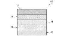
- the all-solid-state lithium-ion battery 100 includes a solid electrolyte layer 11, a positive electrode mixture layer 12, a negative electrode mixture layer 13, a positive electrode current collector 14, and a negative electrode current collector 15.
- the all-solid-state lithium-ion battery 100 includes the oxide solid electrolyte of the present disclosure. That is, the all-solid lithium-ion battery 100 contains the oxide solid electrolyte of the present disclosure in at least one of the solid electrolyte layer 11, the positive electrode active material layer 12, and the positive electrode active material layer 12.
- each part will be described.
- the solid electrolyte layer 11 is a layer formed between the positive electrode active material layer 12 and the negative electrode active material layer 13.
- the solid electrolyte layer 11 contains a solid electrolyte.
- a solid electrolyte other than the oxide solid electrolyte of the present disclosure may be used.
- the solid electrolyte other than the oxide solid electrolyte of the present disclosure include lithium aluminum titanium phosphorus oxide (LATP), lithium aluminum germanium phosphorus oxide (LAGP), lithium lanthanum zirconium oxide (LLZ) and the like.
- These solid electrolytes may be used alone or in admixture of two or more, or may be combined with the oxide solid electrolytes of the present disclosure.
- the thickness of the solid electrolyte layer 11 can be appropriately selected.
- the thickness of the solid electrolyte layer 11 is preferably 200 ⁇ m or less, for example.
- the lithium ion conductivity of the solid electrolyte other than the oxide solid electrolyte of the present disclosure is preferably 1.0 ⁇ 10 -5 S / cm or more, more preferably 1.0 ⁇ 10 -4 S / cm or more. be. Within this range, the battery characteristics of the all-solid-state lithium-ion battery 100 are further improved.
- the solid electrolyte layer 11 may further contain a binder.
- the binder is not particularly limited, but a thermoplastic resin, a thermosetting resin and the like can be used, and for example, polyethylene, polypropylene, polytetrafluoroethylene (PTFE), polyfluorovinylidene (PVDF), styrene butadiene rubber, tetra.
- the content of the binder in the solid electrolyte layer 11 of the present disclosure is preferably 0% by mass to 10% by mass. Within this range, the solid electrolyte and the like can be retained while maintaining the conductivity of the electrode mixture. A more preferable binder content is 0% by mass to 5% by mass.
- the positive electrode active material layer 12 is formed on the positive electrode current collector 14.
- the positive electrode active material layer 12 contains a solid electrolyte, an electrode active material, and a conductive material.
- the positive electrode active material layer 12 will be described.
- the thickness of the positive electrode active material layer 12 can be appropriately selected.
- the thickness of the positive electrode active material layer 12 is preferably 200 ⁇ m or less, for example.
- the oxide solid electrolyte of the present disclosure may be contained, or a solid electrolyte other than the oxide solid electrolyte of the present disclosure may be contained.
- the solid electrolyte other than the oxide solid electrolyte of the present disclosure include lithium aluminum titanium phosphorus oxide (LATP), lithium aluminum germanium phosphorus oxide (LAGP), lithium lanthanum zirconium oxide (LLZ) and the like.
- the solid electrolyte other than the above-mentioned oxide solid electrolyte of the present disclosure may be used alone or in combination of two or more, or may be combined with the oxide solid electrolyte of the present disclosure.
- the lithium ion conductivity of the solid electrolyte other than the oxide solid electrolyte of the present disclosure is preferably 1.0 ⁇ 10 -5 S / cm or more, more preferably 1.0 ⁇ 10 -4 S / cm or more. be. Within this range, the battery characteristics of the all-solid-state lithium-ion battery 100 are further improved.
- the electrode active material (positive electrode active material) used for the positive electrode is not particularly limited as long as it is a material capable of reversibly releasing and storing lithium ions and capable of electron transport.
- a positive electrode active material for example, lithium transition metal oxides such as lithium cobalt oxide, lithium nickel oxide, lithium manganese oxide, and lithium iron phosphorus oxide, and sulfur-based active materials such as sulfur and its discharge products, lithium sulfide and lithium polysulfide. And so on.
- the positive electrode active material may be composed of only one of the above materials, or may be composed of two or more of the above materials.
- the positive electrode conductive material a conductive auxiliary agent that can be generally used for a lithium ion secondary battery and an all-solid-state lithium ion secondary battery can be used.
- the positive electrode conductive material include carbon black such as acetylene black and kechen black; carbon fiber; vapor phase carbon fiber; graphite powder; carbon nanotube and carbon material such as activated charcoal.
- the conductive material may be composed of only one of the above materials, or may be composed of two or more of the above materials.
- the oxide solid electrolyte of the present disclosure is used when the total mass of the oxide solid electrolyte, the positive electrode active material, and the positive electrode conductive material is 100.
- the mass ratio of the positive electrode active material and the positive electrode conductive material is preferably 20 to 80:20 to 80: 0 to 30. If the mass ratio of the oxide solid electrolyte of the present disclosure, the positive electrode active material, and the positive electrode conductive material is in the above range, higher battery characteristics can be obtained.
- the content of the oxide solid electrolyte in the positive electrode active material layer 12 is preferably 20% by mass to 80% by mass. Further, the content of the positive electrode active material in the positive electrode active material layer 12 is preferably 20% by mass to 80% by mass.
- the content of the positive electrode conductive material in the positive electrode active material layer 12 is preferably 0% by mass to 30% by mass. The content of the positive electrode conductive material is more preferably 0% by mass to 25% by mass.
- the positive electrode active material layer 12 may further contain the binder used in the electrode mixture of the present disclosure.
- the negative electrode active material layer 13 is formed on the negative electrode current collector 15.
- the negative electrode active material layer 13 contains a solid electrolyte, a negative electrode active material, and a negative electrode conductive material.
- the negative electrode active material layer 13 will be described.
- the thickness of the negative electrode active material layer 13 can be appropriately selected.
- the thickness of the negative electrode active material layer 13 is preferably 200 ⁇ m or less, for example.
- the oxide solid electrolyte of the present disclosure may be contained, or a solid electrolyte other than the oxide solid electrolyte of the present disclosure may be contained.
- the solid electrolyte other than the oxide solid electrolyte of the present disclosure include lithium aluminum titanium phosphorus oxide (LATP), lithium aluminum germanium phosphorus oxide (LAGP), lithium lanthanum zirconium oxide (LLZ) and the like.
- the solid electrolyte other than the above-mentioned oxide solid electrolyte of the present disclosure may be used alone or in combination of two or more, or may be combined with the oxide solid electrolyte of the present disclosure.
- the lithium ion conductivity of the solid electrolyte other than the oxide solid electrolyte of the present disclosure is preferably 1.0 ⁇ 10 -5 S / cm or more, more preferably 1.0 ⁇ 10 -4 S / cm or more. be. Within this range, the battery characteristics of the all-solid-state lithium-ion battery 100 are further improved.
- the negative electrode active material is not particularly limited as long as it can reversibly release and occlude lithium ions and can transport electrons.
- the negative electrode active material include carbonaceous materials such as natural graphite, artificial graphite, resin charcoal, carbon fiber, activated charcoal, hard carbon, and soft carbon; tin, tin alloy, silicon, silicon alloy, gallium, gallium alloy, indium, etc. Alloy-based materials mainly composed of indium alloys, aluminum, aluminum alloys, etc .; conductive polymers such as polyacene, polyacetylene, polypyrrole, etc .; metallic lithium: lithium titanium composite oxide (for example, Li 4 Ti 5 O 12 ) and the like can be mentioned.
- the negative electrode active material may be composed of only one of the above materials, or may be composed of two or more of the above materials.
- the negative electrode conductive material a conductive auxiliary agent that can be generally used for a lithium ion secondary battery and an all-solid-state lithium ion secondary battery can be used.
- the positive electrode conductive material include carbon black such as acetylene black and kechen black; carbon fiber; vapor phase carbon fiber; graphite powder; carbon nanotube and carbon material such as activated charcoal.
- the conductive material may be composed of only one of the above materials, or may be composed of two or more of the above materials.
- the oxide solid electrolyte of the present disclosure is used when the total mass of the oxide solid electrolyte, the negative electrode active material, and the negative electrode conductive material is 100.
- the mass ratio of the negative electrode active material and the negative electrode conductive material is 20 to 80:20 to 80: 0 to 30. If the mass ratio of the oxide solid electrolyte of the present disclosure, the negative electrode active material, and the negative electrode conductive material is in the above range, higher battery characteristics can be obtained.
- the content of the oxide solid electrolyte in the negative electrode active material layer 13 is preferably 20% by mass to 80% by mass. Further, the content of the negative electrode active material in the negative electrode active material layer 13 is preferably 20% by mass to 80% by mass.
- the content of the negative electrode conductive material in the negative electrode active material layer 13 is preferably 0% by mass to 30% by mass. A more preferable content of the negative electrode conductive material is 0% by mass to 25% by mass.
- the negative electrode active material layer 13 may further contain the binder used in the electrode mixture of the present disclosure.
- the positive electrode current collector 14 is provided so as to be in contact with the positive electrode active material layer 12. The presence of the positive electrode current collector 14 facilitates the extraction of electricity from the positive electrode active material layer 12.
- a known positive electrode current collector can be used, and examples thereof include Al and SUS. Further, the thickness and shape of the positive electrode current collector 14 can be appropriately selected.
- the negative electrode current collector 15 is provided so as to be in contact with the negative electrode active material layer 13. The presence of the negative electrode current collector 15 facilitates the extraction of electricity from the negative electrode active material layer 13.
- a known negative electrode current collector can be used, and examples thereof include Cu. If the negative electrode active material layer 13 has high electron conductivity, the negative electrode current collector 15 may not be provided. Further, the thickness and shape of the negative electrode current collector 15 can be appropriately selected.
- the all-solid-state lithium-ion battery 100 can be manufactured by a known method.
- the positive electrode current collector 14 is provided, but if the electron conductivity of the positive electrode active material layer 12 is high, the positive electrode current collector 14 may not be provided.
- the negative electrode current collector 15 is provided, but if the negative electrode active material layer 13 has high electron conductivity, the negative electrode current collector 15 may not be provided.
- the conditions in the examples are one condition example adopted for confirming the feasibility and effect of the present invention, and the present invention is based on this one condition example. Not limited.
- the present invention can adopt various conditions as long as the gist of the present invention is not deviated and the object of the present invention is achieved.
- Example 1 Lithium sulfate (manufactured by Wako Pure Chemical Industries, Ltd.) and lithium carbonate (manufactured by Rare Metallic) were weighed at 543 mg of lithium sulfate and 157 mg of lithium carbonate so as to have a molar ratio of 70:30.
- Example 1 by using a planetary ball mill (Premium Line P-7 manufactured by Frilsch), weighing lithium sulfate and lithium carbonate are placed in an 80 ml pot together with about 120 g of 5 mm zirconia balls and mixed at a revolution speed of 370 rpm for 60 hours. Oxide solid electrolyte was obtained.
- Example 2 After weighing 828 mg of lithium sulfate and 372 mg of lithium carbonate so that the molar ratio of lithium sulfate and lithium carbonate is 60:40, they are mixed under the same conditions as in Example 1 to obtain the oxide solid electrolyte of Example 2. rice field.
- Example 3 Lithium sulfate and lithium carbonate were weighed at 359 mg of lithium sulfate and 241 mg of lithium carbonate so that the molar ratio was 50:50, and then mixed under the same conditions as in Example 1 to obtain the oxide solid electrolyte of Example 3. rice field.
- Example 4 After weighing 299 mg of lithium sulfate and 301 mg of lithium carbonate so that the molar ratio of lithium sulfate and lithium carbonate was 40:60, they were mixed under the same conditions as in Example 1 to obtain the oxide solid electrolyte of Example 4. ..
- Example 5 After weighing 273 mg of lithium sulfate and 427 mg of lithium carbonate so that the molar ratio of lithium sulfate and lithium carbonate was 30:70, they were mixed under the same conditions as in Example 1 to obtain the oxide solid electrolyte of Example 5. ..
- Example 6 Lithium sulfate, lithium carbonate, and lithium iodide (manufactured by Sigma Aldrich) were weighed with 717 mg of lithium sulfate, 321 mg of lithium carbonate, and 162 mg of lithium iodide so that the molar ratio was 54:36:10. Mixing was performed under the same conditions to obtain the oxide solid electrolyte of Example 6.
- Example 7 Lithium sulfate, lithium carbonate, and lithium iodide were weighed at 614 mg of lithium sulfate, 275 mg of lithium carbonate, and 311 mg of lithium iodide so as to have a molar ratio of 48:32:20, and then mixed under the same conditions as in Example 1. The oxide solid electrolyte of Example 7 was obtained.
- Example 8 Lithium sulfate, lithium carbonate, and lithium iodide were weighed at 518 mg of lithium sulfate, 232 mg of lithium carbonate, and 450 mg of lithium iodide so as to have a molar ratio of 42:28:30, and then mixed under the same conditions as in Example 1. The oxide solid electrolyte of Example 8 was obtained.
- Example 9 Lithium sulfate, lithium carbonate, and lithium iodide were weighed at 428 mg of lithium sulfate, 192 mg of lithium carbonate, and 280 mg of lithium iodide so as to have a molar ratio of 36:24:40, and then mixed under the same conditions as in Example 1. The oxide solid electrolyte of Example 9 was obtained.
- Example 10 Lithium sulfate, lithium carbonate, and lithium iodide were weighed at 345 mg of lithium sulfate, 155 mg of lithium carbonate, and 700 mg of lithium iodide so as to have a molar ratio of 30:20:50, and then mixed under the same conditions as in Example 1. The oxide solid electrolyte of Example 10 was obtained.
- Example 11 Lithium sulfate, lithium carbonate, and lithium chloride (manufactured by Sigma Aldrich) were weighed with 746 mg of lithium sulfate, 334 mg of lithium carbonate, and 120 mg of lithium chloride so as to have a molar ratio of 48:32:20, and then the same conditions as in Example 1. To obtain the oxide solid electrolyte of Example 11.
- Example 12 Lithium sulfate, lithium carbonate, and lithium chloride were weighed at 722 mg of lithium sulfate, 323 mg of lithium carbonate, and 155 mg of lithium chloride so as to have a molar ratio of 45:30:25, and then mixed under the same conditions as in Example 1 to Example. Twelve oxide solid electrolytes were obtained.
- Example 13 Lithium sulfate, lithium carbonate, and lithium chloride were weighed at 696 mg of lithium sulfate, 312 mg of lithium carbonate, and 192 mg of lithium chloride so as to have a molar ratio of 42:28:30, and then mixed under the same conditions as in Example 1 to Example. Thirteen oxide solid electrolytes were obtained.
- Example 14 Lithium sulfate, lithium carbonate, and lithium chloride were weighed at 639 mg of lithium sulfate, 287 mg of lithium carbonate, and 274 mg of lithium chloride so as to have a molar ratio of 36:24:40, and then mixed under the same conditions as in Example 1 to Example. 14 oxide solid electrolytes were obtained.
- Example 15 Lithium sulfate, lithium carbonate, and lithium bromide (manufactured by Sigma Aldrich) were weighed at 338 mg of lithium sulfate, 151 mg of lithium carbonate, and 111 mg of lithium bromide so as to have a molar ratio of 48:32:20, and then the same as in Example 1. The mixture was mixed under the conditions of (1) to obtain the oxide solid electrolyte of Example 15.
- Example 16 Lithium sulfate, lithium carbonate, and lithium bromide were weighed at 636 mg of lithium sulfate, 285 mg of lithium carbonate, and 279 mg of lithium bromide so as to have a molar ratio of 45:30:25, and then mixed under the same conditions as in Example 1. The oxide solid electrolyte of Example 16 was obtained.
- Example 17 Lithium sulfate, lithium carbonate, and lithium bromide were weighed at 596 mg of lithium sulfate, 267 mg of lithium carbonate, and 336 mg of lithium bromide so as to have a molar ratio of 42:28:30, and then mixed under the same conditions as in Example 1 to carry out. The oxide solid electrolyte of Example 17 was obtained.
- Example 18 Lithium sulfate, lithium carbonate, and lithium bromide were weighed at 258 mg of lithium sulfate, 116 mg of lithium carbonate, and 226 mg of lithium bromide so as to have a molar ratio of 36:24:40, and then mixed under the same conditions as in Example 1. The oxide solid electrolyte of Example 18 was obtained.
- Example 19 Lithium sulfate, lithium carbonate, and lithium phosphate (manufactured by Sigma Aldrich) were weighed at 530 mg of lithium sulfate, 237 mg of lithium carbonate, and 233 mg of lithium bromide so as to have a molar ratio of 48:32:20, and then the same as in Example 1. The mixture was mixed under the conditions of (1) to obtain the oxide solid electrolyte of Example 19.
- Example 20 Lithium sulfate, lithium carbonate, and lithium nitrate (manufactured by Sigma Aldrich) were weighed at 585 mg of lithium sulfate, 262 mg of lithium carbonate, and 153 mg of lithium bromide so as to have a molar ratio of 48:32:20, and then the same as in Example 1. The mixture was mixed under the conditions to obtain the oxide solid electrolyte of Example 20.
- Comparative Example 1 After weighing 1040 mg of lithium borate and 160 mg of lithium sulfate so that lithium borate (manufactured by Toyoshima Seisakusho Co., Ltd.) and lithium sulfate have a molar ratio of 90:10, they are mixed under the same conditions as in Example 1 and compared with Comparative Example 1. A solid electrolyte was obtained.
- Comparative Example 2 The solid electrolyte of Comparative Example 1 was heat-treated at 285 ° C. for 1 hour in an argon atmosphere to obtain the solid electrolyte of Comparative Example 2.
- Positive electrode mixture 1 As the positive electrode active material, 60 mg of lithium nickel cobalt manganese oxide (LiNi 1/3 Co 1/3 Mn 1/3 O 2 , manufactured by BASF Toda Battery Materials Co., Ltd.) and 40 mg of the oxide solid electrolyte of Example 2 were weighed and menowed. By mixing in a dairy pot, a powdery positive electrode mixture 1 was obtained.
- Powdery positive electrode mixture 2 was obtained by weighing and mixing in the same manner as in the positive electrode mixture 1 except that the oxide solid electrolyte of Example 13 was used instead of the oxide solid electrolyte of Example 2.
- Litive electrode mixture 3 As the positive electrode active material, 60 mg of lithium sulfide (manufactured by Mitsuwa Chemical Co., Ltd.), 120 mg of the oxide solid electrolyte of Example 13, and 20 mg of activated carbon (MSC-30) were weighed. Using a planetary ball mill (Premium Line P-7 manufactured by Frillsch), lithium sulfide weighed together with about 40 g of 5 mm zirconia balls, the oxide solid electrolyte of Example 13, and activated carbon were placed in a 45 ml pot, and the revolution speed was 370 rpm for 2 hours. By mixing, a powdery positive electrode mixture 3 was obtained.
- Electrode mixture 5 As the positive electrode active material, 60 mg of lithium sulfide, 60 mg of the oxide solid electrolyte of Example 13, and 20 mg of activated carbon (MSC-30) were weighed. Using a planetary ball mill (Premium Line P-7 manufactured by Frillsch), lithium sulfide weighed together with about 40 g of 5 mm zirconia balls, the oxide solid electrolyte of Example 13, and activated carbon were placed in a 45 ml pot, and the revolution speed was 370 rpm for 2 hours. Mixed. The obtained powder and the solid electrolyte of Example 13 were weighed so as to have a mass ratio of 70:30, and mixed in a mortar to obtain a powdery positive electrode mixture 5.
- a planetary ball mill Premium Line P-7 manufactured by Frillsch
- Comparative positive electrode mixture 1 A comparative positive electrode mixture 1 was obtained by weighing and mixing in the same manner as in the positive electrode mixture 1 except that the solid electrolyte of Comparative Example 2 was used instead of the oxide solid electrolyte of Example 2.
- Comparative positive electrode mixture 2 Lithium aluminum germanium phosphorus oxide (LAGP, manufactured by Toyoshima Seisakusho Co., Ltd.) was used as the oxide solid electrolyte in place of the solid electrolyte of Example 2, and the mixture was weighed and mixed in the same manner as in the positive electrode mixture 1 to form a powder. Comparative positive electrode mixture 2 was obtained.
- LAGP Lithium aluminum germanium phosphorus oxide
- Comparative positive electrode mixture 3 Lithium aluminum titanium phosphorus oxide (LATP, manufactured by Toyoshima Seisakusho Co., Ltd.) was used as the oxide solid electrolyte in place of the solid electrolyte of Example 2, and the mixture was weighed and mixed in the same manner as in the positive electrode mixture 1 to form a powder. Comparative positive electrode mixture 3 was obtained.
- Electrode mixture 1 Weigh 50 mg of lithium titanium oxide (Li 4 Ti 5 O 12 (LTO), manufactured by Ishihara Sangyo Co., Ltd.) and 50 mg of the oxide solid electrolyte of Example 2 as the negative electrode active material, and mix them in a Menou dairy pot to form a powdered negative electrode. Combined material 1 was obtained.
- Li 4 Ti 5 O 12 Li 4 Ti 5 O 12
- the powdery negative electrode mixture 2 was obtained by mixing in a Menou dairy pot under the same conditions as the negative electrode mixture 1 except that 50 mg of the oxide solid electrolyte of Example 8 was weighed instead of the oxide solid electrolyte of Example 2. Obtained.
- Negative electrode mixture 4 As the negative electrode active material, 50 mg of silicon (manufactured by Nikola Co., Ltd.) and 50 mg of the oxide solid electrolyte of Example 13 were weighed and mixed in an agate mortar to obtain a powdery negative electrode mixture 4.
- Nitative electrode mixture 5 A powdery negative electrode mixture 5 was obtained by weighing and mixing in the same manner as the positive electrode mixture 3 except that silicon was used as the negative electrode active material instead of lithium sulfide as the positive electrode active material.
- Nitative electrode mixture 6 A powdery negative electrode mixture 6 was obtained by weighing and mixing in the same manner as the positive electrode mixture 5 except that silicon was used as the negative electrode active material instead of lithium sulfide as the positive electrode active material.
- the composite product 1 and 80Li 2 S-20P 2 S 5 in which the solid electrolyte (E) (5Li 2 S-GeS 2 -P 2 S 5 ) was fired at 510 ° C. for 8 hours from the upper side of the ceramic cylindrical tube jig. was mixed with a ball mill at 500 rpm for 10 hours at a mass ratio of 90:10, and 80 mg of the mixed composite was added.
- a cylindrical jig (positive electrode current collector) made of SKD11 was inserted and pressed at a pressure of 720 MPa for 3 minutes to form a positive electrode layer having a diameter of 10 mm ⁇ and a thickness of about 0.1 mm.
- the SKD11 cylindrical jig (negative electrode current collector) inserted from the bottom was pulled out, and a 0.20 mm thick lithium sheet (manufactured by Honjo Metal Co., Ltd.) was punched to a diameter of 8 mm ⁇ with a punch.
- an impedance measuring device (Solartron Impedance Analyzer A1260) was used to measure the applied voltage at an applied voltage of 100 mV and a measurement frequency of 1 Hz to 32 MHz. The rate was calculated. Table 1 summarizes the conductivity and relative density of each solid electrolyte.
- Examples 1 to 20 oxide solid electrolytes contain Li 2 SO 4 and Li 2 CO 3 , and the molar ratio of Li 2 SO 4 to Li 2 CO 3 is 20: 80 to 80 :. Since it was 20 and had an exothermic peak of 200 ° C. or lower in the DSC curve, the relative density of the pellets obtained by pressing at room temperature and 1 GPa was 95% or more. Further, the solid electrolytes of Examples 1 to 20 had a conductivity of 1.0 ⁇ 10 -7 S / cm or more.
- the solid electrolytes of Comparative Examples 1 and 2 did not have an exothermic peak of 200 ° C. or lower in the DSC curve. Therefore, the relative density of the pellets obtained by pressing at room temperature and 1 GPa was less than 95%, and the deformability at room temperature was inferior.
- the positive electrode mixture 1 to 6 using the oxide solid electrolyte of the examples had excellent battery characteristics as compared with the comparative positive electrode mixture 1 to 3.
- the negative electrode mixture and the full cell using the oxide solid electrolyte of the example also had excellent battery characteristics.
- the oxide solid electrolyte of the present disclosure As the positive electrode, the negative electrode, and the solid electrolyte layer of the all-solid lithium ion battery, the positive electrode, the negative electrode, the solid electrolyte layer, and the full cell, which show good battery characteristics, can be pressed only at room temperature. Can be produced with. Since electrodes and full cells can be formed by a very simple method, the oxide solid electrolyte of the present invention and the electrode mixture using the same are suitable materials for mass production, and therefore have high industrial applicability.
Landscapes
- Chemical & Material Sciences (AREA)
- Engineering & Computer Science (AREA)
- Electrochemistry (AREA)
- General Chemical & Material Sciences (AREA)
- Organic Chemistry (AREA)
- Chemical Kinetics & Catalysis (AREA)
- Inorganic Chemistry (AREA)
- Materials Engineering (AREA)
- Manufacturing & Machinery (AREA)
- Physics & Mathematics (AREA)
- Condensed Matter Physics & Semiconductors (AREA)
- General Physics & Mathematics (AREA)
- Secondary Cells (AREA)
- Conductive Materials (AREA)
- Battery Electrode And Active Subsutance (AREA)
Abstract
この酸化物固体電解質は、硫酸リチウム(Li2SO4)と炭酸リチウム(Li2CO3)とを含む複合物であって、前記硫酸リチウムと前記炭酸リチウムとのモル比(Li2SO4:Li2CO3)が20:80~80:20であり、示差走査熱量測定で得られる曲線において、発熱ピークの位置が200℃以下であり、導電率が1.0×10⁻⁷S/cm以上である。
Description
本発明は、酸化物固体電解質、電極合材、および全固体リチウムイオン電池に関する。本願は、2021年1月8日に、日本に出願された特願2021-002328号に基づき優先権を主張し、その内容をここに援用する。
リチウムイオン2次電池は、エネルギー密度が高く、パソコン、携帯電話などの情報関連機器等に使用されている。近年、電気自動車またはハイブリッド自動車向けに高出力かつ高容量のリチウムイオン2次電池の開発が進められている。
しかし、現在のリチウムイオン2次電池は、可燃性の有機電解液を用いているので、リチウムイオン2次電池が異常発熱した際に発火しやすいという問題がある。実際、携帯機器でリチウムイオン2次電池を原因とする発火事故が起こっており、安全性の改善が強く求められている。
リチウムイオン2次電池の安全性を改善する技術としては、固体電解質を用いる技術がある。しかし、固体電解質を用いた全固体リチウムイオン2次電池の場合、負極合材層、固体電解質層、及び正極合材層がそれぞれ固体―固体接触となる。そのため、有機電解液を使用する従来のリチウムイオン2次電池と比較して、電子およびイオンの移動経路は著しく少なくなる。特に、導電率の高い酸化物固体電解質は、硬い粒子であり変形しにくいので、プレスなどをしても固体-固体間の良好な接触状態を得ることができない。そのため、導電率が高い酸化物固体電解質では、酸化物固体電解質間の電子またはイオンの伝導性が低い。よって、現在、固体電解質間の接触状態を改善することが求められている。
固体電解質間の接触状態を改善する技術としては、特許文献1には、酸化物基準の質量%で、ZrO2成分を2.6~52.0%含有するリチウムイオン伝導性無機物質を焼結する技術が開示されている。非特許文献1には、NASICON型の結晶構造を持つガラスセラミックスを焼結する技術が開示されている。非特許文献2には、Li3BO3-Li2SO4を熱プレスする技術が開示されている。
T. Kato, et al.,Effects of sintering temperature on interfacial structure and interfacial resistance for all-solid-state rechargeable lithium batteries. J. Power Source 325(2016)584-590
K. Nagao,et al., Highly Stable Li/Li3BO3-Li2SO4 Interface and Application to Bulk-Type All-Solid-State Lithium Metal Batteries. Appl. Energy Mater. 2(2019) 3042-3048
特許文献1および非特許文献1の場合、高温で焼結させて粒子間の接触を改善しているが、固体電解質および電極活物質の高温での反応により、イオン電導性および充放電反応性が低下するという問題がある。加えて、特許文献1および非特許文献1の場合、高温での処理が必要となるので、設備費用およびランニングコストが高くなるという問題がある。また、非特許文献2の技術では、常温では良好な粒子間接触状態が形成できていない材料を熱プレスすることで、粒子間の接触状態を改善しているが、高温を必要とするため、設備費用およびランニングコストが高くなるという問題がある。そのため、非特許文献2に開示された固体電解質よりも常温において、より高い変形性を有する固体電解質が求められている。
本発明は、上記の課題を鑑みてなされた発明であり、常温での良好な変形性を有し、かつ、導電率が高い酸化物固体電解質を提供することを主目的とする。ここで、常温とは20℃~30℃をいう。また、「常温での良好な変形性」とは、例えば、常温、1GPaのプレスにおいて相対密度が95%以上となる変形性をいう。
前記課題を解決するために、本発明は以下の手段を提案している。
(1)本発明の一態様に係る酸化物固体電解質は、硫酸リチウム(Li2SO4)と炭酸リチウム(Li2CO3)とを含む複合物であって、
前記硫酸リチウムと前記炭酸リチウムとのモル比(Li2SO4:Li2CO3)が20:80~80:20であり、
示差走査熱量測定で得られる曲線において、発熱ピークの位置が200℃以下であり、 導電率が1.0×10⁻⁷S/cm以上である。
(2)上記(1)に記載の酸化物固体電解質は、塩化リチウム、臭化リチウム、ヨウ化リチウム、ホウ酸リチウム、リン酸リチウム、硝酸リチウム、ケイ酸リチウム、およびアルミン酸リチウムからなる群より選択される少なくとも1種をさらに含んでもよい。
(3)本発明の一態様に係る電極合材は、
上記(1)または(2)に記載の酸化物固体電解質と、
電極活物質と、
導電材と、
を含み、
前記酸化物固体電解質と、前記電極活物質と、前記導電材と、の質量比(酸化物固体電解質:電極活物質:導電材)が20~80:20~80:0~30である。
(4)本発明の一態様に係る全固体リチウムイオン電池は、上記(1)または(2)に記載の酸化物固体電解質を含む。
(5)上記(4)に記載の全固体リチウムイオン電池は、前記酸化物固体電解質を含む固体電解質層を備えてもよい。
(6)上記(4)または(5)に記載の全固体リチウムイオン電池は、前記酸化物固体電解質を含む正極活物質層または前記酸化物固体電解質を含む負極活物質層を備えてもよい。
(7)上記(6)に記載の全固体リチウムイオン電池は、前記正極活物質層が、前記酸化物固体電解質、正極活物質および正極導電材を含み、
前記酸化物固体電解質と、前記正極活物質と、前記正極導電材と、の質量比(酸化物固体電解質:正極活物質:正極導電材)が20~80:20~80:0~30であってもよい。
(8)上記(6)または(7)に記載の全固体リチウムイオン電池は、前記負極活物質層が、前記酸化物固体電解質、負極活物質および負極導電材を含み、
前記酸化物固体電解質と、前記負極活物質と、前記負極導電材と、の質量比(酸化物固体電解質:負極活物質:負極導電材)が20~80:20~80:0~30であってもよい。
(1)本発明の一態様に係る酸化物固体電解質は、硫酸リチウム(Li2SO4)と炭酸リチウム(Li2CO3)とを含む複合物であって、
前記硫酸リチウムと前記炭酸リチウムとのモル比(Li2SO4:Li2CO3)が20:80~80:20であり、
示差走査熱量測定で得られる曲線において、発熱ピークの位置が200℃以下であり、 導電率が1.0×10⁻⁷S/cm以上である。
(2)上記(1)に記載の酸化物固体電解質は、塩化リチウム、臭化リチウム、ヨウ化リチウム、ホウ酸リチウム、リン酸リチウム、硝酸リチウム、ケイ酸リチウム、およびアルミン酸リチウムからなる群より選択される少なくとも1種をさらに含んでもよい。
(3)本発明の一態様に係る電極合材は、
上記(1)または(2)に記載の酸化物固体電解質と、
電極活物質と、
導電材と、
を含み、
前記酸化物固体電解質と、前記電極活物質と、前記導電材と、の質量比(酸化物固体電解質:電極活物質:導電材)が20~80:20~80:0~30である。
(4)本発明の一態様に係る全固体リチウムイオン電池は、上記(1)または(2)に記載の酸化物固体電解質を含む。
(5)上記(4)に記載の全固体リチウムイオン電池は、前記酸化物固体電解質を含む固体電解質層を備えてもよい。
(6)上記(4)または(5)に記載の全固体リチウムイオン電池は、前記酸化物固体電解質を含む正極活物質層または前記酸化物固体電解質を含む負極活物質層を備えてもよい。
(7)上記(6)に記載の全固体リチウムイオン電池は、前記正極活物質層が、前記酸化物固体電解質、正極活物質および正極導電材を含み、
前記酸化物固体電解質と、前記正極活物質と、前記正極導電材と、の質量比(酸化物固体電解質:正極活物質:正極導電材)が20~80:20~80:0~30であってもよい。
(8)上記(6)または(7)に記載の全固体リチウムイオン電池は、前記負極活物質層が、前記酸化物固体電解質、負極活物質および負極導電材を含み、
前記酸化物固体電解質と、前記負極活物質と、前記負極導電材と、の質量比(酸化物固体電解質:負極活物質:負極導電材)が20~80:20~80:0~30であってもよい。
本開示の上記態様によれば、常温での良好な変形性を有し、かつ、導電率が高い酸化物固体電解質、電極合材および全固体リチウムイオン電池を提供することができる。
<酸化物固体電解質>
本開示の酸化物固体電解質について、説明する。なお、以下に例示する実施形態は、本発明の理解を容易にするためのものであり、本発明を限定して解釈するためのものではない。本発明は、その趣旨を逸脱することなく、以下の実施形態から変更、改良することができる。
本開示の酸化物固体電解質について、説明する。なお、以下に例示する実施形態は、本発明の理解を容易にするためのものであり、本発明を限定して解釈するためのものではない。本発明は、その趣旨を逸脱することなく、以下の実施形態から変更、改良することができる。
(硫酸リチウム(Li2SO4)と炭酸リチウム(Li2CO3)とを含む複合物)
本開示の酸化物固体電解質は、硫酸リチウム(Li2SO4)と、炭酸リチウム(Li2CO3)とを含む複合物である。ここで、複合物とは、硫酸リチウムと炭酸リチウムとを含む原料を、例えば、遊星ボールミルで混合し、複合化したものをいう。本開示の酸化物固体電解質は、硫酸リチウムと炭酸リチウムとを含むことで、良好な導電率および良好な変形性が得られる。
本開示の酸化物固体電解質は、硫酸リチウム(Li2SO4)と、炭酸リチウム(Li2CO3)とを含む複合物である。ここで、複合物とは、硫酸リチウムと炭酸リチウムとを含む原料を、例えば、遊星ボールミルで混合し、複合化したものをいう。本開示の酸化物固体電解質は、硫酸リチウムと炭酸リチウムとを含むことで、良好な導電率および良好な変形性が得られる。
(硫酸リチウムと前記炭酸リチウムとのモル比(Li2SO4:Li2CO3)が20:80~80:20)
本開示の酸化物固体電解質は、硫酸リチウム(Li2SO4)と炭酸リチウム(Li2CO3)とを含み、硫酸リチウムと炭酸リチウムとのモル比(Li2SO4:Li2CO3)が20:80~80:20である。硫酸リチウムと炭酸リチウムとのモル比が上記の範囲であれば、酸化物固体電解質は、常温での良好な変形性を有する。より好ましい硫酸リチウムと炭酸リチウムとのモル比は、30:70~70:30である。
本開示の酸化物固体電解質は、硫酸リチウム(Li2SO4)と炭酸リチウム(Li2CO3)とを含み、硫酸リチウムと炭酸リチウムとのモル比(Li2SO4:Li2CO3)が20:80~80:20である。硫酸リチウムと炭酸リチウムとのモル比が上記の範囲であれば、酸化物固体電解質は、常温での良好な変形性を有する。より好ましい硫酸リチウムと炭酸リチウムとのモル比は、30:70~70:30である。
本開示の酸化物固体電解質において、硫酸リチウムおよび炭酸リチウムの合計含有量が、30質量%~100質量%であることが好ましい。硫酸リチウムおよび炭酸リチウムの合計含有量が上記の範囲であれば、常温でのより良好な変形性を得ることができるので好ましい。より好ましい硫酸リチウムおよび炭酸リチウムの合計含有量は、40質量%~100質量%である。
(塩化リチウム、臭化リチウム、ヨウ化リチウム、ホウ酸リチウム、リン酸リチウム、硝酸リチウム、ケイ酸リチウム、およびアルミン酸リチウムからなる群より選択される少なくとも1種)
本開示の酸化物固体電解質は、塩化リチウム、臭化リチウム、ヨウ化リチウム、ホウ酸リチウム、リン酸リチウム、硝酸リチウム、ケイ酸リチウム、およびアルミン酸リチウムからなる群より選択される少なくとも1種をさらに含むことが好ましい。塩化リチウム、臭化リチウム、ヨウ化リチウム、ホウ酸リチウム、リン酸リチウム、硝酸リチウム、ケイ酸リチウム、およびアルミン酸リチウムからなる群より選択される少なくとも1種をさらに含むことで、より高い導電率を得ることができるので好ましい。
本開示の酸化物固体電解質は、塩化リチウム、臭化リチウム、ヨウ化リチウム、ホウ酸リチウム、リン酸リチウム、硝酸リチウム、ケイ酸リチウム、およびアルミン酸リチウムからなる群より選択される少なくとも1種をさらに含むことが好ましい。塩化リチウム、臭化リチウム、ヨウ化リチウム、ホウ酸リチウム、リン酸リチウム、硝酸リチウム、ケイ酸リチウム、およびアルミン酸リチウムからなる群より選択される少なくとも1種をさらに含むことで、より高い導電率を得ることができるので好ましい。
本開示の酸化物固体電解質における塩化リチウム、臭化リチウム、ヨウ化リチウム、ホウ酸リチウム、リン酸リチウム、硝酸リチウム、ケイ酸リチウム、およびアルミン酸リチウムの合計含有量は、0質量%~70質量%であることが好ましい。塩化リチウム、臭化リチウム、ヨウ化リチウム、ホウ酸リチウム、リン酸リチウム、硝酸リチウム、ケイ酸リチウム、およびアルミン酸リチウムの合計含有量が上記の範囲であれば、より良好な導電率を得ることができるので好ましい。より好ましい塩化リチウム、臭化リチウム、ヨウ化リチウム、ホウ酸リチウム、リン酸リチウム、硝酸リチウム、ケイ酸リチウム、およびアルミン酸リチウムの合計含有量は、0質量%~60質量%である。
本開示の酸化物固体電解質の化学組成は、例えば、リチウムイオン2次電池の正極、固体電解質層、または負極の断面において、電解放出型透過電子顕微鏡(TEM)に搭載されたエネルギー分散型X線分光装置(EDX)とラマン分光法にて定量することができる。
(示差走査熱量測定で得られる曲線において、発熱ピークの位置が200℃以下)
本開示の酸化物固体電解質は、示差走査熱量測定(DSC)測定において得られる曲線(DSC曲線)において、200℃以下の発熱ピークを有する。DSC曲線において、発熱ピークの位置が200℃以下であることで、酸化物固体電解質の良好な変形性が得られる。より好ましい発熱ピークの位置は、190℃以下である。発熱ピークの位置の下限は特に限定されないが、例えば、80℃以上としてもよい。なお、DSC曲線上に複数の発熱ピークがある場合は、最も発熱量の大きいピークの位置を発熱ピーク位置とする。
本開示の酸化物固体電解質は、示差走査熱量測定(DSC)測定において得られる曲線(DSC曲線)において、200℃以下の発熱ピークを有する。DSC曲線において、発熱ピークの位置が200℃以下であることで、酸化物固体電解質の良好な変形性が得られる。より好ましい発熱ピークの位置は、190℃以下である。発熱ピークの位置の下限は特に限定されないが、例えば、80℃以上としてもよい。なお、DSC曲線上に複数の発熱ピークがある場合は、最も発熱量の大きいピークの位置を発熱ピーク位置とする。
本開示の酸化物固体電解質は、DSC曲線において得られる200℃以下の発熱ピークの発熱量が5J/g以上であることが好ましい。DSC曲線において得られる200℃以下の発熱ピークの発熱量が上記の範囲であれば、より高い変形性が得られるので好ましい。より好ましい発熱量は、10J/g以上である。さらに好ましい発熱量は15J/g以上である。発熱ピークの発熱量の上限は特に限定されてないが、例えば、500J/g以下としてもよい。
本開示の酸化物固体電解質の発熱ピークは、例えば、以下の方法で測定することができる。不活性ガス(例えばAr)で満たされたグローブボックス中で酸化物固体電解質(約10mg)をAl密閉試料容器(日立ハイテクサイエンス社製 GCA-0017)に入れ、密閉する。密閉後の容器を示差走査熱量計(例えば、セイコーインスツルメンツ社製DSC6200)に設置し、温度範囲50℃~300℃、昇温速度10℃/分で測定を行うことで、酸化物固体電解質のDSC曲線を得ることができる。得られたDSC曲線から酸化物固体電解質の発熱ピークの位置と発熱量が得られる。ピーク位置および発熱量は例えば、示差走査熱量計DSC6200に付属するソフトウェアを用いて計算することができる。
(導電率が1.0×10⁻⁷S/cm以上)
本開示の酸化物固体電解質の導電率は、1.0×10⁻⁷S/cm以上である。酸化物固体電解質の導電率が1.0×10-7S/cm未満の場合、全固体リチウムイオン電池の特性が低下する場合がある。より好ましい酸化物固体電解質の導電率は2.0×10-7S/cm以上である。さらに好ましい酸化物固体電解質の導電率は、4.0×10-7S/cm以上である。
本開示の酸化物固体電解質の導電率は、1.0×10⁻⁷S/cm以上である。酸化物固体電解質の導電率が1.0×10-7S/cm未満の場合、全固体リチウムイオン電池の特性が低下する場合がある。より好ましい酸化物固体電解質の導電率は2.0×10-7S/cm以上である。さらに好ましい酸化物固体電解質の導電率は、4.0×10-7S/cm以上である。
本開示の酸化物固体電解質の導電率は、例えば、以下の方法で測定することができる。 アルゴンガス雰囲気グローブボックス内にて、直径10mmの錠剤成形器(例えば、日本分光製)に直径10mmに打ち抜いたAl箔またはAu箔を入れ、その上から固体電解質粉末を入れ、均したのちにさらに直径10mmに打ち抜いたAl箔またはAu箔を入れ、常温で1GPa、30分間プレスすることで固体電解質測定用のペレットを得る。得られたペレットをフラットセル内に配置し、密閉することで導電率測定用セルとし、常温にて、インピーダンス測定装置(例えば、ソーラトロン社インピーダンスアナライザーA1260)にて印加電圧50mV、測定周波数1Hz~32MHzにて測定し、得られたナイキストプロットの半円弧の低周波端の抵抗値から導電率を算出することができる。
(相対密度95%以上)
本開示の酸化物固体電解質は、常温での変形性に優れる。例えば、本開示の酸化物固体電解質を常温で1GPaでプレスした場合、下記の式(1)で表される相対密度が95%以上となる。より好ましくは、常温で1GPaでプレスした場合における相対密度が98%以上である。さらに好ましくは、常温で1GPaでプレスした場合における相対密度が99%以上である。
本開示の酸化物固体電解質は、常温での変形性に優れる。例えば、本開示の酸化物固体電解質を常温で1GPaでプレスした場合、下記の式(1)で表される相対密度が95%以上となる。より好ましくは、常温で1GPaでプレスした場合における相対密度が98%以上である。さらに好ましくは、常温で1GPaでプレスした場合における相対密度が99%以上である。

本開示の酸化物固体電解質の相対密度は、以下の方法で測定することができる。アルゴンガス雰囲気グローブボックス内にて、直径10mmの錠剤成形器(例えば、日本分光製)に直径10mmに打ち抜いたAl箔またはAu箔を入れ、その上から固体電解質粉末を入れ、均した後にさらに直径10mmに打ち抜いたAl箔またはAu箔を入れ、常温で1GPa、30分間プレスすることで相対密度測定用のペレットを得る。得られたペレットの密度を上記(1)式のように、各原料の密度(g/cm3)および質量(g)から計算される理論密度で除することで算出することができる。
本開示の酸化物固体電解質の形状は特に限定されないが、例えば、粒状が好ましい。
(酸化物固体電解質の製造方法)
本開示の酸化物固体電解質の製造方法は、特に限定されないが、例えば、固相合成法、乾式メカニカルミリング処理、湿式メカニカルミリング処理、溶融急冷法、ゾル・ゲル法等があげられる。本開示の酸化物固体電解質の製造方法としては、特に乾式メカニカルミリング処理が好ましい。例えば、酸化物固体電解質の原料をジルコニアボールとともに370rpmで60時間混合することで本開示の酸化物固体電解質が得られる。製造条件については、得られた酸化物固体電解質のDSC測定を行い、発熱ピークの位置および発熱量を確認することで、適宜調整することができる。
本開示の酸化物固体電解質の製造方法は、特に限定されないが、例えば、固相合成法、乾式メカニカルミリング処理、湿式メカニカルミリング処理、溶融急冷法、ゾル・ゲル法等があげられる。本開示の酸化物固体電解質の製造方法としては、特に乾式メカニカルミリング処理が好ましい。例えば、酸化物固体電解質の原料をジルコニアボールとともに370rpmで60時間混合することで本開示の酸化物固体電解質が得られる。製造条件については、得られた酸化物固体電解質のDSC測定を行い、発熱ピークの位置および発熱量を確認することで、適宜調整することができる。
<電極合材>
本開示の電極合材は、本開示の酸化物固体電解質、電極活物質および導電材を含む。電極合材について、以下、説明する。
本開示の電極合材は、本開示の酸化物固体電解質、電極活物質および導電材を含む。電極合材について、以下、説明する。
(活物質)
電極活物質は、リチウムイオン2次電池で使用されるものであれば特に限定されない。正極に用いる電極活物質(正極活物質)としては、リチウムイオンを可逆的に放出・吸蔵でき、電子輸送が行える材料であれば特に限定されない。正極活物質としては。例えば、リチウムコバルト酸化物、リチウムニッケル酸化物、リチウムマンガン酸化物、リチウム鉄リン酸化物などのリチウム遷移金属酸化物、硫黄及びその放電生成物である硫化リチウム、多硫化リチウム等の硫黄系活物質等が挙げられる。正極活物質は、上記材料の1種単独で構成されてもよいし、2種以上で構成されてもよい。
電極活物質は、リチウムイオン2次電池で使用されるものであれば特に限定されない。正極に用いる電極活物質(正極活物質)としては、リチウムイオンを可逆的に放出・吸蔵でき、電子輸送が行える材料であれば特に限定されない。正極活物質としては。例えば、リチウムコバルト酸化物、リチウムニッケル酸化物、リチウムマンガン酸化物、リチウム鉄リン酸化物などのリチウム遷移金属酸化物、硫黄及びその放電生成物である硫化リチウム、多硫化リチウム等の硫黄系活物質等が挙げられる。正極活物質は、上記材料の1種単独で構成されてもよいし、2種以上で構成されてもよい。
負極に用いる電極活物質(負極活物質)としては、リチウムイオンを可逆に放出・吸蔵でき、電子輸送が行える材料であれば特に限定されない。負極活物質としては、例えば、天然黒鉛、人造黒鉛、樹脂炭、炭素繊維、活性炭、ハードカーボン、ソフトカーボン等の炭素質材料;スズ、スズ合金、シリコン、シリコン合金、ガリウム、ガリウム合金、インジウム、インジウム合金、アルミニウム、アルミニウム合金等を主体とした合金系材料;ポリアセン、ポリアセチレン、ポリピロール等の導電性ポリマー;金属リチウム:リチウムチタン複合酸化物(例えばLi4Ti5O12)等が挙げられる。負極活物質は、上記材料の1種単独で構成されてもよいし、2種以上で構成されてもよい。
(導電材)
導電材は一般的にリチウムイオン2次電池及び全固体型リチウムイオン2次電池に使用可能な導電助剤を用いることができる。正極に用いられる導電材(正極導電材)としては、例えば、アセチレンブラック、ケチェンブラック等のカーボンブラック;カーボンファイバー;気相法炭素繊維;黒鉛粉末;カーボンナノチューブ、活性炭等の炭素材料、を挙げることができる。導電材は、上記材料の1種単独で構成されてもよいし、2種以上で構成されてもよい。
導電材は一般的にリチウムイオン2次電池及び全固体型リチウムイオン2次電池に使用可能な導電助剤を用いることができる。正極に用いられる導電材(正極導電材)としては、例えば、アセチレンブラック、ケチェンブラック等のカーボンブラック;カーボンファイバー;気相法炭素繊維;黒鉛粉末;カーボンナノチューブ、活性炭等の炭素材料、を挙げることができる。導電材は、上記材料の1種単独で構成されてもよいし、2種以上で構成されてもよい。
負極に用いられる導電材(負極導電材)としては、例えば、アセチレンブラック、ケチェンブラック等のカーボンブラック;カーボンファイバー;気相法炭素繊維;黒鉛粉末;カーボンナノチューブ、活性炭等の炭素材料、を挙げることができる。導電材は、上記材料の1種単独で構成されてもよいし、2種以上で構成されてもよい。
本開示の酸化物固体電解質、電極活物質および導電材の質量合計を100としたときに、本開示の酸化物固体電解質と、電極活物質と、導電材と、の質量比(酸化物固体電解質:電極活物質:導電材)は、20~80:20~80:0~30である。本開示の酸化物固体電解質と、電極活物質と、導電材と、の質量比が、上記の範囲であれば、高い電池特性が得られる。なお、正極に本開示の酸化物固体電解質を用いる場合(正極合材)は、酸化物固体電解質:正極活物質:正極導電材の質量比は、20~80:20~80:0~30である。負極に本開示の酸化物固体電解質を用いる場合(負極合材)は、酸化物固体電解質:負極活物質:負極導電材の質量比は、20~80:20~80:0~30である。
本開示の電極合材中の酸化物固体電解質の含有量は、20質量%~80質量%が好ましい。また、本開示の電極合材中の電極活物質の含有量は、20質量%~80質量%であることが好ましい。本開示の電極合材中の導電材の含有量は0質量%~30質量%であることが好ましい。より好ましい導電材の含有量は0質量%~25質量%である。本開示の電極合材中の酸化物固体電解質、電極活物質、および導電材の各含有量が上記の範囲であれば、良好な電池特性が得られる。なお、酸化物固体電解質、電極活物質、導電材およびその他の成分の合計で100質量%とする。その他の成分としては、バインダーなどが挙げられる。
本開示の電極合材は、バインダーをさらに含有してもよい。バインダーとしては、特に限定されないが、熱可塑性樹脂や熱硬化性樹脂等を用いることができ、例えば、ポリエチレン、ポリプロピレン、ポリテトラフルオロエチレン(PTFE)、ポリフッ化ビニリデン(PVDF)、スチレンブタジエンゴム、テトラフルオロエチレン-ヘキサフルオロエチレン共重合体、テトラフルオロエチレン-ヘキサフルオロプロピレン共重合体(FEP)、テトラフルオロエチレン-パーフルオロアルキルビニルエーテル共重合体(PFA)、フッ化ビニリデン-ヘキサフルオロプロピレン共重合体、フッ化ビニリデン-クロロトリフルオロエチレン共重合体、エチレン-テトラフルオロエチレン共重合体(ETFE樹脂)、ポリクロロトリフルオロエチレン(PCTFE)、フッ化ビニリデン-ペンタフルオロプロピレン共重合体、プロピレン-テトラフルオロエチレン共重合体、エチレン-クロロトリフルオロエチレン共重合体(ECTFE)、フッ化ビニリデン-ヘキサフルオロプロピレン-テトラフルオロエチレン共重合体、フッ化ビニリデン-パーフルオロメチルビニルエーテル-テトラフルオロエチレン共重合体、エチレン-アクリル酸共重合体、ポリアクリル酸、ポリアクリル酸ナトリウム、ポリアクリル酸リチウム、ポリメタクリル酸、ポリメタクリル酸ナトリウム、ポリメタクリル酸リチウム等が挙げられる。これらのバインダーは、単独で使用しても良いし、2種以上を併用してもよい。
本開示の電極合材におけるバインダーの含有量は0質量%~10質量%であることが好ましい。この範囲であれば、電極合材の導電性を維持しつつ、活物質などを保持できる。より好ましいバインダーの含有量は、0質量%~5質量%である。
電極合材中の各成分比は、例えば、リチウムイオン2次電池の正極または負極の断面において、電解放出型透過電子顕微鏡(TEM)に搭載されたエネルギー分散型X線分光装置(EDX)とラマン分光法及び燃焼分解法にて定量することができる。
(電極合材の製造方法)
本開示の電極合材の製造方法は、酸化物固体電解質、電極活物質および導電材が均一に混合されていれば、特に限定されない。本開示の電極合材の製造方法としては、例えば、乾式メカニカルミリング処理、湿式メカニカルミリング処理、溶融急冷法などが挙げられる。
本開示の電極合材の製造方法は、酸化物固体電解質、電極活物質および導電材が均一に混合されていれば、特に限定されない。本開示の電極合材の製造方法としては、例えば、乾式メカニカルミリング処理、湿式メカニカルミリング処理、溶融急冷法などが挙げられる。
<全固体リチウムイオン電池>
次に、図1を参照し、本開示の一実施形態に係る全固体リチウムイオン電池100を説明する。全固体リチウムイオン電池100は、固体電解質層11、正極合材層12、負極合材層13、正極集電体14、負極集電体15を備える。全固体リチウムイオン電池100は、本開示の酸化物固体電解質を含む。即ち、全固体リチウムイオン電池100は、固体電解質層11、正極活物質層12、および正極活物質層12の少なくともいずれか1つの層に本開示の酸化物固体電解質を含む。以下、各部について説明する。
次に、図1を参照し、本開示の一実施形態に係る全固体リチウムイオン電池100を説明する。全固体リチウムイオン電池100は、固体電解質層11、正極合材層12、負極合材層13、正極集電体14、負極集電体15を備える。全固体リチウムイオン電池100は、本開示の酸化物固体電解質を含む。即ち、全固体リチウムイオン電池100は、固体電解質層11、正極活物質層12、および正極活物質層12の少なくともいずれか1つの層に本開示の酸化物固体電解質を含む。以下、各部について説明する。
(固体電解質層)
固体電解質層11は、正極活物質層12と負極活物質層13との間に形成される層である。固体電解質層11は、固体電解質を含有する。固体電解質層11に含有される固体電解質としては、本開示の酸化物固体電解質以外の固体電解質を用いてもよい。本開示の酸化物固体電解質以外の固体電解質としては、例えば、リチウムアルミニウムチタンリン酸化物(LATP)、リチウムアルミニウムゲルマニウムリン酸化物(LAGP)、リチウムランタンジルコニウム酸化物(LLZ)などが挙げられる。これらの固体電解質は、1種単独または2種以上を混合してもよいし、また、本開示の酸化物固体電解質と組み合わせてもよい。なお、固体電解質層11の厚さについては適宜選択することができる。固体電解質層11の厚さは例えば200μm以下が好ましい。
固体電解質層11は、正極活物質層12と負極活物質層13との間に形成される層である。固体電解質層11は、固体電解質を含有する。固体電解質層11に含有される固体電解質としては、本開示の酸化物固体電解質以外の固体電解質を用いてもよい。本開示の酸化物固体電解質以外の固体電解質としては、例えば、リチウムアルミニウムチタンリン酸化物(LATP)、リチウムアルミニウムゲルマニウムリン酸化物(LAGP)、リチウムランタンジルコニウム酸化物(LLZ)などが挙げられる。これらの固体電解質は、1種単独または2種以上を混合してもよいし、また、本開示の酸化物固体電解質と組み合わせてもよい。なお、固体電解質層11の厚さについては適宜選択することができる。固体電解質層11の厚さは例えば200μm以下が好ましい。
本開示の酸化物固体電解質以外の固体電解質のリチウムイオン伝導率は、1.0×10⁻⁵S/cm以上であるのが好ましく、より好ましくは1.0×10-4S/cm以上である。この範囲であれば、全固体リチウムイオン電池100の電池特性がより向上する。
固体電解質層11は、バインダーをさらに含有してもよい。バインダーとしては、特に限定されないが、熱可塑性樹脂や熱硬化性樹脂等を用いることができ、例えば、ポリエチレン、ポリプロピレン、ポリテトラフルオロエチレン(PTFE)、ポリフッ化ビニリデン(PVDF)、スチレンブタジエンゴム、テトラフルオロエチレン-ヘキサフルオロエチレン共重合体、テトラフルオロエチレン-ヘキサフルオロプロピレン共重合体(FEP)、テトラフルオロエチレン-パーフルオロアルキルビニルエーテル共重合体(PFA)、フッ化ビニリデン-ヘキサフルオロプロピレン共重合体、フッ化ビニリデン-クロロトリフルオロエチレン共重合体、エチレン-テトラフルオロエチレン共重合体(ETFE樹脂)、ポリクロロトリフルオロエチレン(PCTFE)、フッ化ビニリデン-ペンタフルオロプロピレン共重合体、プロピレン-テトラフルオロエチレン共重合体、エチレン-クロロトリフルオロエチレン共重合体(ECTFE)、フッ化ビニリデン-ヘキサフルオロプロピレン-テトラフルオロエチレン共重合体、フッ化ビニリデン-パーフルオロメチルビニルエーテル-テトラフルオロエチレン共重合体、エチレン-アクリル酸共重合体、ポリアクリル酸、ポリアクリル酸ナトリウム、ポリアクリル酸リチウム、ポリメタクリル酸、ポリメタクリル酸ナトリウム、ポリメタクリル酸リチウム等が挙げられる。これらのバインダーは、単独で使用しても良いし、2種以上を併用してもよい。
本開示の固体電解質層11におけるバインダーの含有量は0質量%~10質量%であることが好ましい。この範囲であれば、電極合材の導電性を維持しつつ、固体電解質などを保持できる。より好ましいバインダーの含有量は、0質量%~5質量%である。
(正極活物質層)
正極活物質層12は、正極集電体14上に形成される。正極活物質層12は、固体電解質、電極活物質および導電材を含む。以下、正極活物質層12について説明する。また、正極活物質層12の厚さについては適宜選択することができる。正極活物質層12の厚さとしては例えば、200μm以下が好ましい。
正極活物質層12は、正極集電体14上に形成される。正極活物質層12は、固体電解質、電極活物質および導電材を含む。以下、正極活物質層12について説明する。また、正極活物質層12の厚さについては適宜選択することができる。正極活物質層12の厚さとしては例えば、200μm以下が好ましい。
(固体電解質)
正極活物質層12に含有される固体電解質としては、本開示の酸化物固体電解質を含有してもよいし、本開示の酸化物固体電解質以外の固体電解質を含有してもよい。本開示の酸化物固体電解質以外の固体電解質としては、例えば、リチウムアルミニウムチタンリン酸化物(LATP)、リチウムアルミニウムゲルマニウムリン酸化物(LAGP)、リチウムランタンジルコニウム酸化物(LLZ)などが挙げられる。上記の本開示の酸化物固体電解質以外の固体電解質は、1種単独または2種以上を混合してもよいし、また、本開示の酸化物固体電解質と組み合わせてもよい。
正極活物質層12に含有される固体電解質としては、本開示の酸化物固体電解質を含有してもよいし、本開示の酸化物固体電解質以外の固体電解質を含有してもよい。本開示の酸化物固体電解質以外の固体電解質としては、例えば、リチウムアルミニウムチタンリン酸化物(LATP)、リチウムアルミニウムゲルマニウムリン酸化物(LAGP)、リチウムランタンジルコニウム酸化物(LLZ)などが挙げられる。上記の本開示の酸化物固体電解質以外の固体電解質は、1種単独または2種以上を混合してもよいし、また、本開示の酸化物固体電解質と組み合わせてもよい。
本開示の酸化物固体電解質以外の固体電解質のリチウムイオン伝導率は、1.0×10⁻⁵S/cm以上であるのが好ましく、より好ましくは1.0×10-4S/cm以上である。この範囲であれば、全固体リチウムイオン電池100の電池特性がより向上する。
(正極活物質)
正極に用いる電極活物質(正極活物質)としては、リチウムイオンを可逆的に放出・吸蔵でき、電子輸送が行える材料であれば特に限定されない。正極活物質としては。例えば、リチウムコバルト酸化物、リチウムニッケル酸化物、リチウムマンガン酸化物、リチウム鉄リン酸化物などのリチウム遷移金属酸化物、硫黄及びその放電生成物である硫化リチウム、多硫化リチウム等の硫黄系活物質等が挙げられる。正極活物質は、上記材料の1種単独で構成されてもよいし、2種以上で構成されてもよい。
正極に用いる電極活物質(正極活物質)としては、リチウムイオンを可逆的に放出・吸蔵でき、電子輸送が行える材料であれば特に限定されない。正極活物質としては。例えば、リチウムコバルト酸化物、リチウムニッケル酸化物、リチウムマンガン酸化物、リチウム鉄リン酸化物などのリチウム遷移金属酸化物、硫黄及びその放電生成物である硫化リチウム、多硫化リチウム等の硫黄系活物質等が挙げられる。正極活物質は、上記材料の1種単独で構成されてもよいし、2種以上で構成されてもよい。
(正極導電材)
正極導電材は一般的にリチウムイオン2次電池及び全固体型リチウムイオン2次電池に使用可能な導電助剤を用いることができる。正極導電材としては、例えば、アセチレンブラック、ケチェンブラック等のカーボンブラック;カーボンファイバー;気相法炭素繊維;黒鉛粉末;カーボンナノチューブ、活性炭等の炭素材料、を挙げることができる。導電材は、上記材料の1種単独で構成されてもよいし、2種以上で構成されてもよい。
正極導電材は一般的にリチウムイオン2次電池及び全固体型リチウムイオン2次電池に使用可能な導電助剤を用いることができる。正極導電材としては、例えば、アセチレンブラック、ケチェンブラック等のカーボンブラック;カーボンファイバー;気相法炭素繊維;黒鉛粉末;カーボンナノチューブ、活性炭等の炭素材料、を挙げることができる。導電材は、上記材料の1種単独で構成されてもよいし、2種以上で構成されてもよい。
(酸化物固体電解質と、正極活物質と、正極導電材との質量比:20~80:20~80:0~30)
正極活物質層12に本開示の酸化物固体電解質が含有される場合、酸化物固体電解質、正極活物質、および正極導電材との質量合計を100としたときに、本開示の酸化物固体電解質と、正極活物質と、正極導電材と、の質量比(酸化物固体電解質:正極活物質:正極導電材)が、20~80:20~80:0~30であることが好ましい。本開示の酸化物固体電解質と、正極活物質と、正極導電材と、の質量比が、上記の範囲であれば、より高い電池特性が得られる。
正極活物質層12に本開示の酸化物固体電解質が含有される場合、酸化物固体電解質、正極活物質、および正極導電材との質量合計を100としたときに、本開示の酸化物固体電解質と、正極活物質と、正極導電材と、の質量比(酸化物固体電解質:正極活物質:正極導電材)が、20~80:20~80:0~30であることが好ましい。本開示の酸化物固体電解質と、正極活物質と、正極導電材と、の質量比が、上記の範囲であれば、より高い電池特性が得られる。
正極活物質層12中の酸化物固体電解質の含有量は、20質量%~80質量%であることが好ましい。また、正極活物質層12中の正極活物質の含有量は20質量%~80質量%であることが好ましい。正極活物質層12中の正極導電材の含有量は0質量%~30質量%であることが好ましい。より好ましい正極導電材の含有量は0質量%~25質量%である。正極活物質層12中の酸化物固体電解質、正極活物質、および正極導電材の含有量が上記の範囲であれば、より良好な電池特性が得られる。なお、酸化物固体電解質、正極活物質、正極導電材およびその他の成分の合計で100質量%とする。その他の成分としては、バインダーなどが挙げられる。
正極活物質層12は、本開示の電極合材で用いたバインダーをさらに含有してもよい。
(負極活物質層)
負極活物質層13は、負極集電体15上に形成される。負極活物質層13は、固体電解質、負極活物質および負極導電材を含む。以下、負極活物質層13について説明する。また、負極活物質層13の厚さについては適宜選択することができる。負極活物質層13の厚さとしては例えば、200μm以下が好ましい。
負極活物質層13は、負極集電体15上に形成される。負極活物質層13は、固体電解質、負極活物質および負極導電材を含む。以下、負極活物質層13について説明する。また、負極活物質層13の厚さについては適宜選択することができる。負極活物質層13の厚さとしては例えば、200μm以下が好ましい。
(固体電解質)
負極活物質層13に含有される固体電解質としては、本開示の酸化物固体電解質を含有してもよいし、本開示の酸化物固体電解質以外の固体電解質を含有してもよい。本開示の酸化物固体電解質以外の固体電解質としては、例えば、リチウムアルミニウムチタンリン酸化物(LATP)、リチウムアルミニウムゲルマニウムリン酸化物(LAGP)、リチウムランタンジルコニウム酸化物(LLZ)などが挙げられる。上記の本開示の酸化物固体電解質以外の固体電解質は、1種単独または2種以上を混合してもよいし、また、本開示の酸化物固体電解質と組み合わせてもよい。
負極活物質層13に含有される固体電解質としては、本開示の酸化物固体電解質を含有してもよいし、本開示の酸化物固体電解質以外の固体電解質を含有してもよい。本開示の酸化物固体電解質以外の固体電解質としては、例えば、リチウムアルミニウムチタンリン酸化物(LATP)、リチウムアルミニウムゲルマニウムリン酸化物(LAGP)、リチウムランタンジルコニウム酸化物(LLZ)などが挙げられる。上記の本開示の酸化物固体電解質以外の固体電解質は、1種単独または2種以上を混合してもよいし、また、本開示の酸化物固体電解質と組み合わせてもよい。
本開示の酸化物固体電解質以外の固体電解質のリチウムイオン伝導率は、1.0×10⁻⁵S/cm以上であるのが好ましく、より好ましくは1.0×10-4S/cm以上である。この範囲であれば、全固体リチウムイオン電池100の電池特性がより向上する。
(負極活物質)
負極活物質としては、リチウムイオンを可逆に放出・吸蔵でき、電子輸送が行える材料であれば特に限定されない。負極活物質としては、例えば、天然黒鉛、人造黒鉛、樹脂炭、炭素繊維、活性炭、ハードカーボン、ソフトカーボン等の炭素質材料;スズ、スズ合金、シリコン、シリコン合金、ガリウム、ガリウム合金、インジウム、インジウム合金、アルミニウム、アルミニウム合金等を主体とした合金系材料;ポリアセン、ポリアセチレン、ポリピロール等の導電性ポリマー;金属リチウム:リチウムチタン複合酸化物(例えばLi4Ti5O12)等が挙げられる。負極活物質は、上記材料の1種単独で構成されてもよいし、2種以上で構成されてもよい。
負極活物質としては、リチウムイオンを可逆に放出・吸蔵でき、電子輸送が行える材料であれば特に限定されない。負極活物質としては、例えば、天然黒鉛、人造黒鉛、樹脂炭、炭素繊維、活性炭、ハードカーボン、ソフトカーボン等の炭素質材料;スズ、スズ合金、シリコン、シリコン合金、ガリウム、ガリウム合金、インジウム、インジウム合金、アルミニウム、アルミニウム合金等を主体とした合金系材料;ポリアセン、ポリアセチレン、ポリピロール等の導電性ポリマー;金属リチウム:リチウムチタン複合酸化物(例えばLi4Ti5O12)等が挙げられる。負極活物質は、上記材料の1種単独で構成されてもよいし、2種以上で構成されてもよい。
(負極導電材)
負極導電材は一般的にリチウムイオン2次電池及び全固体型リチウムイオン2次電池に使用可能な導電助剤を用いることができる。正極導電材としては、例えば、アセチレンブラック、ケチェンブラック等のカーボンブラック;カーボンファイバー;気相法炭素繊維;黒鉛粉末;カーボンナノチューブ、活性炭等の炭素材料、を挙げることができる。導電材は、上記材料の1種単独で構成されてもよいし、2種以上で構成されてもよい。
負極導電材は一般的にリチウムイオン2次電池及び全固体型リチウムイオン2次電池に使用可能な導電助剤を用いることができる。正極導電材としては、例えば、アセチレンブラック、ケチェンブラック等のカーボンブラック;カーボンファイバー;気相法炭素繊維;黒鉛粉末;カーボンナノチューブ、活性炭等の炭素材料、を挙げることができる。導電材は、上記材料の1種単独で構成されてもよいし、2種以上で構成されてもよい。
(酸化物固体電解質と、負極活物質と、負極導電材との質量比:20~80:20~80:0~30)
負極活物質層13に本開示の酸化物固体電解質が含有される場合、酸化物固体電解質、負極活物質、および負極導電材との質量合計を100としたときに、本開示の酸化物固体電解質と、負極活物質と、負極導電材と、の質量比(酸化物固体電解質:負極活物質:負極導電材)は、20~80:20~80:0~30である。本開示の酸化物固体電解質と、負極活物質と、負極導電材と、の質量比が、上記の範囲であれば、より高い電池特性が得られる。
負極活物質層13に本開示の酸化物固体電解質が含有される場合、酸化物固体電解質、負極活物質、および負極導電材との質量合計を100としたときに、本開示の酸化物固体電解質と、負極活物質と、負極導電材と、の質量比(酸化物固体電解質:負極活物質:負極導電材)は、20~80:20~80:0~30である。本開示の酸化物固体電解質と、負極活物質と、負極導電材と、の質量比が、上記の範囲であれば、より高い電池特性が得られる。
負極活物質層13中の酸化物固体電解質の含有量は、20質量%~80質量%であることが好ましい。また、負極活物質層13中の負極活物質の含有量は20質量%~80質量%であることが好ましい。負極活物質層13中の負極導電材の含有量は0質量%~30質量%であることが好ましい。より好ましい負極導電材の含有量は0質量%~25質量%である。負極活物質層13中の酸化物固体電解質、負極活物質、および負極導電材の含有量が上記の範囲であれば、より良好な電池特性が得られる。なお、酸化物固体電解質、負極活物質、負極導電材およびその他の成分の合計で100質量%とする。その他の成分としては、バインダーなどが挙げられる。
負極活物質層13は、本開示の電極合材で用いたバインダーをさらに含有してもよい。
(正極集電体)
正極集電体14は、正極活物質層12と接するように設けられる。正極集電体14があることで、正極活物質層12の電気を取り出しやすくなる。正極集電体14としては、公知の正極集電体を用いることができ、例えばAl、SUSなどが挙げられる。また、正極集電体14の厚さ、形状については適宜選択することができる。
正極集電体14は、正極活物質層12と接するように設けられる。正極集電体14があることで、正極活物質層12の電気を取り出しやすくなる。正極集電体14としては、公知の正極集電体を用いることができ、例えばAl、SUSなどが挙げられる。また、正極集電体14の厚さ、形状については適宜選択することができる。
(負極集電体)
負極集電体15は、負極活物質層13と接するように設けられる。負極集電体15があることで、負極活物質層13の電気を取り出しやすくなる。負極集電体15としては、公知の負極集電体を用いることができ、例えばCuなどが挙げられる。なお、負極活物質層13の電子伝導性が高い場合は、負極集電体15は設けなくてもよい。また、負極集電体15の厚さ、形状については適宜選択することができる。
負極集電体15は、負極活物質層13と接するように設けられる。負極集電体15があることで、負極活物質層13の電気を取り出しやすくなる。負極集電体15としては、公知の負極集電体を用いることができ、例えばCuなどが挙げられる。なお、負極活物質層13の電子伝導性が高い場合は、負極集電体15は設けなくてもよい。また、負極集電体15の厚さ、形状については適宜選択することができる。
全固体リチウムイオン電池100は、公知の方法で製造することができる。
その他、本発明の趣旨に逸脱しない範囲で、前記実施形態における構成要素を周知の構成要素に置き換えることは適宜可能であり、また、前記した変形例を適宜組み合わせてもよい。なお、上記の実施形態では、正極集電体14を設けていたが、正極活物質層12の電子伝導性が高い場合は、正極集電体14は設けなくてもよい。また、上記の実施形態では、負極集電体15を設けていたが、負極活物質層13の電子伝導性が高い場合は、負極集電体15は設けなくてもよい。
次に、本発明の実施例について説明するが、実施例での条件は、本発明の実施可能性及び効果を確認するために採用した一条件例であり、本発明は、この一条件例に限定されるものではない。本発明は、本発明の要旨を逸脱せず、本発明の目的を達成する限りにおいて、種々の条件を採用し得るものである。
(実施例1)
硫酸リチウム(和光純薬社製)と炭酸リチウム(レアメタリック社製)をモル比で70:30となるように硫酸リチウム543mg、炭酸リチウム157mgを秤量した。遊星ボールミル(Frilsch社製Premium Line P-7)を用い、秤量した硫酸リチウムおよび炭酸リチウムを5mmのジルコニアボール約120gとともに80mlのポットに入れ、公転速度370rpmで60時間混合することにより、実施例1の酸化物固体電解質を得た。
硫酸リチウム(和光純薬社製)と炭酸リチウム(レアメタリック社製)をモル比で70:30となるように硫酸リチウム543mg、炭酸リチウム157mgを秤量した。遊星ボールミル(Frilsch社製Premium Line P-7)を用い、秤量した硫酸リチウムおよび炭酸リチウムを5mmのジルコニアボール約120gとともに80mlのポットに入れ、公転速度370rpmで60時間混合することにより、実施例1の酸化物固体電解質を得た。
(実施例2)
硫酸リチウムと炭酸リチウムとをモル比が60:40となるように硫酸リチウム828mg、炭酸リチウム372mgを秤量した後、実施例1と同様の条件で混合し、実施例2の酸化物固体電解質を得た。
硫酸リチウムと炭酸リチウムとをモル比が60:40となるように硫酸リチウム828mg、炭酸リチウム372mgを秤量した後、実施例1と同様の条件で混合し、実施例2の酸化物固体電解質を得た。
(実施例3)
硫酸リチウムと炭酸リチウムとをモル比が50:50となるように硫酸リチウム359mg、炭酸リチウム241mgを秤量した後、実施例1と同様の条件で混合し、実施例3の酸化物固体電解質を得た。
硫酸リチウムと炭酸リチウムとをモル比が50:50となるように硫酸リチウム359mg、炭酸リチウム241mgを秤量した後、実施例1と同様の条件で混合し、実施例3の酸化物固体電解質を得た。
(実施例4)
硫酸リチウムと炭酸リチウムとをモル比40:60となるように硫酸リチウム299mg、炭酸リチウム301mgを秤量した後、実施例1と同様の条件で混合し、実施例4の酸化物固体電解質を得た。
硫酸リチウムと炭酸リチウムとをモル比40:60となるように硫酸リチウム299mg、炭酸リチウム301mgを秤量した後、実施例1と同様の条件で混合し、実施例4の酸化物固体電解質を得た。
(実施例5)
硫酸リチウムと炭酸リチウムとをモル比30:70となるように硫酸リチウム273mg、炭酸リチウム427mgを秤量した後、実施例1と同様の条件で混合し、実施例5の酸化物固体電解質を得た。
硫酸リチウムと炭酸リチウムとをモル比30:70となるように硫酸リチウム273mg、炭酸リチウム427mgを秤量した後、実施例1と同様の条件で混合し、実施例5の酸化物固体電解質を得た。
(実施例6)
硫酸リチウム、炭酸リチウム、およびヨウ化リチウム(シグマアルドリッチ社製)をモル比が54:36:10となるように硫酸リチウム717mg、炭酸リチウム321mg、ヨウ化リチウム162mgを秤量した後、実施例1と同様の条件で混合し、実施例6の酸化物固体電解質を得た。
硫酸リチウム、炭酸リチウム、およびヨウ化リチウム(シグマアルドリッチ社製)をモル比が54:36:10となるように硫酸リチウム717mg、炭酸リチウム321mg、ヨウ化リチウム162mgを秤量した後、実施例1と同様の条件で混合し、実施例6の酸化物固体電解質を得た。
(実施例7)
硫酸リチウム、炭酸リチウム、およびヨウ化リチウムをモル比48:32:20となるように硫酸リチウム614mg、炭酸リチウム275mg、ヨウ化リチウム311mgを秤量した後、実施例1と同様の条件で混合し、実施例7の酸化物固体電解質を得た。
硫酸リチウム、炭酸リチウム、およびヨウ化リチウムをモル比48:32:20となるように硫酸リチウム614mg、炭酸リチウム275mg、ヨウ化リチウム311mgを秤量した後、実施例1と同様の条件で混合し、実施例7の酸化物固体電解質を得た。
(実施例8)
硫酸リチウム、炭酸リチウム、およびヨウ化リチウムをモル比42:28:30となるように硫酸リチウム518mg、炭酸リチウム232mg、ヨウ化リチウム450mgを秤量した後、実施例1と同様の条件で混合し、実施例8の酸化物固体電解質を得た。
硫酸リチウム、炭酸リチウム、およびヨウ化リチウムをモル比42:28:30となるように硫酸リチウム518mg、炭酸リチウム232mg、ヨウ化リチウム450mgを秤量した後、実施例1と同様の条件で混合し、実施例8の酸化物固体電解質を得た。
(実施例9)
硫酸リチウム、炭酸リチウム、およびヨウ化リチウムをモル比36:24:40となるように硫酸リチウム428mg、炭酸リチウム192mg、ヨウ化リチウム280mgを秤量した後、実施例1と同様の条件で混合し、実施例9の酸化物固体電解質を得た。
硫酸リチウム、炭酸リチウム、およびヨウ化リチウムをモル比36:24:40となるように硫酸リチウム428mg、炭酸リチウム192mg、ヨウ化リチウム280mgを秤量した後、実施例1と同様の条件で混合し、実施例9の酸化物固体電解質を得た。
(実施例10)
硫酸リチウム、炭酸リチウム、およびヨウ化リチウムをモル比30:20:50となるように硫酸リチウム345mg、炭酸リチウム155mg、ヨウ化リチウム700mgを秤量した後、実施例1と同様の条件で混合し、実施例10の酸化物固体電解質を得た。
硫酸リチウム、炭酸リチウム、およびヨウ化リチウムをモル比30:20:50となるように硫酸リチウム345mg、炭酸リチウム155mg、ヨウ化リチウム700mgを秤量した後、実施例1と同様の条件で混合し、実施例10の酸化物固体電解質を得た。
(実施例11)
硫酸リチウム、炭酸リチウム、および塩化リチウム(シグマアルドリッチ社製)をモル比48:32:20となるように硫酸リチウム746mg、炭酸リチウム334mg、塩化リチウム120mgを秤量した後、実施例1と同様の条件で混合し、実施例11の酸化物固体電解質を得た。
硫酸リチウム、炭酸リチウム、および塩化リチウム(シグマアルドリッチ社製)をモル比48:32:20となるように硫酸リチウム746mg、炭酸リチウム334mg、塩化リチウム120mgを秤量した後、実施例1と同様の条件で混合し、実施例11の酸化物固体電解質を得た。
(実施例12)
硫酸リチウム、炭酸リチウム、および塩化リチウムをモル比45:30:25となるように硫酸リチウム722mg、炭酸リチウム323mg、塩化リチウム155mgを秤量した後、実施例1と同様の条件で混合し、実施例12の酸化物固体電解質を得た。
硫酸リチウム、炭酸リチウム、および塩化リチウムをモル比45:30:25となるように硫酸リチウム722mg、炭酸リチウム323mg、塩化リチウム155mgを秤量した後、実施例1と同様の条件で混合し、実施例12の酸化物固体電解質を得た。
(実施例13)
硫酸リチウム、炭酸リチウム、および塩化リチウムをモル比42:28:30となるように硫酸リチウム696mg、炭酸リチウム312mg、塩化リチウム192mgを秤量した後、実施例1と同様の条件で混合し、実施例13の酸化物固体電解質を得た。
硫酸リチウム、炭酸リチウム、および塩化リチウムをモル比42:28:30となるように硫酸リチウム696mg、炭酸リチウム312mg、塩化リチウム192mgを秤量した後、実施例1と同様の条件で混合し、実施例13の酸化物固体電解質を得た。
(実施例14)
硫酸リチウム、炭酸リチウム、および塩化リチウムをモル比36:24:40となるように硫酸リチウム639mg、炭酸リチウム287mg、塩化リチウム274mgを秤量した後、実施例1と同様の条件で混合し、実施例14の酸化物固体電解質を得た。
硫酸リチウム、炭酸リチウム、および塩化リチウムをモル比36:24:40となるように硫酸リチウム639mg、炭酸リチウム287mg、塩化リチウム274mgを秤量した後、実施例1と同様の条件で混合し、実施例14の酸化物固体電解質を得た。
(実施例15)
硫酸リチウム、炭酸リチウム、および臭化リチウム(シグマアルドリッチ社製)をモル比48:32:20となるように硫酸リチウム338mg、炭酸リチウム151mg、臭化リチウム111mgを秤量した後、実施例1と同様の条件で混合し、実施例15の酸化物固体電解質を得た。
硫酸リチウム、炭酸リチウム、および臭化リチウム(シグマアルドリッチ社製)をモル比48:32:20となるように硫酸リチウム338mg、炭酸リチウム151mg、臭化リチウム111mgを秤量した後、実施例1と同様の条件で混合し、実施例15の酸化物固体電解質を得た。
(実施例16)
硫酸リチウム、炭酸リチウム、および臭化リチウムをモル比45:30:25となるように硫酸リチウム636mg、炭酸リチウム285mg、臭化リチウム279mgを秤量した後、実施例1と同様の条件で混合し、実施例16の酸化物固体電解質を得た。
硫酸リチウム、炭酸リチウム、および臭化リチウムをモル比45:30:25となるように硫酸リチウム636mg、炭酸リチウム285mg、臭化リチウム279mgを秤量した後、実施例1と同様の条件で混合し、実施例16の酸化物固体電解質を得た。
(実施例17)
硫酸リチウム、炭酸リチウム、臭化リチウムをモル比42:28:30となるように硫酸リチウム596mg、炭酸リチウム267mg、臭化リチウム336mgを秤量した後、実施例1と同様の条件で混合し、実施例17の酸化物固体電解質を得た。
硫酸リチウム、炭酸リチウム、臭化リチウムをモル比42:28:30となるように硫酸リチウム596mg、炭酸リチウム267mg、臭化リチウム336mgを秤量した後、実施例1と同様の条件で混合し、実施例17の酸化物固体電解質を得た。
(実施例18)
硫酸リチウム、炭酸リチウム、および臭化リチウムをモル比36:24:40となるように硫酸リチウム258mg、炭酸リチウム116mg、臭化リチウム226mgを秤量した後、実施例1と同様の条件で混合し、実施例18の酸化物固体電解質を得た。
硫酸リチウム、炭酸リチウム、および臭化リチウムをモル比36:24:40となるように硫酸リチウム258mg、炭酸リチウム116mg、臭化リチウム226mgを秤量した後、実施例1と同様の条件で混合し、実施例18の酸化物固体電解質を得た。
(実施例19)
硫酸リチウム、炭酸リチウム、およびリン酸リチウム(シグマアルドリッチ社製)をモル比48:32:20となるように硫酸リチウム530mg、炭酸リチウム237mg、臭化リチウム233mgを秤量した後、実施例1と同様の条件で混合し、実施例19の酸化物固体電解質を得た。
硫酸リチウム、炭酸リチウム、およびリン酸リチウム(シグマアルドリッチ社製)をモル比48:32:20となるように硫酸リチウム530mg、炭酸リチウム237mg、臭化リチウム233mgを秤量した後、実施例1と同様の条件で混合し、実施例19の酸化物固体電解質を得た。
(実施例20)
硫酸リチウム、炭酸リチウム、および硝酸リチウム(シグマアルドリッチ社製)をモル比48:32:20となるように硫酸リチウム585mg、炭酸リチウム262mg、臭化リチウム153mgを秤量した後、実施例1と同様の条件で混合し、実施例20の酸化物固体電解質を得た。
硫酸リチウム、炭酸リチウム、および硝酸リチウム(シグマアルドリッチ社製)をモル比48:32:20となるように硫酸リチウム585mg、炭酸リチウム262mg、臭化リチウム153mgを秤量した後、実施例1と同様の条件で混合し、実施例20の酸化物固体電解質を得た。
(比較例1)
ホウ酸リチウム(豊島製作所社製)と硫酸リチウムをモル比90:10となるようにホウ酸リチウム1040mg、硫酸リチウム160mgを秤量した後、実施例1と同様の条件で混合し、比較例1の固体電解質を得た。
ホウ酸リチウム(豊島製作所社製)と硫酸リチウムをモル比90:10となるようにホウ酸リチウム1040mg、硫酸リチウム160mgを秤量した後、実施例1と同様の条件で混合し、比較例1の固体電解質を得た。
(比較例2)
比較例1の固体電解質をアルゴン雰囲気下で285℃、1時間熱処理することで比較例2の固体電解質を得た。
比較例1の固体電解質をアルゴン雰囲気下で285℃、1時間熱処理することで比較例2の固体電解質を得た。
(正極合材1)
正極活物質としてリチウムニッケルコバルトマンガン酸化物(LiNi1/3Co1/3Mn1/3O2、BASF戸田バッテリーマテリアルズ社製)60mgと実施例2の酸化物固体電解質40mgを秤量し、メノウ乳鉢で混合することで粉末状の正極合材1を得た。
正極活物質としてリチウムニッケルコバルトマンガン酸化物(LiNi1/3Co1/3Mn1/3O2、BASF戸田バッテリーマテリアルズ社製)60mgと実施例2の酸化物固体電解質40mgを秤量し、メノウ乳鉢で混合することで粉末状の正極合材1を得た。
(正極合材2)
実施例2の酸化物固体電解質の代わりに実施例13の酸化物固体電解質を用いたこと以外、正極合材1と同様の方法で秤量、混合し、粉末状の正極合材2を得た。
実施例2の酸化物固体電解質の代わりに実施例13の酸化物固体電解質を用いたこと以外、正極合材1と同様の方法で秤量、混合し、粉末状の正極合材2を得た。
(正極合材3)
正極活物質として硫化リチウム(三津和化学社製)60mg、実施例13の酸化物固体電解質120mg、活性炭(MSC-30)20mgを秤量した。遊星ボールミル(Frilsch社製Premium Line P-7)を用い、5mmのジルコニアボール約40gとともに秤量した硫化リチウム、実施例13の酸化物固体電解質、活性炭を45mlのポットに入れ、公転速度370rpmで2時間混合することにより、粉末状の正極合材3を得た。
正極活物質として硫化リチウム(三津和化学社製)60mg、実施例13の酸化物固体電解質120mg、活性炭(MSC-30)20mgを秤量した。遊星ボールミル(Frilsch社製Premium Line P-7)を用い、5mmのジルコニアボール約40gとともに秤量した硫化リチウム、実施例13の酸化物固体電解質、活性炭を45mlのポットに入れ、公転速度370rpmで2時間混合することにより、粉末状の正極合材3を得た。
(正極合材4)
実施例13の酸化物固体電解質の代わりに実施例16の酸化物固体電解質を用いたこと以外、正極合材3と同様の条件で秤量および混合をし、粉末状の正極合材4を得た。
実施例13の酸化物固体電解質の代わりに実施例16の酸化物固体電解質を用いたこと以外、正極合材3と同様の条件で秤量および混合をし、粉末状の正極合材4を得た。
(正極合材5)
正極活物質として硫化リチウム60mg、実施例13の酸化物固体電解質60mg、活性炭(MSC-30)20mgを秤量した。遊星ボールミル(Frilsch社製Premium Line P-7)を用い、5mmのジルコニアボール約40gとともに秤量した硫化リチウム、実施例13の酸化物固体電解質、および活性炭を45mlのポット入れ、公転速度370rpmで2時間混合した。得られた粉体と、実施例13の固体電解質とを質量比が70:30となるように秤量し、乳鉢で混合することで粉末状の正極合材5を得た。
正極活物質として硫化リチウム60mg、実施例13の酸化物固体電解質60mg、活性炭(MSC-30)20mgを秤量した。遊星ボールミル(Frilsch社製Premium Line P-7)を用い、5mmのジルコニアボール約40gとともに秤量した硫化リチウム、実施例13の酸化物固体電解質、および活性炭を45mlのポット入れ、公転速度370rpmで2時間混合した。得られた粉体と、実施例13の固体電解質とを質量比が70:30となるように秤量し、乳鉢で混合することで粉末状の正極合材5を得た。
(正極合材6)
実施例13の酸化物固体電解質の代わりに実施例16の酸化物固体電解質を用いたこと以外、正極合材5と同様の条件で秤量および混合をし、粉末状の正極合材6を得た。
実施例13の酸化物固体電解質の代わりに実施例16の酸化物固体電解質を用いたこと以外、正極合材5と同様の条件で秤量および混合をし、粉末状の正極合材6を得た。
(比較正極合材1)
実施例2の酸化物固体電解質の代わりに、比較例2の固体電解質を用いたこと以外、正極合材1と同様の方法で秤量、混合し、比較正極合材1を得た。
実施例2の酸化物固体電解質の代わりに、比較例2の固体電解質を用いたこと以外、正極合材1と同様の方法で秤量、混合し、比較正極合材1を得た。
(比較正極合材2)
実施例2の固体電解質の代わりにリチウムアルミニウムゲルマニウムリン酸化物(LAGP、豊島製作所社製)を酸化物固体電解質として用いたこと以外、正極合材1と同様の方法で秤量、混合し、粉末状の比較正極合材2を得た。
実施例2の固体電解質の代わりにリチウムアルミニウムゲルマニウムリン酸化物(LAGP、豊島製作所社製)を酸化物固体電解質として用いたこと以外、正極合材1と同様の方法で秤量、混合し、粉末状の比較正極合材2を得た。
(比較正極合材3)
実施例2の固体電解質の代わりにリチウムアルミニウムチタンリン酸化物(LATP、豊島製作所社製)を酸化物固体電解質として用いたこと以外、正極合材1と同様の方法で秤量、混合し、粉末状の比較正極合材3を得た。
実施例2の固体電解質の代わりにリチウムアルミニウムチタンリン酸化物(LATP、豊島製作所社製)を酸化物固体電解質として用いたこと以外、正極合材1と同様の方法で秤量、混合し、粉末状の比較正極合材3を得た。
(負極合材1)
負極活物質としてリチウムチタン酸化物(Li4Ti5O12(LTO)、石原産業社製)50mgと実施例2の酸化物固体電解質50mgを秤量し、メノウ乳鉢で混合することで粉末状の負極合材1を得た。
負極活物質としてリチウムチタン酸化物(Li4Ti5O12(LTO)、石原産業社製)50mgと実施例2の酸化物固体電解質50mgを秤量し、メノウ乳鉢で混合することで粉末状の負極合材1を得た。
(負極合材2)
実施例2の酸化物固体電解質の代わりに実施例8の酸化物固体電解質50mgを秤量した以外は、負極合材1と同様の条件でメノウ乳鉢で混合することで粉末状の負極合材2を得た。
実施例2の酸化物固体電解質の代わりに実施例8の酸化物固体電解質50mgを秤量した以外は、負極合材1と同様の条件でメノウ乳鉢で混合することで粉末状の負極合材2を得た。
(負極合材3)
負極活物質としてグラファイト(和光純薬社製)50mgと実施例13の酸化物固体電解質50mgを秤量し、メノウ乳鉢で混合することで粉末状の負極合材3を得た。
負極活物質としてグラファイト(和光純薬社製)50mgと実施例13の酸化物固体電解質50mgを秤量し、メノウ乳鉢で混合することで粉末状の負極合材3を得た。
(負極合材4)
負極活物質としてケイ素(二コラ社製)50mgと実施例13の酸化物固体電解質50mgを秤量し、メノウ乳鉢で混合することで粉末状の負極合材4を得た。
負極活物質としてケイ素(二コラ社製)50mgと実施例13の酸化物固体電解質50mgを秤量し、メノウ乳鉢で混合することで粉末状の負極合材4を得た。
(負極合材5)
正極活物質の硫化リチウムの代わりに負極活物質としてケイ素を用いたこと以外、正極合材3と同様の方法で秤量、混合し、粉末状の負極合材5を得た。
正極活物質の硫化リチウムの代わりに負極活物質としてケイ素を用いたこと以外、正極合材3と同様の方法で秤量、混合し、粉末状の負極合材5を得た。
(負極合材6)
正極活物質の硫化リチウムの代わりに負極活物質としてケイ素を用いたこと以外、正極合材5と同様の方法で秤量、混合し、粉末状の負極合材6を得た。
正極活物質の硫化リチウムの代わりに負極活物質としてケイ素を用いたこと以外、正極合材5と同様の方法で秤量、混合し、粉末状の負極合材6を得た。
(電池作製方法-1)
アルゴンガス雰囲気グローブボックス内にて、直径10mmの錠剤成形器(日本分光)に直径10mmに打ち抜いたAl箔またはCu箔を入れ、その上から正極合材または負極合材を入れ、所定の圧力でプレスすることで正極を作製した。次に、直径15.5mmのSUS板上に得られた電極を置き、その上にリチウム塩を含有するポリエチレンオキサイド系高分子固体電解質膜を貼り付け、その上から対極としてφ12mmに打ち抜いたLi金属箔(厚み0.2mm)を正極と反対側に配置する。これを密閉することで評価用電池とした。なお、正極合材の評価ではすべてAl箔を用い、負極合材の評価ではLTOを含む場合をAl箔、グラファイト及びケイ素の場合、Cu箔を用いた。
アルゴンガス雰囲気グローブボックス内にて、直径10mmの錠剤成形器(日本分光)に直径10mmに打ち抜いたAl箔またはCu箔を入れ、その上から正極合材または負極合材を入れ、所定の圧力でプレスすることで正極を作製した。次に、直径15.5mmのSUS板上に得られた電極を置き、その上にリチウム塩を含有するポリエチレンオキサイド系高分子固体電解質膜を貼り付け、その上から対極としてφ12mmに打ち抜いたLi金属箔(厚み0.2mm)を正極と反対側に配置する。これを密閉することで評価用電池とした。なお、正極合材の評価ではすべてAl箔を用い、負極合材の評価ではLTOを含む場合をAl箔、グラファイト及びケイ素の場合、Cu箔を用いた。
(電池作製方法-2)
アルゴンガス雰囲気グローブボックス内にて、セラミックス製の円筒管治具(内径10mmΦ、外径23mmΦ、高さ20mm)の下側から負極集電体としてSKD11製の円筒治具(10mmΦ、高さ10mm)を差し込み、セラミックス製の円筒管治具の上側から固体電解質(E)(5Li2S-GeS2-P2S5を510℃で8時間焼成した複合化物1と80Li2S-20P2S5をボールミルにて500rpm、10時間処理した複合化物2を質量比90:10で混合した混合複合化物)80mgを入れた。さらに正極集電体としてSKD11製の円筒治具(10mmΦ、高さ15mm)をセラミックス製の円筒管治具の上側から差し込んで固体電解質(E)を挟み込み、80MPaの圧力で3分間プレスすることにより直径10mmΦ、厚さ約0.6mmの固体電解質層を形成した。次に、上側から差し込んだSKD11製の円筒治具(正極集電体)を一旦抜き取り、セラミックス製の円筒管内の固体電解質層の上に作製した正極合材または負極合材を入れ、再び上側からSKD11製の円筒治具(正極集電体)を差し込み、720MPaの圧力で3分間プレスすることで、直径10mmΦ、厚さ約0.1mmの正極層を形成した。次に、下側から差し込んだSKD11製の円筒治具(負極集電体)を抜き取り、負極として厚さ0.20mmのリチウムシート(本城金属社製)を穴あけポンチで直径8mmΦに打ち抜いたものと厚さ0.3mmのインジウムシート(フルウチ化学社製)を穴あけポンチで直径9mmΦに打ち抜いたものを重ねてセラミックス製の円筒管治具の下側から入れて、再び下側からSKD11製の円筒治具(負極集電体)を差し込み、80MPaの圧力で3分間プレスすることでリチウム-インジウム合金負極を形成した。以上のようにして、下側から順に、負極集電体、リチウム-インジウム合金負極層、固体電解質層、正極層、正極集電体が積層された全固体型リチウムイオン電池を作製した。これを密閉することで評価用電池とした。
アルゴンガス雰囲気グローブボックス内にて、セラミックス製の円筒管治具(内径10mmΦ、外径23mmΦ、高さ20mm)の下側から負極集電体としてSKD11製の円筒治具(10mmΦ、高さ10mm)を差し込み、セラミックス製の円筒管治具の上側から固体電解質(E)(5Li2S-GeS2-P2S5を510℃で8時間焼成した複合化物1と80Li2S-20P2S5をボールミルにて500rpm、10時間処理した複合化物2を質量比90:10で混合した混合複合化物)80mgを入れた。さらに正極集電体としてSKD11製の円筒治具(10mmΦ、高さ15mm)をセラミックス製の円筒管治具の上側から差し込んで固体電解質(E)を挟み込み、80MPaの圧力で3分間プレスすることにより直径10mmΦ、厚さ約0.6mmの固体電解質層を形成した。次に、上側から差し込んだSKD11製の円筒治具(正極集電体)を一旦抜き取り、セラミックス製の円筒管内の固体電解質層の上に作製した正極合材または負極合材を入れ、再び上側からSKD11製の円筒治具(正極集電体)を差し込み、720MPaの圧力で3分間プレスすることで、直径10mmΦ、厚さ約0.1mmの正極層を形成した。次に、下側から差し込んだSKD11製の円筒治具(負極集電体)を抜き取り、負極として厚さ0.20mmのリチウムシート(本城金属社製)を穴あけポンチで直径8mmΦに打ち抜いたものと厚さ0.3mmのインジウムシート(フルウチ化学社製)を穴あけポンチで直径9mmΦに打ち抜いたものを重ねてセラミックス製の円筒管治具の下側から入れて、再び下側からSKD11製の円筒治具(負極集電体)を差し込み、80MPaの圧力で3分間プレスすることでリチウム-インジウム合金負極を形成した。以上のようにして、下側から順に、負極集電体、リチウム-インジウム合金負極層、固体電解質層、正極層、正極集電体が積層された全固体型リチウムイオン電池を作製した。これを密閉することで評価用電池とした。
(フルセル1)
アルゴンガス雰囲気グローブボックス内にて、直径10mmの錠剤成形器(日本分光)に直径10mmに打ち抜いたAl箔を入れ、その上から正極合材1の粉末を入れ、400MPaプレスすることで正極層を形成し、その上に固体電解質粉末(比較例2の固体電解質と実施例3の固体電解質とを質量比75:25で乳鉢混合したもの)を入れ400MPaプレスし、さらにその上から負極合材2の粉末とAl箔を入れ、1GPaプレスすることで、正極層-固体電解質層-負極層の3層積層された全固リチウムイオン電池のフルセルを作製した。これを密閉することで評価用電池とした。
アルゴンガス雰囲気グローブボックス内にて、直径10mmの錠剤成形器(日本分光)に直径10mmに打ち抜いたAl箔を入れ、その上から正極合材1の粉末を入れ、400MPaプレスすることで正極層を形成し、その上に固体電解質粉末(比較例2の固体電解質と実施例3の固体電解質とを質量比75:25で乳鉢混合したもの)を入れ400MPaプレスし、さらにその上から負極合材2の粉末とAl箔を入れ、1GPaプレスすることで、正極層-固体電解質層-負極層の3層積層された全固リチウムイオン電池のフルセルを作製した。これを密閉することで評価用電池とした。
(固体電解質の導電率測定)
Arガス雰囲気グローブボックス内にて、直径10mmの錠剤成形器(日本分光)に直径10mmに打ち抜いたAl箔またはAu箔を入れ、その上から固体電解質粉末(実施例1~20、比較例1、2)を入れ、均した後にさらに直径10mmに打ち抜いたAl箔またはAu箔を入れ、1GPaで30分間プレスすることで固体電解質測定用のペレットを得た。これを宝泉社製フラットセル内に配置し、密閉することで導電率測定用セルとした。次に、室温にて、インピーダンス測定装置(ソーラトロン社インピーダンスアナライザーA1260)にて印加電圧100mV、測定周波数1Hz~32MHzにて測定し、得られたナイキストプロットの半円弧の低周波端の抵抗値から導電率を算出した。表1に各固体電解質の導電率、相対密度をまとめた。
Arガス雰囲気グローブボックス内にて、直径10mmの錠剤成形器(日本分光)に直径10mmに打ち抜いたAl箔またはAu箔を入れ、その上から固体電解質粉末(実施例1~20、比較例1、2)を入れ、均した後にさらに直径10mmに打ち抜いたAl箔またはAu箔を入れ、1GPaで30分間プレスすることで固体電解質測定用のペレットを得た。これを宝泉社製フラットセル内に配置し、密閉することで導電率測定用セルとした。次に、室温にて、インピーダンス測定装置(ソーラトロン社インピーダンスアナライザーA1260)にて印加電圧100mV、測定周波数1Hz~32MHzにて測定し、得られたナイキストプロットの半円弧の低周波端の抵抗値から導電率を算出した。表1に各固体電解質の導電率、相対密度をまとめた。
(相対密度の算出方法)
1GPaプレスによって得られた固体電解質測定用のペレットの密度を、各原料の密度から計算される理論密度で除する上記(1)式によって算出した。ここで、各原料の密度(g/cm3)はそれぞれ、硫酸リチウム2.22、炭酸リチウム2.11、ヨウ化リチウム4.08、臭化リチウム3.46、塩化リチウム2.07、ホウ酸リチウム2.16、リン酸リチウム2.54、硝酸リチウム2.38として計算した。結果を表1に示す。相対密度95%以上を合格とした。
1GPaプレスによって得られた固体電解質測定用のペレットの密度を、各原料の密度から計算される理論密度で除する上記(1)式によって算出した。ここで、各原料の密度(g/cm3)はそれぞれ、硫酸リチウム2.22、炭酸リチウム2.11、ヨウ化リチウム4.08、臭化リチウム3.46、塩化リチウム2.07、ホウ酸リチウム2.16、リン酸リチウム2.54、硝酸リチウム2.38として計算した。結果を表1に示す。相対密度95%以上を合格とした。
(固体電解質の発熱ピーク温度)
Arガスで満たされたグローブボックス中で実施例1~20および比較例1、2の酸化物固体電解質(約10mg)をAl密閉試料容器(日立ハイテクサイエンス社製 GCA-0017)に入れ、密閉した。密閉後の容器を示差走査熱量計(例えば、セイコーインスツルメンツ社製DSC6200)に設置し、温度範囲50℃~300℃、昇温速度10℃/分で測定を行うことで、酸化物固体電解質のDSC曲線を得た。得られたDSC曲線から酸化物固体電解質の発熱ピークの位置と発熱量が得られた。結果を表1に示す。
Arガスで満たされたグローブボックス中で実施例1~20および比較例1、2の酸化物固体電解質(約10mg)をAl密閉試料容器(日立ハイテクサイエンス社製 GCA-0017)に入れ、密閉した。密閉後の容器を示差走査熱量計(例えば、セイコーインスツルメンツ社製DSC6200)に設置し、温度範囲50℃~300℃、昇温速度10℃/分で測定を行うことで、酸化物固体電解質のDSC曲線を得た。得られたDSC曲線から酸化物固体電解質の発熱ピークの位置と発熱量が得られた。結果を表1に示す。
(正極合材および負極合材の充放電特性評価)
上記正極合材1~6、比較正極合材1~3を用い、電池作製方法1または2にて作製した評価用電池を充放電装置(ACD-M01A、アスカ電子社製またはHJ1001SD8、北斗電工社製)にて定電流充放電し、電極活物質当たりの初回放電容量または初回充電容量を測定した。正極合材の結果を表2に示す。負極合材の評価の場合は、負極合材1~6を用い、電池作製方法1または2にて作製した評価用電池を用いた。負極合材の測定結果を表3に示す。ここで、充放電特性は正極については放電容量、負極については充電容量を用いた。負極合材5および6を用いた電池については、放電容量を2500mAh/gまでとした。
上記正極合材1~6、比較正極合材1~3を用い、電池作製方法1または2にて作製した評価用電池を充放電装置(ACD-M01A、アスカ電子社製またはHJ1001SD8、北斗電工社製)にて定電流充放電し、電極活物質当たりの初回放電容量または初回充電容量を測定した。正極合材の結果を表2に示す。負極合材の評価の場合は、負極合材1~6を用い、電池作製方法1または2にて作製した評価用電池を用いた。負極合材の測定結果を表3に示す。ここで、充放電特性は正極については放電容量、負極については充電容量を用いた。負極合材5および6を用いた電池については、放電容量を2500mAh/gまでとした。
(フルセルの充放電特性評価)
上記で作製したフルセルを充放電装置(ACD-M01A、アスカ電子社製またはHJ1001SD8、北斗電工社製)にて定電流充放電し、電極活物質当たりの初回放電容量または初回充電容量を測定した。フルセルの評価結果を表4に示す。ここで、充放電特性はフルセルについては放電容量を用いた。
上記で作製したフルセルを充放電装置(ACD-M01A、アスカ電子社製またはHJ1001SD8、北斗電工社製)にて定電流充放電し、電極活物質当たりの初回放電容量または初回充電容量を測定した。フルセルの評価結果を表4に示す。ここで、充放電特性はフルセルについては放電容量を用いた。
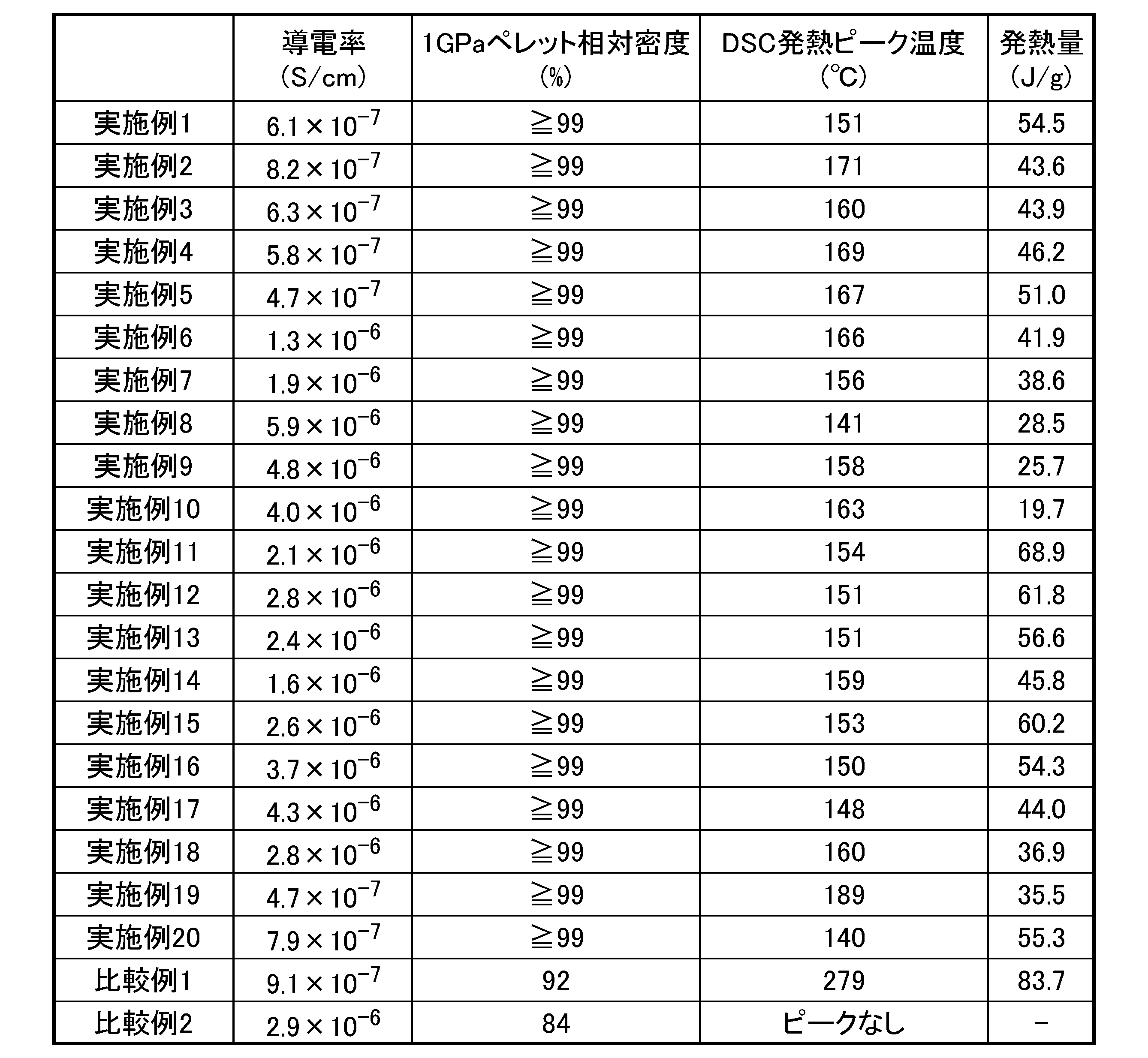


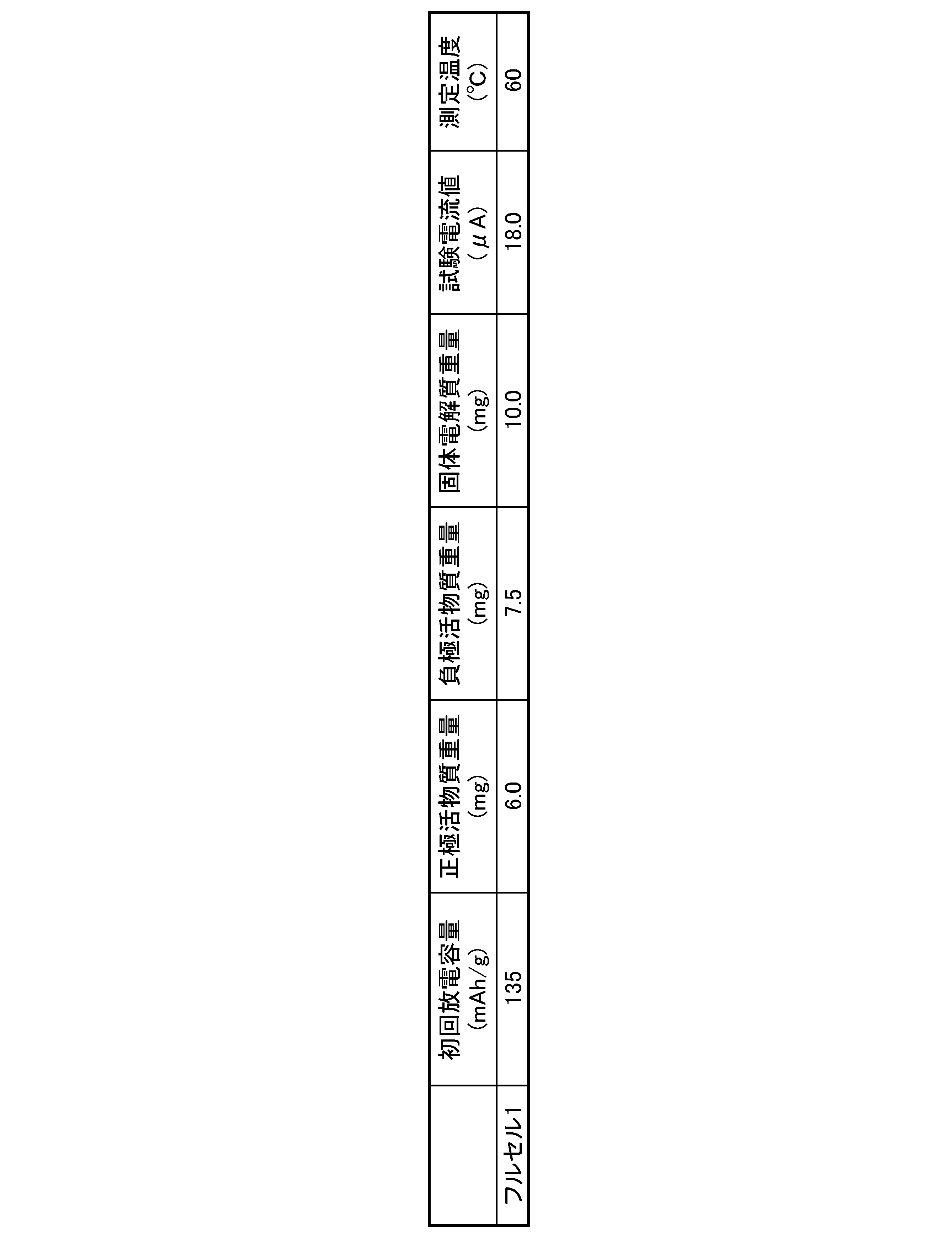
表1に示す通り、実施例1~20酸化物固体電解質は、Li2SO4とLi2CO3とを含み、Li2SO4とLi2CO3とのモル比が20:80~80:20であり、DSC曲線において、200℃以下の発熱ピークを有していたので、常温、1GPaプレスによって得られたペレットの相対密度が95%以上となった。また、実施例1~20酸化物固体電解質は、導電率が1.0×10⁻⁷S/cm以上であった。
一方、比較例1および2の固体電解質は、DSC曲線において、200℃以下の発熱ピークがなかった。そのため、常温、1GPaプレスによって得られたペレットの相対密度が95%未満であり、常温での変形性が劣位であった。
表2~4に示すように、実施例の酸化物固体電解質を用いた正極合材1~6は、比較正極合材1~3と比較して、優れた電池特性を有していた。また、同様に実施例の酸化物固体電解質を用いた負極合材およびフルセルも優れた電池特性を有していた。
本開示の酸化物固体電解質は全固体リチウムイオン電池の正極、負極、固体電解質層として使用することで、良好な電池特性を示す正極、負極、及び、固体電解質層、さらに、フルセルを常温プレスのみで作製することができる。非常に簡便な方法で電極やフルセルを形成できるため、本発明の酸化物固体電解質、及びそれを用いた電極合材は量産に適した材料であるので、産業上の利用可能性が高い。
11 固体電解質層、12 正極活物質層、13 負極活物質層、14 正極集電体、15 負極集電体、100 全固体リチウムイオン電池
Claims (8)
- 硫酸リチウム(Li2SO4)と炭酸リチウム(Li2CO3)とを含む複合物であって、
前記硫酸リチウムと前記炭酸リチウムとのモル比(Li2SO4:Li2CO3)が20:80~80:20であり、
示差走査熱量測定で得られる曲線において、発熱ピークの位置が200℃以下であり、
導電率が1.0×10⁻⁷S/cm以上である、酸化物固体電解質。 - 塩化リチウム、臭化リチウム、ヨウ化リチウム、ホウ酸リチウム、リン酸リチウム、硝酸リチウム、ケイ酸リチウム、およびアルミン酸リチウムからなる群より選択される少なくとも1種をさらに含む、請求項1に記載の酸化物固体電解質。
- 請求項1または2に記載の酸化物固体電解質と、
電極活物質と、
導電材と、
を含み、
前記酸化物固体電解質と、前記電極活物質と、前記導電材と、の質量比(酸化物固体電解質:電極活物質:導電材)が20~80:20~80:0~30である、電極合材。 - 請求項1または2に記載の酸化物固体電解質を含む、全固体リチウムイオン電池。
- 前記酸化物固体電解質を含む固体電解質層を備える、請求項4に記載の全固体リチウムイオン電池。
- 前記酸化物固体電解質を含む正極活物質層、または前記酸化物固体電解質を含む負極活物質層を備える、請求項4または5に記載の全固体リチウムイオン電池。
- 前記正極活物質層が、前記酸化物固体電解質、正極活物質および正極導電材を含み、 前記酸化物固体電解質と、前記正極活物質と、前記正極導電材と、の質量比(酸化物固体電解質:正極活物質:正極導電材)が20~80:20~80:0~30である、請求項6に記載の全固体リチウムイオン電池。
- 前記負極活物質層が、前記酸化物固体電解質、負極活物質および負極導電材を含み、 前記酸化物固体電解質と、前記負極活物質と、前記負極導電材と、の質量比(酸化物固体電解質:負極活物質:負極導電材)が20~80:20~80:0~30である、請求項6または7に記載の全固体リチウムイオン電池。
Applications Claiming Priority (2)
| Application Number | Priority Date | Filing Date | Title |
|---|---|---|---|
| JP2021-002328 | 2021-01-08 | ||
| JP2021002328A JP7634256B2 (ja) | 2021-01-08 | 2021-01-08 | 酸化物固体電解質、電極合材、および全固体リチウムイオン電池 |
Publications (1)
| Publication Number | Publication Date |
|---|---|
| WO2022149477A1 true WO2022149477A1 (ja) | 2022-07-14 |
Family
ID=82357715
Family Applications (1)
| Application Number | Title | Priority Date | Filing Date |
|---|---|---|---|
| PCT/JP2021/047806 Ceased WO2022149477A1 (ja) | 2021-01-08 | 2021-12-23 | 酸化物固体電解質、電極合材、および全固体リチウムイオン電池 |
Country Status (2)
| Country | Link |
|---|---|
| JP (1) | JP7634256B2 (ja) |
| WO (1) | WO2022149477A1 (ja) |
Citations (2)
| Publication number | Priority date | Publication date | Assignee | Title |
|---|---|---|---|---|
| WO2016067631A1 (ja) * | 2014-10-31 | 2016-05-06 | 出光興産株式会社 | 硫化物ガラス及び結晶性固体電解質の製造方法、結晶性固体電解質、硫化物ガラス及び固体電池 |
| JP2020064701A (ja) * | 2017-01-13 | 2020-04-23 | 株式会社日立製作所 | 全固体電池、およびその製造方法 |
-
2021
- 2021-01-08 JP JP2021002328A patent/JP7634256B2/ja active Active
- 2021-12-23 WO PCT/JP2021/047806 patent/WO2022149477A1/ja not_active Ceased
Patent Citations (2)
| Publication number | Priority date | Publication date | Assignee | Title |
|---|---|---|---|---|
| WO2016067631A1 (ja) * | 2014-10-31 | 2016-05-06 | 出光興産株式会社 | 硫化物ガラス及び結晶性固体電解質の製造方法、結晶性固体電解質、硫化物ガラス及び固体電池 |
| JP2020064701A (ja) * | 2017-01-13 | 2020-04-23 | 株式会社日立製作所 | 全固体電池、およびその製造方法 |
Also Published As
| Publication number | Publication date |
|---|---|
| JP7634256B2 (ja) | 2025-02-21 |
| JP2022107399A (ja) | 2022-07-21 |
Similar Documents
| Publication | Publication Date | Title |
|---|---|---|
| US10283758B2 (en) | Positive-electrode mixture, manufacturing method therefor, and all-solid-state lithium-sulfur battery | |
| JP6164812B2 (ja) | 全固体リチウムイオン二次電池 | |
| JP6313491B2 (ja) | 全固体リチウム硫黄電池およびその製造方法 | |
| US9865873B2 (en) | Positive electrode mixture and all-solid-state lithium sulfur cell | |
| JP5534000B2 (ja) | 全固体二次電池用電極活物質および全固体二次電池 | |
| JP5880409B2 (ja) | 全固体リチウム二次電池の製造方法 | |
| CN110498611A (zh) | 硫化物系固体电解质、该硫化物系固体电解质的制造方法和全固体电池的制造方法 | |
| JP7042426B2 (ja) | 固体電解質、および、電池 | |
| JP5276795B2 (ja) | 非水電解質二次電池用正極活物質およびそれを用いた非水電解質二次電池 | |
| JP2014029777A (ja) | 全固体電池 | |
| JPWO2019212026A1 (ja) | イオン伝導性粉末、イオン伝導性成形体および蓄電デバイス | |
| WO2023140311A1 (ja) | 全固体電池用正極、並びに全固体電池およびその製造方法 | |
| JP7616715B2 (ja) | 全固体リチウムイオン電池用電極複合体の製造方法 | |
| JP6936661B2 (ja) | 全固体電池の製造方法 | |
| JP6648649B2 (ja) | 全固体リチウム硫黄電池の製造方法 | |
| JPWO2011093129A1 (ja) | 全固体二次電池用電極活物質およびそれを用いた全固体二次電池 | |
| JP2005340078A (ja) | リチウムイオン二次電池用活物質、その製造方法およびリチウムイオン二次電池 | |
| JP7719140B2 (ja) | 正極活物質及びリチウムイオン二次電池 | |
| JP7634256B2 (ja) | 酸化物固体電解質、電極合材、および全固体リチウムイオン電池 | |
| WO2025070676A1 (ja) | カルシウムイオン二次電池用固体電解質およびカルシウムイオン二次電池 | |
| JP2025535305A (ja) | 全固体電池用正極及びそれを含む全固体電池 | |
| JP2021068663A (ja) | 正極材料の製造方法 | |
| EP4358186A1 (en) | Positive electrode material and battery | |
| JP7147708B2 (ja) | 正極合材 | |
| WO2021177382A1 (ja) | 正極材料および電池 |
Legal Events
| Date | Code | Title | Description |
|---|---|---|---|
| 121 | Ep: the epo has been informed by wipo that ep was designated in this application |
Ref document number: 21917697 Country of ref document: EP Kind code of ref document: A1 |
|
| NENP | Non-entry into the national phase |
Ref country code: DE |
|
| 122 | Ep: pct application non-entry in european phase |
Ref document number: 21917697 Country of ref document: EP Kind code of ref document: A1 |