WO2022149266A1 - 耐食性診断器、耐食性診断器の製造方法および耐食性診断方法 - Google Patents
耐食性診断器、耐食性診断器の製造方法および耐食性診断方法 Download PDFInfo
- Publication number
- WO2022149266A1 WO2022149266A1 PCT/JP2021/000522 JP2021000522W WO2022149266A1 WO 2022149266 A1 WO2022149266 A1 WO 2022149266A1 JP 2021000522 W JP2021000522 W JP 2021000522W WO 2022149266 A1 WO2022149266 A1 WO 2022149266A1
- Authority
- WO
- WIPO (PCT)
- Prior art keywords
- corrosion resistance
- base material
- metal
- corrosion
- diagnosed
- Prior art date
- Legal status (The legal status is an assumption and is not a legal conclusion. Google has not performed a legal analysis and makes no representation as to the accuracy of the status listed.)
- Ceased
Links
Images





Classifications
-
- G—PHYSICS
- G01—MEASURING; TESTING
- G01N—INVESTIGATING OR ANALYSING MATERIALS BY DETERMINING THEIR CHEMICAL OR PHYSICAL PROPERTIES
- G01N17/00—Investigating resistance of materials to the weather, to corrosion, or to light
- G01N17/04—Corrosion probes
Definitions
- This disclosure relates to a corrosion resistance diagnostic device, a method for manufacturing a corrosion resistance diagnostic device, and a method for diagnosing corrosion resistance.
- the form of corrosion in aluminum members is micrometer-order local corrosion. For this reason, the progress of local corrosion is not a major problem in aluminum members used for household window frames and the like.
- heat exchangers in which aluminum members are used for heat transfer tubes are applied to refrigeration cycle devices.
- a through hole may be formed in the heat transfer tube.
- the refrigerant gas leaks from the through hole of the heat transfer tube, which may lead to a product failure. Therefore, there is a demand for a technique for grasping the progress of corrosion of the heat transfer tube.
- the progress of corrosion of the heat transfer tube may be affected by the installation environment of the heat exchanger. Therefore, a technique for grasping the influence of the installation environment on corrosion is required.
- the corrosion-resistant life diagnostic component (corrosion-resistant diagnostic device) described in Japanese Patent No. 6058154 is a plate-shaped base material having an aluminum layer on the surface and a zinc-aluminum alloy formed on the base material. It has a configured sacrificial anode layer. The surface of the base metal has a base metal exposed portion where aluminum is exposed.
- This corrosion resistant life diagnostic component is attached to a heat exchanger that includes a heat transfer tube.
- the heat transfer tube is made of aluminum.
- a heat exchanger sacrificial anode layer made of zinc is formed on the outer surface of the heat transfer tube. Therefore, the surface of the corrosion-resistant life diagnostic component is made of the same material as the surface of the heat exchanger, which is the material to be diagnosed. Therefore, the life of the product in the installation environment is diagnosed by observing the corrosion generated in the corrosion-resistant life diagnosis component attached to the heat exchanger which is the product.
- the surface of the base material of the corrosion resistance diagnostic device (corrosion resistance life diagnostic component) described in the above document is made of the same material as the material to be diagnosed. Therefore, the progress of corrosion occurring in the corrosion resistance diagnostic device takes the same time as the progress of corrosion occurring in the material to be diagnosed. Therefore, it takes time to diagnose the corrosion resistance of the material to be diagnosed.
- the present disclosure has been made in view of the above problems, and an object thereof is to provide a corrosion resistance diagnostic device, a corrosion resistance diagnostic method, and a method for manufacturing a corrosion resistance diagnostic device, which can reduce the time required for diagnosing the corrosion resistance of the material to be diagnosed. It is to be.
- the corrosion resistance diagnostic device of the present disclosure is a corrosion resistance diagnostic device for diagnosing the corrosion resistance of the material to be diagnosed.
- the corrosion resistance diagnostic device includes a base material, a support, and a metal part.
- the base material contains a surface.
- the surface is made of a first metal, which is the same as the material of the material to be diagnosed.
- the support is placed on the surface of the base metal.
- the metal portion is supported on the surface of the base metal by a support.
- the metal part contains a second metal.
- the second metal in the metal portion has an electrochemically noble potential than the first metal on the surface of the base metal.
- the second metal in the metal portion has an electrochemically noble potential than the first metal on the surface of the base metal. Therefore, the progress of corrosion generated on the surface of the base metal is promoted by the metal portion. Therefore, it is possible to reduce the time required for diagnosing the corrosion resistance of the material to be diagnosed.
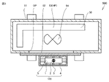
- FIG. 1 It is sectional drawing which shows schematic the structure of the outdoor unit which attached the corrosion resistance diagnostic apparatus which concerns on Embodiment 1.
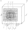
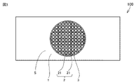
- FIG. It is a perspective view schematically showing the structure of the outdoor unit to which the corrosion resistance diagnostic apparatus which concerns on Embodiment 1 is attached. It is a top view which shows schematic structure of the corrosion resistance diagnostic apparatus which concerns on Embodiment 1.
- FIG. It is a side view which shows schematic structure of the corrosion resistance diagnostic apparatus which concerns on Embodiment 1.
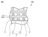
- FIG. It is an enlarged view of the V region of FIG.
- It is sectional drawing which shows typically the base material, the metal part and the liquid of the corrosion resistance diagnostic apparatus which concerns on Embodiment 1.
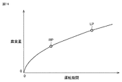
- FIG. 3 is a perspective view schematically showing another configuration of the heat transfer tube according to the first embodiment. It is a block diagram which shows schematic structure of the air conditioner which concerns on Embodiment 2. It is a perspective view schematically showing the structure of the outdoor unit to which the corrosion resistance diagnostic apparatus which concerns on Embodiment 3 is attached. It is a graph which shows the relationship between the operation time of an outdoor unit and the amount of corrosion.
- Embodiment 1 The configuration of the corrosion resistance diagnostic apparatus 100 according to the first embodiment will be described with reference to FIGS. 1 to 5.
- the corrosion resistance diagnostic device 100 is a corrosion resistance diagnostic device 100 for diagnosing the corrosion resistance of the material to be diagnosed 50.
- the material to be diagnosed 50 may corrode.
- the material to be diagnosed 50 may be corroded by salt damage.
- Factors of salt damage are, for example, chloride ions, temperature, humidity and the like.
- the form of corrosion such as the shape, traveling speed, and position of corrosion that occurs in the material 50 to be diagnosed is affected by the environment (installation environment) in which the material 50 to be diagnosed is installed.
- the installation environment is an environment in which the material to be diagnosed 50 is placed.
- the installation environment is also called the actual environment.
- the corrosion resistance diagnostic device 100 according to the present embodiment is configured to diagnose the corrosion resistance of the material to be diagnosed 50 by grasping the corrosion form of the material to be diagnosed 50 in the installation environment.
- the material to be diagnosed 50 is the heat transfer tube HP of the outdoor unit 500 of the air conditioner.
- the heat transfer tube HP is mounted on the heat exchanger 53.
- the heat exchanger 53 is mounted on the outdoor unit 500 of the air conditioner.
- the material to be diagnosed 50 is a heat transfer tube HP made of an aluminum material with a zinc sacrificial layer.
- the material 50 to be diagnosed is not limited to the heat transfer tube HP. The detailed configuration of the air conditioner and the aluminum material with the zinc sacrificial layer will be described later.
- the outdoor unit 500 includes a housing 51, a fan guard 52, a heat exchanger 53, and a fan 54.
- FIG. 1 is a cross-sectional view taken along the line I-I of FIG.
- a heat exchanger 53 and a fan 54 are arranged inside the housing 51.
- the housing 51 is provided with an opening OP.
- the fan guard 52 is attached to the housing 51 so as to cover the opening OP of the housing 51.
- the fan guard 52 has a mesh shape (see FIG. 2).
- a corrosion resistance diagnostic device 100 is attached to the fan guard 52.
- the heat exchanger 53 includes a heat transfer tube HP, which is the material to be diagnosed 50 in the present embodiment.
- the fan 54 is configured to generate an air flow flowing from the heat exchanger 53 toward the opening OP. This cools the heat exchanger 53.
- the corrosion resistance diagnostic device 100 is attached to the outdoor unit 500 on which the material to be diagnosed 50 is mounted. Therefore, the corrosion resistance diagnostic device 100 is installed in the installation environment. Therefore, the environment in which the material to be diagnosed 50 is installed is the same as the environment in which the material to be diagnosed 50 is installed. Desirably, the corrosion resistance diagnostic device 100 is installed in the installation environment together with the material to be diagnosed 50.
- the corrosion resistance diagnostic device 100 includes a base material 1, a metal portion 2, and a support 3.
- the corrosion resistance diagnostic device 100 may further include a holding portion 4.
- the base material 1 is, for example, a plate-shaped metal member.
- the base material 1 is separate from the material to be diagnosed 50. Therefore, the base material 1 is separated from the material to be diagnosed 50. Further, in the present embodiment, the base material 1 is arranged away from the material to be diagnosed 50.
- the base material 1 contains the surface S. During the diagnosis of the corrosion resistance of the material to be diagnosed 50, the surface S of the base material 1 is corroded. Further, in the diagnosis of the corrosion resistance of the material to be diagnosed 50, the corrosion generated on the surface S of the base material 1 progresses.
- the surface S is made of a first metal which is the same as the material of the material to be diagnosed 50.
- the entire base material 1 may be made of a first metal which is the same as the material of the material to be diagnosed 50.
- the first metal comprises aluminum.
- the first metal is, for example, an aluminum (Al) -zinc (Zn) alloy.
- the first metal is not limited to this, and may be appropriately determined as long as it is the same as the material of the material to be diagnosed 50.
- the base material 1 is configured to be movable with respect to the material to be diagnosed 50.
- the base material 1 is configured to move with respect to the material to be diagnosed 50 before and after the diagnosis of the corrosion resistance of the material to be diagnosed 50.
- the base material 1 may be configured so as not to move with respect to the material to be diagnosed 50 during the diagnosis of the corrosion resistance of the material to be diagnosed 50.
- the metal part 2 is supported by the support 3 on the surface S of the base material 1.
- the metal portion 2 is in contact with the surface S of the base metal 1.
- the metal portion 2 is in direct contact with the surface S of the base metal 1.
- the metal portion 2 contains a second metal.
- the outer surface of the metal portion 2 is made of a second metal.
- the entire metal portion 2 may be made of a second metal.
- the second metal of the metal portion 2 has an electrochemically noble potential than that of the first metal on the surface S of the base material 1.
- the first metal is aluminum (Al)
- the second metal is, for example, copper (Cu), iron (Fe), or the like.
- the combination of the first metal and the second metal is not limited to the above combination, and can be appropriately determined as long as the second metal has an electrochemically noble potential than that of the first metal. You may.
- the fact that the second metal has an electrochemically noble potential than that of the first metal means that the ionization tendency of the second metal is higher than the ionization tendency of the first metal. Is also small.
- the metal portion 2 is for causing corrosion in the portion of the surface S of the base material 1 in contact with the metal portion 2.
- the metal portion 2 is for accelerating the corrosion generated in the portion of the surface S of the base material 1 in contact with the metal portion 2.
- the metal portion 2 contains the metal powder 21.
- the metal powder 21 has a larger specific gravity than the support 3.
- the metal powder 21 is an iron powder or a copper powder made of iron (Fe) or copper (Cu) that is likely to exist in the installation environment of the outdoor unit 500. In this case, the progress of corrosion of the heat transfer tube HP (diagnosed material 50) mounted on the outdoor unit 500 can be evaluated more accurately.
- the support 3 is arranged on the surface S of the base material 1.
- the support 3 is in contact with the surface S of the base material 1.
- the support 3 is configured to support the metal portion 2 in a state where the metal portion 2 is in contact with the surface S of the base material 1.
- the support 3 is configured to support the metal powder 21 in a state where the metal powder 21 is in contact with the surface S of the base material 1.
- the support 3 is provided with a hole 31.
- the support 3 may be provided with a plurality of holes 31. That is, the support 3 may be a porous object (porous body).
- the holes 31 are provided in the support 3 so as to face the surface S of the base material 1.
- the support 3 can hold the gas GAS, the liquid LQ, and the metal portion 2 in the pores 31.
- the metal powder 21 may be held by the support 3 in each of the plurality of holes 31.
- the gas GAS is, for example, air (atmosphere).
- the liquid LQ is, for example, water ( H2O ). Water (H 2 O) is tap water, pure water, or the like.
- the support 3 is a conductor.
- the conductivity of the support 3 is 10 mS / m or more. It is desirable that the conductivity of the support 3 is higher than that of the liquid LQ held in the pores 31. Specifically, it is desirable that the conductivity of the support 3 is higher than that of water ( H2O ). The conductivity of water (H 2 O) is 10 mS / m.
- the support 3 consists of agar and a non-corrosive electrolyte salt.
- the support 3 consists of agar and potassium nitrate (KNO 3 ).
- KNO 3 potassium nitrate
- Agar contains water. Therefore, the support 3 made of agar and a non-corrosive electrolyte salt has a conductivity higher than that of water ( H2O ). Therefore, electrons and ions easily move through the agar.
- the non-corrosive electrolyte salt keeps the balance between positive and negative values.
- the non-corrosive electrolyte salt facilitates the transfer of positive and negative values.
- the non-corrosive electrolyte salt is, for example, potassium nitrate (KNO 3 ).
- the non-corrosive electrolyte salt is not limited to potassium nitrate (KNO 3 ).
- Non-corrosive electrolyte salts do not corrode metals. Therefore, the non-corrosive electrolyte salt does not affect the corrosive reaction.
- Potassium chloride (KCl) which is a corrosive electrolyte salt, is not desirable.
- the material of the support 3 is not limited to agar, and may be a polymer material such as a water-absorbing polymer.
- a polymer material such as a water-absorbing polymer.
- a typical example of a water-absorbing polymer is sodium polyacrylate.
- the gas GAS, the liquid LQ, and the metal portion 2 are in contact with the surface S of the base material 1 while being held in the pores 31 of the support 3. As a result, a gas-liquid solid three-phase interface is formed on the surface S of the base material 1.
- the gas-liquid solid three-phase interface is an interface in which a gas GAS, a liquid LQ, and a solid are in contact with each other.
- the gas GAS and the liquid LQ at the gas-liquid solid three-phase interface are air and water ( H2O ).
- the solid at the gas-liquid solid three-phase interface is the metal powder 21.
- the holding portion 4 holds the base material 1.
- the holding portion 4 includes a cage portion 41 and a hook portion 42.
- the basket portion 41 holds the base material 1.
- the hook portion 42 is configured to be removable from the outdoor unit 500. Specifically, the hook portion 42 is configured to be mountable to the outdoor unit 500 by being locked to the fan guard 52.
- the method for manufacturing the corrosion resistance diagnostic device 100 is a method for manufacturing the corrosion resistance diagnostic device 100 for diagnosing the corrosion resistance of the material to be diagnosed 50.
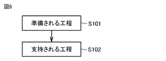
- the method for manufacturing the corrosion resistance diagnostic device 100 includes a prepared step S101 and a supported step S102.
- the base material 1, the metal portion 2, and the support 3 are prepared. Further, the holding portion 4 may be prepared.
- the metal portion 2 is supported by the surface S of the base material 1 by the support 3.
- the metal portion 2 in the step S102 (see FIG. 6) in which the metal portion 2 is supported by the surface S of the base material 1, the metal portion 2 is arranged on the surface S of the base material 1, and then the metal is formed by the support 3. The portion 2 is fixed to the surface S of the base metal 1.
- the support 3 consists of agar and a non-corrosive electrolyte salt
- the agar and the non-corrosive electrolyte salt added to the solvent water ( H2O ) are heated over low heat.
- the non-corrosive electrolyte salt may be potassium nitrate (KNO 3 ). This dissolves the agar and non-corrosive electrolyte salts, resulting in a solution.
- the metal portion 2 is arranged on the surface S of the base material 1.
- the solution is poured onto the metal powder 21 of the metal portion 2 arranged on the surface S of the base material 1.
- the metal powder 21 is once dispersed in the solution.
- the metal portion 2 since the metal portion 2 has a higher specific gravity than the support 3, the metal portion 2 sinks in the support 3. As a result, the metal portion 2 comes into contact with the surface S of the base material 1 while being supported by the support 3.
- the metal portion 2 is transferred to the surface of the base material 1 by the support 3. It may be fixed to S. That is, the metal portion 2 may be fixed to the surface S of the base material 1 integrally with the support 3.
- the corrosion resistance diagnostic device 100 is manufactured. Subsequently, in the present embodiment, as shown in FIG. 2, the manufactured corrosion resistance diagnostic device 100 is attached to the outdoor unit 500. Specifically, the cage portion 41 of the holding portion 4 holds the base material 1. The hook portion 42 of the holding portion 4 is locked to the fan guard 52. As a result, the corrosion resistance diagnostic device 100 is attached to the outdoor unit 500.
- the base metal 1 and the metal portion 2 are in direct contact with each other. Further, the base material 1 and the metal portion 2 are also connected via a liquid LQ which is water ( H2O ). In this embodiment, the connection via the liquid LQ is sometimes referred to as a liquid junction.
- the base material 1 is an aluminum (Al) -zinc (Zn) alloy
- the following reaction proceeds on the surface S of the base material 1 which is the anode.
- the oxidation reaction of aluminum (Al) and zinc (Zn) proceeds on the surface S of the base material 1. Further, in the metal portion 2, the reduction reaction of water (H 2 O) and oxygen (O 2 ) proceeds.
- the oxidation reaction on the surface S of the base material 1 is a reaction for dissolving a metal. That is, the oxidation reaction on the surface S of the base material 1 is a corrosion reaction.
- the driving force of the oxidation reaction (corrosion reaction) in the present embodiment is the difference between the electrochemical potential of the base material 1 and the electrochemical potential of the metal portion 2.
- the second metal of the metal part 2 since the second metal of the metal part 2 has an electrochemically noble potential than the metal of the base material 1, the electrochemical potential of the base material 1 and the electricity of the metal part 2 are obtained. There is a difference with the chemical potential.
- the higher the electrochemical potential of the metal part 2 with respect to the base material 1 which is aluminum (Al) the larger the difference in the electrochemical potential between the base material 1 and the metal part 2.
- copper (Cu) has a higher electrochemical potential than iron (Fe)
- the difference in chemical potential is large.
- the corrosion resistance diagnosis method is a corrosion resistance diagnosis method for diagnosing the corrosion resistance of the material to be diagnosed 50.
- the corrosion resistance diagnostic device 100 of the present disclosure is used.
- the progress of corrosion occurring in the material to be diagnosed 50 is grasped based on the progress of corrosion occurring in the base material 1 exposed to the installation environment.
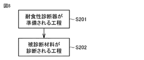
- the corrosion resistance diagnosis method includes a step S201 in which the corrosion resistance diagnostic device 100 is prepared and a step S202 in which the corrosion resistance is diagnosed.
- the corrosion resistance diagnostic device 100 is prepared in the step S201 (see FIG. 8) in which the corrosion resistance diagnostic device 100 is prepared.
- the prepared corrosion resistance diagnostic device 100 is exposed to the installation environment. As a result, the surface S of the base material 1 is corroded. Further, the progress of corrosion generated on the surface S of the base material 1 is promoted by the metal portion 2. As a result, the corrosion reaction proceeds on the surface S of the base material 1. Corrosion reduces the thickness of the base metal 1. Therefore, the volume of the base material 1 is reduced. In addition, corrosion produces corrosion products in the base metal 1. Further, the surface S of the base material 1 is discolored due to corrosion.
- the corrosion resistance of the material to be diagnosed 50 is diagnosed by quantifying the amount of corrosion of the base material 1.
- the amount of corrosion of the base material 1 is quantified by a decrease in volume and weight of the base material 1, corrosion products, discoloration of the surface S, and the like.
- the amount of corrosion of the base material 1 is measured by measuring the volume of the corroded portion of the base material 1 by X-ray CT. Is quantified. That is, the progress of corrosion in the base material 1 is quantified by the amount of decrease in the volume of the base material 1.
- the method for quantifying the amount of corrosion of the base material 1 is not limited to the method by X-ray CT, as will be described later.
- the amount of decrease in the volume of the base material 1 is measured, for example, by grasping the internal structure of the base material 1 in the depth direction.
- X-ray CT X-Ray Computed Tomography
- X-rays are irradiated toward the object (base material 1).
- the X-rays applied to the base material 1 pass through the base material 1. Defects such as the internal state, structure, and corrosion of the base material 1 are evaluated based on the transmitted X-rays.
- the amount of X-ray transmission differs due to the difference between the metal oxide in the corroded portion and the metal material in the non-corroded portion.
- the difference in the amount of X-ray transmission occurs in the image as a difference in shading. This clarifies the region of the corroded portion in the cross section of the base metal 1.
- a plurality of cross sections of the base material 1 are photographed by X-rays. By integrating each of the images of a plurality of cross sections, the volume of the corroded portion can be grasped. In integrating images of a plurality of cross sections, the pitch between the cross sections is taken into consideration.
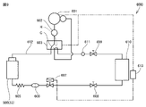
- the air conditioner 600 includes a compressor 601, a muffler 602, a four-way valve 603, an outdoor unit 500 including a heat exchanger 53 (outdoor heat exchanger) arranged outdoors, a capillary tube 605, and a strainer. It includes an electronically controlled expansion valve 607, a first stop valve 608, a second stop valve 609, an indoor heat exchanger 610, an auxiliary muffler 611, a refrigerant pipe 612, and an air conditioner side control unit 613.
- the refrigerant pipe 612 includes a compressor 601, a muffler 602, a four-way valve 603, a heat exchanger 53, a capillary tube 605, a strainer 606, an electronically controlled expansion valve 607, a first stop valve 608, a second stop valve 609, and an indoor heat exchanger. It is connected to the 610 and the auxiliary muffler 611.
- a refrigerant circuit is configured by connecting each element to the refrigerant pipe 612.
- the air conditioner side control unit 613 is mounted on the indoor unit.
- the air conditioner side control unit 613 is electrically connected to the compressor 601 and the four-way valve 603 and the electronically controlled expansion valve 607. In FIG. 9, the electrical connection is shown by an alternate long and short dash line.
- the air conditioner side control unit 613 is configured to control actuators such as the compressor 601 and the electronically controlled expansion valve 607 based on the temperatures of the outside air, the room, the refrigerant, and the like.
- the air conditioner side control unit 613 is configured to further control the four-way valve 603.
- the air conditioner side control unit 613 is configured to control the four-way valve 603 so that the four-way valve 603 switches the refrigerating cycle of the cooling C and the heating H.
- the liquid refrigerant compressed by the compressor 601 becomes a high-temperature and high-pressure gaseous refrigerant.
- the gaseous refrigerant flows into the heat exchanger 53 through the four-way valve 603.
- the gaseous refrigerant flowing into the heat exchanger 53 exchanges heat with the outdoor air passing through the heat exchanger 53. That is, the gaseous refrigerant flowing into the heat exchanger 53 is dissipated.
- the gaseous refrigerant becomes a high-pressure liquid refrigerant by heat exchange.
- the liquid refrigerant flows out of the heat exchanger 53.
- the high-pressure liquid refrigerant flowing out of the heat exchanger 53 is depressurized by the capillary tube 605 and the electronically controlled expansion valve 607. As a result, the high-pressure liquid refrigerant becomes a low-pressure gas-liquid two-phase refrigerant.
- the low-pressure gas-liquid two-phase refrigerant flows into the indoor heat exchanger 610.
- the gas-liquid two-phase refrigerant flowing into the indoor heat exchanger 610 exchanges heat with the indoor air passing through the indoor heat exchanger 610. This cools the room air.
- the gas-liquid two-phase refrigerant is a low-temperature and low-pressure gaseous refrigerant.
- the low temperature and low pressure gaseous refrigerant is sucked into the compressor 601.
- the operation of the air conditioner 600 including the heat transfer tube HP (see FIG. 1), which is the material to be diagnosed 50 (see FIG. 1) in the present embodiment, during the heating operation will be described.
- the refrigerant is compressed by the compressor 601 to become a high-temperature and high-pressure gaseous refrigerant as in the cooling operation. Become.
- the high temperature and high pressure gaseous refrigerant flows into the indoor heat exchanger 610 through the four-way valve 603.
- the high-temperature and high-pressure gaseous refrigerant flowing into the indoor heat exchanger 610 exchanges heat with the indoor air passing through the indoor heat exchanger 610. This heats the room air. Further, the high-temperature and high-pressure gaseous refrigerant becomes a high-pressure liquid refrigerant.
- the high-pressure liquid refrigerant flowing out of the indoor heat exchanger 610 is depressurized by the electronically controlled expansion valve 607 and the capillary tube 605. As a result, the high-pressure liquid refrigerant becomes a low-pressure gas-liquid two-phase refrigerant.
- the low-pressure gas-liquid two-phase refrigerant flows into the heat exchanger 53.
- the low-pressure gas-liquid two-phase refrigerant flowing into the heat exchanger 53 exchanges heat with the outdoor air passing through the heat exchanger 53.
- the low-pressure gas-liquid two-phase refrigerant becomes a low-temperature and low-pressure gaseous refrigerant.
- the gaseous refrigerant is sucked into the compressor 601.
- the heat transfer tube HP includes the core material layer HP1 and the sacrificial layer HP2.
- the core material layer HP1 is provided with a flow path OP1 that penetrates the core material layer HP1 along the longitudinal direction of the heat transfer tube HP.
- the sacrificial layer HP2 is provided on the core material layer HP1.
- the core layer HP1 has an electrochemically noble potential than the sacrificial layer HP2.
- the core material layer HP1 is, for example, an aluminum (Al) -manganese (Mn) alloy.
- the sacrificial layer HP2 is, for example, an aluminum (Al) -zinc (Zn) alloy.
- the aluminum (Al) material provided with the core material layer HP1 of the aluminum (Al) alloy and the sacrificial layer HP2 of zinc (Zn) is also referred to as an aluminum material with a zinc sacrificial layer.
- the zinc (Zn) sacrificial layer HP2 contains an aluminum (Al) -zinc (Zn) alloy layer.
- the zinc (Zn) sacrificial layer HP2 is electrically lower than the core material layer HP1. Therefore, the zinc (Zn) sacrificial layer HP2 corrodes preferentially over the core material layer HP1. Therefore, it is suppressed that local corrosion occurs in the core material layer HP1. That is, the heat transfer tube HP is provided with an anticorrosion design using an aluminum material with a zinc sacrificial layer. Further, the corrosion resistance of the heat exchanger 53 is further improved by providing the zinc (Zn) sacrificial layer HP2 on the entire surface S of the core material layer HP1. For example, when an aluminum material with a zinc sacrificial layer is used for the heat transfer tube HP, the product life of the outdoor unit 500 (see FIG. 1) for an air conditioner including the heat transfer tube HP is usually 10 years or more.
- the core material layer HP1 is provided with an exposed portion exposed from the sacrificial layer HP2. Even in this case, since the exposed portion is protected by the preferential corrosion of the sacrificial layer HP2, the deterioration of the corrosion resistance of the heat transfer tube HP is suppressed.
- the aluminum material with a zinc sacrificial layer of the heat transfer tube HP which is the material to be diagnosed 50, greatly affects the product life of the heat exchanger 53 (see FIG. 1) and the air conditioner 600 (see FIG. 9).
- the product life of the heat exchanger 53 and the air conditioner 600 can be grasped by diagnosing the corrosion resistance of the aluminum material with the zinc sacrificial layer of the heat transfer tube HP, which is the material to be diagnosed 50.
- the manufacturing method of aluminum material with zinc sacrificial layer is mainly as follows. First, an aluminum (Al) member is prepared as the core material layer HP1 using a material containing aluminum (Al). Next, the sacrificial layer HP2 is formed on the core material layer HP1. The corrosion resistance of the sacrificial layer HP2 is lower than that of the core material layer HP1. Specifically, the core material layer HP1 is an aluminum (Al) alloy.
- the aluminum material with a zinc sacrificial layer is not limited to the above manufacturing method.
- the aluminum material with a zinc sacrificial layer may be, for example, any one of an aluminum (Al) clad material, a zinc (Zn) sprayed aluminum (Al) material, and an aluminum (Al) material with a brazing material.
- the aluminum (Al) clad material is obtained by rolling and heat-treating the aluminum (Al) -manganese (Mn) alloy material which is the core material layer HP1 and the aluminum (Al) -zinc (Zn) alloy material which is the surface layer. ,
- the core material layer HP1 and the surface layer are clad and manufactured.
- Zinc (Zn) sprayed aluminum (Al) material is produced by heat-treating metallic zinc (Zn) sprayed on the core material layer HP1 of aluminum (Al) and diffusing it into the core material layer HP1.
- the aluminum (Al) -silicon (Si) -zinc (Zn) alloy contained in the brazing material is formed into the aluminum (Al) core layer HP1 by the heat treatment of brazing. Melts and diffuses.
- the molten and diffused zinc (Zn) component is diffused into the aluminum (Al) core material layer HP1 to produce an aluminum (Al) material with a brazing material layer.
- the heat transfer tube HP When the heat transfer tube HP has a cylindrical shape, the heat transfer tube HP is formed of an aluminum (Al) clad material or a zinc (Zn) sprayed aluminum (Al) material.
- the heat transfer tube HP of the heat exchanger 53 may have a shape called a flat tube.
- the outer shape of the flat tube is a flat shape in a cross-sectional view orthogonal to the longitudinal direction of the heat transfer tube HP. Further, a flat portion is provided on the outer shape of the flat tube.
- a plurality of flow paths OP1 are provided inside the flat tube.
- the heat exchanger 53 may be a fin tube type heat exchanger in which a heat transfer tube HP which is a flat tube and a fin material are combined. When the heat transfer tube HP of the heat exchanger 53 is a flat tube, the area inside the tube that the refrigerant contacts is larger than that of the cylindrical heat transfer tube HP.
- the ventilation resistance (pressure loss) is smaller than that of the cylindrical heat transfer tube HP.
- the heat transfer tube HP is a flat tube, it is difficult to apply an aluminum (Al) clad material. This is because the shape of the flat tube is complicated. Therefore, when the heat transfer tube HP is a flat tube, it is desirable to apply a zinc (Zn) sprayed aluminum (Al) material or an aluminum (Al) material with a brazing material layer.
- the brazing material containing zinc (Zn) may not wrap around the core material layer HP1 of the aluminum (Al).
- the core material layer HP1 is exposed from the zinc (Zn) sacrificial layer HP2.
- the waxy material layer containing zinc (Zn) also suppresses the corrosion of the core material layer HP1 exposed from the zinc (Zn) sacrificial layer HP2.
- the life of the aluminum material with a zinc sacrificial layer is determined by the concentration distribution of zinc (Zn) in the zinc (Zn) sacrificial layer HP2. Therefore, the sacrificial layer HP2 of zinc (Zn) is designed according to the product life.
- the corrosion resistance diagnostic device 100 in the present embodiment it is necessary that the ionization energy of the first metal is larger (base) than the ionization energy of the second metal.
- Aluminum (Al) has a relatively large ionization energy (base) among metals. Therefore, the corrosion resistance diagnostic device 100 in the present embodiment is suitable for application to the above-mentioned aluminum material with a zinc sacrificial layer. That is, the corrosion resistance diagnostic device 100 in the present embodiment is suitable for diagnosing the anticorrosion function of the aluminum material with the zinc sacrificial layer.
- the corrosion resistance diagnostic device 100 As shown in FIG. 5, the metal portion 2 is supported by the support 3 on the surface S of the base material 1.
- the second metal of the metal portion 2 has an electrochemically noble potential than that of the first metal on the surface S of the base material 1. Therefore, the progress of corrosion generated on the surface S of the base material 1 is promoted by the metal portion 2. Therefore, it is possible to reduce the time required for grasping the corrosion form of the material to be diagnosed 50 based on the amount of corrosion of the base material 1. Therefore, it is possible to reduce the time required for diagnosing the corrosion resistance of the material to be diagnosed 50.
- the rate at which the corrosion occurring on the surface S of the base material 1 progresses is the same as the rate at which the corrosion occurring on the surface S to be diagnosed progresses. Therefore, the amount of corrosion of the surface S of the base material 1 is the same as the amount of corrosion of the material to be diagnosed 50. Therefore, it takes time to grasp the corrosion form of the material to be diagnosed 50 based on the amount of corrosion of the base material 1.
- the time required for grasping the corrosion form of the material to be diagnosed 50 based on the amount of corrosion of the base material 1 is reduced. be able to.
- the corrosion generated on the surface S of the base material 1 is promoted, the amount of corrosion per hour is large. Therefore, even if the accuracy of the corrosion amount evaluation technique for evaluating the corrosion amount is not high, the corrosion generated on the surface S can be evaluated.
- the surface S is made of a first metal which is the same as the material of the material to be diagnosed 50.
- the corrosion resistance diagnostic device 100 is installed in the installation environment in which the material to be diagnosed 50 is installed. Therefore, the corrosion form of the corrosion generated in the base material 1 is the same as the corrosion form of the corrosion generated in the material to be diagnosed 50. Therefore, the corrosion form in the installation environment of the material to be diagnosed 50 can be estimated based on the corrosion form generated by the base material 1. Therefore, it is possible to grasp the corrosion form in the installation environment of the material 50 to be diagnosed. In addition, the corrosion form in the installation environment of the material 50 to be diagnosed can be accurately grasped.
- the conductivity of the support 3 is 10 mS / m or more. Therefore, the conductivity of the support 3 is equal to or higher than the conductivity of water ( H2O ). As a result, the electrons and ions of the base material 1 and the metal portion 2 are easily conducted to the base material 1 and the metal through the support 3. That is, the support 3 can carry the movement of electrons and ions of the base material 1 and the metal portion 2. As a result, the progress of corrosion generated on the surface S of the base material 1 is further promoted. Therefore, the time required for diagnosing the corrosion resistance of the material to be diagnosed 50 can be further reduced.
- the gas GAS, the liquid LQ, and the metal portion 2 are in contact with the surface S of the base material 1 while being held in the pores 31 of the support 3. That is, a gas-liquid solid three-phase interface is formed on the surface S of the base material 1. Therefore, oxygen (O 2 ) in the air, which is a gas GAS, and water (H 2 O), which is a liquid LQ, coexist on the surface S of the base material 1. Therefore, (O 2 ) and water (H 2 O) are easily supplied to the surface S of the base material 1. As a result, corrosion of the surface S of the base material 1 by the metal portion 2 is likely to occur. Further, the corrosion of the surface S of the base material 1 by the metal portion 2 is easily maintained. That is, the corrosion generated on the surface S of the base material 1 is further promoted. Therefore, the time required for diagnosing the corrosion resistance of the material to be diagnosed 50 can be further reduced.
- Support 3 is composed of agar and a non-corrosive electrolyte salt.
- Agar and non-corrosive electrolyte salts are inexpensive. Also, the availability of agar and non-corrosive electrolyte salts is high. Therefore, the support 3 can be manufactured inexpensively and easily.
- Support 3 is composed of agar and a non-corrosive electrolyte salt.
- the conductivity of agar is greater than or equal to the conductivity of water. Therefore, the progress of corrosion generated on the surface S of the base material 1 is further promoted by the agar.
- the non-corrosive electrolyte salt maintains a balance between the positive and negative values of ions and electrons moving between the base material 1 and the metal portion 2. Further, the non-corrosive electrolyte salt facilitates the movement of ions between the base material 1 and the metal portion 2. Therefore, the progress of corrosion generated on the surface S of the base material 1 is further promoted by the non-corrosive electrolyte salt.
- the progress of corrosion generated on the surface S of the base material 1 is further promoted by the support 3 made of agar and a non-corrosive electrolyte salt. Therefore, the time required for diagnosing the corrosion resistance of the material to be diagnosed 50 can be further reduced.
- Support 3 is composed of agar and a non-corrosive electrolyte salt. Therefore, it is possible to prevent the surface S of the base material 1 from being unintentionally corroded by the support 3.
- the first metal contains aluminum (Al). Therefore, when the material to be diagnosed 50 contains aluminum (Al), the corrosion form of the material to be diagnosed 50 can be grasped at an early stage.
- the metal portion 2 is formed on the surface of the base material 1 by the support 3. Supported by S.
- the second metal of the metal portion 2 has an electrochemically noble potential than that of the first metal on the surface S of the base material 1. Therefore, the progress of corrosion generated on the surface S of the base material 1 is promoted by the metal portion 2. Therefore, it is possible to reduce the time required for grasping the corrosion form of the material to be diagnosed 50 based on the amount of corrosion of the base material 1. Therefore, it is possible to reduce the time required for diagnosing the corrosion resistance of the material to be diagnosed 50.
- the metal portion 2 is fixed to the surface S of the base material 1 by the support 3. Therefore, the metal portion 2 can be reliably fixed at a position on the surface S of the base material 1 where it is particularly desired to grasp the corrosion form.
- the metal portion 2 is fixed to the surface S of the base material 1 by the support 3. Therefore, the metal portion 2 and the support 3 can be fixed to the surface S of the base material 1 in a state where the metal portion 2 and the support 3 are integrated. If the metal powder 21 is placed on the surface S of the base material 1 and then the support 3 fixes the metal portion 2 to the surface S, the metal portion 2 may fall off from the surface S of the base material 1. .. As a result, the weight of the metal portion 2 may be reduced.
- the metal portion 2 and the support 3 are fixed to the surface S of the base material 1 in a state where the metal portion 2 and the support 3 are integrated. Therefore, it is possible to prevent the metal portion 2 from falling off from the surface S of the base material 1. Therefore, it is possible to prevent the weight of the metal portion 2 fixed to the surface S of the base material 1 from decreasing.
- the metal portion 2 of the corrosion resistance diagnostic device 100 prepared in the step S201 (see FIG. 8) in which the corrosion resistance diagnostic device 100 is prepared is It is supported by the surface S of the base material 1.
- the second metal of the metal portion 2 has an electrochemically noble potential than that of the first metal on the surface S of the base material 1. Therefore, the progress of corrosion generated on the surface S of the base material 1 is promoted by the metal portion 2. Therefore, it is possible to reduce the time required for grasping the corrosion form of the material to be diagnosed 50 based on the amount of corrosion of the base material 1. Therefore, it is possible to reduce the time required for diagnosing the corrosion resistance of the material to be diagnosed 50.
- step S202 in which the corrosion resistance of the material to be diagnosed 50 is diagnosed, the amount of corrosion of the base material 1 is quantified by measuring the volume of the corroded portion of the base material 1 by X-ray CT.
- X-ray CT is a non-destructive inspection. Therefore, the amount of corrosion of the base material 1 can be quantified without damaging the corrosion resistance diagnostic device 100.
- Embodiment 2 Next, the configuration of the corrosion resistance diagnostic device 100 according to the second embodiment will be described with reference to FIG. 12. Unless otherwise specified, the second embodiment has the same configuration, manufacturing method, and action and effect as those of the first embodiment. Therefore, the same components as those in the first embodiment are designated by the same reference numerals, and the description thereof will not be repeated.
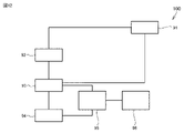
- the corrosion resistance diagnostic device 100 further includes a control unit 91, an imaging unit 92, a detection unit 93, a storage unit 94, a data comparison unit 95, and a notification unit 96.
- the control unit 91, the photographing unit 92, the detection unit 93, the storage unit 94, the data comparison unit 95, and the notification unit 96 are electrically connected.
- the control unit 91 is configured to control the photographing unit 92 and the detection unit 93.
- the control unit 91 is, for example, a CPU (Central Processing Unit) or the like.
- the photographing unit 92 is configured to photograph the surface S (see FIG. 1) of the base material 1 based on the control signal of the control unit 91.
- the photographing unit 92 is configured to transmit the image data photographed by the photographing unit 92 to the detection unit 93.
- the photographing unit 92 is an photographing means such as a digital camera or a television camera, for example.
- the detection unit 93 is configured to obtain a digital image signal by converting the image data captured by the photographing unit 92 based on the control signal of the control unit 91 by A / D (Analog / Digital) conversion. ..
- the detection unit 93 is configured to analyze an image based on the image signal of the converted image data.
- the detection unit 93 is configured to output the image signal analyzed by the detection unit 93 to the storage unit 94 and the data comparison unit 95.
- the detection unit 93 is, for example, a CPU (Central Processing Unit) or the like.
- the storage unit 94 stores parameters (for example, color and discoloration) indicating the corrosion resistance status based on the image signal output by the detection unit 93.
- the storage unit 94 is, for example, an HDD (Hard Disk Drive).
- the data comparison unit 95 is configured to compare images. Specifically, the data comparison unit 95 is configured to compare the image signal output by the detection unit 93 with the image signal stored in the storage unit 94. By comparing the image signal output by the detection unit 93 with the image signal stored in the storage unit 94, it is evaluated whether or not the image data on which the image signal output by the detection unit 93 is based contains a discolored region. Will be done.
- the data comparison unit 95 is, for example, a logical operation means such as a CPU (Central Processing Unit).
- the notification unit 96 is configured to notify the comparison result by the data comparison unit 95.
- the notification unit 96 is, for example, an operation panel or an operation panel.
- the surface S (see FIG. 1) of the base material 1 is used in the step S202 (see FIG. 8) in which the corrosion resistance of the material to be diagnosed 50 (see FIG. 1) is diagnosed.
- the surface S (see FIG. 1) of the base material 1 is used in the step S202 (see FIG. 8) in which the corrosion resistance of the material to be diagnosed 50 (see FIG. 1) is diagnosed.
- the amount of corrosion of the base material 1 is quantified.
- Corrosion products are generated in the portion of the surface S of the base material 1 that is in contact with the metal portion 2 (see FIG. 1) due to corrosion.
- the corrosion product is a metal oxide.
- the corroded portion of the surface S of the base material 1 is discolored by the metal oxide.
- Metal oxides do not have electron conductivity. Therefore, the electrons do not move from the metal portion 2 arranged on the metal oxide to the metal oxide. Therefore, the metal portion 2 corrodes.
- the metal portion 2 is iron powder
- the surface of the metal portion 2 changes color from black to reddish brown, for example.
- the metal portion 2 is copper powder
- the surface of the metal portion 2 changes color from, for example, copper red to greenish blue.
- the color before the discoloration and the color after the discoloration correspond to the color of the metal portion 2 and the color of the oxide of the metal portion 2, respectively.
- each of the base material 1 and the metal part 2 discolors.
- the photographing unit 92 photographs a state in which the base material 1 and the metal portion 2 are discolored.
- the photographed state is displayed on the notification unit 96 via the detection unit 93 and the data comparison unit 95. By measuring the displayed discoloration, the amount of corrosion of the base material 1 is quantified.
- the corrosion resistance evaluation method according to the modified example of the second embodiment will be described.
- a corrosion product made of a metal oxide is deposited on the surface S of the base material 1. Since the corrosion product is a porous body, it easily peels off from the surface S of the base material 1. Therefore, the deposition and peeling of corrosion products proceed at the same time on the surface S of the base material 1. If all of the deposited corrosion products remain, the total weight of the base metal 1 and the corrosion products will increase. This is because the corrosion product is a substance obtained by oxidizing the base material 1. On the other hand, when the corrosion product is peeled off, the weight is reduced by the amount of the corroded base material 1. Since the deposition and exfoliation of corrosion products proceed at the same time, it is difficult to grasp the amount of corrosion even if only the weight change before and after exposure to the installation environment of the corrosion resistance diagnostic device 100 is measured.
- the corrosion resistance diagnostic device 100 in which the corrosion resistance diagnostic device 100 is prepared, the weight of the corrosion resistance diagnostic device 100 is measured. Subsequently, in the step S202 (see FIG. 8) in which the corrosion resistance of the material to be diagnosed 50 is diagnosed, the corrosion product generated in the base material 1 is removed. All corrosion products are removed from the base metal 1.
- the method for removing the corrosion product is, for example, the "chemical corrosion product removal method" described in JIS Z2371: 2000 standard.
- the method for removing the corrosion product may be, for example, mechanical removal with a brush or the like.
- the weight of the corrosion resistance diagnostic device 100 after the corrosion products have been removed is measured.
- the amount of corrosion of the base material 1 is quantified by comparing the weight of the corrosion resistance diagnostic device 100 in the step of preparing the corrosion resistance diagnostic device 100 and the weight of the corrosion resistance diagnostic device 100 after the corrosion products have been removed. Will be done.
- the corrosion resistance diagnosis method according to the second embodiment as shown in FIG. 12, in the step S202 (see FIG. 8) in which the corrosion resistance of the material to be diagnosed 50 is diagnosed, the surface S of the base material 1 (see FIG. 1). ) Is measured to quantify the amount of corrosion of the base material 1. Therefore, the corrosion of the surface S can be visually confirmed. Therefore, the amount of corrosion of the base material 1 can be efficiently grasped.
- the weight of the corrosion resistance diagnostic device 100 and the corrosion resistance after the corrosion products are removed in the step S201 (see FIG. 8) in which the corrosion resistance diagnostic device 100 is prepared.
- the amount of corrosion of the base material 1 is quantified.
- the weight is easily measured by a simple method such as a balance. Therefore, the amount of corrosion can be grasped by a simple method.
- Embodiment 3 Next, the configuration of the corrosion resistance diagnostic device 100 according to the third embodiment will be described with reference to FIGS. 13 and 14. Unless otherwise specified, the third embodiment has the same configuration, manufacturing method, and action and effect as those of the first embodiment. Therefore, the same components as those in the first embodiment are designated by the same reference numerals, and the description thereof will not be repeated.
- the base material 1 is configured to be movable with respect to the diagnostic material 50 (see FIG. 1). That is, the base material 1 is configured to move from the installation environment while the material to be diagnosed 50 is installed in the installation environment.
- the holding portion 4 holds the base material 1.
- the holding portion 4 includes a cage portion 41 and a hook portion 42.
- the basket portion 41 holds the base material 1.
- the hook portion 42 is configured to be removable from the outdoor unit 500. Specifically, the hook portion 42 is configured to be mountable to the outdoor unit 500 by being locked to the fan guard 52.
- the base material 1 is configured to move from the installation environment in a state where the holding portion 4 is removed from the outdoor unit 500.
- the corrosion resistance diagnosis method according to the third embodiment will be described with reference to FIGS. 13 and 14.
- the amount of corrosion of the material to be diagnosed 50 changes with the operation time.
- a summarized evaluation criteria table is created.
- the amount of corrosion of the material to be diagnosed 50 that has reached the product life is investigated.
- the corrosion resistance diagnostic device 100 is attached to the outdoor unit 500 including the heat transfer tube HP (see FIG. 1) which is the material to be diagnosed 50.
- the corrosion resistance diagnostic device 100 is collected when a worker moves to the installation environment in a maintenance service of the air conditioner 600 (see FIG. 9). The amount of corrosion of the base material 1 of the recovered corrosion resistance diagnostic device 100 is investigated.
- the amount of corrosion of the material to be diagnosed 50 is grasped based on the amount of corrosion of the base material 1 of the corrosion resistance diagnostic device 100.
- the grasped corrosion amount of the material to be diagnosed 50 is compared with the evaluation standard table. As a result, as shown in FIG. 14, the ratio of the period RP in which the corrosion resistance diagnostic device 100 is installed to the product life LP is calculated. The remaining life of the product is calculated based on this ratio.
- the base material 1 is configured to be movable with respect to the material to be diagnosed 50 (see FIG. 1). Therefore, the base material 1 is configured to move from the installation environment in a state where the material to be diagnosed 50 is installed in the installation environment. Therefore, the corrosion resistance diagnostic device 100 can be recovered from the installation environment. As a result, it is not necessary to destroy the corrosion resistance diagnostic device 100 and the material to be diagnosed 50. Therefore, the corrosion form of the material to be diagnosed 50 in the installation environment can be easily grasped.
- the same flat tube (see FIG. 11) as the aluminum flat tube with the zinc sacrificial layer used for the heat exchanger 53 was used as the base material 1 of the corrosion resistance diagnostic device 100 in the examples.
- the thickness of the flat tube was 500 ⁇ m.
- the major axis of the flat tube was 10 mm.
- the major axis of the flat tube is the width of the flat portion.
- the minor axis of the flat tube was 4 mm.
- the minor axis of the flat tube is the width of the curved portion.
- the concentration of zinc (Zn) on the outermost surface of the sprayed portion was 10% by mass.
- the depth of the aluminum (Al) -zinc (Zn) alloy layer was 50 ⁇ m.
- the length of the flat tube was 50 mm.
- the metal powder 21 of the metal part 2 was attached and fixed to the above base material 1.
- the particle size of the metal powder 21 was 75 ⁇ m or more and 150 ⁇ m or less.
- the material of the metal powder 21 was carbon steel powder. More specifically, the material of the metal powder 21 was a powder of a cold rolled steel plate (SPCC: Steel Plate Cold Commercial).
- the total weight of the metal powder 21 was 5 mg.
- the metal powder 21 was placed in a circular region having a diameter of 10 mm on the base metal 1.
- Agar and electrolyte salts were used for the support 3. Specifically, a liquid prepared by adding 3 grams of agar powder and 30 grams of potassium nitrate (KNO 3 ) to 1.0 ⁇ 10 -4 m 3 of water (H 2 O) was heated over low heat. As a result, the agar and the electrolyte salt were dissolved in water ( H2O ).
- KNO 3 potassium nitrate
- the solution to be the support 3 was poured into the region on which the metal powder 21 was placed on the base metal 1.
- the solution to be the support 3 and the metal powder 21 were cooled.
- the solution to be the support 3 solidified.
- the metal powder 21 was in contact with the base material 1 in a state where the solution to be the support 3 was solidified.
- the corrosion resistance diagnostic device 100 in a state where the metal powder 21 is in contact with the base material 1 may be installed as it is in the installation environment of the outdoor unit 500.
- the corrosion resistance diagnostic device 100 may be stored in a dryer before being installed in the installation environment. As a result, excess water may be removed from the corrosion resistance diagnostic device 100. This is to prevent the base material 1 from being corroded by the metal powder 21 during the period from the time when the corrosion resistance diagnostic device 100 is created until it is installed in the installation environment of the outdoor unit 500.
- a heat exchanger 53 was installed upstream of the fan 54.
- a corrosion resistance diagnostic device 100 was installed downstream of the fan 54. As a result, the air around the heat exchanger 53 flowed toward the corrosion resistance diagnostic device 100. Therefore, the temperature and humidity of the air around the corrosion resistance diagnostic device 100 were the same as the temperature and humidity of the air around the heat exchanger 53. Further, as described above, the material of the corrosion resistance diagnostic device 100 was the same as the material of the heat exchanger 53. Therefore, the corrosion morphology of the heat exchanger 53 was reproduced by the corrosion resistance diagnostic device 100.
- the corrosion resistance diagnostic device 100 was exposed to the installation environment of the heat exchanger 53 for one month.
- the corrosion form and corrosion volume of the corrosion resistance diagnostic device 100 exposed to the installation environment of the heat exchanger 53 were grasped by X-ray CT.
- the corrosion form and corrosion volume of the heat exchanger 53 (refrigerant pipe 612) installed in the same environment as the above installation environment for 5 years (60 months) were evaluated by X-ray CT.
- the corrosion form and the corrosion volume of the corrosion resistance diagnostic device 100 and the heat exchanger 53 were almost the same.
- the corrosion resistance diagnostic device 100 was able to reproduce the corrosion state of the heat exchanger 53 in the actual environment in an evaluation period of about 1/60 of the operating time in the actual environment. That is, the acceleration ratio of corrosion was about 60 times.
- the corrosion resistance diagnostic device 100 can quickly and accurately diagnose the influence of corrosion of the diagnostic material 50 in the installation environment of the material 50 to be diagnosed (heat exchanger 53).
Landscapes
- Life Sciences & Earth Sciences (AREA)
- Biodiversity & Conservation Biology (AREA)
- Ecology (AREA)
- Environmental & Geological Engineering (AREA)
- Environmental Sciences (AREA)
- Physics & Mathematics (AREA)
- Health & Medical Sciences (AREA)
- Chemical & Material Sciences (AREA)
- Analytical Chemistry (AREA)
- Biochemistry (AREA)
- General Health & Medical Sciences (AREA)
- General Physics & Mathematics (AREA)
- Immunology (AREA)
- Pathology (AREA)
- Testing Resistance To Weather, Investigating Materials By Mechanical Methods (AREA)
Abstract
耐食性診断器(100)は、被診断材料(50)の耐食性を診断するための耐食性診断器(100)である。耐食性診断器(100)は、母材(1)と、支持体(3)と、金属部(2)とを含んでいる。母材(1)は、表面(S)を含んでいる。表面(S)は、被診断材料(50)の材料と同じである第1の金属からなる。支持体(3)は、母材(1)の表面(S)に配置されている。金属部(2)は、支持体(3)によって母材(1)の表面(S)に支持されている。金属部(2)は、第2の金属を含んでいる。金属部(2)の第2の金属は、母材(1)の第1の金属よりも電気化学的に貴な電位を有している。
Description
本開示は、耐食性診断器、耐食性診断器の製造方法および耐食性診断方法に関するものである。
アルミニウム製の部材における腐食形態は、マイクロメートルオーダーの局部腐食である。このため、家庭用窓枠などに用いられるアルミニウム製の部材では、局部腐食の進行は大きな問題ではない。一方、アルミニウム製の部材が伝熱管に用いられた熱交換器が冷凍サイクル装置に適用されている。伝熱管を構成するアルミニウム製の部材において、局部腐食が進行した場合には、伝熱管に貫通孔が形成される可能性がある。この場合、伝熱管の貫通孔からの冷媒ガス漏れという製品故障につながるおそれがある不具合が生じる。このため、伝熱管の腐食の進行状況を把握するための技術が求められている。伝熱管の腐食の進行は、熱交換器の設置環境によって影響を受けることがある。このため、設置環境が腐食に与える影響を把握するための技術が求められている。
例えば、特許第6058154号公報(特許文献1)に記載の耐食性寿命診断部品(耐食性診断器)は、表面にアルミニウム層を有する板状の母材と、母材に形成されかつ亜鉛-アルミニウム合金で構成された犠牲陽極層とを有している。母材の表面は、アルミニウムが露出している母材露出部を有している。この耐食性寿命診断部品は、伝熱管を含む熱交換器に取り付けられる。伝熱管は、アルミニウムによって構成されている。伝熱管の外表面には、亜鉛によって構成された熱交換器犠牲陽極層が形成されている。このため、耐食性寿命診断部品の表面は、被診断材料である熱交換器の表面と同じ材料からなっている。このため、製品である熱交換器に取り付けられた耐食性寿命診断部品に生じた腐食の観察によって、設置環境における製品の寿命が診断される。
上記文献に記載の耐食性診断器(耐食性寿命診断部品)の母材の表面は、被診断材料と同じ材料からなる。このため、耐食性診断器に生じた腐食の進行には、被診断材料に生じた腐食の進行と同じ時間が掛かる。よって、被診断材料の耐食性の診断に時間が掛かる。
本開示は上記課題に鑑みてなされたものであり、その目的は、被診断材料の耐食性の診断に掛かる時間を低減することができる耐食性診断器、耐食性診断方法および耐食性診断器の製造方法を提供することである。
本開示の耐食性診断器は、被診断材料の耐食性を診断するための耐食性診断器である。耐食性診断器は、母材と、支持体と、金属部とを含んでいる。母材は、表面を含んでいる。表面は、被診断材料の材料と同じである第1の金属からなる。支持体は、母材の表面に配置されている。金属部は、支持体によって母材の表面に支持されている。金属部は、第2の金属を含んでいる。金属部の第2の金属は、母材の表面の第1の金属よりも電気化学的に貴な電位を有している。
本開示の耐食性診断器によれば金属部の第2の金属は、母材の表面の第1の金属よりも電気化学的に貴な電位を有している。このため、母材の表面に生じた腐食の進行が金属部によって促進される。したがって、被診断材料の耐食性の診断に掛かる時間を低減することができる。
以下、実施の形態について図に基づいて説明する。なお、以下では、同一または相当する部分に同一の符号を付すものとし、重複する説明は繰り返さない。
実施の形態1.
図1~図5を用いて、実施の形態1に係る耐食性診断器100の構成を説明する。
図1~図5を用いて、実施の形態1に係る耐食性診断器100の構成を説明する。
図1に示されるように、耐食性診断器100は、被診断材料50の耐食性を診断するための耐食性診断器100である。被診断材料50は、腐食することがある。具体的には、被診断材料50は、塩害によって腐食することがある。塩害の要因は、例えば、塩化物イオン、温度、湿度等である。被診断材料50に生じる腐食の形状、進行速度および位置等の腐食形態は、被診断材料50が設置された環境(設置環境)の影響を受ける。設置環境とは、被診断材料50が配置された環境である。設置環境は、実環境とも呼ばれる。本実施の形態に係る耐食性診断器100は、設置環境における被診断材料50の腐食形態を把握することで被診断材料50の耐食性を診断するように構成されている。
本実施の形態において、被診断材料50は、空気調和機の室外機500の伝熱管HPである。伝熱管HPは、熱交換器53に搭載されている。熱交換器53は、空気調和機の室外機500に搭載されている。具体的には、被診断材料50は、亜鉛犠牲層付きアルミニウム材の伝熱管HPである。なお、被診断材料50は、伝熱管HPに限られない。また、空気調和機および亜鉛犠牲層付きアルミニウム材の詳細な構成は、後述される。
図1および図2に示されるように、室外機500は、筐体51、ファンガード52、熱交換器53およびファン54を含んでいる。図1は、図2のI-I線に沿った断面図である。筐体51の内部には、熱交換器53およびファン54が配置されている。筐体51には、開口部OPが設けられている。ファンガード52は、筐体51の開口部OPを覆うように筐体51に取り付けられている。ファンガード52は、網目状である(図2参照)。ファンガード52には、耐食性診断器100が取り付けられている。熱交換器53は、本実施の形態における被診断材料50である伝熱管HPを含んでいる。ファン54は、熱交換器53から開口部OPに向かって流れる気流を生じさせるように構成されている。これにより、熱交換器53が冷却される。
耐食性診断器100は、被診断材料50が搭載された室外機500に取り付けられている。このため、耐食性診断器100は、設置環境に設置されている。よって、被診断材料50の設置された環境は、被診断材料50の設置環境と同じである。望ましくは、耐食性診断器100は、被診断材料50と一緒に設置環境に設置されている。
図1に示されるように、耐食性診断器100は、母材1と、金属部2と、支持体3とを含んでいる。耐食性診断器100は、保持部4をさらに含んでいてもよい。
母材1は、例えば、板状の金属部材である。母材1は、被診断材料50とは別体である。このため、母材1は、被診断材料50と分離している。また、本実施の形態において、母材1は、被診断材料50から離れて配置されている。
母材1は、表面Sを含んでいる。被診断材料50の耐食性の診断中において、母材1の表面Sに腐食が生じる。また、被診断材料50の耐食性の診断において、母材1の表面Sに生じた腐食が進展する。
表面Sは、被診断材料50の材料と同じである第1の金属からなる。母材1の全体は、被診断材料50の材料と同じである第1の金属からなっていてもよい。本実施の形態において、第1の金属は、アルミニウムを含んでいる。第1の金属は、例えば、アルミニウム(Al)-亜鉛(Zn)合金である。第1の金属は、これに限られず、被診断材料50の材料と同じであれば適宜に決められてもよい。
本実施の形態において、母材1は、被診断材料50に対して移動可能に構成されている。母材1は、被診断材料50の耐食性の診断前および診断後において被診断材料50に対して移動するように構成されている。母材1は、被診断材料50の耐食性の診断中において被診断材料50に対して移動しないように構成されていてもよい。
金属部2は、支持体3によって母材1の表面Sに支持されている。金属部2は、母材1の表面Sに接触している。金属部2は、母材1の表面Sに直接接触している。金属部2は、第2の金属を含んでいる。望ましくは、金属部2の外面は、第2の金属からなっている。金属部2の全体は、第2の金属からなっていてもよい。金属部2の第2の金属は、母材1の表面Sの第1の金属よりも電気化学的に貴な電位を有している。第1の金属がアルミニウム(Al)である場合、第2の金属は、例えば、銅(Cu)、鉄(Fe)等である。なお、第1の金属および第2の金属の組合せは上記の組合せに限られず、第2の金属が第1の金属よりも電気化学的に貴な電位を有していれば、適宜に決められてもよい。なお、本実施の形態において、第2の金属が第1の金属よりも電気化学的に貴な電位を有しているとは、第2の金属のイオン化傾向が第1の金属のイオン化傾向よりも小さいということである。
金属部2は、母材1の表面Sの金属部2が接した部分に腐食を生じさせるためのものである。金属部2は、母材1の表面Sの金属部2が接した部分に生じた腐食を促進させるためのものである。母材1と金属部2の接触面積が大きいほど母材1の腐食が促進されるため、金属部2の単位重量当たりの表面積(比表面積)が大きいことが望ましい。
本実施の形態において、金属部2は、金属粉21を含んでいる。金属粉21は、支持体3よりも大きい比重を有している。金属部2が金属粉21を含んでいる場合、金属部2の比表面積が大きいため、金属部2が金属粉21を含んでいることが望ましい。また、金属粉21の粒径は、小さいほど望ましい。金属粉21の粒径は、金属粉21の母材1への付着を管理可能な範囲で小さいことが望ましい。具体的には、金属粉21の粒径は、10μm以上500μm以下であることが望ましい。金属粉21の粒径が10μm以上500μm以下である場合、金属粉21の母材への付着量を管理することができる。
金属粉21は、室外機500の設置環境に存在する可能性が高い鉄(Fe)または銅(Cu)からなる鉄粉または銅粉であることが望ましい。この場合、室外機500に搭載された伝熱管HP(被診断材料50)の腐食の進行をさらに正確に評価することができる。
支持体3は、母材1の表面Sに配置されている。支持体3は、母材1の表面Sに接触している。支持体3は、金属部2が母材1の表面Sに接触した状態で金属部2を支持するように構成されている。本実施の形態において、支持体3は、金属粉21が母材1の表面Sに接触した状態で金属粉21を支持するように構成されている。支持体3によって金属部2が母材1の表面Sに確実に接触することで、母材1の表面Sの腐食が確実に促進される。図3に示されるように、支持体3の外形は、円形であってもよい。
図4に示されるように、望ましくは、支持体3には、空孔31が設けられている。支持体3には、複数の空孔31が設けられていてもよい。すなわち、支持体3は、多孔質の物体(多孔体)であってもよい。空孔31は、母材1の表面Sに面するように支持体3に設けられている。
図5に示されるように、支持体3は、空孔31に、気体GAS、液体LQおよび金属部2を保持可能である。支持体3に複数の空孔31が設けられている場合には、金属粉21は支持体3によって複数の空孔31の各々にそれぞれ保持されてもよい。気体GASは、例えば、空気(大気)である。液体LQは、例えば、水(H2O)である。水(H2O)は、水道水および純水等である。
望ましくは、支持体3は、導電体である。望ましくは、支持体3の導電率は、10mS/m以上である。支持体3の導電率は、空孔31に保持された液体LQよりも高いことが望ましい。具体的には、支持体3の導電率は、水(H2O)よりも高いことが望ましい。水(H2O)の導電率は、10mS/mである。
望ましくは、支持体3は、寒天および非腐食性電解質塩からなる。本実施の形態において、支持体3は、寒天および硝酸カリウム(KNO3)からなる。寒天は、水を含んでいる。このため、寒天および非腐食性電解質塩からなる支持体3は、水(H2O)以上の導電率を有している。このため、電子およびイオンは寒天を通って移動しやすい。
非腐食性電解質塩によって、正価と負価とのバランスが保たれる。非腐食性電解質塩によって、正価および負価の移動が容易になる。非腐食性電解質塩は、例えば、硝酸カリウム(KNO3)である。なお、非腐食性電解質塩は、硝酸カリウム(KNO3)に限られない。非腐食性電解質塩は、金属を腐食しない。このため、非腐食性電解質塩は、腐食反応に影響を及ぼさない。なお、腐食性電解質塩である塩化カリウム(KCl)は、望ましくない。
なお、支持体3の材料は、寒天に限られず、吸水ポリマー等の高分子材料であってもよい。吸水ポリマーの代表例は、ポリアクリル酸ナトリウムである。
気体GAS、液体LQおよび金属部2は、支持体3の空孔31に保持された状態で母材1の表面Sに接している。これにより、母材1の表面Sには、気液固三相界面が形成されている。気液固三相界面とは、気体GAS、液体LQおよび固体が互いに接触している界面のことである。本実施の形態において、気液固三相界面の気体GASおよび液体LQは、空気および水(H2O)である。気液固三相界面の固体は、金属粉21である。
図2に示されるように、保持部4は、母材1を保持している。保持部4は、かご部41および鉤部42を含んでいる。かご部41は、母材1を保持している。鉤部42は、室外機500に対して脱着可能に構成されている。具体的には、鉤部42は、ファンガード52に係止されることで室外機500に対して取り付け可能に構成されている。
次に、図1、図4および図6を用いて、実施の形態1に係る耐食性診断器100の製造方法を説明する。 図1に示されるように、耐食性診断器100の製造方法は、被診断材料50の耐食性を診断するための耐食性診断器100の製造方法である。図6に示されるように、耐食性診断器100の製造方法は、準備される工程S101と、支持される工程S102とを備えている。
図1および図4に示されるように、準備される工程S101(図6参照)では、母材1と、金属部2と、支持体3とが準備される。また、保持部4が準備されてもよい。
図4に示されるように、支持される工程S102(図6参照)では、支持体3によって金属部2が母材1の表面Sに支持される。本実施の形態では、金属部2が母材1の表面Sに支持される工程S102(図6参照)において、金属部2が母材1の表面Sに配置されてから、支持体3によって金属部2が母材1の表面Sに固定される。
支持体3が寒天および非腐食性電解質塩からなる場合、溶媒である水(H2O)に加えられた寒天および非腐食性電解質塩が弱火で加熱される。非腐食性電解質塩は、硝酸カリウム(KNO3)であってもよい。これにより、寒天および非腐食性電解質塩が溶解し、溶液が生じる。また、金属部2は、母材1の表面Sに配置される。母材1の表面Sに配置された金属部2の金属粉21の上に溶液が流し込まれる。これにより、金属粉21が溶液の中に一旦分散する。しかしながら、金属部2が支持体3よりも大きい比重を持っているため、金属部2が支持体3の中を沈降する。これにより、金属部2は、支持体3に支持された状態で母材1の表面Sに接触する。
支持体3が固化する途中において水分が支持体3に含まれている場合でも、空気中の酸素は母材1の表面Sに達し得る。また、支持体3の水分が揮発することで、支持体3に空孔31が生じる。支持体3が寒天を含んでいる場合には、寒天が金属粉21を母材1の表面Sに固定した状態で寒天が網目状になる。これにより、支持体3が設置環境である大気環境において空気(酸素(O2))および水(H2O)に応答しながら、気液固三相界面が有効に形成される。
なお、金属部2が母材1の表面Sに支持される工程(図6参照)において、金属部2が支持体3に分散されてから、支持体3によって金属部2が母材1の表面Sに固定されてもよい。すなわち、金属部2は、支持体3と一体に母材1の表面Sに固定されてもよい。
以上より、耐食性診断器100が製造される。続いて、本実施の形態では、図2に示されるように、製造された耐食性診断器100は、室外機500に取り付けられる。具体的には、保持部4のかご部41が母材1を保持する。保持部4の鉤部42がファンガード52に係止される。これにより、耐食性診断器100が室外機500に取り付けられる。
次に、図7を用いて、母材1の表面Sの腐食に生じた金属部2によって促進されるメカニズムを説明する。
図7に示されるように、母材1と金属部2とは、直接接触している。また、母材1と金属部2とは、水(H2O)である液体LQを介しても接続されている。本実施の形態において、液体LQを介した接続は、液絡と呼ばれることもある。
母材1と金属部2とが液絡された場合、母材1と金属部2との電気化学的ポテンシャルの差によって電子が母材1から金属部2に移動する。電子は、相対的に高い電気化学ポテンシャルを有する金属部2に向かって、相対的に低い電気化学ポテンシャルを有する母材1の表面Sから移動する。
さらに、電子の母材1から金属部2への移動による電荷バランスの変化が補われるように、陽イオンが母材1から液体LQに移動する。また、電子の母材1から金属部2への移動による電荷バランスの変化が補われるように、電子が金属部2から液体LQに移動する。すなわち、電荷バランスが平衡になるように、電子およびイオンが移動する反応が進行する。図7では、電子およびイオンの各々の移動は、白抜き矢印および黒抜き矢印によってそれぞれ示されている。
母材1がアルミニウム(Al)-亜鉛(Zn)合金である場合には、アノードである母材1の表面Sでは、以下の反応が進行する。
Al→Al3++3e-
Zn→Zn2++2e-
また、カソードである金属部2では、以下の反応が進行する。
Zn→Zn2++2e-
また、カソードである金属部2では、以下の反応が進行する。
2H2O+O2+4e-→4OH-
すなわち、陽イオンであるアルミニウム(Al)イオン(Al3+)および亜鉛(Zn)イオン(Zn2+)ならびに陰イオンである水酸化物イオン(OH-)が移動する。支持体3が寒天および非腐食性電解質塩からなる場合には、非腐食性電解質塩がイオンの移動を担う。
すなわち、陽イオンであるアルミニウム(Al)イオン(Al3+)および亜鉛(Zn)イオン(Zn2+)ならびに陰イオンである水酸化物イオン(OH-)が移動する。支持体3が寒天および非腐食性電解質塩からなる場合には、非腐食性電解質塩がイオンの移動を担う。
電子およびイオンの移動によって、母材1の表面Sでは、アルミニウム(Al)および亜鉛(Zn)の酸化反応が進行する。また、金属部2では、水(H2O)および酸素(O2)の還元反応が進行する。母材1の表面Sにおける酸化反応は、金属を溶解させる反応である。すなわち、母材1の表面Sにおける酸化反応は、腐食反応である。本実施の形態での酸化反応(腐食反応)の駆動力は、母材1の電気化学ポテンシャルと金属部2の電気化学ポテンシャルとの差である。
本実施の形態では、金属部2の第2の金属は、母材1の金属よりも電気化学的に貴な電位を有しているため、母材1の電気化学ポテンシャルと金属部2の電気化学ポテンシャルとの間には差がある。
以上より、母材1の表面Sに腐食が生じ、腐食が金属部2によって促進される。
さらに、母材1の電気化学ポテンシャルと金属部2の電気化学ポテンシャルとの差が大きいほど、酸化反応(腐食反応)および還元反応が促進される。
さらに、母材1の電気化学ポテンシャルと金属部2の電気化学ポテンシャルとの差が大きいほど、酸化反応(腐食反応)および還元反応が促進される。
具体的には、アルミニウム(Al)である母材1に対する金属部2の電気化学ポテンシャルが高いほど、母材1と金属部2との電気化学ポテンシャルの差が大きい。例えば、鉄(Fe)よりも銅(Cu)の方が高い電気化学ポテンシャルを有しているため、金属部2が鉄(Fe)である場合よりも銅(Cu)である場合の方が電気化学ポテンシャルの差が大きい。また、母材1に対する金属部2の接触面積が大きいほど、母材1と金属部2の間の抵抗が小さくなり、移動する電子の数が大きくなる。すなわち酸化還元反応が促進される。
以上より、母材1に接触(付着)する金属部2の材料、形状、寸法および形態等が管理されることで、母材1の腐食の金属部2による促進が管理され得る。
次に、図1および図8を用いて、実施の形態1に係る耐食性診断方法を説明する。
図1に示されるように、耐食性診断方法は、被診断材料50の耐食性を診断するための耐食性診断方法である。本実施の形態の耐食性診断方法では、本開示の耐食性診断器100が用いられる。本実施の形態に係る耐食性診断方法では、設置環境に暴露した母材1に生じた腐食の進行に基づいて被診断材料50に生じた腐食の進行が把握される。
図1に示されるように、耐食性診断方法は、被診断材料50の耐食性を診断するための耐食性診断方法である。本実施の形態の耐食性診断方法では、本開示の耐食性診断器100が用いられる。本実施の形態に係る耐食性診断方法では、設置環境に暴露した母材1に生じた腐食の進行に基づいて被診断材料50に生じた腐食の進行が把握される。
図1および図8に示されるように、耐食性診断方法は、耐食性診断器100が準備される工程S201と、耐食性が診断される工程S202とを備えている。耐食性診断器100が準備される工程S201(図8参照)では、耐食性診断器100が準備される。
準備された耐食性診断器100は、設置環境に暴露される。これにより、母材1の表面Sには、腐食が生じる。また、母材1の表面Sに生じた腐食の進行は、金属部2によって促進される。これにより、母材1の表面Sにおいて、腐食反応が進行する。腐食によって、母材1が減肉する。このため、母材1の体積が減少する。また、腐食によって、母材1に腐食生成物が生じる。また、腐食によって、母材1の表面Sが変色する。
耐食性が診断される工程S202(図8参照)では、母材1の腐食量が定量化されることで被診断材料50の耐食性が診断される。母材1の腐食量は、母材1の体積および重量の減少、腐食生成物および表面Sの変色等によって定量化される。
本実施の形態では、被診断材料50の耐食性が診断される工程S202(図8参照)において、X線CTによって母材1の腐食した部分の体積が測定されることで母材1の腐食量が定量化される。すなわち、母材1における腐食の進行が母材1の体積の減少量によって定量化される。なお、母材1の腐食量を定量化する方法は、後述されるように、X線CTによるものに限られない。
母材1の体積の減少量は、例えば、母材1の深さ方向における内部構造が把握されることで測定される。母材1の深さ方向における内部構造を把握する方法には、X線CT(X-Ray Computed Tomography)がある。X線CTでは、対象物(母材1)に向けてX線が照射される。母材1に照射されたX線は、母材1を透過する。透過したX線に基づいて、母材1の内部状態、構造、腐食等の欠陥が評価される。腐食が生じた母材1にX線が照射され続けると、腐食が生じた部分の金属酸化物と腐食が生じていない部分の金属材料との違いによってX線の透過量に差が生じる。X線の透過量の差は、陰影の差として画像に生じる。これにより、母材1の断面における腐食が生じた部分の領域が明確化される。母材1の複数の断面がX線によって撮影される。複数の断面の画像の各々が積算されることで、腐食が生じた部分の体積が把握される。なお、複数の断面の画像の積算においては、断面間のピッチが考慮される。
続いて、図9を用いて本実施の形態における室外機500を含む空気調和機600の構成を詳細に説明する。
図9に示されるように、空気調和機600は、圧縮機601、マフラー602、四方弁603、室外に配置された熱交換器53(室外熱交換器)を含む室外機500、毛細管605、ストレーナ606、電子制御式膨張弁607、第1ストップバルブ608、第2ストップバルブ609、室内熱交換器610、補助マフラー611、冷媒配管612および空気調和機側制御部613を含んでいる。冷媒配管612は、圧縮機601、マフラー602、四方弁603、熱交換器53、毛細管605、ストレーナ606、電子制御式膨張弁607、第1ストップバルブ608、第2ストップバルブ609、室内熱交換器610および補助マフラー611に接続されている。冷媒配管612が各要素を接続することにより、冷媒回路が構成されている。
空気調和機側制御部613は、室内機に搭載されている。空気調和機側制御部613は、圧縮機601、四方弁603および電子制御式膨張弁607に電気的に接続されている。図9では、電気的な接続は、一点鎖線によって示されている。空気調和機側制御部613は、外気、室内および冷媒等の各温度に基づいて、圧縮機601および電子制御式膨張弁607等のアクチュエータ類の制御をするように構成されている。空気調和機側制御部613は、四方弁603をさらに制御するように構成されている。空気調和機側制御部613は、四方弁603が冷房Cおよび暖房Hの冷凍サイクルを切り替えるように四方弁603を制御するように構成されている。
続いて、図9を用いて本実施の形態における被診断材料50(図1参照)である伝熱管HP(図1参照)を含む空気調和機600の冷房運転時における動作を説明する。
空気調和機側制御部613によって四方弁603が冷房運転の状態に切り替えられた場合には、圧縮機601によって圧縮された液状の冷媒は、高温および高圧のガス状の冷媒になる。ガス状の冷媒は、四方弁603を通って熱交換器53に流入する。熱交換器53に流入したガス状の冷媒は、熱交換器53を通過する室外空気との間で熱を交換する。すなわち、熱交換器53に流入したガス状の冷媒は、放熱される。ガス状の冷媒は、熱交換によって高圧の液状の冷媒になる。液状の冷媒は、熱交換器53から流出する。熱交換器53から流出した高圧の液状の冷媒は、毛細管605および電子制御式膨張弁607によって減圧される。これにより、高圧の液状の冷媒は、低圧の気液二相の冷媒になる。低圧の気液二相の冷媒は、室内熱交換器610に流入する。室内熱交換器610に流入した気液二相の冷媒は、室内熱交換器610を通過する室内空気との間で熱を交換する。これにより、室内空気が冷却される。また、気液二相の冷媒は、低温および低圧のガス状の冷媒になる。低温および低圧のガス状の冷媒は、圧縮機601に吸入される。
続いて、図9を用いて本実施の形態における被診断材料50(図1参照)である伝熱管HP(図1参照)を含む空気調和機600の暖房運転時における動作を説明する。
空気調和機側制御部613によって四方弁603が冷房運転に切り替えられた場合には、冷媒は、冷房運転時と同様に、圧縮機601によって圧縮されることで高温および高圧のガス状の冷媒になる。高温及び高圧のガス状の冷媒は、四方弁603を通って室内熱交換器610に流入する。室内熱交換器610に流入した高温および高圧のガス状の冷媒は、室内熱交換器610を通過する室内空気との間で熱を交換する。これにより、室内空気が加熱される。また、高温および高圧のガス状の冷媒は、高圧の液状の冷媒になる。室内熱交換器610から流出した高圧の液状の冷媒は、電子制御式膨張弁607および毛細管605によって減圧される。これにより、高圧の液状の冷媒は、低圧の気液二相の冷媒になる。低圧の気液二相の冷媒は、熱交換器53に流入する。熱交換器53に流入した低圧の気液二相の冷媒は、熱交換器53を通過する室外空気との間で熱を交換する。これにより、低圧の気液二相の冷媒は、低温および低圧のガス状の冷媒になる。ガス状の冷媒は、圧縮機601に吸入される。
次に、図10および図11を用いて、実施の形態1に係る被診断材料50である伝熱管HPの構成を詳細に説明する。
本実施の形態において、伝熱管HPは、芯材層HP1と、犠牲層HP2とを含んでいる。芯材層HP1には、芯材層HP1を伝熱管HPの長手方向に沿って貫通している流路OP1が設けられている。犠牲層HP2は、芯材層HP1上に設けられている。芯材層HP1は、犠牲層HP2よりも電気化学的に貴な電位を有している。芯材層HP1は、例えば、アルミニウム(Al)-マンガン(Mn)合金である。犠牲層HP2は、例えば、アルミニウム(Al)-亜鉛(Zn)合金である。アルミニウム(Al)合金の芯材層HP1および亜鉛(Zn)の犠牲層HP2が設けられたアルミニウム(Al)材は、亜鉛犠牲層付きアルミニウム材とも呼ばれる。
亜鉛(Zn)の犠牲層HP2は、アルミニウム(Al)-亜鉛(Zn)合金層を含んでいる。亜鉛(Zn)の犠牲層HP2は、芯材層HP1よりも電気的に卑である。このため、亜鉛(Zn)の犠牲層HP2は、芯材層HP1よりも優先的に腐食する。よって、芯材層HP1に局部腐食が生じることが抑制されている。すなわち、伝熱管HPには、亜鉛犠牲層付きアルミニウム材による防食設計が施されている。また、芯材層HP1の表面Sの全体に亜鉛の(Zn)犠牲層HP2が設けられることで、熱交換器53の耐食性はさらに向上する。例えば、亜鉛犠牲層付きアルミニウム材が伝熱管HPに用いられた場合、伝熱管HPを含む空気調和機用の室外機500(図1参照)の製品寿命は、通常10年以上である。
犠牲層HP2の一部が消失した場合または芯材層HP1の一部が犠牲層HP2に覆われていない場合、芯材層HP1には犠牲層HP2から露出した露出部が設けられている。この場合でも、露出部が犠牲層HP2の優先腐食によって保護されるため、伝熱管HPの耐食性が低下することが抑制されている。
以上より、被診断材料50である伝熱管HPの亜鉛犠牲層付きアルミニウム材が熱交換器53(図1参照)および空気調和機600(図9参照)の製品寿命に大きく影響する。
本実施の形態では、この被診断材料50である伝熱管HPの亜鉛犠牲層付きアルミニウム材の耐食性の診断によって熱交換器53および空気調和機600の製品寿命が把握される。
亜鉛犠牲層付きアルミニウム材の製造方法は、主に以下の通りである。まず、アルミニウム(Al)を含む材料が用いられた芯材層HP1としてアルミニウム(Al)部材が準備される。次いで、芯材層HP1に犠牲層HP2が形成される。犠牲層HP2の耐食性は、芯材層HP1よりも低い。具体的には、芯材層HP1は、アルミニウム(Al)合金である。
亜鉛犠牲層付きアルミニウム材は、上記の製造方法によるものに限られない。亜鉛犠牲層付きアルミニウム材は、例えば、アルミニウム(Al)クラッド材、亜鉛(Zn)溶射アルミニウム(Al)材、ろう材付きアルミニウム(Al)材のいずれかであってもよい。アルミニウム(Al)クラッド材は、芯材層HP1であるアルミニウム(Al)-マンガン(Mn)合金材および表層であるアルミニウム(Al)-亜鉛(Zn)合金材に圧延および熱処理が施されることで、芯材層HP1および表層がクラッド化されて製造される。亜鉛(Zn)溶射アルミニウム(Al)材は、アルミニウム(Al)の芯材層HP1に溶射された金属亜鉛(Zn)が熱処理され、芯材層HP1に拡散されることで製造される。ろう材層付きアルミニウム(Al)材の製造方法では、ろう材に含まれるアルミニウム(Al)-珪素(Si)-亜鉛(Zn)合金がろう付けの熱処理によってアルミニウム(Al)の芯材層HP1に溶融し、拡散する。溶融および拡散した亜鉛(Zn)の成分がアルミニウム(Al)芯材層HP1に拡散されることで、ろう材層付きアルミニウム(Al)材が製造される。
伝熱管HPが円筒形状を有している場合には、伝熱管HPは、アルミニウム(Al)クラッド材または亜鉛(Zn)溶射アルミニウム(Al)材によって形成されている。
図11に示されるように、熱交換器53の伝熱管HPは、扁平管と呼ばれる形状を有していることがある。扁平管の外形は、伝熱管HPの長手方向に直交する断面視において扁平形状である。また、扁平管の外形には、平坦部が設けられている。扁平管の内部には、複数の流路OP1が設けられている。熱交換器53は、扁平管である伝熱管HPとフィン材とが組み合わせられたフィンチューブ型熱交換器であってもよい。熱交換器53の伝熱管HPが扁平管である場合、円筒である伝熱管HPよりも、冷媒が接触する管内面積が大きい。また、熱交換器53の伝熱管HPが扁平管である場合、円筒である伝熱管HPよりも、通風抵抗(圧力損失)が小さい。伝熱管HPが扁平管である場合には、アルミニウム(Al)クラッド材の適用は困難である。これは、扁平管の形状が複雑であるためである。このため、伝熱管HPが扁平管である場合には、亜鉛(Zn)溶射アルミニウム(Al)材またはろう材層付きアルミニウム(Al)材の適用が望ましい。
亜鉛(Zn)溶射アルミニウム(Al)材の製造方法において、亜鉛(Zn)を溶射するための2つのノズルが円筒形状または扁平形状の伝熱管HPの両側にそれぞれ配置されている場合、溶融した亜鉛(Zn)は伝熱管HPの両側(裏側および表側)から伝熱管HPに溶射される。この場合、伝熱管HPの側面側に亜鉛(Zn)が溶射されない部分が生まれることがある。しかしながら、亜鉛(Zn)が溶射された部分は、亜鉛(Zn)が溶射されない部分の腐食も抑制する。このため、2つのノズルによって亜鉛(Zn)が伝熱管HPに溶射されることがある。
ろう材層付きアルミニウム(Al)材においても、アルミニウム(Al)の芯材層HP1に対して亜鉛(Zn)を含んでいるろう材が回り込まないことがある。この場合は、芯材層HP1が亜鉛(Zn)犠牲層HP2から露出する。しかしながら、亜鉛(Zn)を含んだろう材層は、亜鉛(Zn)犠牲層HP2から露出した芯材層HP1の腐食も抑制する。
亜鉛犠牲層付きアルミニウム材の寿命は、亜鉛(Zn)の犠牲層HP2中の亜鉛(Zn)の濃度分布によって定まる。このため、製品寿命に応じて、亜鉛(Zn)の犠牲層HP2が設計される。
本実施の形態における耐食性診断器100の適用のためには、第2の金属のイオン化エネルギーよりも第1の金属のイオン化エネルギーが大きい(卑である)ことが必要である。アルミニウム(Al)は、金属の中では相対的にイオン化エネルギーが大きい(卑である)。このため、本実施の形態における耐食性診断器100は、上記の亜鉛犠牲層付きアルミニウム材への適用に好適である。すなわち、本実施の形態における耐食性診断器100は、上記の亜鉛犠牲層付きアルミニウム材の防食機能を診断するために好適である。
続いて、本実施の形態の作用効果を説明する。
実施の形態1に係る耐食性診断器100によれば、図5に示されるように、金属部2は、支持体3によって母材1の表面Sに支持されている。金属部2の第2の金属は、母材1の表面Sの第1の金属よりも電気化学的に貴な電位を有している。このため、母材1の表面Sに生じた腐食の進行が金属部2によって促進される。よって、母材1の腐食量に基づいた被診断材料50の腐食形態の把握に掛かる時間を低減することができる。したがって、被診断材料50の耐食性の診断に掛かる時間を低減することができる。
実施の形態1に係る耐食性診断器100によれば、図5に示されるように、金属部2は、支持体3によって母材1の表面Sに支持されている。金属部2の第2の金属は、母材1の表面Sの第1の金属よりも電気化学的に貴な電位を有している。このため、母材1の表面Sに生じた腐食の進行が金属部2によって促進される。よって、母材1の腐食量に基づいた被診断材料50の腐食形態の把握に掛かる時間を低減することができる。したがって、被診断材料50の耐食性の診断に掛かる時間を低減することができる。
仮に母材1の表面Sに生じた腐食が促進されない場合、母材1の表面Sに生じた腐食が進行する速度は、被診断材料50に生じた腐食が進行する速度と同じである。このため、母材1の表面Sの腐食量は、被診断材料50の腐食量と同じである。よって、母材1の腐食量に基づいた被診断材料50の腐食形態の把握に時間が掛かる。これに対して、本実施の形態では、母材1に生じた腐食の進行が促進されるため、母材1の腐食量に基づいた被診断材料50の腐食形態の把握に係る時間を低減することができる。
母材1の表面Sに生じた腐食が促進されるため、時間当たりの腐食量が大きい。このため、腐食量を評価するための腐食量評価技術の精度が高くない場合でも、表面Sに生じた腐食を評価することができる。
図1に示されるように、表面Sは、被診断材料50の材料と同じである第1の金属からなる。また、耐食性診断器100は、被診断材料50が設置された設置環境に設置されている。このため、母材1に生じた腐食の腐食形態は、被診断材料50に生じた腐食の腐食形態と同じである。よって、母材1の生じた腐食形態に基づいて、被診断材料50の設置環境における腐食形態を推定することができる。したがって、被診断材料50の設置環境における腐食形態を把握することができる。また、被診断材料50の設置環境における腐食形態を正確に把握することができる。
被診断材料50の設置環境における腐食形態を把握することができる。このため、被診断材料50が設置された地域における被診断材料50の腐食しやすさを把握することができる。このため、当該地域における腐食しやすさに応じて、被診断材料50に対して未然に防食処理を施す等の安全措置を講じることができる。
支持体3の導電率は、10mS/m以上である。このため、支持体3の導電率は、水(H2O)の導電率以上である。これにより、母材1および金属部2の電子およびイオンは、支持体3を通って母材1と金属とに伝導されやすい。すなわち、支持体3は、母材1および金属部2の電子およびイオンの移動を担うことができる。これにより、母材1の表面Sに生じた腐食の進行がさらに促進される。したがって、被診断材料50の耐食性の診断に掛かる時間をさらに低減することができる。
図5に示されるように、気体GAS、液体LQおよび金属部2は、支持体3の空孔31に保持された状態で母材1の表面Sに接している。すなわち、母材1の表面Sには、気液固三相界面が形成されている。このため、母材1の表面Sには、気体GASである空気の酸素(O2)および液体LQである水(H2O)が共存している。よって、母材1の表面Sには、(O2)および水(H2O)が供給されやすくなる。これにより、金属部2による母材1の表面Sの腐食が生じやすくなる。また、金属部2による母材1の表面Sの腐食が維持されやすくなる。すなわち、母材1の表面Sに生じた腐食がさらに促進される。したがって、被診断材料50の耐食性の診断に掛かる時間をさらに低減することができる。
支持体3は、寒天および非腐食性電解質塩からなる。寒天および非腐食性電解質塩は、安価である。また、寒天および非腐食性電解質塩の入手性は、高い。このため、支持体3を安価かつ容易に製作することができる。
支持体3は、寒天および非腐食性電解質塩からなる。寒天の導電率は、水の導電率以上である。このため、母材1の表面Sに生じた腐食の進行が寒天によってさらに促進される。また、非腐食性電解質塩によって、母材1と金属部2との間を移動するイオンおよび電子の正価および負価のバランスが保たれる。また、非腐食性電解質塩によって、母材1と金属部2との間におけるイオンの移動が容易になる。このため、母材1の表面Sに生じた腐食の進行が非腐食性電解質塩によってさらに促進される。以上より、母材1の表面Sに生じた腐食の進行が寒天および非腐食性電解質塩からなる支持体3によってさらに促進される。したがって、被診断材料50の耐食性の診断に掛かる時間をさらに低減することができる。
支持体3は、寒天および非腐食性電解質塩からなる。このため、支持体3によって母材1の表面Sが意図せずして腐食することを抑制することができる。
第1の金属は、アルミニウム(Al)を含んでいる。このため、被診断材料50がアルミニウム(Al)を含んでいる場合における被診断材料50の腐食形態を早期に把握することができる。
実施の形態1に係る耐食性診断器100の製造方法によれば、図1に示されるように、支持される工程S102(図6参照)では、支持体3によって金属部2が母材1の表面Sに支持される。金属部2の第2の金属は、母材1の表面Sの第1の金属よりも電気化学的に貴な電位を有している。このため、母材1の表面Sに生じた腐食の進行は、金属部2によって促進される。よって、母材1の腐食量に基づいた被診断材料50の腐食形態の把握に掛かる時間を低減することができる。したがって、被診断材料50の耐食性の診断に掛かる時間を低減することができる。
支持される工程S102(図6参照)において、金属部2が母材1の表面Sに配置されてから、支持体3によって金属部2が母材1の表面Sに固定される。このため、母材1の表面Sのうち腐食形態の把握が特に望まれる位置に確実に金属部2を固定することができる。
支持される工程S102(図6参照)において、金属部2が支持体3に分散されてから、支持体3によって金属部2が母材1の表面Sに固定される。このため、金属部2と支持体3とが一体である状態で、金属部2および支持体3を母材1の表面Sに固定することができる。仮に、金属粉21が母材1の表面Sに配置されてから支持体3が金属部2を表面Sに固定する場合には、金属部2は母材1の表面Sから脱落するおそれがある。これにより、金属部2の重量が減少するおそれがある。これに対して、本実施の形態では、金属部2と支持体3とが一体である状態で、金属部2および支持体3を母材1の表面Sに固定される。このため、金属部2が母材1の表面Sから脱落することを抑制することができる。したがって、母材1の表面Sに固定される金属部2の重量が減少することを抑制することができる。
実施の形態1に係る耐食性診断方法によれば、図1に示されるように、耐食性診断器100が準備される工程S201(図8参照)において準備される耐食性診断器100の金属部2は、母材1の表面Sに支持されている。金属部2の第2の金属は、母材1の表面Sの第1の金属よりも電気化学的に貴な電位を有している。このため、母材1の表面Sに生じた腐食の進行は、金属部2によって促進される。よって、母材1の腐食量に基づいた被診断材料50の腐食形態の把握に掛かる時間を低減することができる。したがって、被診断材料50の耐食性の診断に掛かる時間を低減することができる。
被診断材料50の耐食性が診断される工程S202(図8参照)において、X線CTによって母材1の腐食した部分の体積が測定されることで母材1の腐食量が定量化される。X線CTは、非破壊検査である。このため、耐食性診断器100を破壊することなく母材1の腐食量を定量化することができる。
実施の形態2.
次に、図12を用いて、実施の形態2に係る耐食性診断器100の構成を説明する。実施の形態2は、特に説明しない限り、上記の実施の形態1と同一の構成、製造方法および作用効果を有している。したがって、上記の実施の形態1と同一の構成には同一の符号を付し、説明を繰り返さない。
次に、図12を用いて、実施の形態2に係る耐食性診断器100の構成を説明する。実施の形態2は、特に説明しない限り、上記の実施の形態1と同一の構成、製造方法および作用効果を有している。したがって、上記の実施の形態1と同一の構成には同一の符号を付し、説明を繰り返さない。
図12に示されるように、本実施の形態に係る耐食性診断器100は、制御部91、撮影部92、検出部93、記憶部94、データ比較部95および報知部96をさらに備えている。制御部91、撮影部92、検出部93、記憶部94、データ比較部95および報知部96は、電気的に接続されている。
制御部91は、撮影部92および検出部93を制御するように構成されている。制御部91は、例えば、CPU(Central Processing Unit)等である。
撮影部92は、制御部91の制御信号に基づいて、母材1の表面S(図1参照)を撮影するように構成されている。撮影部92は、撮影部92が撮影した画像データを検出部93に送信するように構成されている。撮影部92は、例えば、デジタルカメラまたはテレビカメラ等の撮影手段である。
検出部93は、制御部91の制御信号に基づいて撮影部92が撮影した画像データをA/D(Analog/Digital)変換によって変換することで、デジタルの画像信号を得るように構成されている。検出部93は、変換された画像データの画像信号に基づいて、画像を解析するように構成されている。検出部93は、検出部93が解析した画像信号を記憶部94およびデータ比較部95に出力するように構成されている。検出部93は、例えば、CPU(Central Processing Unit)等である。
記憶部94は、検出部93が出力した画像信号に基づいて、耐食状況を示すパラメータ(例えば、色および変色)が記憶される。記憶部94は、例えば、HDD(Hard Disk Drive)である。
データ比較部95は、画像を比較するように構成されている。具体的には、データ比較部95は、検出部93が出力した画像信号と記憶部94に記憶された画像信号とを比較するように構成されている。検出部93が出力した画像信号と記憶部94に記憶された画像信号との比較によって、検出部93が出力した画像信号の基となった画像データに変色した領域が含まれているかどうかが評価される。データ比較部95は、例えば、CPU(Central Processing Unit)等の論理演算手段である。
報知部96は、データ比較部95による比較結果を報知するように構成されている。報知部96は、例えば、運転パネルまたは操作パネルである。
次に、図12を用いて、実施の形態2に係る耐食性診断器100による耐食性評価方法について説明する。
実施の形態2では、図12に示されるように、被診断材料50(図1参照)の耐食性が診断される工程S202(図8参照)において、母材1の表面S(図1参照)の変色が測定されることで母材1の腐食量が定量化される。母材1の表面Sのうち金属部2(図1参照)に接触している部分には、腐食が生じることで、腐食生成物が生じる。腐食生成物は、金属酸化物である。母材1の表面Sのうち腐食が生じた部分は、金属酸化物によって変色する。
金属酸化物は、電子伝導性を有さない。このため、電子は、金属酸化物の上に配置された金属部2から金属酸化物に移動しない。よって、金属部2は、腐食する。金属部2が鉄粉である場合、金属部2の表面は、例えば、黒色から赤茶色に変色する。また、金属部2が銅粉である場合、金属部2の表面は、例えば、銅赤色から緑青色に変色する。なお、変色の前の色および変色の後の色はそれぞれ、金属部2の色と金属部2の酸化物の色とに対応している。
以上より、腐食が生じた場合、母材1および金属部2の各々が変色する。撮影部92は、母材1および金属部2が変色する様子を撮影する。撮影された当該様子は、検出部93、データ比較部95を経て報知部96に表示される。表示された変色が測定されることで、母材1の腐食量が定量化される。
次に、実施の形態2の変形例に係る耐食性評価方法について説明する。
母材1が酸化および腐食することで、母材1の表面Sに金属酸化物からなる腐食生成物が堆積する。腐食生成物は多孔体であるため、母材1の表面Sから剥離しやすい。のため、母材1の表面Sにおいて腐食生成物の堆積および剥離が同時に進行する。堆積した腐食生成物の全てが残留した場合、母材1および腐食生成物の総重量は増加する。これは、腐食生成物は、母材1が酸化した物質であるためである。一方、腐食生成物が剥離した場合、腐食した母材1の分だけ重量が減少する。腐食生成物の堆積および剥離が同時に進行するため、耐食性診断器100の設置環境への暴露前後の重量変化のみが測定されたとしても、腐食量の把握は困難である。
母材1が酸化および腐食することで、母材1の表面Sに金属酸化物からなる腐食生成物が堆積する。腐食生成物は多孔体であるため、母材1の表面Sから剥離しやすい。のため、母材1の表面Sにおいて腐食生成物の堆積および剥離が同時に進行する。堆積した腐食生成物の全てが残留した場合、母材1および腐食生成物の総重量は増加する。これは、腐食生成物は、母材1が酸化した物質であるためである。一方、腐食生成物が剥離した場合、腐食した母材1の分だけ重量が減少する。腐食生成物の堆積および剥離が同時に進行するため、耐食性診断器100の設置環境への暴露前後の重量変化のみが測定されたとしても、腐食量の把握は困難である。
したがって、まず、耐食性診断器100が準備される工程S201(図8参照)において、耐食性診断器100の重量が計測される。続いて、被診断材料50の耐食性が診断される工程S202(図8参照)において、母材1に生じた腐食生成物が取り除かれる。全ての腐食生成物が母材1から取り除かれる。腐食生成物を除去する方法は、例えば、JIS Z 2371:2000規格に記載の「化学的腐食生成物除去方法」である。腐食生成物を除去する方法は、例えば、ブラシ等による機械的除去であってもよい。
続いて、腐食生成物が取り除かれた後の耐食性診断器100の重量が計測される。続いて、耐食性診断器100が準備される工程における耐食性診断器100の重量および腐食生成物が取り除かれた後の耐食性診断器100の重量が比較されることで母材1の腐食量が定量化される。これにより、空気調和機の運転経過に伴う耐食性診断器100の重量の減少が把握される。すなわち、空気調和機の運転経過に伴う母材1の腐食量が把握される。
続いて、本実施の形態の作用効果を説明する。
実施の形態2に係る耐食性診断方法によれば、図12に示されるように、被診断材料50の耐食性が診断される工程S202(図8参照)において、母材1の表面S(図1参照)の変色が測定されることで母材1の腐食量が定量化される。このため、表面Sの腐食を視覚的に確認することができる。したがって、母材1の腐食量を効率良く把握することができる。
実施の形態2に係る耐食性診断方法によれば、図12に示されるように、被診断材料50の耐食性が診断される工程S202(図8参照)において、母材1の表面S(図1参照)の変色が測定されることで母材1の腐食量が定量化される。このため、表面Sの腐食を視覚的に確認することができる。したがって、母材1の腐食量を効率良く把握することができる。
実施の形態2の変形例に係る耐久性診断方法によれば、耐食性診断器100が準備される工程S201(図8参照)における耐食性診断器100の重量および腐食生成物が取り除かれた後の耐食性診断器100の重量が比較されることで母材1の腐食量が定量化される。重量の測定は、天秤等の簡便な方法によって容易に実施される。このため、簡便な方法によって腐食量を把握することができる。
実施の形態3.
次に、図13および図14を用いて、実施の形態3に係る耐食性診断器100の構成を説明する。実施の形態3は、特に説明しない限り、上記の実施の形態1と同一の構成、製造方法および作用効果を有している。したがって、上記の実施の形態1と同一の構成には同一の符号を付し、説明を繰り返さない。
次に、図13および図14を用いて、実施の形態3に係る耐食性診断器100の構成を説明する。実施の形態3は、特に説明しない限り、上記の実施の形態1と同一の構成、製造方法および作用効果を有している。したがって、上記の実施の形態1と同一の構成には同一の符号を付し、説明を繰り返さない。
図13に示されるように、本実施の形態に係る耐食性診断器100では、母材1は、被診断材料50(図1参照)に対して移動可能に構成されている。すなわち、被診断材料50が設置環境に設置された状態で、母材1が設置環境から移動するように構成されている。具体的には、保持部4は、母材1を保持している。保持部4は、かご部41および鉤部42を含んでいる。かご部41は、母材1を保持している。鉤部42は、室外機500に対して脱着可能に構成されている。具体的には、鉤部42は、ファンガード52に係止されることで室外機500に対して取り付け可能に構成されている。これにより、保持部4が室外機500から取り外された状態で、母材1が設置環境から移動するように構成されている。
次に、図13および図14を用いて、実施の形態3に係る耐食性診断方法を説明する。
あらかじめ、実環境における被診断材料50(図1参照)の余寿命および被診断材料50が搭載された製品の製品寿命の把握のために、運転時間に伴う被診断材料50の腐食量の変化がまとめられた評価基準テーブルが作成される。また、製品寿命に達した被診断材料50の腐食量が調査される。これにより、作成された評価基準テーブルにおいて、製品寿命がどの位置(時間)に位置づけられるのかが把握される。
あらかじめ、実環境における被診断材料50(図1参照)の余寿命および被診断材料50が搭載された製品の製品寿命の把握のために、運転時間に伴う被診断材料50の腐食量の変化がまとめられた評価基準テーブルが作成される。また、製品寿命に達した被診断材料50の腐食量が調査される。これにより、作成された評価基準テーブルにおいて、製品寿命がどの位置(時間)に位置づけられるのかが把握される。
図13に示されるように、本実施の形態に係る耐食性診断器100は、被診断材料50である伝熱管HP(図1参照)を含む室外機500に併設される。耐食性診断器100は、空気調和機600(図9参照)のメンテナンスサービス等において、設置環境に作業員が移動した際に回収される。回収された耐食性診断器100の母材1の腐食量が調査される。
耐食性診断器100の母材1の腐食量に基づいて被診断材料50の腐食量が把握される。把握された被診断材料50の腐食量と評価基準テーブルとが比較される。これにより、図14に示されるように、製品寿命LPに対する耐食性診断器100の設置されていた期間RPの割合が算出される。この割合に基づいて、製品の余寿命が算出される。
続いて、本実施の形態の作用効果を説明する。
実施の形態3に係る耐食性診断器100によれば、図13に示されるように、母材1は、被診断材料50(図1参照)に対して移動可能に構成されている。このため、母材1は、被診断材料50が設置環境に設置された状態で、設置環境から移動するように構成されている。よって、耐食性診断器100を設置環境から回収することができる。これにより、耐食性診断器100および被診断材料50を破壊する必要がない。したがって、設置環境における被診断材料50の腐食形態を簡便に把握することができる。
実施の形態3に係る耐食性診断器100によれば、図13に示されるように、母材1は、被診断材料50(図1参照)に対して移動可能に構成されている。このため、母材1は、被診断材料50が設置環境に設置された状態で、設置環境から移動するように構成されている。よって、耐食性診断器100を設置環境から回収することができる。これにより、耐食性診断器100および被診断材料50を破壊する必要がない。したがって、設置環境における被診断材料50の腐食形態を簡便に把握することができる。
実施例における耐食性診断器100の母材1には、熱交換器53に用いられる亜鉛犠牲層付きアルミニウム製の扁平管と同じ扁平管(図11参照)が用いられた。具体的には、扁平管の厚みは、500μmだった。扁平管の長径は、10mmだった。扁平管の長径は、扁平部の幅である。扁平管の短径は、4mmだった。扁平管の短径は、曲線部の幅である。溶射部分の最表面の亜鉛(Zn)の濃度は、10質量%だった。アルミニウム(Al)-亜鉛(Zn)合金層の深さは、50μmだった。扁平管の長さは、50mmだった。
上記の母材1に金属部2の金属粉21が付着および固定された。金属粉21の粒径は、75μm以上150μm以下だった。金属粉21の材料は、炭素鋼材の粉だった。さらに具体的には、金属粉21の材料は、冷間圧延鋼板(SPCC:Steel Plate Cold Commercial)の粉だった。耐食性診断器100が準備される工程S201(図8参照)において、金属粉21の総重量は、5mgだった。金属粉21は、母材1上の直径10mmの円形の領域内に載置された。
支持体3には、寒天および電解質塩が用いられた。具体的には、1.0×10⁻⁴m3の水(H2O)に3グラムの寒天粉末および30グラムの硝酸カリウム(KNO3)が加えられた液体が弱火で加熱された。これにより、寒天および電解質塩が水(H2O)に溶解した。
支持体3となる溶液が母材1上の金属粉21が載置された領域に流し込まれた。支持体3となる溶液および金属粉21が冷却された。これにより、支持体3となる溶液は、固化した。支持体3となる溶液が固化した状態において、金属粉21は、母材1に接触していた。
金属粉21が母材1に接触した状態の耐食性診断器100は、そのまま室外機500の設置環境に設置されてもよい。上記の耐食性診断器100は、設置環境に設置される前に乾燥器内に保管されてもよい。これにより、上記の耐食性診断器100から余分な水分が除去されてもよい。これは、耐食性診断器100が作成されてから室外機500の設置環境に設置されるまでの期間に母材1が金属粉21によって腐食することを抑制するためである。
ファン54の上流に熱交換器53が設置された。ファン54の下流に耐食性診断器100が設置された。これにより、熱交換器53の周囲の空気が耐食性診断器100に向かって流れた。このため、耐食性診断器100の周囲の空気の温度および湿度は、熱交換器53の周囲の空気の温度および湿度と同じだった。また、上述の通り、耐食性診断器100の材料は、熱交換器53の材料と同じだった。このため、耐食性診断器100によって熱交換器53の腐食形態が再現された。
耐食性診断器100は、1ヶ月間にわたって熱交換器53の設置環境に暴露された。熱交換器53の設置環境に暴露された耐食性診断器100の腐食形態および腐食体積がX線CTによって把握された。
さらに、上記の設置環境と同じ環境に5年間(60ヶ月間)にわたって設置された熱交換器53(冷媒配管612)の腐食形態および腐食体積がX線CTによって評価された。上記の耐食性診断器100および上記の熱交換器53の腐食形態および腐食体積は、ほぼ同様だった。
したがって、本実施の形態に係る耐食性診断器100によって、実環境での運転時間の約60分の1の評価期間で実環境における熱交換器53の腐食状況を再現することができた。すなわち、腐食の加速倍率は、約60倍だった。
以上より、本実施の形態に係る耐食性診断器100によって、被診断材料50(熱交換器53)の設置環境における被診断材料50の腐食の影響を早期かつ正確に診断することができた。
今回開示された実施の形態はすべての点で例示であって制限的なものではないと考えられるべきである。本開示の範囲は上記した説明ではなくて請求の範囲によって示され、請求の範囲と均等の意味および範囲内でのすべての変更が含まれることが意図される。
1 母材、2 金属部、3 支持体、31 空孔、50 被診断材料、100 耐食性診断器。
Claims (13)
- 被診断材料の耐食性を診断するための耐食性診断器であって、
前記被診断材料の材料と同じである第1の金属からなる表面を含む母材と、
前記母材の前記表面に配置された支持体と、
前記支持体によって前記母材の前記表面に支持され、かつ第2の金属を含む金属部とを備え、
前記金属部の前記第2の金属は、前記母材の前記第1の金属よりも電気化学的に貴な電位を有している、耐食性診断器。 - 前記支持体の導電率は、10mS/m以上である、請求項1に記載の耐食性診断器。
- 前記支持体には、前記母材の前記表面に面するように空孔が設けられており、
前記支持体は、前記空孔に、気体、液体および前記金属部を保持可能であり、
前記気体、前記液体および前記金属部は、前記支持体の前記空孔に保持された状態で前記母材の前記表面に接している、請求項1または2に記載の耐食性診断器。 - 前記支持体は、寒天および非腐食性電解質塩からなる、請求項1~3のいずれか1項に記載の耐食性診断器。
- 前記第1の金属は、アルミニウムを含んでいる、請求項1~4のいずれか1項に記載の耐食性診断器。
- 前記母材は、前記被診断材料に対して移動可能に構成されている、請求項1~5のいずれか1項に記載の耐食性診断器。
- 被診断材料の耐食性を診断するための耐食性診断器の製造方法であって、
前記被診断材料の材料と同じである第1の金属からなる表面を含む母材と、支持体と、前記第1の金属よりも電気化学的に貴な電位を有している第2の金属を含んでいる金属部とが準備される工程と、
前記支持体によって前記金属部が前記母材の前記表面に支持される工程とを備えた、耐食性診断器の製造方法。 - 前記金属部が前記母材の前記表面に支持される工程において、前記金属部が前記母材の前記表面に配置されてから、前記支持体によって前記金属部が前記母材の前記表面に固定される、請求項7に記載の耐食性診断器の製造方法。
- 前記金属部が前記母材の前記表面に支持される工程において、前記金属部が前記支持体に分散されてから、前記支持体によって前記金属部が前記母材の前記表面に固定される、請求項7に記載の耐食性診断器の製造方法。
- 被診断材料の耐食性を診断するための耐食性診断方法であって、
前記被診断材料の材料と同じである第1の金属からなる表面を含む母材と、前記母材の前記表面に配置された支持体と、前記支持体によって前記母材の前記表面に支持されかつ、前記第1の金属よりも電気化学的に貴な電位を有している第2の金属部を含む金属部とを備えた耐食性診断器が準備される工程と、
前記母材の腐食量が定量化されることで前記被診断材料の耐食性が診断される工程とを備えた、耐食性診断方法。 - 前記被診断材料の耐食性が診断される工程において、X線CTによって前記母材の腐食した部分の体積が測定されることで前記母材の前記腐食量が定量化される、請求項10に記載の耐食性診断方法。
- 前記被診断材料の耐食性が診断される工程において、前記母材の前記表面の変色が測定されることで前記母材の前記腐食量が定量化される、請求項10に記載の耐食性診断方法。
- 前記被診断材料が準備される工程において、前記耐食性診断器の重量が計測され、
前記被診断材料の耐食性が診断される工程において、前記母材に生じた腐食生成物が取り除かれ、前記腐食生成物が取り除かれた後の前記耐食性診断器の重量が計測され、前記被診断材料が準備される工程における前記耐食性診断器の重量および前記腐食生成物が取り除かれた後の前記耐食性診断器の重量が比較されることで前記母材の前記腐食量が定量化される、請求項10に記載の耐食性診断方法。
Priority Applications (2)
| Application Number | Priority Date | Filing Date | Title |
|---|---|---|---|
| PCT/JP2021/000522 WO2022149266A1 (ja) | 2021-01-08 | 2021-01-08 | 耐食性診断器、耐食性診断器の製造方法および耐食性診断方法 |
| JP2021529327A JP6968317B1 (ja) | 2021-01-08 | 2021-01-08 | 耐食性診断器、耐食性診断器の製造方法および耐食性診断方法 |
Applications Claiming Priority (1)
| Application Number | Priority Date | Filing Date | Title |
|---|---|---|---|
| PCT/JP2021/000522 WO2022149266A1 (ja) | 2021-01-08 | 2021-01-08 | 耐食性診断器、耐食性診断器の製造方法および耐食性診断方法 |
Publications (1)
| Publication Number | Publication Date |
|---|---|
| WO2022149266A1 true WO2022149266A1 (ja) | 2022-07-14 |
Family
ID=78509631
Family Applications (1)
| Application Number | Title | Priority Date | Filing Date |
|---|---|---|---|
| PCT/JP2021/000522 Ceased WO2022149266A1 (ja) | 2021-01-08 | 2021-01-08 | 耐食性診断器、耐食性診断器の製造方法および耐食性診断方法 |
Country Status (2)
| Country | Link |
|---|---|
| JP (1) | JP6968317B1 (ja) |
| WO (1) | WO2022149266A1 (ja) |
Families Citing this family (1)
| Publication number | Priority date | Publication date | Assignee | Title |
|---|---|---|---|---|
| JP7524916B2 (ja) * | 2022-02-24 | 2024-07-30 | Jfeスチール株式会社 | 試験体の腐食量の測定方法 |
Citations (8)
| Publication number | Priority date | Publication date | Assignee | Title |
|---|---|---|---|---|
| JPH11132962A (ja) * | 1997-10-31 | 1999-05-21 | Tokyo Electric Power Co Inc:The | 表面処理された鋼材の劣化・腐食検出判定方法およびその劣化・腐食検出判定システム装置 |
| JP2003121341A (ja) * | 2001-10-19 | 2003-04-23 | Kurita Water Ind Ltd | ボイラ用孔食試験片およびそれを用いたボイラの寿命予測方法 |
| JP2005127813A (ja) * | 2003-10-23 | 2005-05-19 | Neos Co Ltd | ステンレスの耐食性測定方法 |
| US20110187395A1 (en) * | 2008-05-20 | 2011-08-04 | Bae Systems Plc | Corrosion sensors |
| JP2012208088A (ja) * | 2011-03-30 | 2012-10-25 | Tokyo Electric Power Co Inc:The | 腐食モニタリングセンサ |
| JP2015206723A (ja) * | 2014-04-22 | 2015-11-19 | 三菱電機株式会社 | 腐食進行指標体、腐食進行監視装置、空調システム、水冷式冷却システム、及び、腐食進行監視方法 |
| JP2020063867A (ja) * | 2018-10-16 | 2020-04-23 | 株式会社コベルコ マテリアル銅管 | 空調機の腐食進行抑制方法、および空調機 |
| JP2020085483A (ja) * | 2018-11-16 | 2020-06-04 | 日本電信電話株式会社 | 電極、腐食解析装置および腐食解析方法 |
Family Cites Families (7)
| Publication number | Priority date | Publication date | Assignee | Title |
|---|---|---|---|---|
| JP3196688B2 (ja) * | 1997-05-28 | 2001-08-06 | 栗田工業株式会社 | 腐食のモニタリング方法及び装置 |
| US7913570B2 (en) * | 2008-03-08 | 2011-03-29 | Texas Research International, Inc. | Environmental damage sensor |
| US20120075629A1 (en) * | 2010-09-27 | 2012-03-29 | Conocophillips Company | Particle analysis for corrosion rate monitoring |
| KR101272914B1 (ko) * | 2011-04-12 | 2013-06-11 | 현대자동차주식회사 | 이종금속의 접촉부식 시험방법 및 시험편 모듈 |
| WO2017199569A1 (ja) * | 2016-05-18 | 2017-11-23 | 三菱電機株式会社 | 耐食性診断器、熱交換器、空気調和機、及び耐食性診断器の製造方法、並びに診断方法 |
| JP2019113424A (ja) * | 2017-12-22 | 2019-07-11 | ナブテスコ株式会社 | 犠牲部材を用いた腐食の検知 |
| JPWO2020161817A1 (ja) * | 2019-02-06 | 2021-02-18 | 三菱電機株式会社 | 耐食性診断部品の製造方法、及び診断方法 |
-
2021
- 2021-01-08 JP JP2021529327A patent/JP6968317B1/ja active Active
- 2021-01-08 WO PCT/JP2021/000522 patent/WO2022149266A1/ja not_active Ceased
Patent Citations (8)
| Publication number | Priority date | Publication date | Assignee | Title |
|---|---|---|---|---|
| JPH11132962A (ja) * | 1997-10-31 | 1999-05-21 | Tokyo Electric Power Co Inc:The | 表面処理された鋼材の劣化・腐食検出判定方法およびその劣化・腐食検出判定システム装置 |
| JP2003121341A (ja) * | 2001-10-19 | 2003-04-23 | Kurita Water Ind Ltd | ボイラ用孔食試験片およびそれを用いたボイラの寿命予測方法 |
| JP2005127813A (ja) * | 2003-10-23 | 2005-05-19 | Neos Co Ltd | ステンレスの耐食性測定方法 |
| US20110187395A1 (en) * | 2008-05-20 | 2011-08-04 | Bae Systems Plc | Corrosion sensors |
| JP2012208088A (ja) * | 2011-03-30 | 2012-10-25 | Tokyo Electric Power Co Inc:The | 腐食モニタリングセンサ |
| JP2015206723A (ja) * | 2014-04-22 | 2015-11-19 | 三菱電機株式会社 | 腐食進行指標体、腐食進行監視装置、空調システム、水冷式冷却システム、及び、腐食進行監視方法 |
| JP2020063867A (ja) * | 2018-10-16 | 2020-04-23 | 株式会社コベルコ マテリアル銅管 | 空調機の腐食進行抑制方法、および空調機 |
| JP2020085483A (ja) * | 2018-11-16 | 2020-06-04 | 日本電信電話株式会社 | 電極、腐食解析装置および腐食解析方法 |
Also Published As
| Publication number | Publication date |
|---|---|
| JP6968317B1 (ja) | 2021-11-17 |
| JPWO2022149266A1 (ja) | 2022-07-14 |
Similar Documents
| Publication | Publication Date | Title |
|---|---|---|
| CN101097124B (zh) | 热交换器用硬钎焊散热片材料、热交换器及其制造方法 | |
| WO2017199569A1 (ja) | 耐食性診断器、熱交換器、空気調和機、及び耐食性診断器の製造方法、並びに診断方法 | |
| JP6968317B1 (ja) | 耐食性診断器、耐食性診断器の製造方法および耐食性診断方法 | |
| EP3059329A1 (en) | Aluminum alloy heat exchanger | |
| JP6058154B2 (ja) | 耐食性寿命診断部品、熱交換器、冷凍空調装置 | |
| EP3244159B1 (en) | Methods of manufacturing a refrigerant distributor | |
| JPS61186164A (ja) | アルミニウム製熱交換器の製造方法 | |
| US11460254B2 (en) | Heat pipe and method for manufacturing heat pipe | |
| JP2000164225A (ja) | 固体高分子電解質型燃料電池のセパレータおよびその製造方法 | |
| JP2007078237A (ja) | Lng気化器用伝熱管およびその製造方法 | |
| Wang et al. | Corrosion behavior of Sn–3.0 Ag–0.5 Cu solder under high-temperature and high-humidity condition | |
| Queiroz et al. | Comparative evaluation of grid corrosion of lead-acid batteries formed by casting and rolling process | |
| Wang et al. | Corrosion failure analysis of hollow copper coil used in generator internal cooling water system operated at low-oxygen/neutral water chemistry | |
| JPWO2020161817A1 (ja) | 耐食性診断部品の製造方法、及び診断方法 | |
| Park et al. | In situ EC-TEM studies of metal thin film corrosion in liquid solutions at elevated temperatures | |
| JP2000350414A (ja) | タービン発電機の運転方法 | |
| JP3212479B2 (ja) | プレートフィン熱交換器およびその製造方法 | |
| JP7128080B2 (ja) | 空調機の腐食進行抑制方法、および空調機 | |
| JP2009214119A (ja) | ろう付け加工用複合材およびろう付け製品 | |
| CN111088447B (zh) | 用于熔融氯化盐中的预氧化Ni-Fe-Al系合金及预氧化工艺 | |
| Zeytin | Failure analysis of cooling water pipes used in the condensation system of a gas turbine | |
| CN117242197A (zh) | 耐腐蚀性铜合金、铜合金管和热交换器 | |
| Zhang et al. | Secondary phase precipitate-induced localized corrosion of pure aluminum anode for aluminum—air battery | |
| CN101974701A (zh) | 一种提高铜元器件表面抗氧化能力的双退火工艺处理方法 | |
| JPS6021176A (ja) | アルミ製熱交換器の製造法 |
Legal Events
| Date | Code | Title | Description |
|---|---|---|---|
| ENP | Entry into the national phase |
Ref document number: 2021529327 Country of ref document: JP Kind code of ref document: A |
|
| 121 | Ep: the epo has been informed by wipo that ep was designated in this application |
Ref document number: 21917492 Country of ref document: EP Kind code of ref document: A1 |
|
| NENP | Non-entry into the national phase |
Ref country code: DE |
|
| 122 | Ep: pct application non-entry in european phase |
Ref document number: 21917492 Country of ref document: EP Kind code of ref document: A1 |