WO2022149210A1 - 電力変換装置、モータ駆動装置および冷凍サイクル適用機器 - Google Patents
電力変換装置、モータ駆動装置および冷凍サイクル適用機器 Download PDFInfo
- Publication number
- WO2022149210A1 WO2022149210A1 PCT/JP2021/000196 JP2021000196W WO2022149210A1 WO 2022149210 A1 WO2022149210 A1 WO 2022149210A1 JP 2021000196 W JP2021000196 W JP 2021000196W WO 2022149210 A1 WO2022149210 A1 WO 2022149210A1
- Authority
- WO
- WIPO (PCT)
- Prior art keywords
- capacitor
- current
- pulsation
- unit
- control unit
- Prior art date
- Legal status (The legal status is an assumption and is not a legal conclusion. Google has not performed a legal analysis and makes no representation as to the accuracy of the status listed.)
- Ceased
Links
Images





Classifications
-
- H—ELECTRICITY
- H02—GENERATION; CONVERSION OR DISTRIBUTION OF ELECTRIC POWER
- H02M—APPARATUS FOR CONVERSION BETWEEN AC AND AC, BETWEEN AC AND DC, OR BETWEEN DC AND DC, AND FOR USE WITH MAINS OR SIMILAR POWER SUPPLY SYSTEMS; CONVERSION OF DC OR AC INPUT POWER INTO SURGE OUTPUT POWER; CONTROL OR REGULATION THEREOF
- H02M7/00—Conversion of AC power input into DC power output; Conversion of DC power input into AC power output
- H02M7/42—Conversion of DC power input into AC power output without possibility of reversal
- H02M7/44—Conversion of DC power input into AC power output without possibility of reversal by static converters
- H02M7/48—Conversion of DC power input into AC power output without possibility of reversal by static converters using discharge tubes with control electrode or semiconductor devices with control electrode
Definitions
- the present disclosure relates to a power conversion device, a motor drive device, and a refrigeration cycle applicable device for converting AC power into desired power.
- a power conversion device that converts AC power supplied from an AC power source into desired AC power and supplies it to a load such as an air conditioner.
- a power conversion device which is a control device for an air conditioner, rectifies AC power supplied from an AC power supply by a diode stack, which is a rectifying unit, and further smoothes a plurality of powers by a smoothing capacitor.
- an inverter including a switching element of the above and outputting it to a compressor motor which is a load.
- the present disclosure has been made in view of the above, and an object of the present disclosure is to obtain a power conversion device capable of suppressing the increase in size of the device while suppressing the deterioration of the smoothing capacitor.
- the power conversion device is connected to a rectifying unit that rectifies a first AC power supplied from a commercial power source and an output end of the rectifying unit.
- a capacitor, an inverter connected to both ends of the capacitor to generate a second AC power and output it to the motor, a detector that detects the power state of the capacitor, and a pulsation according to the detection value of the detector drives the motor. It is provided with a control unit that controls the operation of the inverter so as to be superimposed on the pattern and suppresses the charge / discharge current of the capacitor.
- the power conversion device has the effect of suppressing the deterioration of the smoothing capacitor and suppressing the increase in size of the device.
- the figure which shows the structural example of the power conversion apparatus which concerns on Embodiment 1. A block diagram showing a configuration example of a control unit included in the power conversion device according to the first embodiment. The figure which shows the structural example of the q-axis current pulsation calculation part of the control part provided in the power conversion apparatus which concerns on Embodiment 1.
- a diagram showing an example of a drive waveform in a power conversion device having the same circuit configuration as the power conversion device of the first embodiment. The figure which shows the example of the drive waveform in the power conversion apparatus which concerns on Embodiment 1. A flowchart showing the operation of the control unit included in the power conversion device according to the first embodiment.
- the figure which shows the structural example of the power conversion apparatus which concerns on Embodiment 3. A block diagram showing a configuration example of a control unit included in the power conversion device according to the third embodiment.
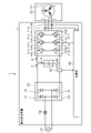
- FIG. 1 is a diagram showing a configuration example of the power conversion device 1 according to the first embodiment.
- the power converter 1 is connected to the commercial power supply 110 and the compressor 315.
- the power conversion device 1 converts the first AC power of the power supply voltage Vs supplied from the commercial power supply 110 into the second AC power having a desired amplitude and phase, and supplies the first AC power to the compressor 315.
- the power conversion device 1 includes a reactor 120, a rectifying unit 130, a current detecting unit 501, a smoothing unit 200, an inverter 310, current detecting units 313a and 313b, and a control unit 400.
- the motor drive device 2 is composed of the power converter 1 and the motor 314 included in the compressor 315.
- the reactor 120 is connected between the commercial power supply 110 and the rectifying unit 130.
- the rectifying unit 130 has a bridge circuit composed of rectifying elements 131 to 134, and rectifies and outputs the first AC power of the power supply voltage Vs supplied from the commercial power supply 110.
- the rectifying unit 130 performs full-wave rectification.
- the current detection unit 501 detects the current rectified by the rectifying unit 130 and flows into the smoothing unit 200 from the rectifying unit 130, that is, the input current to the smoothing unit 200, and outputs the detected current value to the control unit 400.
- the current detection unit 501 is a detection unit that detects the power state of the capacitor 210.
- the smoothing unit 200 is connected to the output end of the rectifying unit 130.
- the smoothing unit 200 has a capacitor 210 as a smoothing element, and smoothes the electric power rectified by the rectifying unit 130.
- the capacitor 210 is, for example, an electrolytic capacitor, a film capacitor, or the like.
- the capacitor 210 is connected to the output end of the rectifying unit 130 and has a capacity for smoothing the power rectified by the rectifying unit 130, and the voltage generated in the capacitor 210 by the smoothing is full-wave rectification of the commercial power supply 110. It is not a waveform shape, but a waveform shape in which a voltage ripple corresponding to the frequency of the commercial power supply 110 is superimposed on a DC component, and does not pulsate significantly.
- the frequency of this voltage ripple is twice the frequency of the power supply voltage Vs when the commercial power supply 110 is single-phase, and is mainly composed of six times the frequency when the commercial power supply 110 is three-phase.
- the amplitude of this voltage ripple is determined by the capacity of the capacitor 210.
- the voltage ripple generated in the capacitor 210 is pulsating in a range where the maximum value is less than twice the minimum value.
- the inverter 310 is connected to the smoothing portion 200, that is, both ends of the capacitor 210.
- the inverter 310 has switching elements 311a to 311f and freewheeling diodes 312a to 312f.
- the inverter 310 turns on and off the switching elements 311a to 311f under the control of the control unit 400, and converts the power output from the rectifying unit 130 and the smoothing unit 200 into a second AC power having a desired amplitude and phase, that is, a second AC power.
- AC power is generated and output to the compressor 315.
- the current detection units 313a and 313b each detect the current value of one of the three-phase currents output from the inverter 310, and output the detected current value to the control unit 400.
- the control unit 400 can calculate the current value of the remaining one phase output from the inverter 310 by acquiring the current value of two phases out of the current values of the three phases output from the inverter 310. ..
- the compressor 315 is a load having a motor 314 for driving the compressor.
- the motor 314 rotates according to the amplitude and phase of the second AC power supplied from the inverter 310, and performs a compression operation.
- the load torque of the compressor 315 can often be regarded as a constant torque load.
- FIG. 1 shows a case where the motor winding is Y-connected, but this is an example and is not limited thereto.
- the motor winding of the motor 314 may have a ⁇ connection or a specification in which the Y connection and the ⁇ connection can be switched.
- the arrangement of each configuration shown in FIG. 1 is an example, and the arrangement of each configuration is not limited to the example shown in FIG.
- the reactor 120 may be arranged after the rectifying unit 130.
- the power conversion device 1 may be provided with a boosting unit, or the rectifying unit 130 may be provided with the function of a boosting unit.
- the current detection unit 501 and the current detection units 313a and 313b may be collectively referred to as a detection unit.
- the current value detected by the current detection unit 501 and the current value detected by the current detection units 313a and 313b may be referred to as a detection value.
- the control unit 400 acquires the current value of the input current of the smoothing unit 200 from the current detection unit 501, and the current of the second AC power having a desired amplitude and phase converted from the current detection units 313a and 313b by the inverter 310. Get the value.
- the control unit 400 controls the operation of the inverter 310, specifically, the on / off of the switching elements 311a to 311f of the inverter 310 by using the detection value detected by each detection unit.
- the control unit 400 outputs a second AC power including a pulsation corresponding to the pulsation of the electric power flowing from the rectifying unit 130 to the capacitor 210 of the smoothing unit 200 from the inverter 310 to the compressor 315 which is a load.
- the operation of the inverter 310 is controlled so as to be performed.
- the pulsation according to the pulsation of the electric power flowing into the capacitor 210 of the smoothing portion 200 is, for example, a pulsation that fluctuates depending on the frequency of the pulsation of the electric power flowing into the capacitor 210 of the smoothing portion 200.
- the control unit 400 suppresses the current flowing through the capacitor 210 of the smoothing unit 200.
- the control unit 400 does not have to use all the detected values acquired from each detection unit, and may perform control using some of the detected values.
- the control unit 400 controls so that any one of the speed, voltage, and current of the motor 314 is in a desired state.
- the motor 314 is used for driving the compressor 315 and the compressor 315 is a closed type compressor, it is structurally and cost-wise to attach a position sensor for detecting the rotor position to the motor 314. Since it is difficult, the control unit 400 controls the motor 314 without a position sensor.
- a sensorless vector control will be described as a base. The control method described below can also be applied to the constant primary magnetic flux control with minor changes.
- the input current from the rectifying unit 130 to the capacitor 210 of the smoothing unit 200 is the input current I1
- the output current from the capacitor 210 of the smoothing unit 200 to the inverter 310 is the output current I2.
- the charge / discharge current of the capacitor 210 of the smoothing portion 200 be the charge / discharge current I3.
- the input current I1 is affected by the power supply phase of the commercial power supply 110, the characteristics of the elements installed before and after the rectifying unit 130, and the like, it basically has a characteristic of including a component 2n times the power supply frequency. Note that n is an integer of 1 or more.
- the ripple component caused by PWM Pulse Width Modulation
- the control unit 400 needs to control the inverter 310 in consideration of the ripple component.
- the control unit 400 monitors the power state of the smoothing unit 200, that is, the capacitor 210, and gives an appropriate pulsation to the motor 314 so that the charge / discharge current I3 decreases. good.
- the power state of the capacitor 210 is an input current I1 to the capacitor 210, an output current I2 from the capacitor 210, a charge / discharge current I3 of the capacitor 210, a DC bus voltage Vdc of the capacitor 210, and the like.
- the control unit 400 needs information on at least one of the power states of these capacitors 210 for deterioration suppression control.
- the control unit 400 uses the input current I1 to the capacitor 210 detected by the current detection unit 501 so that the value obtained by removing the PWM ripple from the output current I2 matches the input current I1. Add pulsation to 314. That is, the control unit 400 controls the operation of the inverter 310 so that the pulsation according to the detection value of the current detection unit 501 is superimposed on the drive pattern of the motor 314, and suppresses the charge / discharge current I3 of the capacitor 210.
- the control unit 400 controls the q-axis current command i q * of the motor 314 from the relationship between the input / output power of the motor 314 so that the difference between the input current I1 and the output current I2 becomes small.
- the control unit 400 calculates an ideal q-axis current for reducing the charge / discharge current I3 by utilizing the relationship between the input power to the inverter 310 and the mechanical output of the motor 314.
- This control method requires a sensor that detects the input current I1, that is, a current detection unit 501, but since the pulsating waveform of the q-axis current is directly determined using a theoretical formula, it is responsive to changes in the input current I1.
- the control unit 400 controls in the rotating coordinate system having the d-axis and the q-axis.
- the current detection unit 501 detects the current value of the input current I1 to the capacitor 210 and outputs the current value to the control unit 400.
- the control unit 400 controls the inverter 310 so that the value obtained by removing the PWM ripple from the output current I2 from the capacitor 210 to the inverter 310 matches the input current I1, and adds pulsation to the power output to the motor 314.
- the control unit 400 can reduce the charge / discharge current I3 of the capacitor 210 by appropriately pulsating the output current I2.
- the output current I2 and the q-axis current of the motor 314 also contain a component 2n times the power supply frequency. ..
- the AC power supply voltage from the commercial power supply 110 which is the input to the power conversion device 1, is represented by the equation (1).
- V s indicates the amplitude of the AC power supply voltage
- ⁇ in indicates the angular frequency of the AC power supply voltage
- t indicates the time.
- the input current I1 to the capacitor 210 includes a PWM ripple, but it should not be averaged and considered. And.
- the input current I1 is a periodic function
- the input current I1 can be expressed by the equation (2).
- the input current I1 has a waveform that includes many components that are integral multiples of the power supply frequency 2f due to the rectifying unit 130.
- the fundamental wave of the input current I1 is a component of the power supply frequency 2f.
- the "1" part of the input current I1 is subscripted in order to match the notation with the others. The same shall apply thereafter.
- I DC indicates the direct current component of the current, I 2f , I 4f , I 6f , ... Indicates the fundamental and harmonic amplitudes of the current, and ⁇ 2f , ⁇ 4f , ⁇ 6f , ... Shows the fundamental phase and harmonic phase.
- the input current I1 may be used as it is for the control of the control unit 400, or the input current I1 may be filtered and then used for the control of the control unit 400.
- the input current I1 ′ is obtained by extracting the DC component, the fundamental wave component, and the low-order harmonic component of the input current I1 by a low-pass filter and a band-pass filter
- the input current I1 ′ is expressed by, for example, the equation (3).
- the input current I1' is obtained by extracting the DC component, the power supply frequency 2f component, and the power supply frequency 4f component, but a component having a power supply frequency of 6f or more may be added.
- the bandpass filter may be configured by an FIR (Fiinite Impulse Response) filter or an IIR (Infinite Impulse Response) filter. Further, the input current I1'may be calculated from the coefficient calculation formula of the Fourier series expansion.
- the reason why only a specific frequency component is extracted by the above-mentioned filters is to prevent an unintended frequency component from being included in the pulsation given to the motor 314.
- the responsiveness to the change of the input current I1 is lowered, so whether or not to use the filters may be decided depending on the situation. In the following description, it is assumed that the above-mentioned filters are used.
- the output current command I 2 * of the output current I 2 from the capacitor 210 is given as in the equation (4).
- V dc represents the DC bus voltage.
- the active power P mot consumed by the motor 314 is expressed by the dq-axis voltage and the dq-axis current as shown in the equation (6).
- Ra indicates the armature resistance
- L d and L q indicate the dq axis inductance
- ⁇ a indicates the number of dq axis interlinkage magnetic fluxes
- ⁇ e indicates the electric angular velocity.
- the q-axis current pulsation command i qrip * is given as in the equation (9), it is possible to suppress the deterioration of the capacitor 210 of the smoothing portion 200.
- the calculation may be performed as in the equation (10) in consideration of the reluctance torque.
- id * is a d -axis current command.
- P mot Pin is assumed, but the motor 314 is accompanied by losses such as copper loss, iron loss, and mechanical loss. Therefore, the calculation may be performed in consideration of such a loss.
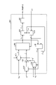
- FIG. 2 is a block diagram showing a configuration example of the control unit 400 included in the power conversion device 1 according to the first embodiment.
- the control unit 400 includes a rotor position estimation unit 401, a speed control unit 402, a weakening magnetic flux control unit 403, a current control unit 404, a coordinate conversion unit 405, 406, a PWM signal generation unit 407, and a q-axis current.
- a pulsation calculation unit 408 and an addition unit 409 are provided.
- the rotor position estimation unit 401 is the direction of the rotor magnetic pole on the dq axis with respect to the rotor (not shown) of the motor 314 from the dq axis voltage command vector V dq * and the dq axis current vector i dq applied to the motor 314.
- the estimated phase angle ⁇ est and the estimated speed ⁇ est are estimated.
- the speed control unit 402 automatically adjusts the q-axis current command i q * so that the speed command ⁇ * and the estimated speed ⁇ est match.
- the speed command ⁇ * is set when the power conversion device 1 is used as an air conditioner or the like as a refrigeration cycle application device, for example, the temperature detected by a temperature sensor (not shown) or a setting instructed by a remote controller which is an operation unit (not shown). It is based on information indicating the temperature, operation mode selection information, operation start and operation end instruction information, and the like.
- the operation mode is, for example, heating, cooling, dehumidification, and the like.
- the weakening magnetic flux control unit 403 automatically adjusts the d -axis current command id * so that the absolute value of the dq-axis voltage command vector V dq * falls within the limit value of the voltage limit value V lim * . Further, in the present embodiment, the weakening magnetic flux control unit 403 performs the weakening magnetic flux control in consideration of the q-axis current pulsation command i qrip * calculated by the q-axis current pulsation calculation unit 408.
- Weak magnetic flux control is roughly divided into a method of calculating the d -axis current command id * from the equation of the voltage limiting ellipse, and the deviation of the absolute value between the voltage limit value V lim * and the dq-axis voltage command vector V dq * is zero.
- the current control unit 404 automatically adjusts the dq-axis voltage command vector V dq * so that the dq-axis current vector i dq follows the d -axis current command id * and the q-axis current command i q * .
- the coordinate conversion unit 405 converts the dq axis voltage command vector V dq * from the dq coordinates to the voltage command V uvw * of the AC amount according to the estimated phase angle ⁇ est .
- the coordinate conversion unit 406 converts the current I uvw flowing through the motor 314 from the alternating current amount into the dq-axis current vector i dq of the dq coordinates according to the estimated phase angle ⁇ est .
- the control unit 400 has the current values of the two phases detected by the current detection units 313a and 313b among the three-phase current values output from the inverter 310 with respect to the current Ivw flowing through the motor 314. It can be obtained by calculating the current value of the remaining one phase using the current value of the two phases.
- the PWM signal generation unit 407 generates a PWM signal based on the voltage command V uvw * coordinate-converted by the coordinate conversion unit 405.
- the control unit 400 applies a voltage to the motor 314 by outputting the PWM signal generated by the PWM signal generation unit 407 to the switching elements 311a to 311f of the inverter 310.
- the q-axis current pulsation calculation unit 408 uses the above-mentioned q-axis current pulsation command i qrip * based on the input current I1, the DC bus voltage V dc , and the estimated speed ⁇ est , which are the current values detected by the current detection unit 501. Is calculated.
- the power conversion device 1 generally includes a detection unit that detects the DC bus voltage Vdc of the capacitor 210 for circuit protection, control reasons, and the like.
- the addition unit 409 adds and adds the q-axis current command i q * output from the speed control unit 402 and the q-axis current pulsation command i qrip * calculated by the q-axis current pulsation calculation unit 408. It is output as a q-axis current command i q * to the current control unit 404.
- the control unit 400 calculates the q-axis current pulsation command i qrip * based on the equation (9) or the equation (10) as compared with the power conversion device that performs the same control as the conventional one, and the q-axis current pulsation command i.
- the difference is that the q-axis current command i q * is calculated using qrip * and the weakening magnetic flux control is performed by adding the q-axis current pulsation command i qrip * .
- Applications such as compressor motors for air conditioning actively utilize weakened magnetic flux control, inverter overmodulation, etc., but in the voltage saturation range where these controls are used, even if pulsation is applied only to the q-axis current, the voltage is insufficient.
- the weakening magnetic flux control unit 403 pulsates the d -axis current id at the same time as the q-axis current pulsation command i qrip * at the time of voltage saturation to prevent the voltage from becoming insufficient.
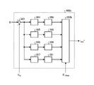
- FIG. 3 is a diagram showing a configuration example of the q-axis current pulsation calculation unit 408 of the control unit 400 included in the power conversion device 1 according to the first embodiment.
- the q-axis current pulsation calculation unit 408 includes a filter 381 and an amplitude conversion unit 382.
- the filter 381 passes the input current I1 to the capacitor 210 and calculates the output current command I 2 * from the capacitor 210.
- the filter 381 has been described as a combination of a low-pass filter and a band-pass filter, but this configuration is an example, and another type of filter may be used. Further, when the q-axis current pulsation calculation unit 408 places more importance on responsiveness, the filter 381 may be omitted.
- the amplitude conversion unit 382 performs the calculation of equation (9) or equation (10) using the output current command I 2 * from the capacitor 210, the DC bus voltage V dc , and the estimated speed ⁇ est of the motor 314. Calculate the shaft current pulsation command i qrip * . Since the pulsating amplitude of the q-axis current changes depending on the driving conditions of the motor 314, the amplitude conversion unit 382 determines the amplitude in consideration of the driving conditions appropriately.
- the control unit 400 appropriately applies pulsation to the motor 314 by the q-axis current pulsation calculation unit 408, and controls the current flowing through the capacitor 210 to be close to zero or to a small value, so that the current flows into and out of the capacitor 210. That is, the charge / discharge current I3 of the capacitor 210 can be reduced.
- FIG. 4 is a diagram showing an example of a drive waveform in a power conversion device having the same circuit configuration as the power conversion device 1 of the first embodiment as a comparative example. It is assumed that the power conversion device of the comparative example, which is the object of FIG. 4, is not controlled like the power conversion device 1 of the present embodiment.
- FIG. 5 is a diagram showing an example of a drive waveform in the power conversion device 1 according to the first embodiment.
- the upper figure shows the input current I1 from the rectifying unit 130 to the capacitor 210, the output current I2 from the capacitor 210, and the charge / discharge current I3 of the capacitor 210, and the lower figure shows the DC bus voltage Vdc .
- FIGS. 4 and 5 are drawn on the same scale. Further, for convenience of explanation, PWM ripple is not considered in FIGS. 4 and 5.
- the input current I1 flowing into the capacitor 210 has a shape like a “rabbit ear”.
- the charge / discharge current I3 of the capacitor also has the shape of a “rabbit ear”.
- a large ripple occurs in the DC bus voltage Vdc . Since these waveforms have a large periodic pulsation, the deterioration of the capacitor 210 over time is accelerated.
- the control unit 400 controls the operation of the inverter 310 so that the output current I2 from the capacitor 210 is in the shape of a “rabbit ear”, so that the capacitor 210 The peak value of the charge / discharge current I3 becomes smaller. At the same time that the peak value of the charge / discharge current I3 of the capacitor 210 becomes small, the ripple of the DC bus voltage Vdc also becomes small. By reducing the outflow and inflow of the current of the capacitor 210, the deterioration of the element can be suppressed and the aging deterioration of the component can be suppressed.
- the capacity of the element can be reduced by the amount of suppression of the control unit 400 as described above, and the ripple withstand capacity is relaxed. Therefore, an inexpensive smoothing element, that is, a capacitor 210 can be utilized, and the system cost can be suppressed.
- a capacitor 210 In FIG. 5, only the DC component, the power supply frequency 2f component, and the power supply frequency 4f component are extracted to perform deterioration suppression control, but when it is desired to make the charge / discharge current I3 of the capacitor 210 smaller, the order is higher. Ingredients may be added. However, in practice, it is considered necessary and sufficient if the power frequency up to the 6f component is taken into consideration. Further, when it is desired to reduce the amount of calculation, only the DC component and the power supply frequency 2f component may be considered.
- the control method of the control unit 400 is based on the theoretical formula of the input / output power of the motor 314, the q-axis current pulsation of the motor 314 can be directly determined with respect to the change of the input current I1. Highly responsive to changes in the input current I1. Therefore, there is an advantage that deterioration of the capacitor 210 of the smoothing portion 200 can be easily suppressed when used in combination with pulsation load compensation.
- the control method of the first embodiment has a difficulty in robustness as compared with the control method based on the automatic search of the second embodiment and the third embodiment described later. It is clear from Eqs. (9), Eq. (10), etc. that the desired control becomes difficult when the constant fluctuation occurs.
- the control unit 400 in addition to the above-mentioned control, speed pulsation caused by the load torque pulsation. It may be controlled so as to suppress.
- FIG. 6 is a flowchart showing the operation of the control unit 400 included in the power conversion device 1 according to the first embodiment.
- the control unit 400 acquires the input current I1 of the capacitor 210, which is a detected value, from the current detection unit 501 (step S1).
- the control unit 400 controls the operation of the inverter 310 based on the acquired detection value so that the difference between the input current I1 to the capacitor 210 and the output current I2 from the capacitor 210 becomes small (step S2).
- FIG. 7 is a diagram showing an example of a hardware configuration that realizes the control unit 400 included in the power conversion device 1 according to the first embodiment.
- the control unit 400 is realized by the processor 91 and the memory 92.
- the processor 91 is a CPU (Central Processing Unit, central processing unit, processing unit, arithmetic unit, microprocessor, microprocessor, processor, DSP (Digital Signal Processor)), or system LSI (Large Scale Integration).
- the memory 92 is a RAM (Random Access Memory), a ROM (Read Only Memory), a flash memory, an EPROM (Erasable Programmable Read Only Memory), an EPROM (registered trademark) (Electrically Memory)
- a semiconductor memory can be exemplified. Further, the memory 92 is not limited to these, and may be a magnetic disk, an optical disk, a compact disk, a mini disk, or a DVD (Digital Versaille Disc).
- the control unit 400 uses the input current I1 to the capacitor 210 detected by the current detection unit 501 to generate the q-axis current pulsation command i. It was decided to calculate qrip * and generate d -axis current command id * using the q-axis current pulsation command i qrip * to control the operation of the inverter 310 and suppress the charge / discharge current I3 of the capacitor 210. As a result, the power conversion device 1 can suppress the deterioration of the smoothing capacitor 210 while suppressing the increase in size of the power conversion device 1.
- Embodiment 2 in the power conversion device, the motor 314 that detects the charge / discharge current I3 flowing through the capacitor 210 and reduces the peak value of the charge / discharge current I3 or a specific frequency component contained in the charge / discharge current I3.
- the drive pattern including the pulsation of the electric current is automatically searched.
- the famous automatic search method is, for example, the mountain climbing method, but any method may be used as long as it is an automatic search method.
- feedback control is also considered to be a kind of automatic search method, so the feedback control technique may be used.
- the control method of the second embodiment requires a sensor for detecting the charge / discharge current I3, which is difficult in terms of cost.
- it is robust even when the constant fluctuation of the motor 314 occurs. It is possible to suppress deterioration.
- the control that minimizes the charge / discharge current I3 by utilizing the feedback control will be described.
- the control method described here automatically searches for a drive pattern including the pulsation of the motor 314 that minimizes the charge / discharge current I3.
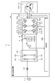
- FIG. 8 is a diagram showing a configuration example of the power conversion device 1a according to the second embodiment.
- the power conversion device 1a is the power conversion device 1 of the first embodiment shown in FIG. 1, in which the control unit 400 and the current detection unit 501 are deleted, and the control unit 400a and the current detection unit 502 are added. be.
- the motor drive device 2a is composed of the power conversion device 1a and the motor 314 included in the compressor 315.
- the current detection unit 502 detects the charge / discharge current I3 of the capacitor 210 and outputs the detected current value to the control unit 400a.
- the current detection unit 502 is a detection unit that detects the power state of the capacitor 210.
- control unit 400a is obtained by deleting the q-axis current pulsation calculation unit 408 and adding the q-axis current pulsation calculation unit 408a to the control unit 400 of the first embodiment shown in FIG.
- FIG. 10 is a diagram showing a configuration example of the q-axis current pulsation calculation unit 408a of the control unit 400a included in the power conversion device 1a according to the second embodiment.
- the q-axis current pulsation calculation unit 408a is configured as a feedback controller with the command value set to zero. Normally, the feedback controller has a lower control response than the feedforward controller and is not suitable for suppressing high frequency pulsation, but various high frequency pulsation suppressing means have been proposed in the past.
- As a well-known method there is a method using a Fourier coefficient calculation and a PID (Proportional Integral Differential) controller.
- the q-axis current pulsation calculation unit 408a includes a subtraction unit 383, a Fourier coefficient calculation unit 384 to 387, a PID control unit 388 to 391, and an AC restoration unit 392.
- the Fourier coefficient calculation units 384 to 387 calculate the amplitudes of the sin2f component, the cos2f component, the sin4f component, and the cos4f component included in the deviation, assuming that the power frequency is the 1f component.
- the detection signals multiplied by the Fourier coefficient calculation units 384 to 387 are sin2 ⁇ int , cos2 ⁇ int , sin4 ⁇ int , and cos4 ⁇ int , respectively, and the deviation includes twice the average value of the product of the input signal and the detection signal, respectively. It is the amplitude of the sin2f component, the cos2f component, the sin4f component, and the cos4f component. That is, the Fourier coefficient calculation units 384 to 387 calculate the amplitude of the component corresponding to the power supply frequency of the commercial power supply 110 included in the deviation between the detected value and the command value. If the charge / discharge current I3 of the capacitor 210 is a periodic waveform, the output signals of the Fourier coefficient calculation units 384 to 387 are substantially constant.
- the PID control units 388 to 391 carry out proportional-integral-differential control, that is, PID control so that the specific frequency components of these deviations become zero.
- the proportional gain and derivative gain can be zero, but the integrated gain value must be non-zero in order for the deviation to converge to zero. Therefore, in the PID control units 388 to 391, the integration operation is the main operation. Normally, since the output of the integral control changes slowly, the output of the PID control units 388 to 391 can also be regarded as being substantially constant.
- the AC restoration unit 392 multiplies the outputs of the PID control units 388 to 391 with sin2 ⁇ int , cos2 ⁇ int , sin4 ⁇ int , and cos4 ⁇ int , respectively, and then adds them up to restore the q-axis current pulsation command i qrip. * Determine. That is, the AC restoration unit 392 generates the q-axis current pulsation command i qrip * , which is a command for the pulsation for suppressing the charge / discharge current I3 of the capacitor 210.
- the problem of robustness which is a drawback of the control method of the first embodiment, is improved.
- the control response cannot be increased because the PID control is mainly used for the integral operation.
- a sensor for detecting the charge / discharge current I3, that is, a current detection unit 502 is required, there is a problem in terms of cost.
- the control methods of each embodiment may be freely combined and used, including the control method of the third embodiment described later.
- the case where the sensorless vector control method is used has been illustrated, but it can also be applied to the constant primary magnetic flux control by adding a pulsation to the speed command, the voltage command, etc. by adding some deformation. ..
- an appropriate phase offset may be given to the trigonometric function for AC restoration to be multiplied.
- the motor 314 is a permanent magnet synchronous motor
- the current vector and the voltage vector in the steady state have a phase difference of about several tens of degrees. If it is added to the command, the same control is possible even with constant primary magnetic flux control.
- FIG. 11 is a flowchart showing the operation of the control unit 400a included in the power conversion device 1a according to the second embodiment.
- the control unit 400a acquires the charge / discharge current I3 of the capacitor 210, which is a detected value, from the current detection unit 502 (step S11).
- the control unit 400a controls the operation of the inverter 310 so that the specific frequency component included in the charge / discharge current I3 of the capacitor 210 is reduced based on the acquired detected value (step S12).
- the control unit 400a determines the drive pattern of the motor 314 in which the pulsation component of a specific frequency included in the charge / discharge current I3 of the capacitor 210 is reduced. It was decided to suppress the charge / discharge current I3 of the capacitor 210 by automatically searching and controlling the operation of the inverter 310. As a result, the power conversion device 1a can suppress the deterioration of the smoothing capacitor 210 and the increase in size of the power conversion device 1a.
- Embodiment 3 in the power conversion device, the DC bus voltage V dc , which is the voltage across the capacitor 210, is detected, and the drive pattern including the pulsation of the motor 314 such that the pulsation width of the DC bus voltage V dc is reduced is automatically performed.
- the DC bus voltage V dc which is the voltage across the capacitor 210
- the power conversion device generally detects the DC bus voltage Vdc of the capacitor 210 by the voltage detection unit. Therefore, the control method of the third embodiment is the embodiment. Unlike the control method of 1 and 2, it is not necessary to add a current detection unit. The control method of the third embodiment is superior in terms of cost as compared with the control method of the first embodiment and the second embodiment.
- any method may be used as long as it is an automatic search method.
- feedback control is also considered to be a kind of automatic search method, so the feedback control technique may be used.
- the control method based on the automatic search can robustly suppress deterioration even when the constant fluctuation of the motor 314 occurs.
- the control for reducing the pulsation width of the DC bus voltage Vdc using the feedback control will be described.
- the control method described here automatically searches for a drive pattern including the pulsation of the motor 314 in which the pulsation width of the DC bus voltage Vdc decreases.
- FIG. 12 is a diagram showing a configuration example of the power conversion device 1b according to the third embodiment.
- the power conversion device 1b is the power conversion device 1 of the first embodiment shown in FIG. 1, in which the control unit 400 and the current detection unit 501 are deleted, and the control unit 400b and the voltage detection unit 503 are added. be.
- the motor drive device 2b is composed of the power conversion device 1b and the motor 314 included in the compressor 315.
- the voltage detection unit 503 detects the DC bus voltage Vdc , which is the voltage across the capacitor 210, and outputs the detected voltage value to the control unit 400b.
- the voltage detection unit 503 is a detection unit that detects the power state of the capacitor 210.
- the power conversion device generally detects the DC bus voltage V dc of the capacitor 210 for reasons of circuit protection, control, and the like. It has a configuration, that is, a detection unit corresponding to the voltage detection unit 503 of the present embodiment.
- FIG. 13 is a block diagram showing a configuration example of the control unit 400b included in the power conversion device 1b according to the third embodiment.
- the control unit 400b deletes the q-axis current pulsation calculation unit 408 and adds the q-axis current pulsation calculation unit 408b to the control unit 400 of the first embodiment shown in FIG. In the q-axis current pulsation calculation unit 408a of the second embodiment shown in FIG.
- FIG. 14 is a diagram showing a configuration example of the q-axis current pulsation calculation unit 408b of the control unit 400b included in the power conversion device 1b according to the third embodiment.
- the q-axis current pulsation calculation unit 408b is configured as a feedback controller with a target value of zero.
- the q-axis current pulsation calculation unit 408b includes a subtraction unit 383, a Fourier coefficient calculation unit 384 to 387, a PID control unit 388 to 391, and an AC restoration unit 392b.
- the Fourier coefficient calculation units 384 to 387 calculate the amplitudes of the sin2f component, the cos2f component, the sin4f component, and the cos4f component included in the deviation, assuming that the power frequency is the 1f component. That is, the Fourier coefficient calculation units 384 to 387 calculate the amplitude of the component corresponding to the power supply frequency of the commercial power supply 110 included in the deviation between the detected value and the target value.
- the PID control units 388 to 391 carry out proportional-integral-differential control, that is, PID control so that the specific frequency components of these deviations become zero.
- the proportional gain and derivative gain can be zero, but the integrated gain value must be non-zero in order for the deviation to converge to zero. Therefore, in the PID control units 388 to 391, the integration operation is the main operation. Normally, since the output of the integral control changes slowly, the output of the PID control units 388 to 391 can also be regarded as being substantially constant. Regarding the Fourier coefficient calculation units 384 to 387 and the PID control units 388 to 391, the calculation contents are almost the same as those in the second embodiment except that the input values are different.
- the AC restoration unit 392b integrates the charge / discharge current I3 of the capacitor 210.
- the AC restoration unit 392b must determine the q-axis current pulsation command i qrip * in consideration of the phase difference of 90 degrees.
- the AC restoration unit 392b performs the restoration operation as follows. In this way, the AC restoration unit 392b generates the q-axis current pulsation command i qrip * , which is a command for the pulsation for suppressing the charge / discharge current I3 of the capacitor 210.
- the restoration signals in the AC restoration unit 392b are sin2 ( ⁇ int + ⁇ offset ) and cos2. ( ⁇ int + ⁇ offset ), sin4 ( ⁇ int + ⁇ offset ), and cos4 ( ⁇ int + ⁇ offset ).
- the q-axis current pulsation calculation unit 408a of the second embodiment shown in FIG. 10 may use the same detection signal and restoration signal, but the q-axis current pulsation calculation unit 408b of the third embodiment shown in FIG. 14 may use the same detection signal and restoration signal.
- the AC restoration unit 392b can determine the q-axis current pulsation command i qrip * by calculating the sum of products of the outputs of the PID control units 388 to 391 and the restoration signal.
- the control method of each embodiment by using such a control method, it is advantageous in terms of cost as compared with the first embodiment and the second embodiment. Further, in the third embodiment, by using such a control method, the problem of robustness, which is a drawback of the control method of the first embodiment, is improved. On the other hand, the control response cannot be increased because the PID control is mainly used for the integral operation. As described above, in order to compensate for the weaknesses of the control methods of each embodiment, the control methods of each embodiment may be freely combined and used, including the control method of the fourth embodiment described later.
- FIG. 15 is a flowchart showing the operation of the control unit 400b included in the power conversion device 1b according to the third embodiment.
- the control unit 400b acquires the DC bus voltage V dc , which is the voltage across the capacitor 210, which is the detected value, from the voltage detection unit 503 (step S21).
- the control unit 400b controls the operation of the inverter 310 so that the specific pulsation width included in the DC bus voltage Vdc is reduced based on the acquired detected value (step S22).
- the control unit 400b automatically searches for the drive pattern of the motor 314 in which the pulsation component of a specific frequency included in the DC bus voltage Vdc is reduced.
- the charge / discharge current I3 of the capacitor 210 is suppressed.
- the power conversion device 1b can suppress the deterioration of the smoothing capacitor 210 while suppressing the increase in size of the power conversion device 1b.
- Embodiment 4 a method of determining a drive pattern including a pulsation of the q-axis current in which the charge / discharge current I3 of the capacitor 210 decreases during driving of the motor 314 has been described. However, if the drive pattern including the pulsation of the q-axis current in which the charge / discharge current I3 of the capacitor 210 decreases is known, deterioration suppression control may be performed based on the known data.
- a method is conceivable in which a pulsation pattern representing the pulsation of the q-axis current in which the charge / discharge current I3 of the capacitor 210 decreases is investigated in advance, and deterioration suppression control is performed based on the pre-learned data.
- the pulsation pattern of the motor 314 in which the pulsation of the charge / discharge current I3 or the DC bus voltage Vdc is reduced is investigated in advance, and the pulsation is given to the motor 314 using the data investigated in advance.
- the data investigated in advance is stored in a storage unit in the power conversion device, and an appropriate pulsation pattern is selected according to the driving conditions of the motor 314.
- FIG. 16 is a block diagram showing a configuration example of the control unit 400c included in the power conversion device according to the fourth embodiment.
- the power conversion device including the control unit 400c may have the same circuit configuration as the power conversion devices 1 to 1b described in the first to third embodiments, or may be individually provided in each embodiment.
- the circuit configuration may not include the detection unit.
- the control unit 400c is obtained by deleting the q-axis current pulsation calculation unit 408 and adding the q-axis current pulsation calculation unit 408c to the control unit 400 of the first embodiment shown in FIG.
- the q-axis current pulsation calculation unit 408c includes a storage unit (not shown) and a pulsation pattern generation unit.
- the storage unit stores a pulsation pattern of the motor 314 in which the charge / discharge current I3 of the capacitor 210 is reduced.
- the pulsation pattern data stored in the storage unit was obtained by a preliminary survey.
- a certain pulsation pattern may be applied by trial and error to investigate a pattern in which the pulsation of the charge / discharge current I3 or the DC bus voltage Vdc decreases, or the investigation is performed using the above-mentioned automatic search method. It doesn't matter.
- the survey may be conducted through an actual machine test or a computer simulation. In recent years, machine learning and AI (Artificial Intelligence) techniques have become common, and such techniques may be used.
- AI Artificial Intelligence
- the control unit 400c automatically searches for a pulsation pattern in which the pulsation component of a specific frequency included in the charge / discharge current I3 detected by the current detection unit 502 decreases, and controls the control.
- the pulsation pattern obtained in the process may be stored as a pulsation pattern set for each operating condition.
- the control unit 400c automatically searches for a pulsation pattern in which the pulsation component of a specific frequency included in the DC bus voltage Vdc detected by the voltage detection unit 503 decreases.
- the pulsation pattern obtained in the control process may be stored as a pulsation pattern set for each operating condition.
- the pulsation pattern data stored in the storage unit is associated with the operating conditions of the motor 314.
- the suction pressure, the discharge pressure, the temperature of the refrigerant, the target value of the room temperature of the air conditioner, and the like of the compressor 315 correspond to the operating conditions.
- the q-axis current pulsation calculation unit 408c selects an appropriate pulsation pattern from the storage unit for reducing the charge / discharge current I3 of the capacitor 210 according to such operating conditions.
- the q-axis current pulsation calculation unit 408c uses the pulsation pattern generation unit to generate the q-axis current pulsation command i qrip * based on the pulsation pattern selected from the storage unit.
- the q-axis current pulsation calculation unit 408c performs deterioration suppression control of the capacitor 210 by such control.
- control method based on the preliminary survey has the disadvantages of having difficulty in robustness and requiring a storage unit having a large capacity, but the calculation process itself is simple. Therefore, when the calculation performance of the computer is poor and the number of operating conditions is very small, the control method as in the fourth embodiment may be an effective means. In order to reduce the complexity of the preliminary survey, the control methods described in the first to fourth embodiments may be freely combined.
- FIG. 17 is a flowchart showing the operation of the control unit 400c included in the power conversion device according to the fourth embodiment.
- the control unit 400c acquires the operating conditions of the compressor 315 (step S31).
- the control unit 400c selects an appropriate pulsation pattern for reducing the charge / discharge current I3 of the capacitor 210 based on the acquired operating conditions, and controls the operation of the inverter 310 (step S32).
- the control unit 400c stores the pulsation pattern for suppressing the charge / discharge current I3 of the capacitor 210 set for each operating condition of the load including the motor 314.
- the q-axis current pulsation command i qrip * which is the command for the pulsation to suppress the charge / discharge current I3 of the capacitor 210, is generated, and the inverter 310 Control the operation. Also in this case, the same effects as those of the first to third embodiments can be obtained.
- FIG. 18 is a diagram showing a configuration example of the refrigeration cycle application device 900 according to the fifth embodiment.
- the refrigeration cycle application device 900 according to the fifth embodiment includes the power conversion device 1 described in the first embodiment.
- the refrigeration cycle application device 900 may include the power conversion devices 1a and 1b described in other embodiments, but here, as an example, a case where the power conversion device 1 is provided will be described.
- the refrigerating cycle applicable device 900 according to the fifth embodiment can be applied to products including a refrigerating cycle such as an air conditioner, a refrigerator, a freezer, and a heat pump water heater.
- the components having the same functions as those of the first embodiment are designated by the same reference numerals as those of the first embodiment.
- the compressor 315 having a built-in motor 314, the four-way valve 902, the indoor heat exchanger 906, the expansion valve 908, and the outdoor heat exchanger 910 form the refrigerant pipe 912 according to the first embodiment. It is attached via.
- a compression mechanism 904 for compressing the refrigerant and a motor 314 for operating the compression mechanism 904 are provided inside the compressor 315.
- the refrigeration cycle applicable device 900 can perform heating operation or cooling operation by switching operation of the four-way valve 902.
- the compression mechanism 904 is driven by a variable speed controlled motor 314.
- the refrigerant is pressurized by the compression mechanism 904 and sent out, and passes through the four-way valve 902, the indoor heat exchanger 906, the expansion valve 908, the outdoor heat exchanger 910 and the four-way valve 902. Return to the compression mechanism 904.
- the refrigerant is pressurized by the compression mechanism 904 and sent out, and passes through the four-way valve 902, the outdoor heat exchanger 910, the expansion valve 908, the indoor heat exchanger 906 and the four-way valve 902. Return to the compression mechanism 904.
- the indoor heat exchanger 906 acts as a condenser to release heat, and the outdoor heat exchanger 910 acts as an evaporator to absorb heat.
- the outdoor heat exchanger 910 acts as a condenser to release heat, and the indoor heat exchanger 906 acts as an evaporator to absorb heat.
- the expansion valve 908 depressurizes the refrigerant and expands it.
- the configuration shown in the above embodiments is an example, and can be combined with another known technique, can be combined with each other, and does not deviate from the gist. It is also possible to omit or change a part of the configuration.
Landscapes
- Engineering & Computer Science (AREA)
- Power Engineering (AREA)
- Control Of Ac Motors In General (AREA)
- Inverter Devices (AREA)
Priority Applications (2)
| Application Number | Priority Date | Filing Date | Title |
|---|---|---|---|
| JP2022573836A JP7499887B2 (ja) | 2021-01-06 | 2021-01-06 | 電力変換装置、モータ駆動装置および冷凍サイクル適用機器 |
| PCT/JP2021/000196 WO2022149210A1 (ja) | 2021-01-06 | 2021-01-06 | 電力変換装置、モータ駆動装置および冷凍サイクル適用機器 |
Applications Claiming Priority (1)
| Application Number | Priority Date | Filing Date | Title |
|---|---|---|---|
| PCT/JP2021/000196 WO2022149210A1 (ja) | 2021-01-06 | 2021-01-06 | 電力変換装置、モータ駆動装置および冷凍サイクル適用機器 |
Publications (1)
| Publication Number | Publication Date |
|---|---|
| WO2022149210A1 true WO2022149210A1 (ja) | 2022-07-14 |
Family
ID=82358097
Family Applications (1)
| Application Number | Title | Priority Date | Filing Date |
|---|---|---|---|
| PCT/JP2021/000196 Ceased WO2022149210A1 (ja) | 2021-01-06 | 2021-01-06 | 電力変換装置、モータ駆動装置および冷凍サイクル適用機器 |
Country Status (2)
| Country | Link |
|---|---|
| JP (1) | JP7499887B2 (https=) |
| WO (1) | WO2022149210A1 (https=) |
Cited By (1)
| Publication number | Priority date | Publication date | Assignee | Title |
|---|---|---|---|---|
| WO2024232029A1 (ja) * | 2023-05-10 | 2024-11-14 | 三菱電機株式会社 | 電力変換装置及びモータ駆動システム |
Citations (3)
| Publication number | Priority date | Publication date | Assignee | Title |
|---|---|---|---|---|
| JP2002354826A (ja) * | 2001-05-24 | 2002-12-06 | Isao Takahashi | インバータ制御方法およびその装置 |
| JP2009232591A (ja) * | 2008-03-24 | 2009-10-08 | Mitsubishi Electric Corp | 電動機駆動装置および空気調和機 |
| WO2018131273A1 (ja) * | 2017-01-11 | 2018-07-19 | 日立ジョンソンコントロールズ空調株式会社 | モータ駆動装置および冷凍機器 |
-
2021
- 2021-01-06 WO PCT/JP2021/000196 patent/WO2022149210A1/ja not_active Ceased
- 2021-01-06 JP JP2022573836A patent/JP7499887B2/ja active Active
Patent Citations (3)
| Publication number | Priority date | Publication date | Assignee | Title |
|---|---|---|---|---|
| JP2002354826A (ja) * | 2001-05-24 | 2002-12-06 | Isao Takahashi | インバータ制御方法およびその装置 |
| JP2009232591A (ja) * | 2008-03-24 | 2009-10-08 | Mitsubishi Electric Corp | 電動機駆動装置および空気調和機 |
| WO2018131273A1 (ja) * | 2017-01-11 | 2018-07-19 | 日立ジョンソンコントロールズ空調株式会社 | モータ駆動装置および冷凍機器 |
Cited By (1)
| Publication number | Priority date | Publication date | Assignee | Title |
|---|---|---|---|---|
| WO2024232029A1 (ja) * | 2023-05-10 | 2024-11-14 | 三菱電機株式会社 | 電力変換装置及びモータ駆動システム |
Also Published As
| Publication number | Publication date |
|---|---|
| JP7499887B2 (ja) | 2024-06-14 |
| JPWO2022149210A1 (https=) | 2022-07-14 |
Similar Documents
| Publication | Publication Date | Title |
|---|---|---|
| JP7466794B2 (ja) | 電力変換装置、モータ駆動装置および冷凍サイクル適用機器 | |
| CN118266161A (zh) | 电力转换装置、马达驱动装置以及制冷循环应用设备 | |
| WO2023073870A1 (ja) | 電力変換装置、モータ駆動装置および冷凍サイクル適用機器 | |
| WO2023105761A1 (ja) | 電力変換装置、電動機駆動装置及び冷凍サイクル適用機器 | |
| US20240405694A1 (en) | Power converting apparatus, motor drive unit, and refrigeration cycle-incorporating device | |
| WO2022149210A1 (ja) | 電力変換装置、モータ駆動装置および冷凍サイクル適用機器 | |
| US20240014759A1 (en) | Control device, power conversion apparatus, motor drive unit, and applied refrigeration cycle apparatus | |
| WO2023100359A1 (ja) | 電力変換装置、モータ駆動装置および冷凍サイクル適用機器 | |
| JP2019170119A (ja) | 冷凍サイクル装置 | |
| JP7330401B2 (ja) | 電力変換装置、モータ駆動装置および冷凍サイクル適用機器 | |
| WO2023100321A1 (ja) | 電力変換装置、モータ駆動装置及び冷凍サイクル適用機器 | |
| CN118104121A (zh) | 电力转换装置、马达驱动装置以及制冷循环应用设备 | |
| WO2023162106A1 (ja) | モータ駆動装置及び冷凍サイクル装置 | |
| JP7819347B2 (ja) | 電力変換装置、モータ駆動装置および冷凍サイクル適用機器 | |
| WO2023157045A1 (ja) | 電力変換装置および空気調和機 | |
| JP7325671B2 (ja) | 電力変換装置、モータ駆動装置および冷凍サイクル適用機器 | |
| CN118104122A (zh) | 电力转换装置、马达驱动装置以及制冷循环应用设备 | |
| JP7834200B2 (ja) | 電力変換装置、モータ駆動装置及び冷凍サイクル適用機器 | |
| KR102010388B1 (ko) | 모터 구동장치 및 이를 구비하는 공기조화기 | |
| US20250219560A1 (en) | Power conversion apparatus, motor drive apparatus, and refrigeration cycle application device | |
| US20250219553A1 (en) | Power converting apparatus, motor drive apparatus, and refrigeration-cycle application device | |
| CN118104123A (zh) | 电力转换装置、马达驱动装置以及制冷循环应用设备 | |
| WO2025203347A1 (ja) | 電力変換装置、モータ駆動装置及び冷凍サイクル適用機器 | |
| WO2025069182A1 (ja) | 電力変換装置、電動機駆動装置及び冷凍サイクル適用機器 | |
| WO2023067723A1 (ja) | 電力変換装置、電動機駆動装置及び冷凍サイクル適用機器 |
Legal Events
| Date | Code | Title | Description |
|---|---|---|---|
| 121 | Ep: the epo has been informed by wipo that ep was designated in this application |
Ref document number: 21917438 Country of ref document: EP Kind code of ref document: A1 |
|
| ENP | Entry into the national phase |
Ref document number: 2022573836 Country of ref document: JP Kind code of ref document: A |
|
| NENP | Non-entry into the national phase |
Ref country code: DE |
|
| 122 | Ep: pct application non-entry in european phase |
Ref document number: 21917438 Country of ref document: EP Kind code of ref document: A1 |