WO2022145284A1 - 医療器具の湾曲駒及び湾曲部並びに内視鏡 - Google Patents
医療器具の湾曲駒及び湾曲部並びに内視鏡 Download PDFInfo
- Publication number
- WO2022145284A1 WO2022145284A1 PCT/JP2021/047236 JP2021047236W WO2022145284A1 WO 2022145284 A1 WO2022145284 A1 WO 2022145284A1 JP 2021047236 W JP2021047236 W JP 2021047236W WO 2022145284 A1 WO2022145284 A1 WO 2022145284A1
- Authority
- WO
- WIPO (PCT)
- Prior art keywords
- curved
- piece
- peripheral wall
- medical device
- axial direction
- Prior art date
- Legal status (The legal status is an assumption and is not a legal conclusion. Google has not performed a legal analysis and makes no representation as to the accuracy of the status listed.)
- Ceased
Links
Images




Classifications
-
- A—HUMAN NECESSITIES
- A61—MEDICAL OR VETERINARY SCIENCE; HYGIENE
- A61B—DIAGNOSIS; SURGERY; IDENTIFICATION
- A61B1/00—Instruments for performing medical examinations of the interior of cavities or tubes of the body by visual or photographical inspection, e.g. endoscopes; Illuminating arrangements therefor
- A61B1/005—Flexible endoscopes
- A61B1/008—Articulations
-
- A—HUMAN NECESSITIES
- A61—MEDICAL OR VETERINARY SCIENCE; HYGIENE
- A61B—DIAGNOSIS; SURGERY; IDENTIFICATION
- A61B1/00—Instruments for performing medical examinations of the interior of cavities or tubes of the body by visual or photographical inspection, e.g. endoscopes; Illuminating arrangements therefor
- A61B1/005—Flexible endoscopes
- A61B1/0051—Flexible endoscopes with controlled bending of insertion part
- A61B1/0055—Constructional details of insertion parts, e.g. vertebral elements
-
- A—HUMAN NECESSITIES
- A61—MEDICAL OR VETERINARY SCIENCE; HYGIENE
- A61B—DIAGNOSIS; SURGERY; IDENTIFICATION
- A61B1/00—Instruments for performing medical examinations of the interior of cavities or tubes of the body by visual or photographical inspection, e.g. endoscopes; Illuminating arrangements therefor
- A61B1/00064—Constructional details of the endoscope body
- A61B1/00071—Insertion part of the endoscope body
- A61B1/0008—Insertion part of the endoscope body characterised by distal tip features
- A61B1/00098—Deflecting means for inserted tools
-
- A—HUMAN NECESSITIES
- A61—MEDICAL OR VETERINARY SCIENCE; HYGIENE
- A61B—DIAGNOSIS; SURGERY; IDENTIFICATION
- A61B1/00—Instruments for performing medical examinations of the interior of cavities or tubes of the body by visual or photographical inspection, e.g. endoscopes; Illuminating arrangements therefor
- A61B1/00131—Accessories for endoscopes
-
- G—PHYSICS
- G02—OPTICS
- G02B—OPTICAL ELEMENTS, SYSTEMS OR APPARATUS
- G02B23/00—Telescopes, e.g. binoculars; Periscopes; Instruments for viewing the inside of hollow bodies; Viewfinders; Optical aiming or sighting devices
- G02B23/24—Instruments or systems for viewing the inside of hollow bodies, e.g. fibrescopes
-
- G—PHYSICS
- G02—OPTICS
- G02B—OPTICAL ELEMENTS, SYSTEMS OR APPARATUS
- G02B23/00—Telescopes, e.g. binoculars; Periscopes; Instruments for viewing the inside of hollow bodies; Viewfinders; Optical aiming or sighting devices
- G02B23/24—Instruments or systems for viewing the inside of hollow bodies, e.g. fibrescopes
- G02B23/2476—Non-optical details, e.g. housings, mountings, supports
-
- A—HUMAN NECESSITIES
- A61—MEDICAL OR VETERINARY SCIENCE; HYGIENE
- A61B—DIAGNOSIS; SURGERY; IDENTIFICATION
- A61B1/00—Instruments for performing medical examinations of the interior of cavities or tubes of the body by visual or photographical inspection, e.g. endoscopes; Illuminating arrangements therefor
- A61B1/005—Flexible endoscopes
- A61B1/0051—Flexible endoscopes with controlled bending of insertion part
- A61B1/0057—Constructional details of force transmission elements, e.g. control wires
-
- A—HUMAN NECESSITIES
- A61—MEDICAL OR VETERINARY SCIENCE; HYGIENE
- A61B—DIAGNOSIS; SURGERY; IDENTIFICATION
- A61B17/00—Surgical instruments, devices or methods
- A61B17/28—Surgical forceps
- A61B17/29—Forceps for use in minimally invasive surgery
Definitions
- the present invention relates to a curved piece and a curved portion of a medical device, and an endoscope.
- the endoscope which is one of the medical instruments, has a curved portion in the insertion portion, and the curved portion is configured by connecting a plurality of curved pieces in the axial direction of the insertion portion.
- the endoscope disclosed in Patent Document 1 has a curved portion in which a plurality of curved pieces arranged along the axial direction are rotatably connected by rivets.
- the endoscope disclosed in Patent Document 2 has a curved portion in which a plurality of joint pieces are rotatably connected along the insertion direction of the insertion portion. According to the endoscope of Patent Document 2, one joint piece and the other joint piece adjacent to each other in the insertion direction can be rotated in two directions by two rivets located 180 ° apart from each other in the circumferential direction. It is connected.
- the conventional endoscope adopts a structure in which two adjacent curved pieces (joint pieces) are connected by rivets in the structure of the curved portion.
- the rivet insertion holes formed in the two adjacent curved pieces are overlapped with each other, the rivet is inserted into the overlapping rivet insertion holes, and then the rivet is inserted.
- Two adjacent curved pieces are connected by caulking with a special tool. Since such connecting work must be performed for the number of curved pieces, there is a problem that it takes time and effort to assemble the curved portion.
- the present invention has been made in view of such circumstances, and an object of the present invention is to provide a curved piece, a curved portion, and an endoscope of a medical device capable of improving the assembleability of the curved portion.
- the curved piece of the medical device of the present invention has a peripheral wall portion having a C-shaped cross section orthogonal to the axial direction, and between one end and the other end of the peripheral wall portion in the circumferential direction.
- a ring-shaped piece body having a slit-shaped opening extending in the axial direction, a first extending body extending from the peripheral wall portion to one side in the axial direction, and a second extending body extending from the peripheral wall portion to the other side in the axial direction.
- the first extension body is the second extension body when the first extension body and the second extension body are projected onto planes orthogonal to the axial direction. It is preferable that the offset is arranged at a position where they do not overlap.
- the second extending body has a second extending body outer peripheral surface formed along an extended surface of the outer peripheral surface of the peripheral wall portion.
- the connecting shaft has a connecting shaft tip surface formed along a surface extending the outer peripheral surface of the peripheral wall portion.
- the curved piece of the medical device of the present invention it is preferable to have a pair of wire insertion holes formed so as to penetrate the peripheral wall portion and the second extending body along the axial direction.
- the pair of wire insertion holes and the connecting shaft are viewed from the axial direction, the pair of wire insertion holes are arranged at positions on both sides of the connecting shaft. Is preferable.
- the space inside the peripheral wall portion is a space for arranging the pipeline member along the axial direction and is a space for arranging the pipeline member communicating with the opening. It is preferable that the portion is defined and the piece main body has a pipeline member holding portion for holding the pipeline member arranged in the pipeline member arranging space portion.
- the conduit member holding portion is provided at at least one end of both ends of the peripheral wall portion located on both sides of the opening and is on the side of the opening. It is preferable to have a holding claw portion protruding from the surface.
- the peripheral wall portion has an inner wall surface that defines the space portion for arranging the pipeline member, and the inner wall surface is on both sides of the space portion for arranging the pipeline member.
- the pipeline member holding portion includes a pair of facing surfaces facing each other and has a holding groove portion provided on at least one surface of the pair of facing surfaces.
- the peripheral wall portion has an inner wall surface defining a space portion for arranging the pipeline member
- the piece main body is a regulating member provided on the inner wall surface. It is preferable to have a restricting member that regulates the movement of the pipeline member arranged in the space portion for arranging the pipeline member in the radial direction orthogonal to the axial direction.
- the curved piece of the medical device of the present invention it is preferable that the curved piece is made of resin.
- the curved portion of the medical device of the present invention is provided with a plurality of curved pieces of the present invention, and one and the other curved pieces adjacent to each other have a connecting axis of one curved piece connected to the other curved piece. It is inserted into the hole and rotatably connected around the axis of the connecting shaft.
- the inside of the peripheral wall portion is a space portion for arranging the pipeline member along the axial direction and for arranging the pipeline member communicating with the opening. It is preferable that the space portion is defined and the pipeline member is arranged over the space portion for arranging the pipeline member of the plurality of connected curved pieces.
- a part of the pipeline member is arranged outside the virtual outer shape formed by the surface extending the outer peripheral surface of the peripheral wall portion toward the opening. Is preferable.
- the outer peripheral surface of a plurality of connected curved pieces is covered with a covering member.
- the covering member is tightly fitted to the outer peripheral surface of a plurality of connected curved pieces.
- a plurality of curved portions having a pair of wire insertion holes formed through the peripheral wall portion and the second extension along the axial direction and connected to each other. It is preferable that the wire is inserted into each pair of wire insertion holes of the piece.
- the endoscope of the present invention is provided with a curved portion of the medical device of the present invention in order to solve the above-mentioned problems.
- the assembling property of the curved portion can be improved.
- FIG. 1 is an overall configuration diagram of an endoscope according to an embodiment of the present invention.
- FIG. 2 is a perspective view showing the structure of the curved portion.
- FIG. 3 is a perspective view of a curved piece constituting the curved portion.
- FIG. 4 is a five-view view of the curved piece viewed from five directions.
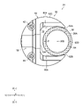
- FIG. 5 is an enlarged view of a main part showing the arrangement position of the pipeline member with respect to the curved part.
- FIG. 6 is an explanatory view of a main part in which the curved portion shown in FIG. 5 is covered with a rubber tube.
- FIG. 7 is an explanatory diagram showing some other modified examples of the pipeline member holding portion.
- FIG. 8 is an explanatory diagram showing some forms of a curved piece provided with a regulating member.
- FIG. 1 is an overall configuration diagram of the endoscope 10 according to the embodiment of the present invention.
- the endoscope 10 shown in FIG. 1 is, for example, a bronchoscope inserted into the trachea, the insertion portion 12 inserted into the trachea, and the hand operation portion 14 connected to the base end portion of the insertion portion 12.
- a universal cord 16 connected to the hand operation unit 14.
- the universal cord 16 is connected to a processor device, a light source device, or the like (not shown) via the connector 18 shown by the alternate long and short dash line in FIG.
- the insertion portion 12 has a long axis direction Ax from the tip end side to the proximal end side, and in order from the distal end side to the proximal end side, the tip rigid portion 20, the bendable bending portion 22, and the flexibility A flexible portion 24 having the above is provided.
- the curved portion 22 is an example of the curved portion of the present invention.
- the tip surface 21 of the tip rigid portion 20 is provided with a treatment tool outlet 28 which is an outlet of the treatment tool 26 such as forceps. Further, on the tip surface 21, an observation window and an illumination window (not shown) are provided at predetermined positions, respectively.
- An image sensor (not shown) is arranged on the back side (base end side) of the observation window, and an optical fiber cable (not shown) is placed on the back side (base end side) of the illumination window.
- the signal line and the optical fiber cable of the image sensor are inserted from the tip rigid portion 20 to the curved portion 22, the flexible portion 24, the hand operation unit 14, the universal cord 16 and the connector 18, respectively, and are inserted into the above-mentioned processor device and light source device, respectively. Be connected.
- a treatment tool channel 30 for inserting the treatment tool 26 is provided inside the insertion portion 12.
- the tip of the treatment tool channel 30 is connected to the treatment tool outlet 28, and the base end is connected to the channel opening 32 of the hand operation unit 14.
- a disposable type forceps plug 36 through which the treatment tool 26 can be inserted is detachably attached to the channel opening 32.
- the treatment tool channel 30 is used not only as a conduit for inserting the treatment tool 26, but also as a conduit for sucking body fluid such as blood or solid matter such as internal filth from the treatment tool outlet 28. ..
- the treatment tool channel 30 has flexibility and is an example of the conduit member of the present invention.
- a suction channel (not shown) branched from the treatment tool channel 30 is disposed inside the hand operation unit 14, and this suction channel is connected to the suction button 34 of the hand operation unit 14.
- the suction button 34 is connected to a suction pump (not shown) arranged outside the hand operation unit 14, and the suction channel and the suction pump are communicated or shut off by the pressing operation of the suction button 34 or the release of the pressing operation. Will be done.
- an angle lever 38 for bending the curved portion 22 is arranged on the hand operation unit 14.
- the angle lever 38 is rotatably provided about the rotation shaft 40 with respect to the hand operation unit 14.
- the angle lever 38 and the bending portion 22 are connected via two wires 42 and 44 (see FIG. 2) for bending operation arranged inside the insertion portion 12.
- the curved portion 22 shown in FIG. 2 is curved in two directions (for example, in the vertical direction).
- FIG. 2 is a perspective view showing the structure of the curved portion 22, and shows a form in which the curved portion 22 is curved upward.
- the front direction (the direction toward the tip end side of the long axis direction Ax of the insertion portion 12) at that time is the X (+) direction
- the rear direction (the direction toward the base end side of the long axis direction Ax of the insertion portion 12) is X. (-) Direction
- the right direction at that time is the Y (+) direction
- the left direction is the Y ( ⁇ ) direction.
- the insertion portion 12 is linear in the X-axis direction including the X (+) direction and the X (-) direction, and in the axial direction of the axis P of the curved piece 50 (see FIG. 3) constituting the curved portion 22 described later. It is parallel to the long axis direction Ax when it is arranged.
- the configuration of the hand operation unit 14 is not limited to the mode shown in FIG.
- a pair of angle knobs may be provided instead of the angle lever 38, and the curved portion 22 may be curved in the vertical direction and the horizontal direction by rotating the pair of angle knobs.
- a gas such as air and a cleaning liquid may be supplied to the tip rigid portion 20 by providing the air supply / water supply button on the hand operation unit 14 and operating the air supply / water supply button.
- the bending portion 22 shown in FIG. 2 includes a plurality of bending pieces 50 shown in FIG. 3, and is configured by connecting these bending pieces 50 along the axial direction of the axis P.
- the curved piece 50 is an example of the curved piece of the present invention.
- FIG. 4A to 4E of FIG. 4 show a five-view view of the curved piece 50 as viewed from five directions
- 4A is a front view (a view of the curved piece 50 seen from the side of the tip rigid portion 20)
- 4B is a plan view (a plan view).
- the curved piece 50 is viewed from the side in the Z (+) direction
- 4C is a rear view (the curved piece 50 is viewed from the side of the flexible portion 24)
- 4D is a right side view (the curved piece 50 is Y (+)).
- Is a left side view (a view of the curved piece 50 seen from the Y ( ⁇ ) direction).
- the curved piece 50 includes a piece main body 52, a first extending body 54, a second extending body 56, a connecting shaft 58, and a connecting hole 60.
- the piece main body 52 has a peripheral wall portion 62 having a C-shaped cross section orthogonal to the axial direction of the axis P, and one end 62A and the other end in the circumferential direction of the peripheral wall portion 62. It is configured in a ring shape having a slit-shaped opening 64 extending in the axial direction of the shaft P from 62B.
- the axis P is defined as the central axis of the piece main body 52 and will be described.
- the peripheral wall portion 62 of the piece main body 52 is based on a substantially cylindrical outer shape, and when the peripheral wall portion 62 is viewed from the axial direction of the axis P (hereinafter, also referred to as “X-axis direction”), The outer peripheral surface 62C of the peripheral wall portion 62 is formed in a C shape. Further, the peripheral wall portion 62 has substantially triangular arm portions 66 and 68 arranged on the Z (+) direction side and the Z ( ⁇ ) direction side of the axis P, respectively, and an opening portion sandwiching the axis P. It has a substantially fan-shaped base 70 arranged on the opposite side of 64.
- Arms 66 and 68 extend from the base 70 in the Y (+) direction, and one end 62A and the other end 62B are formed at the ends of the arms 66 and 68 on the Y (+) direction. ..
- the piece main body 52 configured in this way, when the piece main body 52 is viewed from the X-axis direction, the piece main body 52 is formed by the inner wall surfaces 66A, 68A, 70A of the arm portions 66, 68 and the base portion 70, respectively. It has a substantially rectangular space portion 72 to be imaged, and the space portion 72 is communicated with the opening portion 64 in the Y (+) direction.
- the space portion 72 functions as a space portion for arranging the pipeline member of the present invention.
- the C-shape that defines the shape of the outer peripheral surface 62C of the peripheral wall portion 62 includes not only the C-shape but also shapes similar to the C-shape such as the U-shape and the J-shape. That is, the C-shape refers to a shape in which the opening 64 and the peripheral wall portion 62 are continuously arranged in the circumferential direction of the space portion 72 so as to surround the inner space portion 72.
- the space portion 72 provided in the piece main body 52 is formed so as to penetrate the axis P, so that the size of the space portion 72 is secured as a space portion for arranging the conduit member.
- An endoscope built-in object such as the treatment tool channel 30, the signal line of the image sensor (not shown), and the optical fiber cable (not shown) shown in 2 is housed.
- one end 62A and the other end 62B of the peripheral wall portion 62 shown in FIG. 4 are projected from each other toward the side of the opening 64. That is, the one end 62A and the other end 62B are configured as the holding claws of the pipeline member holding portion of the present invention. Further, the distance (opening width) L between one end 62A and the other end 62B in the Z-axis direction is set shorter than the diameter of the treatment tool channel 30. According to the curved piece 50 having such one end 62A and the other end 62B, the outer peripheral surface 30A of the treatment tool channel 30 housed in the space 72 comes into contact with the one end 62A and the other end 62B, thereby causing the treatment tool. The channel 30 is held in the space portion 72 and is prevented from falling off from the space portion 72 through the opening 64.
- both one end 62A and the other end 62B are configured as holding claws, but the present invention is not limited to this, and at least one end of one end 62A and the other end 62B is used. It may be configured as the above-mentioned holding claw portion.
- one end 62A may be configured as a holding claw portion and the other end 62B may be configured flush with the inner wall surface 68A of the arm portion 68
- the other end 62B may be configured as a holding claw portion
- the other end 62A may be configured as the arm portion 66. It may be configured to be flush with the inner wall surface 66A of.
- the treatment tool channel 30 may be inserted and arranged along the axis P when being housed in the space portion 72, or may be inserted and arranged from the opening portion 64 into the space portion 72. That is, the treatment tool channel 30 may be pushed from the opening 64 in the radial direction orthogonal to the axial direction of the treatment tool channel 30 and inserted into the space portion 72.
- the treatment tool channel 30 the one having a perfect circular cross-sectional shape in the direction orthogonal to the axial direction of the treatment tool channel 30 is exemplified.
- the first extending body 54 extends from the peripheral wall portion 62 to the side of the soft portion 24 (the base end side of the curved piece 50), which is one side in the X-axis direction. Specifically, as shown in 4B of FIG. 4, the first extension body 54 extends from the surface 70B on the side of the soft portion 24 of the base 70 to the side of the soft portion 24 in parallel with the axis P. There is. Further, as shown in 4E of FIG. 4, the outer shape of the first extension body 54 is based on a substantially isosceles triangle, and when the first extension body 54 is viewed from the Y-axis direction, the first extension body 54 is the first extension body. The tip 54A of the body 54 is arranged at a position overlapping the axis P.
- the second extending body 56 extends from the peripheral wall portion 62 to the side of the tip rigid portion 20 (the tip side of the curved piece 50) which is the other side in the X-axis direction. Specifically, as shown in 4E of FIG. 4, the second extending body 56 extends from the surface 70C on the side of the tip rigid portion 20 of the base 70 to the side of the tip rigid portion 20 in parallel with the axis P. Has been done. Further, the outer shape of the second extension body 56 is based on a substantially isosceles triangle, and when the second extension body 56 is viewed from the Y-axis direction, the tip 56A of the second extension body 56 is an axis. It is arranged at a position overlapping with P. Further, as shown in 4B of FIG. 4, the second extension body 56 has an outer peripheral surface 56B formed along an extended surface of the outer peripheral surface 62C of the peripheral wall portion 62. The outer peripheral surface 56B corresponds to the outer peripheral surface of the second extension body of the present invention.
- the connecting shaft 58 is provided on the first extending body 54 and extends outward in the radial direction orthogonal to the X-axis direction. Specifically, the connecting shaft 58 is formed in a columnar shape and extends in the Y ( ⁇ ) direction from the outer end surface 54B of the first extending body 54 as shown by 4B and 4C in FIG. .. Further, the connecting shaft 58 has a tip surface 58A formed along a surface extending the outer peripheral surface 62C of the peripheral wall portion 62. The tip surface 58A corresponds to the tip surface of the connecting shaft of the present invention. As a result, as shown in 4C of FIG.
- the connecting shaft 58 when the connecting shaft 58 and the peripheral wall portion 62 are viewed from the X-axis direction, the connecting shaft 58 is an axis from the outer end surface 54B to the outer peripheral surface 62C in the Y-axis direction. Has a length. Further, as shown in 4E of FIG. 4, when the first extension body 54 is viewed from the Y-axis direction, the shaft 58B, which is the central axis of the connecting shaft 58, is arranged at a position overlapping the shaft P.
- the connecting hole 60 is provided in the second extending body 56.
- the connecting hole 60 is formed in a direction parallel to the connecting shaft 58 and has a hole shape corresponding to the outer shape of the connecting shaft 58.
- the connecting hole 60 is provided so as to penetrate the second extending body 56 in the Y-axis direction.
- the shaft 60A which is the central axis of the connecting hole 60, is arranged at a position overlapping the shaft P.
- the first extension body 54 of the curved piece 50 is a case where the first extension body 54 and the second extension body 56 are projected onto the virtual surface F orthogonal to the X-axis direction. In addition, it is arranged at an offset so as not to overlap with the second extension body 56. Specifically, when the first extension body 54 and the second extension body 56 are viewed from the X-axis direction, the outer end surface 54B of the first extension body 54 is inside the second extension body 56. It is arranged closer to the axis P than the end face 56C. By offsetting the first extension body 54 in this way, it is possible to set the axial length of the connecting shaft 58 protruding from the outer end surface 54B of the first extension body 54 to be longer.
- the curved piece 50 has a pair of wire insertion holes 74 and 76 formed so as to penetrate the peripheral wall portion 62 and the second extending body 56 along the X-axis direction. ..
- a wire 42 (see FIG. 2) is inserted into the wire insertion hole 74, and a wire 44 (see FIG. 2) is inserted into the wire insertion hole 76.
- the base end side of these wires 42 and 44 is connected to the angle lever 38 of FIG. 1, and the tip end side is connected to, for example, the bending piece 50 located at the tip of the bending portion 22.
- the pair of wire insertion holes 74 and 76 are located on both sides of the connection shaft 58 when the pair of wire insertion holes 74 and 76 and the connection shaft 58 are viewed from the X-axis direction. Is located in. Specifically, the pair of wire insertion holes 74, 76 are arranged at positions on both sides of the connecting shaft 58 in a direction (Z-axis direction) orthogonal to the axial direction (Y-axis direction) of the connecting shaft 58. There is. Further, the arrangement positions of the wire insertion holes 74 and 76 may be positions on both sides of the connecting shaft 58, but the wire insertion holes 74 and 76 of this example are Z as shown in 4C of FIG. It is provided at a symmetrical position sandwiching the connecting shaft 58 in the axial direction. The above is the configuration of the curved piece 50.
- the curved piece 50 configured as described above is, for example, a resin molded product using a resin material such as polyacetal.
- the curved piece 50 is not limited to the resin, and may be made of a metal such as stainless steel. However, from the viewpoint of manufacturing the curved piece 50, it is preferably made of a resin that can be easily manufactured by injection molding or the like.
- the bending portion 22 performs an assembly operation of inserting the connecting shaft 58 of one bending piece 50 adjacent to each other into the connecting hole 60 of the other bending piece 50 in all the bending pieces 50. Assembled by. After that, the wires 42 and 44 are inserted into the pair of wire insertion holes 74 and 76 of the plurality of curved pieces 50 connected to each other, respectively, and the base end side of the wires 42 and 44 is curved so as to be located at the tip of the curved portion 22. By connecting to the piece 50, the curved portion 22 with the wires 42 and 44 is assembled.
- FIG. 5 is an enlarged view of a main part of the bending piece 50 when the bending portion 22 with the wires 42 and 44 shown in FIG. 2 is viewed from the X ( ⁇ ) direction side, and is an arrangement position of the treatment tool channel 30 with respect to the bending portion 22. It is a figure which showed.
- the treatment tool channel 30 is arranged along the axial direction of the axis P over each space portion 72 of the plurality of curved pieces 50 connected.
- a part of the outer peripheral surface 30A of the treatment tool channel 30 is outside the virtual outer shape 62D formed by the surface extending the outer peripheral surface 62C of the peripheral wall portion 62 toward the opening 64 (Y (Y). +)
- the form arranged on the direction side) is shown.
- the shaft 30B which is the central axis thereof, is arranged in the Y (+) direction with respect to the shaft P, and the outer peripheral surface 30A thereof is one end 62A and the other end 62B of the peripheral wall portion 62. Is in contact with.
- the treatment tool outlet 28 for the tip surface 21 has a shaft similar to the axis 30B of the treatment tool channel 30. It is arranged closer to the Y (+) direction with respect to P.
- FIG. 6 is an enlarged view of a main part of the curved portion 22 showing that the outer peripheral surface of the plurality of curved pieces 50 connected to each other is covered with the rubber tube 78 constituting the outer cover.
- the rubber tube 78 is an example of the covering member of the present invention.
- the covering member is not limited to the rubber tube 78, but it is preferable to use an elastic rubber tube because the covering member can be tightly fitted to the outer peripheral surfaces of a plurality of connected curved pieces 50.
- a resin-based elastomer tube such as fluorine rubber or silicone rubber can be exemplified. It is not essential that the covering member is tightly fitted to the outer peripheral surface of the curved piece 50, but the diameter of the curved portion 22 can be reduced by tightly fitting the covering member to the outer peripheral surface of the curved piece 50 as in this example. preferable.
- the bending piece 50, the bending portion 22, and the endoscope 10 configured as described above have the following effects.
- the connecting shaft 58 is provided on the first extending body 54 of the piece main body 52, and is connected to the second extending body of the piece main body 52 in parallel with the connecting shaft 58. Since the curved portion 22 can be assembled by providing the connecting hole 60 having a hole shape corresponding to the outer shape of the shaft 58 and inserting the connecting shaft 58 into the connecting hole 60, the curved portion 22 can be easily assembled. As a result, according to the bending piece 50, the bending portion 22, and the endoscope 10 of the present embodiment, the assembling property of the bending portion 22 is improved.
- the first extension body 54 and the second extension body 56 are projected onto the virtual surface F orthogonal to the X-axis direction
- the first extension body 54 and the second extension body 56 are projected onto the virtual surface F.
- the 1 extension body 54 is offset-arranged at a position where it does not overlap with the second extension body, the axial length of the connecting shaft 58 (fitting length with the connecting hole 60) can be made longer.
- two adjacent curved pieces 50 can be stably connected to each other.
- the first extension of one of the curved pieces 50 adjacent to each other is extended. It is possible to prevent the body 54 from interfering with the second extending body 56 of the other curved piece 50.
- the second extending body 56 has an outer peripheral surface 56B formed along an extended surface of the outer peripheral surface 62C of the peripheral wall portion 62, and is therefore connected.
- the rubber tube 78 can be tightly fitted to the outer peripheral surfaces of the plurality of curved pieces 50 (see FIG. 6).
- the connecting shaft 58 has a tip surface 58A formed along a surface extending the outer peripheral surface 62C of the peripheral wall portion 62, so that the above-mentioned tight fit is achieved. While doing so, the axial length of the connecting shaft 58 can be maximized (see FIG. 6). As a result, the two adjacent curved pieces 50 can be connected to each other more stably.
- the pair of wire insertion holes 74 and 76 sandwich the connection shaft 58 when the pair of wire insertion holes 74 and 76 and the connection shaft 58 are viewed from the X-axis direction. Since they are arranged at the positions on both sides, the force generated by the pushing / pulling operation of the wires 42 and 44, that is, the force for bending the curved portion 22, can be effectively transmitted to the curved piece 50. As a result, the curved portion 22 can be smoothly curved. If the wire insertion holes 74 and 76 of this example are provided at symmetrical positions with the connecting shaft 58 interposed therebetween, the curved portion 22 can be curved upward and downward with the same force. The feeling of bending operation can be made constant.
- the treatment tool channel 30 arranged in the space portion 72 is a space portion. It can be prevented from falling off from 72 through the opening 64.
- a plurality of connected portions of the outer peripheral surface 30A of the treatment tool channel 30 are arranged outside the virtual outer shape 62D.
- the outer peripheral surface of the curved piece 50 is covered with the rubber tube 78 (see FIG. 6).
- the rubber tube 78 is tightly fitted to the outer peripheral surfaces of the plurality of curved pieces 50 connected to each other.
- a part of the outer peripheral surface 30A of the treatment tool channel 30 arranged outside from the opening 64 is indicated by an arrow c due to the elastic force (diameter reduction force) of the rubber tube 78. It is pressed toward the axis P.
- the treatment tool channel 30 is deformed from a state in which its cross-sectional shape is a perfect circle to an elliptical shape having a major axis a in the Z-axis direction and a minor axis b in the Y-axis direction.
- the treatment tool channel 30 deformed to such a shape receives a force in the Z-axis direction from the curved portion 22 when the curved portion 22 is curved in the Z-axis direction, but the Z-axis direction is counteracted by the force. It is deformed into an elliptical shape having a major axis a. As a result, the treatment tool channel 30 is less likely to collapse in the direction of the major axis a when the curved portion 22 is curved, so that the generation of kink generated when the curved portion 22 is curved can be suppressed.
- 7A of FIG. 7 is an explanatory view of the curved piece 100 showing the first deformation example of the pipeline member holding portion
- 7B of FIG. 7 is the bending piece 110 showing the second deformation example of the pipeline member holding portion. It is explanatory drawing of.
- the same or similar members as the curved pieces 50 described in FIGS. 2 to 6 are designated by the same reference numerals and the description thereof will be omitted.
- the peripheral wall portion 102 has inner wall surfaces 66A, 68A, 70A defining the space portion 72. Further, the inner wall surfaces 66A, 68A, 70A include the inner wall surfaces 66A, 68A facing each other on both sides of the space portion 72. The inner wall surfaces 66A and 68A correspond to the pair of facing surfaces of the present invention.
- the pipeline member holding portion has holding groove portions 80 and 82 on the inner wall surfaces 66A and 68A.
- one end 102A and the other end 102B of the peripheral wall portion 102 are not configured as holding claws protruding toward the opening 64, and one end 102A is on the same surface as the inner wall surface 66A.
- the other end 102B is formed on the same surface as the inner wall surface 68A.
- the curved piece 100 shown in 7A of FIG. 7 has holding grooves 80 and 82 as a conduit member holding portion, but does not have a holding claw portion. Even in such a curved piece 100, the outer peripheral surface 30A of the treatment tool channel 30 (see FIG. 5) is accommodated in the holding grooves 80 and 82, so that the treatment tool channel 30 is held in the space portion 72 of the bending piece 100. be able to.
- the curved piece 100 in which the holding grooves 80 and 82 are formed on both of the inner wall surfaces 66A and 68A is shown, but the present invention is not limited to this, and one of the inner wall surfaces 66A and 68A is not limited to this. It suffices to have a holding groove on the inner wall surface.
- the peripheral wall portion 104 has inner wall surfaces 66A, 68A, 70A defining the space portion 72. Further, the inner wall surfaces 66A, 68A, 70A include the inner wall surfaces 66A, 68A facing each other on both sides of the space portion 72. The inner wall surfaces 66A and 68A correspond to the pair of facing surfaces of the present invention.
- the pipeline member holding portion has holding groove portions 84 and 86 on the inner wall surfaces 66A and 68A.
- one end 62A and the other end 62B of the peripheral wall portion 104 are configured as holding claws protruding toward the opening 64.
- the curved piece 110 shown in 7B of FIG. 7 has holding grooves 84 and 86 as a conduit member holding portion, and has one end 62A and the other end 62B which are holding claw portions. Even in such a curved piece 110, the outer peripheral surface 30A of the treatment tool channel 30 (see FIG. 5) is accommodated in the holding grooves 84 and 86 and is brought into contact with one end 62A and the other end 62B, whereby the treatment tool channel 30 can be held in the space 72 of the curved piece 110.
- 7B of FIG. 5 the outer peripheral surface 30A of the treatment tool channel 30 (see FIG. 5) is accommodated in the holding grooves 84 and 86 and is brought into contact with one end 62A and the other end 62B, whereby the treatment tool channel 30 can be held in the space 72 of the curved piece 110.
- both of the inner wall surfaces 66A and 68A is shown, but the present invention is not limited to this, and one of the inner wall surfaces 66A and 68A is not limited to this. It suffices to have a holding groove on the inner wall surface.
- both one end 62A and the other end 62B are configured as the holding claw portion, but one end may be configured as the holding claw portion.
- the treatment tool channel 30 held in the space portion 72 of the curved piece 50 receives a force in the arrow c direction due to the contraction force of the rubber tube 78 shown in FIG.
- the treatment tool channel 30 is the axis 30B of the treatment tool channel 30. It is desirable to regulate the movement in the radial direction (Y (-) direction) orthogonal to the axial direction.
- the first form shown in 8A of FIG. 8 is a form in which the restricting members 90 and 92 are provided on the curved piece 50 shown in FIG. In 8A of FIG. 8, the curved piece 50 shown in FIG. 5 is simply shown.
- the regulating members 90 and 92 are provided on the inner wall surfaces 66A and 68A of the peripheral wall portion 62, and by abutting on the outer peripheral surface 30A of the treatment tool channel 30 arranged in the space portion 72, the regulating members 90 and 92 are provided. The movement of the treatment tool channel 30 in the radial direction (Y ( ⁇ ) direction) is restricted.
- the restricting members 90 and 92 are configured as protruding portions protruding from the inner wall surfaces 66A and 68A toward the space portion 72. Further, the regulating members 90 and 92 are arranged at predetermined intervals in the Z-axis direction, and the positions in the Y-axis direction are the same. That is, the regulating members 90 and 92 are spaced apart on a straight line parallel to the Z-axis direction. Thereby, the movement of the treatment tool channel 30 in the radial direction (Y ( ⁇ ) direction) can be stably regulated.
- the curved piece 50 in which the restricting members 90 and 92 are provided on both of the inner wall surfaces 66A and 68A is shown, but the present invention is not limited to this, and the inner wall surfaces 66A and 68A are included in one of the inner wall surfaces 66A and 68A. It suffices to have a regulating member on the wall surface.
- the second form shown in 8B of FIG. 8 is a form in which the restricting members 90 and 92 are provided on the curved piece 100 shown in 7A of FIG. 7, and the curved piece 100 shown in 7A of FIG. 7 is simply shown. There is. Even in the second form in which the restricting members 90 and 92 are provided on the curved piece 100 having the holding groove portions 80 and 82, the movement of the treatment tool channel 30 in the radial direction (Y ( ⁇ ) direction) is stably regulated. Can be done.
- the bending piece 110 shown in 7B of FIG. 7 is provided with the regulating members 90 and 92, and the bending piece 110 shown in 7B of FIG. 7 is simply shown. There is. Even in the third embodiment in which the restricting members 90 and 92 are provided on the curved piece 110 having the holding groove portions 80 and 82 and the one end 62A and the other end 62B which are the holding claw portions, the radial direction of the treatment tool channel 30 (Y (-). ) Direction) movement can be stably regulated.
- the inner wall surface 70A of the curved piece 50 shown in FIG. 5 is moved closer to the axis 30B of the treatment tool channel 30 than the form of FIG. 5, and the inner wall surface 70A is treated.
- the inner wall surface 70A functions as a regulating member by abutting the outer peripheral surface 30A of the tool channel 30. Even in such a fourth embodiment, the movement of the treatment tool channel 30 in the radial direction (Y ( ⁇ ) direction) can be stably regulated.
- the technique of the present invention is not limited to the curved portion of the bronchoscope, and for example, other than a colonoscope or an enteroscopy. It can also be applied to the curved part of the endoscope. Further, the curved piece and the curved portion according to the present invention can be applied not only to an endoscope but also to a curved portion of a treatment tool (for example, see International Publication No. 2019/172318) which is one of medical instruments. Further, the present invention may be modified or modified without departing from the gist of the present invention.
Landscapes
- Health & Medical Sciences (AREA)
- Life Sciences & Earth Sciences (AREA)
- Surgery (AREA)
- Physics & Mathematics (AREA)
- Optics & Photonics (AREA)
- Medical Informatics (AREA)
- Heart & Thoracic Surgery (AREA)
- Biophysics (AREA)
- Nuclear Medicine, Radiotherapy & Molecular Imaging (AREA)
- Pathology (AREA)
- Radiology & Medical Imaging (AREA)
- Veterinary Medicine (AREA)
- Engineering & Computer Science (AREA)
- Biomedical Technology (AREA)
- Public Health (AREA)
- General Health & Medical Sciences (AREA)
- Molecular Biology (AREA)
- Animal Behavior & Ethology (AREA)
- Astronomy & Astrophysics (AREA)
- General Physics & Mathematics (AREA)
- Rehabilitation Therapy (AREA)
- Endoscopes (AREA)
Priority Applications (4)
| Application Number | Priority Date | Filing Date | Title |
|---|---|---|---|
| CN202180088415.7A CN116648654A (zh) | 2021-01-04 | 2021-12-21 | 医疗器具的弯曲件及弯曲部以及内窥镜 |
| JP2022573010A JP7724801B2 (ja) | 2021-01-04 | 2021-12-21 | 医療器具の湾曲駒及び湾曲部並びに内視鏡 |
| EP21915144.6A EP4272623A4 (en) | 2021-01-04 | 2021-12-21 | BENDING PIECE AND BENDING SECTION FOR MEDICAL INSTRUMENT, AND ENDOSCOPE |
| US18/330,370 US20230309803A1 (en) | 2021-01-04 | 2023-06-07 | Bending piece and bending portion of medical device, and endoscope |
Applications Claiming Priority (2)
| Application Number | Priority Date | Filing Date | Title |
|---|---|---|---|
| JP2021000035 | 2021-01-04 | ||
| JP2021-000035 | 2021-01-04 |
Related Child Applications (1)
| Application Number | Title | Priority Date | Filing Date |
|---|---|---|---|
| US18/330,370 Continuation US20230309803A1 (en) | 2021-01-04 | 2023-06-07 | Bending piece and bending portion of medical device, and endoscope |
Publications (1)
| Publication Number | Publication Date |
|---|---|
| WO2022145284A1 true WO2022145284A1 (ja) | 2022-07-07 |
Family
ID=82259278
Family Applications (1)
| Application Number | Title | Priority Date | Filing Date |
|---|---|---|---|
| PCT/JP2021/047236 Ceased WO2022145284A1 (ja) | 2021-01-04 | 2021-12-21 | 医療器具の湾曲駒及び湾曲部並びに内視鏡 |
Country Status (5)
| Country | Link |
|---|---|
| US (1) | US20230309803A1 (https=) |
| EP (1) | EP4272623A4 (https=) |
| JP (1) | JP7724801B2 (https=) |
| CN (1) | CN116648654A (https=) |
| WO (1) | WO2022145284A1 (https=) |
Cited By (2)
| Publication number | Priority date | Publication date | Assignee | Title |
|---|---|---|---|---|
| CN116570219A (zh) * | 2023-05-31 | 2023-08-11 | 湖南省华芯医疗器械有限公司 | 主动弯曲段和内窥镜 |
| CN116570221A (zh) * | 2023-05-31 | 2023-08-11 | 湖南省华芯医疗器械有限公司 | 一种蛇骨结构、主动弯曲段、插入部和内窥镜 |
Families Citing this family (2)
| Publication number | Priority date | Publication date | Assignee | Title |
|---|---|---|---|---|
| CN121015110B (zh) * | 2025-10-29 | 2026-02-17 | 湖南省华芯医疗器械有限公司 | 插入部和内窥镜 |
| CN121040829B (zh) * | 2025-11-03 | 2026-02-13 | 湖南省华芯医疗器械有限公司 | 远端结构、插入部和内窥镜 |
Citations (8)
| Publication number | Priority date | Publication date | Assignee | Title |
|---|---|---|---|---|
| JPH01122702U (https=) * | 1988-02-17 | 1989-08-21 | ||
| JPH01152604U (https=) | 1988-04-14 | 1989-10-20 | ||
| JP2011156269A (ja) | 2010-02-03 | 2011-08-18 | Olympus Medical Systems Corp | 内視鏡 |
| JP2012192080A (ja) * | 2011-03-17 | 2012-10-11 | Fujifilm Corp | 内視鏡装置 |
| WO2015108044A1 (ja) * | 2014-01-15 | 2015-07-23 | テルモ株式会社 | 医療用保持デバイス |
| JP2015160078A (ja) * | 2014-02-28 | 2015-09-07 | パナソニックIpマネジメント株式会社 | 内視鏡 |
| JP3216707U (ja) * | 2018-01-02 | 2018-06-14 | 珠海嘉潤医用影像科技有限公司Zhuhai Kaden Medical Imaging Technology Co., Ltd | 使い捨て内視鏡のための湾曲部 |
| WO2019172318A1 (ja) | 2018-03-07 | 2019-09-12 | 富士フイルム株式会社 | 処置具、内視鏡装置、内視鏡システム及び処置方法 |
Family Cites Families (6)
| Publication number | Priority date | Publication date | Assignee | Title |
|---|---|---|---|---|
| JPH06320473A (ja) * | 1993-05-11 | 1994-11-22 | Olympus Optical Co Ltd | 多関節マニピュレータ |
| JP2008253501A (ja) * | 2007-04-04 | 2008-10-23 | Olympus Corp | 内視鏡の湾曲管、内視鏡、および、内視鏡の湾曲管の各節輪を製造する製造方法 |
| JP2008259634A (ja) * | 2007-04-11 | 2008-10-30 | Olympus Corp | 内視鏡用可撓管と環状連結部材との連結構造 |
| JP2009142390A (ja) * | 2007-12-12 | 2009-07-02 | Olympus Corp | 内視鏡の湾曲部と内視鏡の湾曲部の製造方法 |
| JP5420355B2 (ja) * | 2009-09-10 | 2014-02-19 | オリンパス株式会社 | 内視鏡湾曲部 |
| EP3199088A4 (en) * | 2015-06-16 | 2018-07-18 | Olympus Corporation | Endoscope |
-
2021
- 2021-12-21 EP EP21915144.6A patent/EP4272623A4/en active Pending
- 2021-12-21 CN CN202180088415.7A patent/CN116648654A/zh active Pending
- 2021-12-21 WO PCT/JP2021/047236 patent/WO2022145284A1/ja not_active Ceased
- 2021-12-21 JP JP2022573010A patent/JP7724801B2/ja active Active
-
2023
- 2023-06-07 US US18/330,370 patent/US20230309803A1/en active Pending
Patent Citations (8)
| Publication number | Priority date | Publication date | Assignee | Title |
|---|---|---|---|---|
| JPH01122702U (https=) * | 1988-02-17 | 1989-08-21 | ||
| JPH01152604U (https=) | 1988-04-14 | 1989-10-20 | ||
| JP2011156269A (ja) | 2010-02-03 | 2011-08-18 | Olympus Medical Systems Corp | 内視鏡 |
| JP2012192080A (ja) * | 2011-03-17 | 2012-10-11 | Fujifilm Corp | 内視鏡装置 |
| WO2015108044A1 (ja) * | 2014-01-15 | 2015-07-23 | テルモ株式会社 | 医療用保持デバイス |
| JP2015160078A (ja) * | 2014-02-28 | 2015-09-07 | パナソニックIpマネジメント株式会社 | 内視鏡 |
| JP3216707U (ja) * | 2018-01-02 | 2018-06-14 | 珠海嘉潤医用影像科技有限公司Zhuhai Kaden Medical Imaging Technology Co., Ltd | 使い捨て内視鏡のための湾曲部 |
| WO2019172318A1 (ja) | 2018-03-07 | 2019-09-12 | 富士フイルム株式会社 | 処置具、内視鏡装置、内視鏡システム及び処置方法 |
Cited By (3)
| Publication number | Priority date | Publication date | Assignee | Title |
|---|---|---|---|---|
| CN116570219A (zh) * | 2023-05-31 | 2023-08-11 | 湖南省华芯医疗器械有限公司 | 主动弯曲段和内窥镜 |
| CN116570221A (zh) * | 2023-05-31 | 2023-08-11 | 湖南省华芯医疗器械有限公司 | 一种蛇骨结构、主动弯曲段、插入部和内窥镜 |
| CN116570219B (zh) * | 2023-05-31 | 2025-11-25 | 湖南省华芯医疗器械有限公司 | 主动弯曲段和内窥镜 |
Also Published As
| Publication number | Publication date |
|---|---|
| CN116648654A (zh) | 2023-08-25 |
| EP4272623A4 (en) | 2024-09-18 |
| JPWO2022145284A1 (https=) | 2022-07-07 |
| EP4272623A1 (en) | 2023-11-08 |
| JP7724801B2 (ja) | 2025-08-18 |
| US20230309803A1 (en) | 2023-10-05 |
Similar Documents
| Publication | Publication Date | Title |
|---|---|---|
| WO2022145284A1 (ja) | 医療器具の湾曲駒及び湾曲部並びに内視鏡 | |
| CN115969295B (zh) | 一种内窥镜复合插入部的刚度调节机构及内窥镜 | |
| CN108601508B (zh) | 内窥镜的弯曲操作机构 | |
| US9635999B2 (en) | Endoscope | |
| JP5572782B1 (ja) | 挿入補助具、挿入本体及び挿入装置 | |
| CN107072494A (zh) | 内窥镜 | |
| CN104203076A (zh) | 旋转单元、插入装置、插入体、配设有该插入体的插入装置、以及具有插入体和插入装置的插入系统 | |
| US20200268238A1 (en) | Articulated tip part for an endoscope | |
| JP7818431B2 (ja) | 内視鏡 | |
| US20130253271A1 (en) | Endoscope | |
| US20200146536A1 (en) | Endoscope | |
| WO2017002423A1 (ja) | 内視鏡 | |
| CN106604673A (zh) | 内窥镜 | |
| US20240172927A1 (en) | Bending portion of endoscope, endoscope, and manufacturing method of bending portion of endoscope | |
| CN118252455A (zh) | 内窥镜的弯曲部、内窥镜及可动部件 | |
| JP2024159990A (ja) | 内視鏡 | |
| EP3219248A1 (en) | Insertion instrument and insertion device | |
| JP2007097883A (ja) | 内視鏡の湾曲部構造 | |
| CN219021093U (zh) | 内窥镜用管件、导引鞘、插入部及内窥镜 | |
| WO2022153798A1 (ja) | 超音波内視鏡及びその先端ユニット | |
| JP6787640B2 (ja) | 挿入装置、外装部材の接続構造、内視鏡 | |
| JP3619554B2 (ja) | カバー式内視鏡 | |
| US20190239739A1 (en) | Endoscope | |
| JP2024173018A (ja) | 内視鏡用チューブ及び内視鏡 | |
| CN120661065A (zh) | 内窥镜 |
Legal Events
| Date | Code | Title | Description |
|---|---|---|---|
| 121 | Ep: the epo has been informed by wipo that ep was designated in this application |
Ref document number: 21915144 Country of ref document: EP Kind code of ref document: A1 |
|
| ENP | Entry into the national phase |
Ref document number: 2022573010 Country of ref document: JP Kind code of ref document: A |
|
| WWE | Wipo information: entry into national phase |
Ref document number: 202180088415.7 Country of ref document: CN |
|
| WWE | Wipo information: entry into national phase |
Ref document number: 2021915144 Country of ref document: EP |
|
| NENP | Non-entry into the national phase |
Ref country code: DE |
|
| ENP | Entry into the national phase |
Ref document number: 2021915144 Country of ref document: EP Effective date: 20230804 |