WO2022145002A1 - タービンハウジング、ターボチャージャおよびガソリンエンジン - Google Patents
タービンハウジング、ターボチャージャおよびガソリンエンジン Download PDFInfo
- Publication number
- WO2022145002A1 WO2022145002A1 PCT/JP2020/049197 JP2020049197W WO2022145002A1 WO 2022145002 A1 WO2022145002 A1 WO 2022145002A1 JP 2020049197 W JP2020049197 W JP 2020049197W WO 2022145002 A1 WO2022145002 A1 WO 2022145002A1
- Authority
- WO
- WIPO (PCT)
- Prior art keywords
- exhaust gas
- turbine housing
- inlet
- flow path
- turbine
- Prior art date
- Legal status (The legal status is an assumption and is not a legal conclusion. Google has not performed a legal analysis and makes no representation as to the accuracy of the status listed.)
- Ceased
Links
Images



Classifications
-
- F—MECHANICAL ENGINEERING; LIGHTING; HEATING; WEAPONS; BLASTING
- F02—COMBUSTION ENGINES; HOT-GAS OR COMBUSTION-PRODUCT ENGINE PLANTS
- F02B—INTERNAL-COMBUSTION PISTON ENGINES; COMBUSTION ENGINES IN GENERAL
- F02B37/00—Engines characterised by provision of pumps driven at least for part of the time by exhaust
- F02B37/12—Control of the pumps
- F02B37/18—Control of the pumps by bypassing exhaust from the inlet to the outlet of turbine or to the atmosphere
-
- F—MECHANICAL ENGINEERING; LIGHTING; HEATING; WEAPONS; BLASTING
- F02—COMBUSTION ENGINES; HOT-GAS OR COMBUSTION-PRODUCT ENGINE PLANTS
- F02B—INTERNAL-COMBUSTION PISTON ENGINES; COMBUSTION ENGINES IN GENERAL
- F02B37/00—Engines characterised by provision of pumps driven at least for part of the time by exhaust
- F02B37/12—Control of the pumps
- F02B37/18—Control of the pumps by bypassing exhaust from the inlet to the outlet of turbine or to the atmosphere
- F02B37/183—Arrangements of bypass valves or actuators therefor
-
- F—MECHANICAL ENGINEERING; LIGHTING; HEATING; WEAPONS; BLASTING
- F01—MACHINES OR ENGINES IN GENERAL; ENGINE PLANTS IN GENERAL; STEAM ENGINES
- F01D—NON-POSITIVE DISPLACEMENT MACHINES OR ENGINES, e.g. STEAM TURBINES
- F01D25/00—Component parts, details, or accessories, not provided for in, or of interest apart from, other groups
- F01D25/24—Casings; Casing parts, e.g. diaphragms, casing fastenings
-
- F—MECHANICAL ENGINEERING; LIGHTING; HEATING; WEAPONS; BLASTING
- F04—POSITIVE - DISPLACEMENT MACHINES FOR LIQUIDS; PUMPS FOR LIQUIDS OR ELASTIC FLUIDS
- F04D—NON-POSITIVE-DISPLACEMENT PUMPS
- F04D17/00—Radial-flow pumps, e.g. centrifugal pumps; Helico-centrifugal pumps
- F04D17/08—Centrifugal pumps
- F04D17/10—Centrifugal pumps for compressing or evacuating
-
- F—MECHANICAL ENGINEERING; LIGHTING; HEATING; WEAPONS; BLASTING
- F04—POSITIVE - DISPLACEMENT MACHINES FOR LIQUIDS; PUMPS FOR LIQUIDS OR ELASTIC FLUIDS
- F04D—NON-POSITIVE-DISPLACEMENT PUMPS
- F04D29/00—Details, component parts, or accessories
- F04D29/40—Casings; Connections of working fluid
- F04D29/42—Casings; Connections of working fluid for radial or helico-centrifugal pumps
- F04D29/4206—Casings; Connections of working fluid for radial or helico-centrifugal pumps especially adapted for elastic fluid pumps
-
- F—MECHANICAL ENGINEERING; LIGHTING; HEATING; WEAPONS; BLASTING
- F01—MACHINES OR ENGINES IN GENERAL; ENGINE PLANTS IN GENERAL; STEAM ENGINES
- F01D—NON-POSITIVE DISPLACEMENT MACHINES OR ENGINES, e.g. STEAM TURBINES
- F01D17/00—Regulating or controlling by varying flow
- F01D17/10—Final actuators
- F01D17/12—Final actuators arranged in stator parts
- F01D17/14—Final actuators arranged in stator parts varying effective cross-sectional area of nozzles or guide conduits
- F01D17/146—Final actuators arranged in stator parts varying effective cross-sectional area of nozzles or guide conduits by throttling the volute inlet of radial machines or engines
-
- F—MECHANICAL ENGINEERING; LIGHTING; HEATING; WEAPONS; BLASTING
- F01—MACHINES OR ENGINES IN GENERAL; ENGINE PLANTS IN GENERAL; STEAM ENGINES
- F01D—NON-POSITIVE DISPLACEMENT MACHINES OR ENGINES, e.g. STEAM TURBINES
- F01D25/00—Component parts, details, or accessories, not provided for in, or of interest apart from, other groups
- F01D25/08—Cooling; Heating; Heat-insulation
- F01D25/12—Cooling
-
- F—MECHANICAL ENGINEERING; LIGHTING; HEATING; WEAPONS; BLASTING
- F05—INDEXING SCHEMES RELATING TO ENGINES OR PUMPS IN VARIOUS SUBCLASSES OF CLASSES F01-F04
- F05D—INDEXING SCHEME FOR ASPECTS RELATING TO NON-POSITIVE-DISPLACEMENT MACHINES OR ENGINES, GAS-TURBINES OR JET-PROPULSION PLANTS
- F05D2220/00—Application
- F05D2220/40—Application in turbochargers
-
- Y—GENERAL TAGGING OF NEW TECHNOLOGICAL DEVELOPMENTS; GENERAL TAGGING OF CROSS-SECTIONAL TECHNOLOGIES SPANNING OVER SEVERAL SECTIONS OF THE IPC; TECHNICAL SUBJECTS COVERED BY FORMER USPC CROSS-REFERENCE ART COLLECTIONS [XRACs] AND DIGESTS
- Y02—TECHNOLOGIES OR APPLICATIONS FOR MITIGATION OR ADAPTATION AGAINST CLIMATE CHANGE
- Y02T—CLIMATE CHANGE MITIGATION TECHNOLOGIES RELATED TO TRANSPORTATION
- Y02T10/00—Road transport of goods or passengers
- Y02T10/10—Internal combustion engine [ICE] based vehicles
- Y02T10/12—Improving ICE efficiencies
Definitions
- the present disclosure relates to a turbine housing, a turbocharger including the turbine housing, and a gasoline engine including the turbocharger.
- Engines used in automobiles may be equipped with a turbocharger to improve engine output and fuel efficiency.
- the turbocharger rotates a turbine blade by the energy of a high-temperature fluid such as exhaust gas discharged from an engine, thereby rotating an impeller of a compressor mechanically connected to the turbine blade via a rotating shaft.
- the turbocharger compresses a gas (for example, air) used for combustion in the engine by a rotationally driven impeller and sends it to the engine.
- Patent Document 1 describes a turbine housing in which a wastegate passage (bypass flow path) for bypassing a part of exhaust gas without introducing it into a turbine blade is formed inside, a wastegate valve for opening and closing the wastegate passage, and a wastegate valve.
- a turbocharger equipped with is disclosed.
- Patent Document 2 discloses an exhaust gas purification catalyst provided in an exhaust system of an engine (internal combustion engine). The exhaust gas purification catalyst purifies harmful components contained in exhaust gas, such as hydrocarbons (HC), carbon monoxide (CO), and nitrogen oxides (NOx), and captures particulate matter (PM) contained in exhaust gas. It has a function to collect.
- HC hydrocarbons
- CO carbon monoxide
- NOx nitrogen oxides
- the performance of the exhaust gas purification catalyst is affected by the temperature of the catalyst and the concentration of oxygen. Therefore, the exhaust gas passing through the wastegate passage, that is, the exhaust gas whose energy has been recovered by the turbine blades and the temperature has not decreased, is sent to the exhaust gas purification catalyst arranged on the downstream side of the wastegate passage to raise the exhaust gas purification catalyst. May be warmed and rejuvenated. If the heat dissipation loss in the turbine housing of the exhaust gas passing through the wastegate passage is large, there is a possibility that the temperature rise of the exhaust gas purification catalyst cannot be effectively performed.
- the exhaust gas discharged from the engine becomes hotter than that of a diesel engine, and the temperature difference between the exhaust gas and the turbine housing increases, so that the heat radiation loss in the turbine housing increases. May increase. Therefore, it is necessary to suppress heat dissipation loss in the turbine housing of the exhaust gas passing through the wastegate passage.
- an object of at least one embodiment of the present disclosure is to suppress heat dissipation loss in the turbine housing of exhaust gas passing through the wastegate passage, and to raise the temperature of the exhaust gas purification catalyst arranged on the downstream side of the turbine housing. It is to provide a turbine housing, a turbocharger, and a gasoline engine that can be effectively performed.
- the turbine housing configured to house turbine blades driven by exhaust gas emitted from a gasoline engine.
- a scroll flow path wall surface forming a scroll flow path formed in a scroll shape for guiding the exhaust gas to the turbine blade.
- An exhaust gas discharge path wall surface that forms an exhaust gas discharge path for discharging the exhaust gas that has passed through the turbine blade, and a wastegate passage that bypasses the turbine blade and connects the scroll flow path and the exhaust gas discharge path are formed.
- the main body that has the wastegate passage wall surface inside, An inlet flange portion provided at the upstream end of the scroll flow path in the main body portion and having an inlet flange portion formed with an exhaust gas introduction port connected to the scroll flow path.
- the inlet-side opening edge of the wastegate passage formed on the scroll flow path wall surface is provided at a position where at least a part of the inlet-side opening edge is visible from the outside of the turbine housing through the exhaust gas introduction port.
- the turbocharger according to the embodiment of the present disclosure includes the turbine housing.
- the gasoline engine according to the embodiment of the present disclosure is A cylinder block with multiple cylinders and An exhaust manifold in which exhaust gas discharged from each of the plurality of cylinders merges, and at least a part of the exhaust manifold is provided inside the cylinder block.
- the turbocharger With the turbocharger, The inlet flange portion of the turbine housing was connected to the exhaust manifold.
- expressions such as “same”, “equal”, and “homogeneous” that indicate that things are in the same state not only represent exactly the same state, but also have tolerances or differences to the extent that the same function can be obtained. It shall also represent the existing state.
- an expression representing a shape such as a square shape or a cylindrical shape not only represents a shape such as a square shape or a cylindrical shape in a geometrically strict sense, but also an uneven portion or a chamfering within a range where the same effect can be obtained. It shall also represent the shape including the part and the like.
- the expression “includes”, “includes”, or “has” one component is not an exclusive expression that excludes the existence of another component.
- the same reference numerals may be given to similar configurations, and the description thereof may be omitted.
- FIG. 1 is a schematic configuration diagram schematically showing a configuration of an engine including a turbocharger according to an embodiment of the present disclosure.
- the turbocharger 2 according to some embodiments is mounted on the gasoline engine 1.
- the gasoline engine 1 includes a cylinder block 11 having a plurality of cylinders 12, an exhaust manifold 13 in which exhaust gas discharged from each of the plurality of cylinders 12 merges, and the turbocharger 2. At least prepare.
- the gasoline engine 1 has a compressed gas supply line 14 for guiding the compressed gas compressed by the turbocharger 2 to each of the plurality of cylinders 12, and a cooler 15 provided in the compressed gas supply line 14. Further, a water jacket 16 provided inside the cylinder block 11 and a refrigerant supply line 17 for supplying the gas to the water jacket 16 from the outside of the cylinder block 11 are further provided.
- the cooler 15 is configured to cool the compressed gas flowing through the compressed gas supply line 14.
- the water jacket 16 includes a flow path through which a refrigerant can flow, which is provided so as to surround each of the plurality of cylinders 12.
- the refrigerant supply line 17 is configured to supply the refrigerant to the water jacket 16.
- the compressed gas includes compressed air.
- the refrigerant includes cooling water.
- the refrigerant supply line 17 sends the cooling water storage tank 171 configured to store the cooling water and the cooling water stored in the cooling water storage tank 171 to the water jacket 16.
- One side of the cooling water supply pipe 172 is connected to the cooling water storage tank 171 and the other side is connected to the water jacket 16.
- the cooling water pump 173 is configured to send the cooling water to the other side of the cooling water supply pipe 172.
- the cooling water stored in the cooling water storage tank 171 is sent to the cooling water supply pipe 172, flows through the cooling water supply pipe 172 toward the other side, and then the water jacket. It is supplied to 16.
- a plurality of cylinders 12, cylinder blocks 11 and the like are cooled by the cooling water (refrigerant) in the water jacket 16.
- the turbocharger 2 rotatably accommodates a turbine blade 3, a compressor blade 21, a rotary shaft 22 connected to each of the turbine blade 3 and the compressor blade 21, and a turbine blade 3. It includes a turbine housing 4 configured as described above, and a compressor housing 23 configured to rotatably accommodate the compressor blades 21.
- the turbocharger 2 further comprises a bearing 24 that rotatably supports the rotary shaft 22 and a bearing housing 25 configured to accommodate the bearing 24.
- one side of the rotary shaft 22 in the longitudinal direction is connected to the turbine blade 3, and the other side in the longitudinal direction thereof is connected to the compressor blade 21.
- the rotary shaft 22 is rotatably supported by a bearing 24 between the turbine blade 3 and the compressor blade 21 in the longitudinal direction thereof.
- Each of the turbine blade 3 and the compressor blade 21 can be integrally rotated via the rotating shaft 22.
- the bearing housing 25 is arranged between the turbine housing 4 and the compressor housing 23, and is mechanically connected to each of the turbine housing 4 and the compressor housing 23 by fastening members (not shown) such as bolts and V-clamps. ..
- the turbine housing 4 is formed with an exhaust gas introduction port 41 for introducing exhaust gas into the turbine housing 4 and an exhaust gas discharge port 42 for discharging the exhaust gas to the outside.
- the compressor housing 23 is formed with a gas introduction port 231 for introducing gas into the compressor housing 23 and a gas discharge port 232 for discharging the gas that has passed through the compressor blades 21 to the outside.
- One side of the compressed gas supply line 14 is connected to the gas discharge port 232, and the other side is connected to each of the plurality of cylinders 12.
- the exhaust gas discharged from the exhaust manifold 13 is introduced into the turbine housing 4 through the exhaust gas introduction port 41. At least a part of the exhaust gas introduced inside the turbine housing 4 is guided to the turbine blade 3.
- the turbocharger 2 rotates the turbine blade 3 by the energy of the exhaust gas guided to the turbine blade 3. Since the compressor blade 21 is connected to the turbine blade 3 via the rotating shaft 22, it rotates in conjunction with the rotation of the turbine blade 3.
- the turbocharger 2 compresses the gas introduced into the inside of the compressor housing 23 through the gas introduction port 231 by the rotation of the compressor blade 21, and the compressed gas is discharged from the plurality of cylinders 12 through the gas discharge port 232 and the compressed gas supply line 14. It is configured to be sent to each.
- the compressed gas sent to each of the plurality of cylinders 12 burns together with the fuel to generate exhaust gas. Further, the exhaust gas that has passed through the turbine blade 3 is discharged to the outside of the turbine housing 4 through the exhaust gas discharge port 42.
- the gasoline engine 1 further comprises an exhaust gas purification catalyst 18 installed on the downstream side of the turbine housing 4.
- the exhaust gas discharged to the outside of the turbine housing 4 through the exhaust gas discharge port 42 is sent to the exhaust gas purification catalyst 18.
- the exhaust gas purification catalyst 18 purifies harmful components contained in the exhaust gas, for example, hydrocarbons (HC), carbon monoxide (CO), nitrogen oxides (NOx), and particulate matter (PM) contained in the exhaust gas. It has a function of collecting.
- the exhaust gas purification catalyst 18 may be any of a conventionally known three-way catalyst, an oxidation catalyst (DOC), a NOx adsorption reduction catalyst, and the like.
- the exhaust gas purification catalyst 18 may contain a carrier and a noble metal supported on the carrier.
- the noble metal supported on the carrier may contain at least one of rhodium (Rh), palladium (Pd), or platinum (Pt).
- the exhaust gas purification catalyst 18 activates the exhaust gas purification reaction by raising the temperature, for example, by the heat of the exhaust gas.
- FIG. 2 is a schematic cross-sectional view taken along the axis of the turbine housing according to the embodiment of the present disclosure.
- the turbine housing 4 includes a main body 5.
- the main body 5 has a scroll flow path wall surface 6 forming a scroll flow path 60 formed in a scroll shape for guiding the exhaust gas to the turbine blade 3, and an exhaust gas discharge path 70 for discharging the exhaust gas that has passed through the turbine blade 3.
- It has an exhaust gas discharge path wall surface 7 to be formed, and a wastegate passage wall surface 8 forming a wastegate passage 80 that bypasses the turbine blade 3 and connects the scroll flow path 60 and the exhaust gas discharge path 70.
- the upstream side in the exhaust gas flow direction may be simply referred to as an upstream side
- the downstream side in the exhaust gas flow direction may be simply referred to as a downstream side.
- the exhaust gas introduction port 41 described above is connected to the scroll flow path 60
- the exhaust gas discharge port 42 described above is connected to the exhaust gas discharge path 70.
- the turbine housing 4 accommodates the turbine blade 3 on the inner peripheral side of the scroll flow path 60.
- the direction in which the axis LA of the turbine blade 3 extends is defined as the axial direction X
- the direction orthogonal to the axis LA is defined as the radial direction Y.
- the side (on the right side in FIG. 2) where the exhaust gas discharge port 42 is located with respect to the turbine blade 3 is defined as the turbine side XF.
- the side opposite to the turbine side XF that is, the side where the turbine blade 3 is located with respect to the exhaust gas discharge port 42 (left side in FIG. 2) is defined as the compressor side XR.
- the turbine blade 3 includes a hub 31 and a plurality of turbine blades 33 provided on the outer surface 32 of the hub 31. Since the hub 31 is connected to the one side in the longitudinal direction of the rotary shaft 22, the hub 31 and the plurality of turbine blades 33 can rotate integrally with the rotary shaft 22 around the axis LA of the turbine blade 3. It has become.
- the hub 31 is formed in a concave curved shape in which the outer surface 32 thereof increases in distance from the axis LA as the outer surface 32 goes from the turbine side XF to the compressor side XR.
- the plurality of turbine blades 33 are arranged so as to be spaced apart from each other in the circumferential direction around the axis LA.
- the turbine housing 4 has a shroud surface 44 internally including a convex curved surface 43 formed in a convex curved shape in which the distance from the axis LA increases toward the compressor side XR from the turbine side XF.
- the convex curved surface 43 has a gap formed between the tip 34 of each of the plurality of turbine blades 33.
- the shroud surface 44 is formed between the scroll flow path wall surface 6 and the exhaust gas discharge path wall surface 7.
- the downstream end 441 of the shroud surface 44 is connected to the scroll flow path wall surface 6, and the upstream end 442 of the shroud surface 44 is connected to the exhaust gas discharge path wall surface 7.
- the turbine blade 3 is arranged between the scroll flow path 60 and the exhaust gas discharge path 70, and is configured to guide the exhaust gas introduced from the outside in the radial direction Y through the scroll flow path 60 to the turbine side XF in the axial direction X.
- the exhaust gas discharge path 70 is configured to guide the exhaust gas that has passed through the turbine blade 3 from the compressor side XR in the axial direction X to the turbine side XF.
- the exhaust gas that has passed through the turbine blades 3 flows through the exhaust gas discharge path 70 toward the turbine side XF, and then is discharged to the outside of the turbine housing 4 from the exhaust gas discharge port 42.
- the turbine housing 4 has an inlet-side opening edge 81 of the wastegate passage 80 formed on the scroll flow path wall surface 6 and an outlet-side opening edge 82 of the wastegate passage 80 formed on the exhaust gas discharge path wall surface 7.
- the wastegate passage wall surface 8 is connected to the scroll flow path wall surface 6 via the inlet side opening edge 81, and is connected to the exhaust gas discharge path wall surface 7 via the outlet side opening edge 82.
- the wastegate passage 80 has an inlet opening 810 formed inside the inlet side opening edge 81 and an outlet opening 820 formed inside the outlet side opening edge 82. In the wastegate passage 80, the inlet opening 810 is connected to the scroll flow path 60, and the outlet opening 820 is connected to the exhaust gas discharge passage 70.
- the turbocharger 2 further includes a wastegate valve 26 configured to be able to open and close the outlet opening 820 of the wastegate passage 80.
- the wastegate valve 26 includes a valve body 261 that closes the outlet opening 820, and a valve body driving unit 262 that supports the valve body 261 and is configured to be able to drive the valve body 261.
- the wastegate valve 26 drives the valve body 261 by the valve body drive unit 262 and closes or opens the outlet opening 820 to control the flow rate of the exhaust gas flowing from the wastegate passage 80 to the exhaust gas discharge path 70. ing.
- the amount of exhaust gas sent to the turbine blade 3 by opening the outlet opening 820 by the wastegate valve 26 and dividing a part of the exhaust gas flowing through the scroll flow path 60 toward the turbine blade 3 into the wastegate passage 80.
- the thermal energy can be reduced, and thus the boost pressure of the compressed gas sent to each of the plurality of cylinders 12 can be reduced.
- FIG. 2 schematically shows a plane in which the axis LA of the turbine blade 3 and the center C1 of the outlet opening 820 are present.
- the exhaust gas discharge path wall surface 7 is an inclined surface that inclines at least a part in the circumferential direction so that the distance to the axis LA increases toward the turbine side XF.
- 71 includes a valve accommodating surface 73 extending from the downstream end 72 of the inclined surface 71 to the turbine side XF along the axial direction X.
- the exhaust gas discharge path 70 described above includes a valve accommodating space 70A in which the valve body 261 of the wastegate valve 26 is accommodated.
- the valve accommodating space 70A is defined by an inclined surface 71 and a valve accommodating surface 73.
- the outlet side opening edge 82 is formed on at least one of the inclined surface 71 and the valve accommodating surface 73, and the outlet opening 820 is connected to the valve accommodating space 70A.
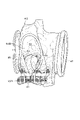
- FIG. 3 is an explanatory diagram for explaining the turbine housing according to the embodiment of the present disclosure.
- FIG. 3 schematically shows the turbine housing 4 in a plan view viewed from the outlet side (turbine side XF) of the exhaust gas discharge path 70 along the axis LA.
- the turbine housing 4 includes the main body portion 5 and the inlet flange portion 9 described above.
- the inlet flange portion 9 is provided at the upstream end 61 of the scroll flow path 60 in the main body portion 5, and includes a flange portion 91 projecting to the outer peripheral side.
- the above-mentioned exhaust gas introduction port 41 connected to the scroll flow path 60 is formed in the inlet flange portion 9.
- the inlet flange portion 9 is connected to the exhaust manifold 13. Therefore, the exhaust gas flows into the scroll flow path 60 from the exhaust manifold 13 through the exhaust gas introduction port 41.
- the turbine housing 4 is formed in its shape by casting.
- the turbine housing 4 has the above-mentioned scroll flow path wall surface 6, the exhaust gas discharge path wall surface 7, and the above-mentioned main body portion 5 having the wastegate passage wall surface 8 inside.
- the above-mentioned inlet flange portion 9 having an exhaust gas introduction port 41 connected to the scroll flow path 60 is provided.
- the inlet-side opening edge 81 of the wastegate passage 80 formed on the scroll flow path wall surface 6 is provided at a position where at least a part of the inlet-side opening edge 81 is visible from the outside of the turbine housing 4 through the exhaust gas introduction port 41. ..
- the scroll flow path wall surface 6 has a scroll outer wall surface 6A forming the outer peripheral side of the scroll flow path 60 and an inner peripheral side of the scroll outer wall surface 6A.
- a scroll inner wall surface 6B which is formed in and forms a scroll flow path 60 with the scroll outer wall surface 6A.
- the scroll inner wall surface 6B forms the inner peripheral side of the scroll flow path 60.
- the tangent line TL that passes through the upstream end 61A (outer peripheral end of the exhaust gas introduction port 41) of the scroll outer wall surface 6A and is in contact with the scroll inner wall surface 6B and the scroll inner wall surface 6B are in contact with each other.
- the contact point is P1.
- the above-mentioned entrance side opening edge 81 is provided on the upstream side of the contact point P1 on the scroll inner wall surface 6B.
- at least a part of the inlet side opening edge 81 is provided at a position visible from the outside of the turbine housing 4 through the exhaust gas introduction port 41. Even if the inlet side opening edge 81 cannot be visually recognized from the outside of the turbine housing 4 through the exhaust gas introduction port 41, from the outside of the turbine housing 4 through the exhaust gas introduction port 41 from the inlet side opening edge 81 on the scroll inner wall surface 6B.
- the downstream side (tongue portion P2 side) is visible, the inlet side opening edge 81 is provided at a position visible from the outside of the turbine housing 4 through the exhaust gas introduction port 41.
- the inlet side opening edge 81 connects the upstream end 61B (inner peripheral end of the exhaust gas introduction port 41) of the scroll inner wall surface 6B and the tongue portion P2 in a plan view as shown in FIG. At least a part of the inlet side opening edge 81 is provided on the upstream side (upstream end 61B side) of the center position P3 of the length of the curve.
- the turbine housing 4 is provided at a position where at least a part of the inlet side opening edge 81 of the wastegate passage 80 can be visually recognized from the outside of the turbine housing 4 through the exhaust gas introduction port 41.
- the length of the scroll flow path 60 (upstream scroll flow path 60A) between the inlet opening 810 of the wastegate passage 80 and the exhaust gas introduction port 41 of the inlet flange portion 9 is short. ..
- the exhaust gas passing through the wastegate passage 80 that is, the exhaust gas flowing into the wastegate passage 80 from the exhaust gas introduction port 41 through the upstream scroll flow path 60A. It is possible to suppress heat dissipation loss in the upstream scroll flow path 60A.
- the turbine housing 4 When the turbine housing 4 is mounted on the gasoline engine 1, the exhaust gas discharged from the gasoline engine 1 becomes hotter than when mounted on another internal combustion engine such as a diesel engine, and the exhaust gas and the turbine housing 4 are mounted. Since the temperature difference between the turbine housing 4 and the turbine housing 4 increases, the heat dissipation loss in the turbine housing 4 may increase. According to the above configuration, even when the turbine housing 4 is mounted on the gasoline engine 1, the heat dissipation loss of the exhaust gas passing through the wastegate passage 80 in the turbine housing 4 can be effectively suppressed.
- the exhaust gas discharge path 70 described above extends the axis LA of the turbine blade 3. It is configured to guide the exhaust gas from one side (compressor side XR) in the existing direction (axial direction X) to the other side (turbine side XF).
- a normal line N1 (a straight line passing through the center C1 and perpendicular to the exit opening 820) passing through the center C1 of the outlet opening 820 of the wastegate passage 80 extends in a direction intersecting the axis LA of the turbine blade 3. It is configured as follows.
- the scroll flow path 60 is formed in a spiral shape toward the compressor side XR in the axial direction X toward the downstream side (turbine blade 3 side). Therefore, the portion on the upstream side of the scroll flow path 60 is provided on the outer peripheral side of the exhaust gas discharge path 70.
- the wastegate passage 80 extends along the radial direction and is inclined so that the center C1 of the outlet opening 820 is located closer to the turbine side XF than the center C2 of the inlet opening 810.
- Each of the entrance opening 810 and the exit opening 820 opens in a direction along the extending direction of the normal N1.
- the outlet opening 820 is connected to the exhaust gas discharge path 70, and the inlet opening 810 is connected to the scroll flow path 60 provided on the outer peripheral side of the exhaust gas discharge path 70.
- the wastegate passage 80 is configured such that the normal N1 passing through the center C1 of the outlet opening 820 extends in a direction intersecting the axis LA of the turbine blade 3.
- the length of the wastegate passage 80 (distance from the inlet opening 810 to the outlet opening 820) as compared with the case where the normal N1 extends along the direction in which the axis LA of the turbine blade 3 extends. ) Can be shortened.
- the length of the wastegate passage 80 can be shortened.
- the angle ⁇ satisfies 30 ° ⁇ ⁇ ⁇ 60 °
- the exhaust gas flowing into the exhaust gas discharge path 70 from the outlet opening 820 of the wastegate passage 80 is guided to the exhaust gas discharge port 42 by the exhaust gas discharge path wall surface 7. Therefore, the exhaust gas can be discharged to the outside of the turbine housing 4 from the exhaust gas discharge port 42.
- the flow of the exhaust gas passing through the wastegate passage 80 in the exhaust gas discharge path 70 can be improved, the heat dissipation loss in the exhaust gas discharge path 70 of the exhaust gas passing through the wastegate passage 80 can be suppressed.
- the turbocharger 2 includes the turbine housing 4 described above, as shown in FIG.
- the turbocharger 2 since the turbocharger 2 has a short length of the upstream scroll flow path 60A of the turbine housing 4, it is possible to suppress the heat dissipation loss in the upstream scroll flow path 60A of the exhaust gas passing through the wastegate passage 80, and thus the heat dissipation loss in the upstream scroll flow path 60A can be suppressed.
- the temperature of the exhaust gas purification catalyst 18 arranged on the downstream side of the turbine housing 4 can be effectively raised.
- the gasoline engine 1 is discharged from each of the above-mentioned turbocharger 2, the above-mentioned cylinder block 11 having a plurality of cylinders 12, and the plurality of cylinders 12.
- the exhaust manifold 13 described above with which the exhaust gas merges is provided. At least a part of the exhaust manifold 13 is provided inside the cylinder block 11.
- the inlet flange portion 9 of the turbine housing 4 described above is connected to the exhaust manifold 13.
- the exhaust gas discharged from each of the plurality of cylinders 12 flows into the scroll flow path 60 from the exhaust gas introduction port 41 of the inlet flange portion 9 after passing through the exhaust manifold 13.
- At least a part of the exhaust manifold 13 is provided inside a cylinder block 11 having a plurality of cylinders 12, and an inlet flange portion 9 is connected to the exhaust manifold 13. In this case, the heat dissipation loss in the exhaust manifold 13 of the exhaust gas discharged from each of the plurality of cylinders 12 can be suppressed.
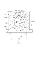
- FIG. 4 is an explanatory diagram for explaining an inlet-side opening edge of a wastegate passage of a turbine housing according to an embodiment of the present disclosure.
- the normal line N2 passing through the center C2 passing through the center C2 of the entrance opening 810 of the wastegate passage 80 in front of the entrance side opening edge 81 of the scroll inner wall surface 6B (scroll flow path wall surface 6) described above.
- the turbine housing 4 in a plan view viewed from the scroll flow path 60 side along the straight line perpendicular to the inlet opening 810) is schematically shown.
- the inlet side opening edge 81 described above is formed in an annular shape when viewed from the front.
- the entrance side opening edge 81 may be formed in an elliptical ring shape when viewed from the front, or may be formed in a rectangular ring shape when viewed from the front.
- the inlet-side opening edge 81 includes a downstream end portion 83 including a downstream end 831 in the inlet-side opening edge 81, an upstream end portion 84 including an upstream end 841 in the inlet-side opening edge 81, and an inlet. Includes one side end 85 including one end 851 of the opening width direction W in the side opening edge 81 and the other side end 86 including the other end 861 of the opening width direction W in the inlet side opening edge 81.
- the temperature of the exhaust gas introduced into the turbine housing 4 tends to be high (for example, 1000 ° C. or higher).
- the length of the scroll flow path 60 upstream side scroll flow path 60A
- the inlet side opening is shortened.
- the edge 81 will be exposed to a higher temperature exhaust gas than before.
- FIG. 5 is an explanatory diagram for explaining the thermal elongation of the turbine housing according to the embodiment of the present disclosure.
- FIG. 5 shows the analysis result of the thermal strain of the turbine housing 4 described above, and the larger the thermal strain, the darker the display.
- the inlet side opening edge 81 is on the downstream side (the side separated from the exhaust gas introduction port 41 in the extending direction of the axis LB of the exhaust gas introduction port 41) due to the heat of the exhaust gas flowing through the scroll flow path 60.
- the end (downstream end 83) of (upper side in FIG. 4) heat elongation occurs along the opening width direction W (left-right direction in FIG. 4).
- the inlet flange portion 9 Since the inlet flange portion 9 is connected to the exhaust manifold 13, it is cooled by the cooling water (refrigerant) in the water jacket 16. Therefore, the end portion (upstream end portion 84) of the upstream side (upstream end portion 84) of the inlet side opening edge 81 (the side close to the exhaust gas introduction port 41 in the extending direction of the axis LB, the lower middle side in FIG. 4) is located at the downstream end portion 83. In comparison, thermal elongation along the opening width direction W is suppressed. Due to the difference in thermal elongation between the upstream end 84 and the downstream end 83 of the inlet side opening edge 81, as shown in FIG.
- 6 and 7 are explanatory views for explaining the inlet-side opening edge of the wastegate passage of the turbine housing according to the embodiment of the present disclosure.
- 6 and 7 schematically show a state in which the entrance side opening edge 81 of the scroll inner wall surface 6B (scroll flow path wall surface 6) described above is viewed from the front, that is, from the scroll flow path 60 side. ..
- the inlet side opening edge 81 of the turbine housing 4 described above is provided at the downstream end 83 including the downstream end 831 of the inlet side opening edge 81.
- the stress concentration portion 100 is included.
- the stress concentration unit 100 is configured so that when the inlet side opening edge 81 is exposed to the heat of the exhaust gas, the stress due to thermal elongation is concentrated.
- the downstream end portion 83 includes a region including a downstream end 831 provided on the downstream side of each of the one end 851 and the other end 861 of the inlet side opening edge 81.
- the downstream end portion 83 stress concentration portion 100 is provided at the central portion of the inlet side opening edge 81 in the opening width direction W.
- the length of the opening width direction W at the entrance side opening edge 81 is maximum, one end 851.
- the downstream end portion 83 stress concentration portion 100
- the downstream end portion 83 has a distance W2 from the one end 851 in the opening width direction W (direction toward the other end 861). Is positive) is provided within the range satisfying the condition of 0.25W1 ⁇ W2 ⁇ 0.75W1.
- the inlet side opening edge 81 includes a stress concentration portion 100 provided at the downstream end portion 83 of the inlet side opening edge 81 so that stress due to thermal elongation is concentrated.
- stress concentration due to thermal elongation is initially generated by the heat of the exhaust gas flowing through the turbine housing 4, and cracks are generated.
- a portion of the inlet side opening edge 81 other than the downstream end portion 83 is provided. It is possible to suppress the occurrence of cracks due to stress concentration due to thermal elongation in the vicinity of 86).
- downstream end portion 83 of the inlet-side opening edge 81 has a thicker wall thickness up to the outer surface 45 of the turbine housing 4 than the portion other than the downstream end portion 83, the cracks propagate and penetrate the turbine housing 4. , Exhaust gas can be prevented from leaking to the outside of the turbine housing 4.
- the stress concentration portion 100 (downstream end portion 83) described above is the opening width direction W of the inlet opening 810 of the wastegate passage 80 in the scroll flow path wall surface 6 described above. It is provided in the central portion 6C of the above. That is, in a plan view in which the entrance side opening edge 81 is visually recognized along the normal line N2 as shown in FIG. 6, the opening width from one end 62 to the other end 63 in the opening width direction W of the scroll flow path wall surface 6 When the distance in the direction W is set to W3, the stress concentration portion 100 (downstream end portion 83) has a distance W4 from the one end 62 in the opening width direction W (the direction toward the other end 63 is positive) is 0. It is provided within a range satisfying the condition of .25W3 ⁇ W4 ⁇ 0.75W3 (center portion 6C, between two two-point chain lines in the opening width direction W).
- the crack growth distance of the turbine housing 4 (cracks generated in the stress concentration portion 100 are generated. Since the distance to advance and penetrate the turbine housing 4) can be lengthened, it is possible to effectively suppress the leakage of exhaust gas to the outside of the turbine housing 4.
- the above-mentioned stress concentration portion 100 is located at the inlet side opening edge 81 as it goes from the above-mentioned downstream end portion 83 toward the upstream side in the flow direction of the scroll flow path 60.
- the first side 101 inclined toward one side (left side in the figure) with respect to the straight line LC connecting the upstream end 841 and the downstream end 831, and the downstream end 83 toward the upstream side in the flow direction of the scroll flow path 60.
- a second side 102 that is inclined toward the other side (right side in the figure) with respect to the straight line LC is included.
- each of the first side 101 and the second side 102 extends linearly.
- each of the first side 101 and the second side 102 is configured so that the angle ⁇ satisfies the condition of 0 ° ⁇ ⁇ ⁇ 90 °.
- the stress concentration portion 100 further includes a downstream connecting portion 105 connecting the downstream end 103 of the first side 101 and the downstream end 104 of the second side 102.
- the downstream side connecting portion 105 is curved toward the downstream side of the scroll flow path 60, and includes the above-mentioned downstream end 831.
- the downstream connecting portion 105 has a linear shape extending along the axial direction X between the downstream end 103 of the first side 101 and the downstream end 104 of the second side 102. It may be formed in. Further, in some other embodiments, the downstream end 103 of the first side 101 may be directly connected to the downstream end 104 of the second side 102.
- the shape of the inlet side opening edge 81 on the upstream side of each of the upstream end 106 of the first side 101 and the upstream end 107 of the second side 102 is upstream of the scroll flow path 60 as shown in the figure. It is not limited to a curved shape that curves toward the side and connects the upstream ends (106, 107) of the first side 101 and the second side 102, respectively.
- the stress concentration unit 100 includes the first side 101 and the second side 102.
- stress concentration due to thermal elongation initially occurs due to the heat of the exhaust gas flowing through the turbine housing 4, and cracks occur. It is designed to do.
- it is possible to suppress the occurrence of stress concentration due to thermal elongation in the vicinity of the upstream ends (106, 107) of the first side 101 and the second side 102.
- the inlet-side opening edge 81 When the downstream end 83 of the inlet-side opening edge 81 has a shape including the first side 101 and the second side 102, the inlet-side opening edge 81 is conventionally formed into an annular shape, an elliptical ring shape, or a rectangular ring shape.
- the effect on the performance of the turbine housing 4 (for example, the inflow amount of the exhaust gas into the wastegate passage 80 and the effect of raising the temperature of the exhaust gas purification catalyst 18 by the exhaust gas passing through the wastegate passage 80) is smaller than in the case of.
- the stress concentration portion 100 described above extends from the downstream end 83 of the inlet side opening edge 81 toward the downstream side in the flow direction of the scroll flow path 60.
- the slit 110 is formed at the downstream end 831, but in some other embodiments, the slit 110 may be formed at a portion other than the downstream end 831 at the downstream end 83. ..
- the slit 110 is preferably formed at a position closer to the downstream end 831 in the downstream end portion 83.
- a slit 110 is formed at the downstream end portion 83 of the above-mentioned inlet side opening edge 81 including the first side 101 and the second side 102 as shown in FIG. May be good.
- the stress concentration portion 100 includes a slit 110 extending from the downstream end portion 83 toward the downstream side.
- stress concentration due to thermal elongation is initially generated by the heat of the exhaust gas flowing through the turbine housing 4, and cracks are generated.
- the slit 110 can be easily added to the existing turbine housing 4.
- the performance of the turbine housing 4 (for example, the wastegate passage 80) is higher than that in the case where the slit 110 is not formed in the inlet side opening edge 81.
- the effect on the amount of exhaust gas flowing into the wastegate and the effect of raising the temperature of the exhaust gas purification catalyst by the exhaust gas passing through the wastegate passage 80) is small.
- the present disclosure is not limited to the above-mentioned embodiment, and includes a form in which the above-mentioned embodiment is modified and a form in which these forms are appropriately combined.
- the turbine housing (4) is A turbine housing (4) configured to accommodate turbine blades (3) driven by exhaust gas emitted from a gasoline engine (1).
- a scroll flow path wall surface (6) forming a scroll flow path (60) formed in a scroll shape for guiding the exhaust gas to the turbine blade (3).
- the exhaust gas discharge path wall surface (7) forming the exhaust gas discharge path (70) for discharging the exhaust gas that has passed through the turbine blade (3), and the scroll flow path (60) bypassing the turbine blade (3).
- the wastegate passage wall surface (8) forming the wastegate passage (80) connecting the exhaust gas discharge passage (70), and the main body portion (5) inside.
- the exhaust gas introduction port (41) which is an inlet flange portion (9) provided at the upstream end (61) of the scroll flow path (60) in the main body portion (5) and is connected to the scroll flow path (60). With the formed inlet flange portion (9), In the inlet side opening edge (81) of the wastegate passage (80) formed on the scroll flow path wall surface (6), at least a part of the inlet side opening edge (81) passes through the exhaust gas introduction port (41). It was provided at a position visible from the outside of the turbine housing (4).
- the turbine housing is provided at a position where at least a part of the inlet-side opening edge of the wastegate passage can be seen from the outside of the turbine housing through the exhaust gas introduction port.
- the length of the scroll flow path (upstream scroll flow path 60A) between the inlet opening of the wastegate passage and the exhaust gas introduction port of the inlet flange portion is short.
- the turbine housing (4) according to 1) above.
- the inlet-side opening edge (81) is provided at a downstream end portion (83) including the downstream end (831) of the inlet-side opening edge (81), and is configured such that stress due to thermal elongation is concentrated. Includes concentration section (100).
- the inlet-side opening edge includes a stress concentration portion provided at the downstream end of the inlet-side opening edge so that stress due to thermal elongation is concentrated.
- stress concentration due to thermal elongation is initially generated by the heat of the exhaust gas flowing through the turbine housing, and cracks are generated.
- downstream end of the inlet-side opening edge is thicker to the outer surface of the turbine housing than the portion other than the downstream end, the cracks propagate and penetrate the turbine housing, and the exhaust gas is discharged from the turbine housing. It is possible to prevent leakage to the outside.
- the stress concentration portion (100) is A second connecting the upstream end (841) and the downstream end (842) at the inlet side opening edge (81) from the downstream end portion (83) toward the upstream side in the flow direction of the scroll flow path (60).
- the stress concentration portion includes the first side and the second side.
- stress concentration due to thermal elongation initially occurs due to the heat of the exhaust gas flowing through the turbine housing, and cracks occur. There is.
- stress concentration due to thermal elongation in the vicinity of the upstream end of the first side or the second side.
- stress concentration due to the heat elongation occurs in the vicinity of the upstream end of the first side and the second side. Can be suppressed.
- the turbine housing (4) according to 2) above.
- the stress concentration portion (100) has a slit (110) extending from the downstream end portion (83) at the inlet side opening edge (81) toward the downstream side in the flow direction of the scroll flow path (60). include.
- the stress concentration portion includes a slit extending from the downstream end portion toward the downstream side.
- stress concentration due to thermal elongation is initially generated by the heat of the exhaust gas flowing through the turbine housing, and cracks are generated.
- the slit can be easily added to the existing turbine housing.
- the turbine housing (4) according to any one of 2) to 4) above.
- the stress concentration portion (100) is provided at the central portion (6C) in the opening width direction (W) of the inlet opening (810) of the wastegate passage (80) on the scroll flow path wall surface (6).
- the crack growth distance of the turbine housing (cracks generated in the stress concentration portion are propagated and the turbine is developed. Since the distance to penetrate the housing) can be made long, it is possible to effectively suppress the leakage of exhaust gas to the outside of the turbine housing.
- the turbine housing (4) according to any one of 2) to 5) above.
- the exhaust gas discharge path (70) is configured to guide the exhaust gas from one side to the other side in the extending direction of the axis (LA) of the turbine blade (3).
- a normal (N1) passing through the center (C1) of the outlet opening (820) of the wastegate passage (80) extends in a direction intersecting the axis (LA) of the turbine blade (3). It was configured as.
- the wastegate passage is connected to the exhaust gas discharge path at the outlet opening and the scroll flow path provided on the outer peripheral side of the exhaust gas discharge path at the inlet opening.
- the wastegate passage is configured such that the normal passing through the center of the outlet opening extends in a direction intersecting the axis of the turbine blade.
- the length of the wastegate passage distance from the inlet opening to the outlet opening
- the length of the wastegate passage can be shortened as compared with the case where the normal extends along the direction in which the axis of the turbine blade extends.
- the turbine housing (4) according to 6) above In a plan view in which the axis (LA) of the turbine blade (3) and the center (C1) of the outlet opening (820) are present.
- the angle formed by the axis (LA) and the normal (N1) is ⁇ , 30 ° ⁇ ⁇ ⁇ 60 ° is satisfied.
- the length of the wastegate passage can be shortened.
- the angle ⁇ satisfies 30 ° ⁇ ⁇ ⁇ 60 °
- the exhaust gas flowing into the exhaust gas discharge path from the outlet opening of the wastegate passage is guided to the exhaust gas discharge port by the wall surface of the exhaust gas discharge path, and the exhaust gas discharge port is used.
- the flow of the exhaust gas passing through the wastegate passage in the exhaust gas discharge path can be improved, the heat dissipation loss in the exhaust gas discharge path of the exhaust gas passing through the wastegate passage can be suppressed.
- the turbocharger (2) according to at least one embodiment of the present disclosure is The turbine housing (4) according to any one of 1) to 7) above is provided.
- the turbocharger suppresses heat dissipation loss in the upstream scroll flow path of the exhaust gas passing through the wastegate passage by shortening the distance of the upstream scroll flow path of the turbine housing.
- the temperature of the exhaust gas purification catalyst arranged on the downstream side of the turbine housing can be effectively raised.
- the gasoline engine (1) is A cylinder block (11) having a plurality of cylinders (12) and An exhaust manifold (13) at which exhaust gas discharged from each of the plurality of cylinders (12) merges, and at least a part thereof is provided inside the cylinder block (11).
- the turbocharger (2) described in 8) above The inlet flange portion (9) of the turbine housing (4) was connected to the exhaust manifold (13).
- the exhaust gas discharged from each of the plurality of cylinders flows into the scroll flow path from the exhaust gas introduction port of the inlet flange portion after passing through the exhaust manifold.
- At least a part of the exhaust manifold is provided inside a cylinder block having a plurality of cylinders, and an inlet flange portion is connected to the exhaust manifold.
Landscapes
- Engineering & Computer Science (AREA)
- Mechanical Engineering (AREA)
- General Engineering & Computer Science (AREA)
- Chemical & Material Sciences (AREA)
- Combustion & Propulsion (AREA)
- Supercharger (AREA)
Priority Applications (5)
| Application Number | Priority Date | Filing Date | Title |
|---|---|---|---|
| CN202080104709.XA CN116234976B (zh) | 2020-12-28 | 2020-12-28 | 涡轮壳体、涡轮增压器及汽油发动机 |
| US18/016,618 US12055091B2 (en) | 2020-12-28 | 2020-12-28 | Turbine housing, turbocharger, and gasoline engine |
| DE112020007254.1T DE112020007254T5 (de) | 2020-12-28 | 2020-12-28 | Turbinengehäuse, turbolader und benzinmotor |
| PCT/JP2020/049197 WO2022145002A1 (ja) | 2020-12-28 | 2020-12-28 | タービンハウジング、ターボチャージャおよびガソリンエンジン |
| JP2022572845A JP7373081B2 (ja) | 2020-12-28 | 2020-12-28 | タービンハウジング、ターボチャージャおよびガソリンエンジン |
Applications Claiming Priority (1)
| Application Number | Priority Date | Filing Date | Title |
|---|---|---|---|
| PCT/JP2020/049197 WO2022145002A1 (ja) | 2020-12-28 | 2020-12-28 | タービンハウジング、ターボチャージャおよびガソリンエンジン |
Publications (1)
| Publication Number | Publication Date |
|---|---|
| WO2022145002A1 true WO2022145002A1 (ja) | 2022-07-07 |
Family
ID=82259153
Family Applications (1)
| Application Number | Title | Priority Date | Filing Date |
|---|---|---|---|
| PCT/JP2020/049197 Ceased WO2022145002A1 (ja) | 2020-12-28 | 2020-12-28 | タービンハウジング、ターボチャージャおよびガソリンエンジン |
Country Status (5)
| Country | Link |
|---|---|
| US (1) | US12055091B2 (https=) |
| JP (1) | JP7373081B2 (https=) |
| CN (1) | CN116234976B (https=) |
| DE (1) | DE112020007254T5 (https=) |
| WO (1) | WO2022145002A1 (https=) |
Families Citing this family (1)
| Publication number | Priority date | Publication date | Assignee | Title |
|---|---|---|---|---|
| US12565847B1 (en) | 2024-10-25 | 2026-03-03 | Pratt & Whitney Canada Corp. | Aircraft engine having a scroll case and a turbine support case secured together |
Citations (7)
| Publication number | Priority date | Publication date | Assignee | Title |
|---|---|---|---|---|
| JPS63128242U (https=) * | 1987-02-17 | 1988-08-22 | ||
| JP2008069664A (ja) * | 2006-09-12 | 2008-03-27 | Toyota Motor Corp | タービンハウジング |
| JP2015165096A (ja) * | 2014-02-28 | 2015-09-17 | ダイハツ工業株式会社 | 排気ターボ過給機 |
| JP2017145719A (ja) * | 2016-02-16 | 2017-08-24 | マツダ株式会社 | エンジンの過給装置 |
| WO2017158378A1 (en) * | 2016-03-18 | 2017-09-21 | Cummins Ltd | Turbine arrangement |
| JP2018053727A (ja) * | 2016-09-26 | 2018-04-05 | ダイハツ工業株式会社 | 排気ターボ過給機 |
| US10590793B1 (en) * | 2018-10-29 | 2020-03-17 | Borgwarner Inc. | Diffuser for diffusing the flow of exhaust gas and a system including the same |
Family Cites Families (10)
| Publication number | Priority date | Publication date | Assignee | Title |
|---|---|---|---|---|
| JPS5963518A (ja) | 1982-10-01 | 1984-04-11 | Inoue Japax Res Inc | 液晶メ−タ |
| JP3825955B2 (ja) * | 2000-04-19 | 2006-09-27 | アイシン高丘株式会社 | 排気バイパス構造 |
| JP5846351B2 (ja) | 2011-06-13 | 2016-01-20 | 株式会社Ihi | ウェイストゲート弁の駆動機構及びターボチャージャ |
| CN104145102A (zh) * | 2012-03-09 | 2014-11-12 | 株式会社Ihi | 涡轮壳体以及增压器 |
| US9732669B2 (en) * | 2014-02-25 | 2017-08-15 | Ford Global Technologies, Llc | Wastegate valve seat position determination |
| JP6402693B2 (ja) * | 2015-08-24 | 2018-10-10 | マツダ株式会社 | エンジンの排気装置 |
| DE102016208163A1 (de) * | 2016-05-12 | 2017-11-16 | Continental Automotive Gmbh | Turbine für einen Abgasturbolader mit zweiflutigem Turbinengehäuse und einem Linearventil zur Flutenverbindung und Wastegate-Steuerung |
| JP6487982B1 (ja) | 2017-09-28 | 2019-03-20 | 株式会社キャタラー | 排ガス浄化用触媒 |
| JP7045782B2 (ja) * | 2018-10-10 | 2022-04-01 | 本田技研工業株式会社 | 過給機のタービンハウジング |
| WO2020105474A1 (ja) * | 2018-11-21 | 2020-05-28 | 株式会社Ihi | 排気タービン装置 |
-
2020
- 2020-12-28 JP JP2022572845A patent/JP7373081B2/ja active Active
- 2020-12-28 WO PCT/JP2020/049197 patent/WO2022145002A1/ja not_active Ceased
- 2020-12-28 CN CN202080104709.XA patent/CN116234976B/zh active Active
- 2020-12-28 US US18/016,618 patent/US12055091B2/en active Active
- 2020-12-28 DE DE112020007254.1T patent/DE112020007254T5/de active Pending
Patent Citations (7)
| Publication number | Priority date | Publication date | Assignee | Title |
|---|---|---|---|---|
| JPS63128242U (https=) * | 1987-02-17 | 1988-08-22 | ||
| JP2008069664A (ja) * | 2006-09-12 | 2008-03-27 | Toyota Motor Corp | タービンハウジング |
| JP2015165096A (ja) * | 2014-02-28 | 2015-09-17 | ダイハツ工業株式会社 | 排気ターボ過給機 |
| JP2017145719A (ja) * | 2016-02-16 | 2017-08-24 | マツダ株式会社 | エンジンの過給装置 |
| WO2017158378A1 (en) * | 2016-03-18 | 2017-09-21 | Cummins Ltd | Turbine arrangement |
| JP2018053727A (ja) * | 2016-09-26 | 2018-04-05 | ダイハツ工業株式会社 | 排気ターボ過給機 |
| US10590793B1 (en) * | 2018-10-29 | 2020-03-17 | Borgwarner Inc. | Diffuser for diffusing the flow of exhaust gas and a system including the same |
Also Published As
| Publication number | Publication date |
|---|---|
| JPWO2022145002A1 (https=) | 2022-07-07 |
| JP7373081B2 (ja) | 2023-11-01 |
| DE112020007254T5 (de) | 2023-03-23 |
| US20230287831A1 (en) | 2023-09-14 |
| CN116234976B (zh) | 2025-09-19 |
| CN116234976A (zh) | 2023-06-06 |
| US12055091B2 (en) | 2024-08-06 |
Similar Documents
| Publication | Publication Date | Title |
|---|---|---|
| JP5018400B2 (ja) | 内燃機関の排気還流装置 | |
| US9828913B2 (en) | Turbine housing | |
| US9926891B2 (en) | System and method of exhaust gas recirculation | |
| CN110446836B (zh) | 废气涡轮增压器 | |
| EP2861834B1 (en) | A device for controlling a gas flow, an exhaust aftertreatment system and a system for propelling a vehicle | |
| US12203430B2 (en) | Engine | |
| JP5471650B2 (ja) | 過給機のコンプレッサハウジング | |
| WO2022145002A1 (ja) | タービンハウジング、ターボチャージャおよびガソリンエンジン | |
| US10233805B2 (en) | Exhaust gas control system | |
| KR20150020717A (ko) | 과급기용 사일런서 | |
| JP5742538B2 (ja) | 内燃機関の排気装置 | |
| US12366195B2 (en) | Turbocharged engine arrangement | |
| JP2006348892A (ja) | バリアブルノズルターボチャージャ | |
| US12492659B2 (en) | Turbocharger turbine housing assembly | |
| JP2010169013A (ja) | 内燃機関のegr装置 | |
| US20250207524A1 (en) | Turbine NOx Sensor | |
| WO2025120836A1 (ja) | 内燃機関の排気浄化装置 | |
| JP2024139252A (ja) | コンプレッサハウジング、コンプレッサ及び過給機 | |
| JP2022146298A (ja) | 内燃機関システムおよび車両 | |
| JP2023023065A (ja) | 内燃機関の吸気装置 | |
| CN114483260A (zh) | 发动机排气系统中的叶片混合器 |
Legal Events
| Date | Code | Title | Description |
|---|---|---|---|
| 121 | Ep: the epo has been informed by wipo that ep was designated in this application |
Ref document number: 20968013 Country of ref document: EP Kind code of ref document: A1 |
|
| ENP | Entry into the national phase |
Ref document number: 2022572845 Country of ref document: JP Kind code of ref document: A |
|
| 122 | Ep: pct application non-entry in european phase |
Ref document number: 20968013 Country of ref document: EP Kind code of ref document: A1 |
|
| WWG | Wipo information: grant in national office |
Ref document number: 202080104709.X Country of ref document: CN |