WO2022138534A1 - 筆記具 - Google Patents
筆記具 Download PDFInfo
- Publication number
- WO2022138534A1 WO2022138534A1 PCT/JP2021/046939 JP2021046939W WO2022138534A1 WO 2022138534 A1 WO2022138534 A1 WO 2022138534A1 JP 2021046939 W JP2021046939 W JP 2021046939W WO 2022138534 A1 WO2022138534 A1 WO 2022138534A1
- Authority
- WO
- WIPO (PCT)
- Prior art keywords
- pen tip
- front portion
- view
- holding member
- tip
- Prior art date
Links
- 230000001154 acute effect Effects 0.000 claims abstract description 16
- 239000000835 fiber Substances 0.000 claims description 20
- 239000004033 plastic Substances 0.000 claims description 6
- 238000003860 storage Methods 0.000 description 9
- 230000007704 transition Effects 0.000 description 9
- 238000005452 bending Methods 0.000 description 8
- 229920003002 synthetic resin Polymers 0.000 description 8
- 239000000057 synthetic resin Substances 0.000 description 8
- 229920005989 resin Polymers 0.000 description 6
- 239000011347 resin Substances 0.000 description 6
- 230000008859 change Effects 0.000 description 4
- 230000000694 effects Effects 0.000 description 4
- 238000004080 punching Methods 0.000 description 4
- 238000001746 injection moulding Methods 0.000 description 3
- 230000002093 peripheral effect Effects 0.000 description 3
- 230000007547 defect Effects 0.000 description 2
- 238000004519 manufacturing process Methods 0.000 description 2
- 239000000463 material Substances 0.000 description 2
- 239000012780 transparent material Substances 0.000 description 2
- 239000004743 Polypropylene Substances 0.000 description 1
- 230000009471 action Effects 0.000 description 1
- 238000004891 communication Methods 0.000 description 1
- 230000007423 decrease Effects 0.000 description 1
- 238000001125 extrusion Methods 0.000 description 1
- 238000000034 method Methods 0.000 description 1
- 230000004048 modification Effects 0.000 description 1
- 238000012986 modification Methods 0.000 description 1
- -1 polypropylene Polymers 0.000 description 1
- 229920001155 polypropylene Polymers 0.000 description 1
- 239000011148 porous material Substances 0.000 description 1
- 230000008569 process Effects 0.000 description 1
Images


Classifications
-
- B—PERFORMING OPERATIONS; TRANSPORTING
- B43—WRITING OR DRAWING IMPLEMENTS; BUREAU ACCESSORIES
- B43K—IMPLEMENTS FOR WRITING OR DRAWING
- B43K1/00—Nibs; Writing-points
- B43K1/12—Writing-points comprising fibres; Felt pads
-
- B—PERFORMING OPERATIONS; TRANSPORTING
- B43—WRITING OR DRAWING IMPLEMENTS; BUREAU ACCESSORIES
- B43K—IMPLEMENTS FOR WRITING OR DRAWING
- B43K8/00—Pens with writing-points other than nibs or balls
- B43K8/02—Pens with writing-points other than nibs or balls with writing-points comprising fibres, felt, or similar porous or capillary material
Definitions
- the present invention relates to a writing tool. More specifically, the present invention relates to a writing tool (marking pen or the like) including a pen tip and a holding member for holding the pen tip.
- a writing tool marking pen or the like
- Patent Document 1 discloses a writing instrument in which the entire writing portion is tiltably supported so as to come into contact with the writing surface due to the force applied to the barrel during writing. Since the pen body tilts so that the entire writing part comes into contact with the writing surface, it is possible to easily draw a line with a certain width.
- Patent Document 2 a writing tool that can surely obtain a certain line width by surely contacting the entire writing part with the paper surface.
- FIG. 11 is a side view of the writing tool 101 according to Patent Document 2
- FIG. 12 is an enlarged view of a main part of FIG. 11
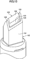
- FIG. 13 is an enlarged perspective view of a main part of FIG. 12
- FIG. 14 is a view. 12 is a vertical cross-sectional view.
- the writing tool 101 includes a pen tip 102 and a holding member 103 that holds the pen tip 102. and, The front portion 123 of the pen tip 102 extends in the axial direction, and The cross section of the front portion 123 of the pen tip 102 with respect to the extending direction has a substantially rectangular shape.
- the tip of the holding member 103 has a holding portion 131 that surrounds the front portion 123 of the pen tip 102.
- the holding portion 131 is provided with a notch-shaped opening 133 on both long sides of a substantially rectangular cross section of the front portion 123 of the pen tip 102.
- the top portion 122 of the pen tip 102 is formed in a substantially linear shape in a side view, and has an acute angle with respect to the extending direction of the front portion 123 of the pen tip 102.
- the trailing edge 134 of the opening 133 is formed substantially linearly in a side view and is parallel to the top 122 of the pen tip 102.
- the holding portion 131 is a pair of extensions extending in a direction substantially parallel to the extending direction of the front portion 123 of the pen tip 102 on both short sides of a substantially rectangular shape in the cross section of the front portion 123 of the pen tip 102. It has a piece 135.
- the notch-shaped opening 133 allows the pen tip 102 to bend and deform toward the long side during writing. As a result, the entire writing section comes into contact with the paper surface, and a constant line width can be reliably obtained. Further, the contact of the pair of extension pieces 135 with the paper surface can promote writing at the writing pressure as designed, and can prevent excessive bending (and thus damage) of the pen tip 102.
- Patent Document 2 has the above-mentioned advantages, but the inventor of the present invention has found the following improvements.
- the top 122 of the pen tip 102 is directed with respect to the extension direction of the front portion 123 (and the pair of extension pieces 135) of the pen tip 102. Since the pen tip 102 has a sharp angle, the direction A for bending the pen tip 102 (sinking into the paper surface) and the direction B for moving the pen tip 102 form a sharp angle (intersect in a plan view). As a result, it may not be easy to draw a straight line as intended.
- An object of the present invention is a writing tool in which the entire pen tip is tiltably supported so as to come into contact with the paper surface, and when drawing a straight line with a ruler and when drawing a straight line without using a ruler. Is to provide a writing tool that is relatively easy to draw a straight line as intended.
- the present invention With the pen tip A holding member that holds the pen tip and It is a stationery equipped with
- the front portion of the pen tip extends in a straight line direction that is inclined at an acute angle in the side view with respect to the axial direction.
- the cross section of the front portion of the pen tip with respect to the extension direction has a substantially rectangular shape.
- the holding member has a holding portion that surrounds at least a part of the front portion of the pen tip.
- the holding portion is provided with openings on both long sides of a substantially rectangular shape of the cross section of the front portion of the pen tip.
- the top of the pen tip is formed in a substantially linear shape in a side view, and is substantially perpendicular to the extension direction of the front portion of the pen tip.
- the trailing edge of the opening is formed in a substantially linear shape in a side view, and is substantially parallel to the top of the pen tip.
- the holding portion is a substantially rectangular short side of the cross section of the front portion of the pen tip, and is on the short side inward in a side view, in the extending direction of the front portion of the pen tip. It is a writing tool characterized by having an extension piece extending in a direction substantially parallel to the above.
- the extension piece extends in a direction substantially parallel to the extension direction of the front portion of the pen tip. Therefore, when drawing a straight line using a ruler, the extension piece can make line contact or surface contact with the ruler, and the pen tip is stable (see FIG. 7). Therefore, it becomes easy to draw a straight line as intended. Further, even when a straight line is drawn without using a ruler, the direction in which the pen tip is bent (sinked with respect to the paper surface) and the direction in which the pen tip is moved coincide with each other in a plan view (see FIG. 8). Therefore, it becomes easy to draw a straight line as intended.
- the holding portion extends in a direction substantially parallel to the extending direction of the front portion of the pen tip on both short sides of a substantially rectangular shape of the cross section of the front portion of the pen tip.
- the contact of the pair of extension pieces with the paper surface can more effectively promote writing at the pen pressure as designed, and more effectively prevent excessive bending (and thus damage) of the pen tip. Can be prevented.
- connection portion on the rear side of the front portion continuous with the front portion of the pen tip extends substantially in the axial direction.
- connection portion of the pen tip is provided with a diaphragm portion whose cross section changes with respect to the axial direction.
- the width of the opening is larger than the width on the long side of the substantially rectangular shape of the cross section of the front portion of the pen tip.
- the front part of the pen tip is not pressed against the inner surface of the extension piece at the time of writing, it can be more reliably bent and deformed to the long side side, and the entire pen tip is the paper surface regardless of the angle of the pen tip with respect to the paper surface. A constant line width is surely obtained.
- a shaft cylinder connected to the holding member is further provided, a rear portion of the holding member is attached to a front portion of the shaft cylinder, and a first contact wall is provided on the inner surface of the holding member.
- a second contact wall portion is formed on the inner surface of the barrel, and the outer surface of the pen tip is formed by the first contact wall portion and the second contact wall portion. It is sandwiched in the front-back direction.
- the pen tip is either a fiber pen tip, a felt-tip pen tip, a pen tip made of a porous body having open cells, or a plastic pen tip having an axial capillary passage.
- the pen tip can have the desired flexibility. Therefore, the pen tip can be flexed and deformed more reliably toward the long side, and the entire pen tip comes into contact with the paper surface regardless of the angle of the pen tip with respect to the paper surface, so that a constant line width can be reliably obtained.
- a chamfered portion is provided on the tip end portion of the front portion of the pen tip on a side inclined at an acute angle in a side view. According to this, it is possible to effectively suppress the defect or peeling at the tip portion on the side (inward side) inclined at an acute angle at the front portion of the pen tip.
- the fibers are arranged in the axial direction in the manufacturing process, so if the tip on the inner side of the front part of the pen tip is perpendicular, that part will be It becomes an aggregate of short fibers and becomes very brittle.
- the chamfered portion in the portion By providing the chamfered portion in the portion, the fibers constituting the portion become longer, so that the brittleness is remarkably reduced and the chipping and peeling can be effectively suppressed.
- the pen tip is a pen tip made of a porous body having open cells, if the tip on the inner side of the front portion of the pen tip is at a right angle, that portion becomes very fragile. Even in this case, by providing the chamfered portion in the portion, the brittleness of the portion is remarkably reduced, and the chipping and peeling can be effectively suppressed.
- the extension piece extends in a direction substantially parallel to the extension direction of the front portion of the pen tip. Therefore, when drawing a straight line using a ruler, the extension piece can make line contact or surface contact with the ruler, and the pen tip is stable (see FIG. 7). Therefore, it becomes easy to draw a straight line as intended. Further, even when a straight line is drawn without using a ruler, the direction in which the pen tip is bent (sinked with respect to the paper surface) and the direction in which the pen tip is moved coincide with each other in a plan view (see FIG. 8). Therefore, it becomes easy to draw a straight line as intended.
- FIG. 3A is a side view of the pen tip of FIG. 1
- FIG. 3B is a perspective view
- 4 (a) is a side view of the holding member of FIG. 1
- FIG. 4 (b) is a perspective view.
- It is a schematic side view of the state in which the pen tip of FIG. 3 is being inserted into the holding member of FIG. 6 (a) is a side view of a state in which the pen tip of FIG. 3 is inserted into the holding member of FIG. 4, and
- FIG. 6 (b) is a perspective view.
- FIG. 7A is a schematic perspective view
- FIG. 7B is a schematic front view
- FIG. 7 (a) c) is a schematic plan view.
- FIG. 8A is a schematic perspective view
- FIG. 8B is a schematic plan view.
- 9 (a) is a side view of a modified example of the pen tip
- FIG. 9 (b) is a perspective view. It is a side view of the modification of the holding member. It is a side view of the writing tool by patent document 2.
- FIG. It is an enlarged view of the main part of FIG.
- FIG. 12 is an enlarged perspective view of a main part of FIG. It is a vertical sectional view of FIG. It is explanatory drawing in the case of drawing a straight line with a ruler by the writing tool by Patent Document 2
- FIG. 15 (a) is a schematic perspective view
- FIG. 15 (b) is a schematic front view
- FIG. 15 ( c) is a schematic plan view.
- FIG. 16 (a) is a schematic perspective view
- FIG. 16 (b) is a schematic plan view
- FIG. 17A is a side view of the pen tip of the writing tool according to the second embodiment of the present invention
- FIG. 17B is a perspective view.
- FIG. 18 (a) is a side view of a holding member of a writing tool according to a third embodiment of the present invention
- FIG. 18 (b) is a perspective view. It is explanatory drawing in the case of drawing a straight line with a ruler by the writing tool according to 3rd Embodiment of this invention
- FIG. 19A is a schematic perspective view
- FIG. 19B is a schematic front view.
- .. 20 (a) is a side view of a holding member of a writing tool according to a fourth embodiment of the present invention
- FIG. 20 (b) is a perspective view. It is explanatory drawing in the case of drawing a straight line with a ruler by the writing tool according to 4th Embodiment of this invention, FIG.
- FIG. 21A is a schematic perspective view
- FIG. 21B is a schematic front view
- .. 22 (a) is a side view of the pen tip of the writing tool according to the fifth embodiment of the present invention
- FIG. 22 (b) is a perspective view.
- FIG. 1 is a vertical cross-sectional view showing a writing tool 1 according to the present embodiment
- FIG. 2 is an enlarged view of a main part of FIG. 1
- FIG. 3A is a side view of a pen tip 2 of FIG. 3 (b) is a perspective view of the pen tip 2 of FIG. 1
- FIG. 4 (a) is a side view of the holding member 3 of FIG. 1
- FIG. 4 (b) is a holding of FIG. It is a perspective view of a member.
- FIG. 5 is a schematic side view of a state in which the pen tip 2 of FIG. 3 is being inserted into the holding member 3 of FIG. 4
- FIG. 6A shows the holding of the pen tip 2 of FIG. 3 in FIG. It is a side view of the state inserted into the member 3, and
- FIG. 6B is a perspective view thereof.
- the writing tool 1 includes a pen tip 2 and a holding member 3 for holding the pen tip 2. Further, the writing tool 1 according to the present embodiment further includes an ink storage body 6 and a front shaft 4 and a rear shaft 5 in which the ink storage body 6 is housed. The holding member 3 is press-fitted to the front shaft 4.
- the pen tip 2 is composed of a fiber pen tip (resin processed body of a fiber bundle). However, the pen tip 2 may be any one as long as the ink can be distributed and has flexibility. Specifically, the pen tip 2 is a porous body of synthetic resin having open cells, a felt-tip pen tip, a brush pen tip, and an axial direction. Examples thereof include a plastic pen tip having a capillary passage.
- the front portion 23 of the pen tip 2 extends in a straight line direction inclined at an acute angle (30 ° in this embodiment) in the side view with respect to the axial direction.
- the cross section of the front portion 23 of the pen tip 2 with respect to the extending direction has a substantially rectangular shape (long side 4.5 mm, short side 1 to 3 mm).
- the extension length (length that maintains a substantially rectangular cross section) is 2.6 mm in this embodiment.
- the front portion 23 of the pen tip 2 is sandwiched (partially surrounded) by a pair of extension pieces 35 of the holding member 3 described later, and the top portion 22 of the pen tip 2 is the tip portion of the holding member 3. It slightly protrudes forward (diagonally forward) from.
- the top portion 22 of the pen tip 2 is formed in a substantially linear shape in a side view, and is perpendicular to the extending direction of the front portion 23 of the pen tip 2.
- the top portion 22 of the pen tip 2 has a convex curved surface-shaped R shape.
- the top 22 has an R shape in order to ensure that the top 22 is in contact with the paper surface.
- a notch 23d is provided in at least one of the front portion 23 or the connection portion 23b of the pen tip 2.
- the connecting portion 23b on the rear side of the front portion 23 continuous with the front portion 23 of the pen tip 2 extends substantially in the axial direction.
- the connection portion 23b is provided with a throttle portion 23c whose cross section changes with respect to the axial direction.
- the front end side of the squeezing portion 23c is continuous with the front portion 23 of the pen tip 2 (the cross section of the front portion 23 of the pen tip 2 with respect to the extending direction is substantially rectangular), and the rear end side of the squeezing portion 23c is It has a substantially square columnar shape (the cross section in the axial direction is approximately rectangular). That is, the connecting portion 23b on the rear side of the front portion 23 has a substantially rectangular cross section.
- the drawing portion 23c is at least a part of the notch 23d, and the drawing portion 23c can also be easily processed by grinding, punching, or the like.
- a cylindrical (large diameter) central portion 24 whose outer surface is sandwiched in the front-rear direction by the holding member 3 and the front shaft 4, and the front end of the ink storage body 6.
- the holding member 3 is a tubular body obtained by injection molding of a synthetic resin with both ends opened. As shown in FIGS. 3 to 6, the pen tip 2 is fitted (locked to prevent it from coming off in the axial direction) from the rear side in the holding member 3.
- a plurality of (here, four) inner surface ribs extending in the axial direction into which the central portion 24 of the pen tip 2 is press-fitted are formed at equal intervals on the inner surface having a circular cross-sectional shape at the rear end of the holding member 3.
- a plurality of (6 in this case) outer surface ribs extending in the axial direction to be press-fitted to the front shaft 4 are formed at equal intervals on the outer surface having a circular cross-sectional shape at the rear end of the holding member 3. .
- the outer surface of the holding member fitting portion of the front shaft 4 has a circular cross-sectional shape. A reliable airtight fit between the inner surface of the cap and the outer surface of the front shaft 4 can be obtained.
- the communication hole formed by the outer surface rib and the front shaft 4 functions as an air flow hole, and enables smooth ink ejection from the pen tip 2.
- the holding member 3 has a holding portion 31 having a substantially rectangular cross section that substantially surrounds the front portion 23 and the connecting portion 23b of the pen tip 2. Since the connection portion 23b of the pen tip 2 described above has a substantially rectangular cross section and the holding portion 31 of the holding member 3 has a substantially rectangular cross section, the pen tip 2 is inserted into the holding member 3. It is a guide that can be aligned in the rotation direction (circumferential direction) when assembling. As a result, the directions of the pen tip 2 and the holding member 3 in the rotation direction can be easily aligned.
- a notch-shaped opening 33 is provided on both long sides of the substantially rectangular shape of the cross section of the front portion 23 of the pen tip 2.
- the width of the opening 33 is larger than the width of the long side of the substantially rectangular cross section of the front portion 23 of the pen tip 2.
- the pen tip 2 When not writing, the pen tip 2 is located on the axis of the writing tool 1. On the other hand, at the time of writing, the pen tip 2 can be bent and deformed toward the opening 33 side (long side side) and deviated from the axis of the writing tool 1. As a result, the entire top 22 of the pen tip 2 can come into contact with the paper surface regardless of the angle between the axis of the writing tool 1 and the paper surface, and a constant line width can be reliably obtained at all times.
- the top portion 22 of the pen tip 2 is formed substantially linearly in a side view, extends in a direction perpendicular to the extending direction of the front portion 23 of the pen tip 2, and is the rear end of the opening 33.
- the edge portion 34 is also formed in a substantially linear shape in a side view, and extends in a direction parallel to the top portion 22 of the pen tip 2.
- the shape of the side view of the pen tip 2 exposed from the holding member 3 is rectangular, the direction of the pen tip 2 can be grasped by the direction of the rear end edge portion 34. Therefore, after exposing the pen tip 2, it can be used for writing immediately.
- an embodiment in which the opening 33 is provided only on the side wall on one side of the holding portion 31 is also an aspect of the present invention.
- the openings 33 are provided on both side walls, the desired bending effect can always be exhibited regardless of whether the user is right-handed or left-handed, which is excellent in convenience.
- the holding portion 31 of the present embodiment is anterior to the rear end edge portion 34 of the opening 33 (rear end edge portion 34) on both short sides of the substantially rectangular shape of the cross section of the front portion 23 of the pen tip 2. It has a pair of extension pieces 35 (inner extension piece 35a and outer extension piece 35b) protruding in the vertical direction of the above.
- the pair of extension pieces 35 extend in a direction parallel to the extension direction of the front portion 23 of the pen tip 2, and come into contact with the paper surface during writing.
- each of the pair of extension pieces 35 is tapered toward the front (vertical direction of the rear end edge portion 34), and a convex curved surface is formed at the front end thereof.
- the inner extension pieces 35 can make line contact or surface contact with the ruler or the like.
- the pen tip 2 is stable (see FIG. 7). Therefore, it is easy to draw a line as intended. Further, since the pen tip 2 does not come into contact with the ruler or the like, it is possible to prevent the ruler or the like from being soiled by ink, and conversely, the handwriting at the time of writing due to the dirt adhering to the ruler or the like being transferred to the pen tip 2. You can also prevent dirt.
- the holding member 3 has a pair of extension pieces 35, when the pen tip 2 is inserted into the cap or the like of the writing tool 1, the pen tip 2 comes into contact with the inner surface of the cap to prevent ink from adhering to the inner surface of the cap. Can be prevented.
- the ink adheres to the inner surface of the cap the ink adhered to the inner surface of the cap may be transferred and adhered to the outer surface of the front shaft 4 when the cap is fitted to the writing tool 1.
- the user removes the cap again and grips the front shaft 4 of the writing tool 1, there is a risk that the hand will be soiled with ink.
- the holding member 3 has the inward extending piece 35a, the inward extending piece 35a and the step formed by the front portion 23 of the pen tip and the notch 23d (throttle portion 23c) are in the axial direction. It is locked to prevent it from coming off. As a result, more stable fitting of the pen tip 2 and the holding member 3 can be realized.
- the top portion 22 of the pen tip 2 protrudes from the tips of the pair of extension pieces 35 in the extension direction, and the amount of protrusion thereof is larger than 0.2 mm and smaller than 5.0 mm, preferably 0.5 mm or more. It is effective that it is large and smaller than 2.0 mm. The smaller the amount of protrusion within the preferred range, the more rigid and firm the brush feeling is obtained, and the larger the amount of protrusion within the preferred range, the softer the brush feeling is obtained.
- the rear end edge portion 34 is provided with a chamfer or R.
- chamfering or R is provided at least on the edge on the pen tip 2 side where the pen tip 2 may come into contact.
- a mode in which the extension piece 35 is provided only on the inner short side in a side view is also an aspect of the present invention.
- the color of the holding member 3 is different from the color of the pen tip 2 (that is, the ink color).
- the orientation of the rear end edge portion 34 becomes more conspicuous, and it becomes easier to confirm the orientation of the pen tip 2.
- the direction of the trailing end edge portion 34 becomes more conspicuous, and the pen tip 2 becomes more prominent. It becomes easier to check the shape.
- the holding member 3 may be entirely made of a transparent material or a translucent material. In this case, the color of the ink becomes easy to see. In addition, it is possible to provide an excellent form in terms of design (aesthetics).
- the region near the front end of the holding member 3 may be colored, and the rest may be made of a transparent material or a translucent material.
- This aspect has an effect of facilitating grasping the relative position between the writing instrument and the writing object when the color of the writing object (for example, the paper surface) and the color of the ink are similar.
- the front shaft 4 is a tubular body obtained by injection molding or extrusion molding of a synthetic resin with both ends open. As shown in FIGS. 1 and 2, the outer surface (outer surface rib) of the rear end portion of the holding member 3 is press-fitted to the inner surface of the front end portion of the front shaft 4.
- a plurality of (here, eight) vertical ribs 43 extending in the axial direction are integrally formed at equal intervals.
- the central portion 24 of the pen tip 2 is sandwiched in the front-rear direction by the first contact wall portion 36 of the holding member 3 and the second contact wall portion 41 at the front end of the vertical rib 43.
- the pen tip 2 is prevented from falling off from the holding member 3 or being buried in the holding member 3 (front shaft 4), and accurately regulate the amount of protrusion of the pen tip 2 from the holding member 3. be able to.
- the front end portion of the ink storage body 6 is sandwiched in the front-rear direction between the third contact wall portion 42 at the rear end of the vertical rib 43 and the bottom wall of the shaft cylinder 5 described later.
- the rear shaft 5 connected to the rear end of the front shaft 4 is a cylindrical bottomed cylinder composed of a bottom wall and a peripheral wall, the front end being opened and the rear end being closed, and a synthetic resin (for example, for example). Obtained by injection molding of polypropylene, etc.).
- the front shaft 4 is airtightly fitted to the rear shaft 5 by screwing or press fitting.
- the ink storage body 6 is made of a member having continuous pores capable of impregnating ink.
- a heat-sealed body of a fiber bundle a resin processed body of a fiber bundle, a resin processed body of a felt, a needle punched body of a felt, a porous body (for example, an open cell of a synthetic resin such as a sponge), etc.
- the ink storage body 6 may have an outer skin made of a synthetic resin film or the like on the outer peripheral surface thereof.
- the writing instrument 1 having the above configuration can exert the following effects. That is, according to the writing tool 1 of the present embodiment, since the extension piece 35 extends in a direction substantially parallel to the extension direction of the front portion 23 of the pen tip 2, when drawing a line using a ruler, The extension piece 35 can make line contact or surface contact with the ruler, and the pen tip 2 is stable (see FIG. 7). Therefore, it becomes easy to draw a line as intended.
- the direction A for bending the pen tip 2 (sinking into the paper surface) and the direction B for moving the pen tip 2 even when drawing a line without using a ruler. Matches in a plan view (see FIG. 8). Therefore, it becomes easy to draw a line as intended.
- the holding portion 31 of the writing tool 1 of the present embodiment is substantially parallel to the extending direction of the front portion 23 of the pen tip 2 on both short sides of the substantially rectangular shape of the cross section of the front portion 23 of the pen tip 2. It has a pair of extension pieces 35 extending in various directions. Therefore, the contact of the pair of extension pieces 35 with the paper surface can more effectively promote writing at the writing pressure as designed, and further prevent excessive bending (and thus damage) of the pen tip 2. It can be effectively prevented.
- the connecting portion 23b on the rear side of the front portion 23 continuous with the front portion 23 of the pen tip 2 extends substantially in the axial direction.
- the connecting portion 23b of the pen tip 2 is provided with a diaphragm portion 23c whose cross section changes with respect to the axial direction. This can facilitate the work of inserting the pen tip 2 into the holding member 3 (see FIG. 5).
- the throttle portion 23c is not provided is also an aspect of the present invention. That is, as shown in FIG. 9A, the pen tip 2'may have a constant cross section with respect to the axial direction in the entire connecting portion 23b'.
- the holding member 3'corresponding to this has a form as shown in FIG.
- the top portion 22 of the pen tip 2' may have a rectangular writing surface. This makes it easier to process the shape of the top 22 of the pen tip 2'.
- the width of the opening 33 is larger than the width on the long side of the substantially rectangular shape of the cross section of the front portion 23 of the pen tip 2.
- the front shaft 4 connected to the holding member 3 is further provided, the rear portion of the holding member 3 is attached to the front portion of the front shaft 4, and the inner surface of the holding member 3 is provided.
- a first contact wall portion 36 is formed in the front shaft 4, and a second contact wall portion 51 is formed on the inner surface of the front shaft 4.
- the first contact wall portion 36 and the second contact wall portion 41 form a second contact wall portion 51.
- the outer surface of the pen tip 2 is sandwiched in the front-rear direction. This makes it possible to effectively prevent the pen tip 2 from falling off from the holding member 3 or burying the pen tip 2 in the holding member 3, and further, the amount of protrusion of the pen tip 2 from the holding member 3 can be prevented. Can be maintained accurately.
- the pen tip 2 is either a fiber pen tip (resin processed body of a fiber bundle), a felt-tip pen tip, a pen tip made of a porous body having open cells, or a plastic pen tip having an axial capillary passage. Is it? According to this, the pen tip 2 can have the desired flexibility. Therefore, the pen tip 2 can be flexed and deformed more reliably toward the long side, and the entire pen tip 2 comes into contact with the paper surface regardless of the angle of the pen tip 2 with respect to the paper surface, so that a constant line width can be reliably obtained.
- FIG. 17A is a side view of the pen tip 202 of the writing tool according to the second embodiment of the present invention
- FIG. 17B is a perspective view of the pen tip 202.
- the pen tip 202 of the second embodiment has a plate-shaped substantially rectangular parallelepiped shape in the front portion 223 due to the provision of the notch 223d.
- the top 222 is a flat surface and is not provided with a convex curved R shape.
- the front portion 223 of the pen tip 202 extends in a linear direction inclined at an acute angle (30 ° in this embodiment) in the side view with respect to the axial direction, substantially similar to the front portion 23 of the pen tip 2 of the above-described embodiment. It is out.
- the cross section of the front portion 223 of the pen tip 202 with respect to the extending direction has a substantially rectangular shape (long side 4.5 mm, short side (thickness) 1.5 mm).
- the extension length (length that maintains a substantially rectangular cross section) is 2.5 mm in this embodiment.
- the front portion 223 of the pen tip 202 is sandwiched (partially surrounded) by a pair of extension pieces of the corresponding holding member (not shown), and the top 222 of the pen tip 202 is the tip of the holding member. It slightly protrudes forward (diagonally forward) from the part.
- the top portion 222 of the pen tip 202 is formed in a substantially linear shape in a side view, and is perpendicular to the extending direction of the front portion 223 of the pen tip 202.
- the top 222 of the pen tip 202 does not have a convex curved R shape and has a flat surface, the top 222 is compared with the top 22 of the pen tip 2 of the above-described embodiment. , The contact area with the paper surface is small at the time of writing. As a result, when the pen tip 202 is separated from the paper surface after writing is finished, the degree of "ink pool" that may be formed on the paper surface is suppressed.
- the notch 223d is provided on the side where the front portion 223 of the pen tip 202 is inclined at an acute angle in the side view with respect to the axial direction so that the front portion 223 of the pen tip 202 has a substantially rectangular parallelepiped shape.
- the front end of the notch 223d is located slightly behind the top 222, so that the front portion 223 of the pen tip 202 is complete.
- the position of the front end of the notch 223d may be aligned with the top portion 222, and the front portion 223 of the pen tip 202 may have a perfect rectangular parallelepiped shape.
- the connection portion 223b of the present embodiment has a plate shape having the same thickness as the front portion 223, but has a throttle portion 223c whose cross section changes with respect to the axial direction, and a throttle portion 223c extending rearward from the rear end of the throttle portion 223c and gradually extending to the rear side.
- Both the line and the boundary line between the transition portion 223e and the rear portion 223f are parallel to the top portion 222.
- the change in the cross section of the throttle portion 223c with respect to the axial direction can be relatively easily processed into a desired shape by forming the notch 223d by grinding, punching, or the like.
- the cross section by the surface including the boundary line between the narrowing portion 223c and the transition portion 223e has a substantially rectangular shape (long side 5.8 mm, long side 5.8 mm, The short side (thickness) is 1.5 mm), and the cross section formed by the surface including the boundary line between the transition portion 223e and the rear portion 223f is substantially rectangular (long side 5.8 mm, short side (thickness) 3). .2 mm).
- the outer surface is sandwiched in the front-rear direction by the holding member and the front shaft 4 (cylindrical shape).
- a central portion 224 (large diameter) and a cylindrical (small diameter) rear end portion 225 connected to the front end portion of the ink storage body 6 in a piercing manner are provided.
- the narrowing portion 223c of the connecting portion 223b has a plate shape having the same thickness as the front portion 223, and is between the narrowing portion 223c and the transition portion 223e. Because the border is parallel to the top 222 (and the border between the transition 223e and the rear 223f is also parallel to the top 222), the pen tip 202 is at the time of writing. It can be bent more flexibly. Therefore, even if the pen tip 202 has an undesired dimensional variation (especially if it is too long in the axial direction), the risk of damage to the pen tip 202 during writing is significantly suppressed. obtain.
- the pen tip 202 is also made of a fiber pen tip (resin processed body of a fiber bundle).
- the pen tip 202 may also be a pen tip 202 as long as the ink can be distributed and has flexibility.
- a porous body of synthetic resin having open cells a felt-tip pen tip, a brush pen tip, and an axial capillary passage.
- a plastic pen tip having a pen tip, etc. may be mentioned.
- FIG. 18A is a side view of the holding member 303 of the writing tool according to the third embodiment of the present invention
- FIG. 18B is a perspective view of the holding member 303.
- FIG. 19A is a schematic perspective view when a straight line is drawn using a ruler with the writing tool according to the present embodiment
- FIG. 19B is a schematic front view thereof.
- the holding portion 331 of the holding member 303 of the present embodiment is substantially the same as the embodiment described with reference to FIGS. 4 (a) to 6 (b).
- a pair of extensions protruding forward from the rear end edge portion 334 of the opening 333 (in the vertical direction of the rear end edge portion 334). It has a piece (inner extension piece 335a and outer extension piece 335b).
- the pair of extension pieces 335a and 335b extend in a direction parallel to the extension direction of the front portion 23 of the pen tip 2, and come into contact with the paper surface during writing.
- each of the pair of extension pieces 335a and 335b is chamfered by, for example, about 45 ° to form a semi-partially inclined surface 335c of a truncated conical surface.
- the area where each extension piece 335a, 335b and the paper surface come into contact with each other at the time of writing is reduced (for example, only the width of about 0.2 mm is substantially arcuate (FIG. 19 (a)). ),
- the pressure applied to the paper surface from the extension pieces 335a and 335b becomes stronger, and the extension pieces 335a and 335b are more likely to bite into the paper surface. As a result, it is possible to more effectively prevent the handwriting from shifting in an unintended direction.
- FIGS. 19 (a) and 19 (b) when drawing a line on a paper surface using a ruler or the like, it is even easier to draw the line as intended.
- FIG. 20 (a) is a side view of the holding member 403 of the writing tool according to the fourth embodiment of the present invention
- FIG. 20 (b) is a perspective view of the holding member 403.
- 21 (a) is a schematic perspective view of a case where a straight line is drawn using a ruler with a writing tool according to the present embodiment
- FIG. 21 (b) is a schematic front view thereof.
- the holding portion 431 of the holding member 403 of the present embodiment is substantially the same as the embodiment described with reference to FIGS. 4 (a) to 6 (b).
- a pair of extensions protruding forward from the rear end edge portion 434 of the opening 433 (in the vertical direction of the rear end edge portion 434). It has a piece (inner extension piece 435a and outer extension piece 435b).
- the pair of extension pieces 435a and 435b extend in a direction parallel to the extension direction of the front portion 23 of the pen tip 2, and come into contact with the paper surface during writing.
- each of the pair of extension pieces 435a and 435b is chamfered by a plurality of (five in the illustrated example) inclined planes 435c.
- a plurality of inclined planes 435c By providing such a plurality of inclined planes 435c, the area where each extension piece 435a, 435b and the paper surface come into contact with each other at the time of writing is reduced (for example, only the width of about 0.1 mm has a length of about 1.4 mm). (See FIG. 21 (a)), the pressure applied to the paper surface from the extension pieces 435a and 435b becomes stronger, and the extension pieces 435a and 435b can easily bite into the paper surface. As a result, it is possible to more effectively prevent the handwriting from shifting in an unintended direction.
- FIGS. 21 (a) and 21 (b) when drawing a line on a paper surface using a ruler or the like, it is even easier to draw the line as intended.
- FIG. 22 (a) is a side view of the pen tip 502 of the writing tool according to the fifth embodiment of the present invention
- FIG. 22 (b) is a perspective view of the pen tip 502.
- the front portion 523 of the pen tip 502 extends in a linear direction inclined at an acute angle (30 ° in this embodiment) in the side view with respect to the axial direction, substantially similar to the front portion 23 of the pen tip 2 of the above-described embodiment. It is out.
- the cross section of the front portion 523 of the pen tip 502 with respect to the extending direction has a substantially rectangular shape (long side 5.0 mm, short side 1 to 3.2 mm).
- the extension length (the length that maintains a substantially rectangular cross section) is 2.6 mm in this embodiment.
- the front portion 523 of the pen tip 502 is sandwiched (partially surrounded) by a pair of extension pieces of the corresponding holding member (not shown), and the top 522 of the pen tip 502 is the tip of the holding member. It slightly protrudes forward (diagonally forward) from the part.
- the top portion 522 of the pen tip 502 is formed in a substantially linear shape in a side view, and is perpendicular to the extending direction of the front portion 523 of the pen tip 502.
- the front portion 523 of the pen tip 502 has a shape in which the thickness decreases toward the top portion 522 side, but the top portion 522 of the pen tip 502 does not have a convex curved R shape. , It is a flat surface. Therefore, the top portion 522 has a smaller contact area with the paper surface at the time of writing than the top portion 22 of the pen tip 2 of the above-described embodiment. This suppresses the degree of "ink pool" that may be formed on the paper surface when the pen tip 502 is separated from the paper surface after writing is completed.
- the notch 523d is provided on the side where the front portion 523 of the pen tip 502 is inclined at an acute angle in the side view with respect to the axial direction so that the front portion 523 of the pen tip 502 has a substantially rectangular parallelepiped shape.
- the front end of the notch 523d is located 1.3 mm behind the inner end of the top 522, and the front end 523 of the pen tip 502 has a perfect rectangular parallelepiped shape. do not have. That is, the chamfered portion 522d is provided on the side (inward side) inclined at an acute angle in the side view of the tip portion of the front portion 523 of the pen tip 502.
- the pen tip 502 is a pen tip made of a porous body having open cells, if the tip on the inner side of the front portion 523 of the pen tip 502 is at a right angle, that portion becomes very fragile. .. Even in this case, by providing the chamfered portion 522d in the portion, the brittleness of the portion is remarkably reduced, and chipping and peeling can be effectively suppressed.
- the connecting portion 523b on the rear side of the front portion 523 which is continuous with the front portion 523 of the pen tip 502, extends substantially in the axial direction.
- the connection portion 523b is provided with a throttle portion 523c whose cross section changes with respect to the axial direction.
- the front end side of the squeezing portion 523c is continuous with the front portion 523 of the pen tip 502 (the cross section of the front portion 523 of the pen tip 502 with respect to the extending direction is substantially rectangular), and the rear end side of the squeezing portion 523c is It is continuous with the rear portion 523f of a substantially square columnar shape (the cross section in the axial direction is substantially rectangular).
- the change in the cross section of the drawn portion 523c with respect to the axial direction can be relatively easily processed into a desired shape by forming the notch 523d by grinding, punching, or the like.
- the outer surface is sandwiched in the front-rear direction by the holding member and the front shaft 4 (cylindrical shape).
- a central portion 524 (large diameter) and a cylindrical (small diameter) rear end portion 525 connected to the front end portion of the ink storage body 6 in a piercing manner are provided.
- the pen tip 502 is not limited to a fiber pen tip (resin processed body of a fiber bundle) or a porous body of synthetic resin having open cells, and is a felt-tip pen tip, a brush pen tip, and a plastic having an axial capillary passage. It may be a pen tip, etc.
Landscapes
- Pens And Brushes (AREA)
Priority Applications (2)
| Application Number | Priority Date | Filing Date | Title |
|---|---|---|---|
| CN202190000944.2U CN220314575U (zh) | 2020-12-24 | 2021-12-20 | 书写工具 |
| JP2022571429A JPWO2022138534A1 (zh) | 2020-12-24 | 2021-12-20 |
Applications Claiming Priority (2)
| Application Number | Priority Date | Filing Date | Title |
|---|---|---|---|
| JP2020214418 | 2020-12-24 | ||
| JP2020-214418 | 2020-12-24 |
Publications (1)
| Publication Number | Publication Date |
|---|---|
| WO2022138534A1 true WO2022138534A1 (ja) | 2022-06-30 |
Family
ID=82157901
Family Applications (1)
| Application Number | Title | Priority Date | Filing Date |
|---|---|---|---|
| PCT/JP2021/046939 WO2022138534A1 (ja) | 2020-12-24 | 2021-12-20 | 筆記具 |
Country Status (4)
| Country | Link |
|---|---|
| JP (1) | JPWO2022138534A1 (zh) |
| CN (1) | CN220314575U (zh) |
| TW (1) | TW202229024A (zh) |
| WO (1) | WO2022138534A1 (zh) |
Citations (4)
| Publication number | Priority date | Publication date | Assignee | Title |
|---|---|---|---|---|
| JPS608085U (ja) * | 1983-06-29 | 1985-01-21 | ぺんてる株式会社 | セラミツク製ペン先 |
| US20020076254A1 (en) * | 2000-12-01 | 2002-06-20 | John Calabro | Doublet applicator device |
| WO2019230693A1 (ja) * | 2018-05-28 | 2019-12-05 | 三菱鉛筆株式会社 | 筆記具 |
| JP2020196166A (ja) * | 2019-05-31 | 2020-12-10 | 株式会社トンボ鉛筆 | 筆記具 |
-
2021
- 2021-12-20 WO PCT/JP2021/046939 patent/WO2022138534A1/ja active Application Filing
- 2021-12-20 JP JP2022571429A patent/JPWO2022138534A1/ja active Pending
- 2021-12-20 CN CN202190000944.2U patent/CN220314575U/zh active Active
- 2021-12-21 TW TW110147960A patent/TW202229024A/zh unknown
Patent Citations (4)
| Publication number | Priority date | Publication date | Assignee | Title |
|---|---|---|---|---|
| JPS608085U (ja) * | 1983-06-29 | 1985-01-21 | ぺんてる株式会社 | セラミツク製ペン先 |
| US20020076254A1 (en) * | 2000-12-01 | 2002-06-20 | John Calabro | Doublet applicator device |
| WO2019230693A1 (ja) * | 2018-05-28 | 2019-12-05 | 三菱鉛筆株式会社 | 筆記具 |
| JP2020196166A (ja) * | 2019-05-31 | 2020-12-10 | 株式会社トンボ鉛筆 | 筆記具 |
Also Published As
| Publication number | Publication date |
|---|---|
| JPWO2022138534A1 (zh) | 2022-06-30 |
| CN220314575U (zh) | 2024-01-09 |
| TW202229024A (zh) | 2022-08-01 |
Similar Documents
| Publication | Publication Date | Title |
|---|---|---|
| JP7275359B2 (ja) | 筆記具 | |
| US20060165470A1 (en) | Connector systems and marker systems comprising same | |
| US5820285A (en) | Pen nib | |
| WO2022138534A1 (ja) | 筆記具 | |
| EP0625378A2 (en) | Liquid applicator and method of making same | |
| JP2017144581A (ja) | 筆記具 | |
| JP6655386B2 (ja) | 筆記具 | |
| US6244775B1 (en) | Writing implement | |
| JP6915962B2 (ja) | 筆記具 | |
| JP2005324336A (ja) | インキタンク交換式筆記具 | |
| JP7080077B2 (ja) | 筆記具 | |
| CN210881415U (zh) | 书写工具和笔尖 | |
| JP3841936B2 (ja) | 筆記具 | |
| GB2041834A (en) | Nib for a writing instrument | |
| JP7538843B2 (ja) | 筆記具 | |
| JP6808472B2 (ja) | 筆記具 | |
| TWI827627B (zh) | 筆記具 | |
| JP4149052B2 (ja) | ノック式筆記具 | |
| US20230406029A1 (en) | Fiber-bundled part for writing instruments, and pen tip and writing instrument using the fiber-bundled part | |
| CN114286754B (zh) | 书写工具 | |
| JP3734529B2 (ja) | ペン先保持構造 | |
| JPH0578592U (ja) | 筆記用器具 | |
| JP2554726Y2 (ja) | 自動製図機用ペン | |
| CN115666963A (zh) | 书写工具和相关联的笔尖组件 | |
| JP4326812B2 (ja) | ペン先取付構造 |
Legal Events
| Date | Code | Title | Description |
|---|---|---|---|
| 121 | Ep: the epo has been informed by wipo that ep was designated in this application |
Ref document number: 21910679 Country of ref document: EP Kind code of ref document: A1 |
|
| ENP | Entry into the national phase |
Ref document number: 2022571429 Country of ref document: JP Kind code of ref document: A |
|
| WWE | Wipo information: entry into national phase |
Ref document number: 202190000944.2 Country of ref document: CN |
|
| NENP | Non-entry into the national phase |
Ref country code: DE |
|
| 122 | Ep: pct application non-entry in european phase |
Ref document number: 21910679 Country of ref document: EP Kind code of ref document: A1 |