WO2022138338A1 - 数値制御装置、数値制御システム及び消音方法 - Google Patents
数値制御装置、数値制御システム及び消音方法 Download PDFInfo
- Publication number
- WO2022138338A1 WO2022138338A1 PCT/JP2021/046109 JP2021046109W WO2022138338A1 WO 2022138338 A1 WO2022138338 A1 WO 2022138338A1 JP 2021046109 W JP2021046109 W JP 2021046109W WO 2022138338 A1 WO2022138338 A1 WO 2022138338A1
- Authority
- WO
- WIPO (PCT)
- Prior art keywords
- muffling
- sound
- data
- information
- numerical control
- Prior art date
- Legal status (The legal status is an assumption and is not a legal conclusion. Google has not performed a legal analysis and makes no representation as to the accuracy of the status listed.)
- Ceased
Links
Images






Classifications
-
- G—PHYSICS
- G05—CONTROLLING; REGULATING
- G05B—CONTROL OR REGULATING SYSTEMS IN GENERAL; FUNCTIONAL ELEMENTS OF SUCH SYSTEMS; MONITORING OR TESTING ARRANGEMENTS FOR SUCH SYSTEMS OR ELEMENTS
- G05B19/00—Program-control systems
- G05B19/02—Program-control systems electric
- G05B19/18—Numerical control [NC], i.e. automatically operating machines, in particular machine tools, e.g. in a manufacturing environment, so as to execute positioning, movement or co-ordinated operations by means of program data in numerical form
- G05B19/4155—Numerical control [NC], i.e. automatically operating machines, in particular machine tools, e.g. in a manufacturing environment, so as to execute positioning, movement or co-ordinated operations by means of program data in numerical form characterised by program execution, i.e. part program or machine function execution, e.g. selection of a program
-
- G—PHYSICS
- G10—MUSICAL INSTRUMENTS; ACOUSTICS
- G10K—SOUND-PRODUCING DEVICES; METHODS OR DEVICES FOR PROTECTING AGAINST, OR FOR DAMPING, NOISE OR OTHER ACOUSTIC WAVES IN GENERAL; ACOUSTICS NOT OTHERWISE PROVIDED FOR
- G10K11/00—Methods or devices for transmitting, conducting or directing sound in general; Methods or devices for protecting against, or for damping, noise or other acoustic waves in general
- G10K11/16—Methods or devices for protecting against, or for damping, noise or other acoustic waves in general
- G10K11/175—Methods or devices for protecting against, or for damping, noise or other acoustic waves in general using interference effects; Masking sound
- G10K11/178—Methods or devices for protecting against, or for damping, noise or other acoustic waves in general using interference effects; Masking sound by electro-acoustically regenerating the original acoustic waves in anti-phase
- G10K11/1781—Methods or devices for protecting against, or for damping, noise or other acoustic waves in general using interference effects; Masking sound by electro-acoustically regenerating the original acoustic waves in anti-phase characterised by the analysis of input or output signals, e.g. frequency range, modes, transfer functions
- G10K11/17821—Methods or devices for protecting against, or for damping, noise or other acoustic waves in general using interference effects; Masking sound by electro-acoustically regenerating the original acoustic waves in anti-phase characterised by the analysis of input or output signals, e.g. frequency range, modes, transfer functions characterised by the analysis of the input signals only
-
- G—PHYSICS
- G10—MUSICAL INSTRUMENTS; ACOUSTICS
- G10K—SOUND-PRODUCING DEVICES; METHODS OR DEVICES FOR PROTECTING AGAINST, OR FOR DAMPING, NOISE OR OTHER ACOUSTIC WAVES IN GENERAL; ACOUSTICS NOT OTHERWISE PROVIDED FOR
- G10K11/00—Methods or devices for transmitting, conducting or directing sound in general; Methods or devices for protecting against, or for damping, noise or other acoustic waves in general
- G10K11/16—Methods or devices for protecting against, or for damping, noise or other acoustic waves in general
- G10K11/175—Methods or devices for protecting against, or for damping, noise or other acoustic waves in general using interference effects; Masking sound
- G10K11/178—Methods or devices for protecting against, or for damping, noise or other acoustic waves in general using interference effects; Masking sound by electro-acoustically regenerating the original acoustic waves in anti-phase
- G10K11/1787—General system configurations
- G10K11/17879—General system configurations using both a reference signal and an error signal
- G10K11/17881—General system configurations using both a reference signal and an error signal the reference signal being an acoustic signal, e.g. recorded with a microphone
-
- G—PHYSICS
- G05—CONTROLLING; REGULATING
- G05B—CONTROL OR REGULATING SYSTEMS IN GENERAL; FUNCTIONAL ELEMENTS OF SUCH SYSTEMS; MONITORING OR TESTING ARRANGEMENTS FOR SUCH SYSTEMS OR ELEMENTS
- G05B2219/00—Program-control systems
- G05B2219/30—Nc systems
- G05B2219/34—Director, elements to supervisory
- G05B2219/34013—Servocontroller
-
- G—PHYSICS
- G10—MUSICAL INSTRUMENTS; ACOUSTICS
- G10K—SOUND-PRODUCING DEVICES; METHODS OR DEVICES FOR PROTECTING AGAINST, OR FOR DAMPING, NOISE OR OTHER ACOUSTIC WAVES IN GENERAL; ACOUSTICS NOT OTHERWISE PROVIDED FOR
- G10K2210/00—Details of active noise control [ANC] covered by G10K11/178 but not provided for in any of its subgroups
- G10K2210/10—Applications
- G10K2210/105—Appliances, e.g. washing machines or dishwashers
-
- G—PHYSICS
- G10—MUSICAL INSTRUMENTS; ACOUSTICS
- G10K—SOUND-PRODUCING DEVICES; METHODS OR DEVICES FOR PROTECTING AGAINST, OR FOR DAMPING, NOISE OR OTHER ACOUSTIC WAVES IN GENERAL; ACOUSTICS NOT OTHERWISE PROVIDED FOR
- G10K2210/00—Details of active noise control [ANC] covered by G10K11/178 but not provided for in any of its subgroups
- G10K2210/30—Means
- G10K2210/301—Computational
- G10K2210/3033—Information contained in memory, e.g. stored signals or transfer functions
-
- G—PHYSICS
- G10—MUSICAL INSTRUMENTS; ACOUSTICS
- G10K—SOUND-PRODUCING DEVICES; METHODS OR DEVICES FOR PROTECTING AGAINST, OR FOR DAMPING, NOISE OR OTHER ACOUSTIC WAVES IN GENERAL; ACOUSTICS NOT OTHERWISE PROVIDED FOR
- G10K2210/00—Details of active noise control [ANC] covered by G10K11/178 but not provided for in any of its subgroups
- G10K2210/30—Means
- G10K2210/301—Computational
- G10K2210/3052—Simulation
Definitions
- the present invention is a numerical control device, a numerical control system, and a muffling method having a function of muffling the noise of a machine tool, a robot, or an industrial machine that generates noise during operation by generating a sound having a phase opposite to the noise. Regarding.
- Machine tools may generate noise during machining, etc., and it is required to suppress this noise. Since the sound generated during processing differs depending on the NC program (Numerically Controlled Program) or the material of the workpiece, it is difficult to predict what kind of sound will be generated without actually processing. There are measures such as installing a soundproof wall or covering the machine with a soundproof cover against the generation of noise, but this measure has a problem in terms of cost or installation area.
- Patent Document 1 and Patent Document 2 describe a device that detects noise and generates a sound having a phase opposite to the noise to mute the noise in order to suppress the noise generated from the machine tool.
- Patent Document 1 describes an active muffling device for an NC machine tool whose operation is controlled by a control command output by the NC machine tool by executing a machining program, and the NC machine tool is decoded by decoding the machining program executed by the NC machine tool.
- the generation timing of the generated noise is detected, and based on this detection timing and the residual sound detected by the residual sound detection microphone, the sound of the opposite phase to the noise is output in synchronization with the noise generation timing, and the sound is muted by sound interference.
- the machine tool device detects the driving sound, cooling sound, cutting sound, grinding sound, etc. generated when the machine tool is operated by the first pressure detector, and reverses based on this signal. It is described that the phase signal is calculated by a calculation device, and the antiphase sound is generated from the muffling speaker provided in the machine tool to mute each noise.
- Patent Document 3 describes an information system capable of canceling an operating sound by selecting canceling sound data with respect to an operating sound emitted from a peripheral device externally attached to a device having a voice output function.
- the information processing device in an information system in which an information processing device and a peripheral device separate from the information processing device are interfaced, the information processing device is specified by a device specifying unit for specifying the peripheral device and a device specifying unit. It is described that the peripheral device is provided with a data acquisition unit for acquiring operating sound canceling data having a phase characteristic of canceling the operating sound of the peripheral device.
- Patent Document 3 describes that the information processing apparatus includes an operation sound canceling unit, and outputs the operation sound canceling data acquired by the data acquisition unit to the voice output function and superimposes it on the voice. Has been done.
- noise When noise is detected to suppress noise generated from a machine tool and noise is generated and muted in the opposite phase to the noise, noise is controlled because of feedback control that generates noise in the opposite phase based on the generated noise. There is a delay from the start or stop to the follow-up of the muffling effect. Therefore, a numerical control device, a numerical control system, and a muffling method with a small delay from the generation or stop of noise to the follow-up of the muffling effect are desired.
- the first aspect of the present disclosure is a numerical control device that controls a motor for operating a machine tool, a robot, or an industrial machine.
- a control unit that servo-controls the motor based on a numerical control program, When the control unit performs the first servo control of the motor, the information including at least one of the position information and the speed information of the motor and the machine tool, the robot, or the industrial machine are operated. It is equipped with a muffling data management unit that stores the audio data of the sound of the opposite phase to the sound generated by this and the storage unit in association with each other.
- the control unit performs a second servo control of the motor that operates with at least one of the same position information as the position information and the same speed information as the speed information, at least the second one.
- At least one of the position information and the speed information in the servo control is output to the muffling data management unit.
- the muffling data management unit reads out the voice data of the opposite phase sound from the storage unit based on at least one of the position information and the speed information in the second servo control, and outputs the voice data.
- the sound data of the anti-phase sound output from the muffling data management unit is a numerical control device used for canceling the sound generated by the machine tool, the robot, or the industrial machine.
- the second aspect of the present disclosure includes a plurality of numerical control devices according to (1) above. It is equipped with a plurality of the numerical control devices and a server connected via a network.
- the server includes information including at least one of motor position information and speed information when at least one of the plurality of numerical control devices performs first servo control of the motor.
- It is a numerical control system having a storage unit that stores a voice data of a sound having a phase opposite to a sound generated by operating a machine tool, a robot, or an industrial machine in association with each other.
- the third aspect of the present disclosure is a muffling method of a numerical control device that controls a motor for operating a machine tool, a robot, or an industrial machine.
- Servo control the motor based on the numerical control program It is generated by operating the machine tool, the robot, or the industrial machine with information including at least one of the position information and the speed information of the motor when the first servo control of the motor is performed.
- the sound data of the sound having the opposite phase to the sound is linked and stored in the storage unit.
- the voice data of the sound of the opposite phase is read from the storage unit, and the voice data is read. It is a muffling method using the read voice data of the anti-phase sound to cancel the sound generated by the machine tool, the robot or the industrial machine.
- the generated sound can be canceled out as a feed forward in conjunction with at least one of the position information and the speed information , a high muffling effect with little delay can be obtained.
- FIG. 1 is a block diagram showing a machine tool including the numerical control device of the first embodiment of the present disclosure.
- the machine tool 10 includes a storage device 100, a numerical control device 200, a speaker 240, a microphone 250, a motor 261 and a motor 262 and a motor 263.
- the storage device 100 includes a muffling data storage unit 110 for storing muffling data and an NC program storage unit 120 for storing an NC program (numerical control program). The details of the muffling data will be described later.
- the numerical control device 200 includes a muffling data management unit 210, an NC control unit 220, and a muffling control unit 230. Details of the configuration and operation of the muffling data management unit 210, the NC control unit 220, and the muffling control unit 230 will be described later.
- the machine tool 10 has a recording mode and a muffling mode.
- the recording mode is a mode in which muffling data (including voice data of sound having a phase opposite to the noise) for muffling noise generated by machining based on the NC program is recorded in the muffling data storage unit 110.
- the muffling mode uses the voice data included in the muffling data recorded in the muffling data storage unit 110 or the voice data generated by the muffling control unit 230 for the noise generated by machining based on the NC program. It is a mode to mute the sound. The user selects the recording mode and the mute mode.
- the machine tool 10 performs a muffling data recording process including voice data of a sound having a phase opposite to that of the noise.
- the machine tool 10 performs muffling control processing if muffling data is recorded in the muffling data storage unit 110, and performs active muffling feedback control processing if muffling data is not recorded in the muffling data storage unit 110.
- the noise includes processing noise generated by machining such as cutting, rotation noise of a motor, noise from a fan of a cooling device, and the like.
- machining such as cutting, rotation noise of a motor, noise from a fan of a cooling device, and the like.
- the recording mode of the machine tool 10 performs the following muffling data recording processing.
- the NC control unit 220 reads an NC program from the NC program storage unit 120, and servo-controls the motors 261 to 263 based on the read NC program.
- the servo control in the recording mode is the first servo control. Machining is performed under the control of motors 261 to 263, and the generated processing sound is detected by the microphone 250.
- the muffling control unit 230 generates voice data of opposite phase with respect to the voice data of the processed sound (hereinafter referred to as processed sound data) input from the microphone 250, and inputs the voice data to the muffling data management unit 210.
- the NC control unit 220 inputs at least one of the position command and the speed command generated based on the NC program to the mute data management unit 210.
- the muffling data management unit 210 associates the voice data of the opposite phase with at least one of the position command and the speed command, and stores them in the muffling data storage unit 110 as muffling data.
- the information stored in association with the voice data of the opposite phase may be one or both of the position command and the speed command.
- the voice data of the opposite phase for canceling the processed sound generated by the NC program is stored in the muffling data storage unit 110.
- the type of information stored in association with the voice data of the opposite phase is determined by the user.
- the information stored in association with the voice data of the opposite phase is at least one of the position command and the speed command, but any information indicating at least one of the position and speed of the motor may be used.
- the information indicating the position of the motor is not limited to the position command, and may be position feedback information or the like.
- the information indicating the speed of the motor is not limited to the speed command, but may be speed feedback information or the like.
- the position command and the position feedback information may be used as the information indicating the position of the motor
- the speed command and the speed feedback information may be used as the information indicating the speed of the motor.
- the position feedback information and the position command and the speed command generated before the generation of the position feedback information and the speed feedback information is more preferable to use as the information indicating the position and speed of the motor, respectively, in the muffling control process described later. ..
- the voice data of the opposite phase stored in the muffling data storage unit 110 can be used to cancel the processed sound as feed forward information.
- the information indicating the position and speed of the motor for reading out the voice data of opposite phases can be obtained by the position command and the speed command even if the position command and the speed command are used.
- position feedback information and speed feedback information may be used.
- the program step information described later is stored in the muffling data storage unit 110. May be good.
- the program step information By associating the program step information with the voice data of the opposite phase and storing it in the muffling data storage unit 110, it is clarified which part of the NC program the voice data of the opposite phase is the data to be executed. be able to.
- the file name or file management number of the NC program may be stored in the muffling data storage unit 110 as the information stored in association with the voice data of the opposite phase.
- it is clarified which NC program the voice data of the opposite phase is the data for executing. be able to.
- the NC control unit 220 reads the same NC program as the NC program read during the muffling data recording process from the NC program storage unit 120, and servo-controls the motors 261 to 263.
- the servo control in the mute mode is the second servo control.
- the NC control unit 220 inputs at least one of the position command and the speed command generated based on the same NC program to the mute data management unit 210.
- the information input to the muffling data management unit 210 is information included in the information stored in association with the voice data of the opposite phase in the muffling data recording process.
- the user determines in advance the information to be stored in association with the voice data of the opposite phase, and the information input to the mute data management unit 210 is also based on the information to be stored in association with the voice data of the opposite phase. decide. For example, when the information stored in the muffling data storage unit 110 is both a position command and a speed command, the user can use the information input to the muffling data management unit 210 as a position command, a speed command, or a position command. And speed command. Further, when the information stored in the muffling data storage unit 110 is both the position feedback information and the speed feedback information, the user can use the information input to the muffling data management unit 210 as the position feedback information or the speed feedback information.
- the information stored in association with the voice data of the opposite phase is information indicating at least one of the position and speed of the motor
- the information input to the muffling data management unit 210 is also at least one of the position and speed of the motor. It is information indicating one.
- the NC program executed in the mute mode is the same as the NC program executed in the recording mode
- the position information and the speed information obtained in the mute mode are the same information as the position information and the speed information obtained in the recording mode. Will be.
- the NC control unit 220 may input the program step information when the program step information is stored in the mute data storage unit 110 in association with the voice data of the opposite phase.
- the file name or the file management number when the file name or the file management number is stored in the muffling data storage unit 110 in association with the voice data of the opposite phase, the file name or the file management number may be input.
- the information stored in association with the voice data of the opposite phase is at least one of the position command and the speed command
- the information input to the muffling data management unit 210 is also the position command and the speed command. Suppose that it is at least one of.
- the muffling data management unit 210 searches the muffling data storage unit 110 based on at least one of the position command and the speed command output from the NC control unit 220, and at least the position command and the speed command are sent to the muffling data storage unit 110. Determine if there is muffling data corresponding to one. For example, if both the position command and the speed command are recorded in the information stored in the mute data storage unit 110, the mute data management unit 210 may use the position command or speed command input from the NC control unit 220. Alternatively, it is determined whether or not the muffling data corresponding to the position command and the speed command is in the muffling data storage unit 110.
- the muffling data management unit 210 performs the following muffling control processing if the muffling data is in the muffling data storage unit 110, and performs the following active muffling feedback control processing if the muffling data is not in the muffling data storage unit 110.
- the muffling data management unit 210 reads out the voice data of the opposite phase included in the muffling data from the muffling data storage unit 110 and outputs it to the NC control unit 220.
- the NC control unit 220 outputs a muffling control instruction including voice data of opposite phase to the muffling control unit 230.
- the muffling control unit 230 outputs the anti-phase sound from the speaker 240 based on the anti-phase sound data output from the NC control unit 220, and cancels the generated processed sound.
- the muffling control unit 230 generates voice data having the opposite phase to the voice data of the offset voice input from the microphone 250 as error data, and outputs the voice data from the NC control unit 220 using this error data.
- the voice data of the opposite phase may be adjusted, PID control (Proportional Integral Differential Control) may be performed, and the voice of the opposite phase may be output from the speaker 240.
- the mute data management unit 210 outputs a notification to the NC control unit 220 that there is no voice data storage in the opposite phase.
- the NC control unit 220 Upon receiving the notification that the voice data of the opposite phase is not stored, the NC control unit 220 outputs an instruction for active muffling feedback control to the muffling control unit 230.
- the muffling control unit 230 receives an instruction for active muffling feedback control, it generates voice data of opposite phase to the processed sound data of the processed sound input from the microphone 250, performs PID control, and reverses from the speaker 240. The phase sound is output to cancel the generated processing sound.
- the muffling data management unit 210 includes a muffling data recording unit 211 and a muffling data reading unit 212.
- the muffling data recording unit 211 is output from the muffling control unit 230 and at least one of the position command and the speed command generated based on the NC program, which are output from the NC control unit 220 in the muffling data recording process described above.
- the processed sound data of the processed sound is associated with the voice data of the opposite phase and stored in the mute data storage unit 110 as mute data.
- the muffling data reading unit 212 receives a reading instruction including at least one of the position command and the speed command from the NC control unit 220, and stores the muffling data based on at least one of the position command and the speed command.
- the voice data of the opposite phase is read from the unit 110 and output to the NC control unit 220.
- the muffling data reading unit 212 does not store the voice data of the opposite phase corresponding to at least one of the position command and the speed command output from the NC control unit 220 in the muffling data storage unit 110, the muffling data reading unit 212 is the NC control unit.
- a notification without storage of voice data of opposite phase is output to 220.
- the NC control unit 220 includes an NC program reading unit 221, an NC program control unit 222, and an axis control unit 223.
- the NC program reading unit 221 reads the NC program from the NC program storage unit 120 and outputs the NC program to the NC program control unit 222.
- the NC program control unit 222 generates and outputs a position command from the NC program storage unit 120 to the axis control unit 223 based on the NC program. Further, the NC program control unit 222 outputs at least one of the position command and the speed command acquired from the axis control unit 223 to the mute data recording unit 211 in the above-mentioned muffling data recording process. Further, the NC program control unit 222 outputs at least one of the position command and the speed command acquired from the axis control unit 223 to the mute data reading unit 212 in the above-mentioned muffling control process, and at least the position command and the speed command. The voice data of the opposite phase associated with one is acquired from the mute data reading unit 212.
- the NC program control unit 222 outputs a mute control instruction including voice data of the opposite phase to the mute PID control unit 233. Further, in the above-mentioned active muffling feedback control process, the NC program control unit 222 receives a notification from the muffling data reading unit 212 that the voice data of the opposite phase is not stored, and the muffling PID control unit 233 controls the active muffling feedback. Output instructions.
- the axis control unit 223 includes a subtractor 2231 to which a position command is input, a position control unit 2232, a subtractor 2233, a speed control unit 2234, and an integrator 2235.
- the shaft control unit 223 is shown to be connected to the motors 261 to 263, but the shaft control unit 223 is provided to each of the motors 261 to 263.
- FIG. 2 shows the configuration of the axis control unit that controls the motor 261.
- the machine tool is a 3-axis machine tool
- the axis control unit 223 moves the table on which the workpiece (workpiece) is mounted in the X-axis direction and the Y-axis direction, and moves the spindle to which the tool is attached in the Z direction.
- the axis control unit 223 is provided in the X-axis direction, the Y-axis direction, and the Z direction, respectively.
- the subtractor 2231 obtains the difference between the position command and the detected position fed back to the position, and outputs the difference as a position deviation to the position control unit 2232.
- the position control unit 2232 outputs a value obtained by multiplying the position deviation by the position gain Kp to the subtractor 2233 as a speed command.
- the subtractor 2233 obtains a difference between the speed command and the speed feedback value, and outputs the difference as a speed deviation to the speed control unit 2234.
- the speed control unit 2234 adds the value obtained by multiplying the speed deviation by the integrated gain K1v and the value obtained by multiplying the speed deviation by the proportional gain K2v, and outputs the torque command value to the motor 261 to drive the motor 261. do.
- the rotation angle position of the motor 261 is detected by a rotary encoder which is a position detection unit associated with the motor 261 and the speed detection value is input to the subtractor 2233 as speed feedback information.
- the speed detection value is integrated by the integrator 2235 to become a position detection value, and the position detection value is input to the subtractor 2231 as position feedback information.
- the muffling control unit 230 includes a processed sound input unit 231, an antiphase generation unit 232, a muffling PID control unit 233, and a muffling signal output unit 234.
- the processed sound input unit 231 is connected to the microphone 250.
- the microphone 250 converts the processed sound generated when machining is performed based on the NC program into the processed sound data which becomes an electric signal.
- the processing sound input unit 231 acquires the processing sound data from the microphone 250 and outputs it to the antiphase generation unit 232.
- the anti-phase generation unit 232 generates voice data having an anti-phase with respect to the processed sound data.
- the anti-phase generation unit 232 outputs the anti-phase voice data to the muffling data recording unit 211.
- the anti-phase generation unit 232 outputs the anti-phase audio data to the muffling PID control unit 233 with respect to the audio data of the audio after the processed sound is canceled by the anti-phase audio. do.
- the anti-phase generation unit 232 outputs the anti-phase voice data to the muffling PID control unit 233.
- the muffling control unit 233 When the muffling PID control unit 233 receives a muffling control instruction including voice data of opposite phase from the NC program control unit 222 in the case of the muffling control process described above, the muffling control unit 233 issues a muffling control instruction in order to perform the muffling control process.
- the included anti-phase audio data is output to the mute signal output unit 234.
- the mute PID control unit 233 uses this error data from the NC control unit 220.
- the output anti-phase audio data may be adjusted, PID control may be performed, and the output may be output to the mute signal output unit 234.
- the muffling PID control unit 233 receives an instruction for active muffling feedback control in the case of the above-mentioned active muffling feedback control process, the muffling PID control unit 233 acquires anti-phase voice data from the anti-phase generation unit 232, performs PID control, and mute the sound. It is output to the signal output unit 234.
- the mute signal output unit 234 outputs the opposite phase audio data output from the mute PID control unit 233 to the speaker 240 in the mute control process and the active mute feedback control process.
- the muffling data stored in the muffling data storage unit 110 by the muffling data recording unit 211 has the configuration shown in FIG.
- FIG. 3 is a diagram showing the structure of muffling data.
- the mute data recording unit 211 converts the analog audio data acquired from the antiphase generation unit 232 into digital audio in accordance with the log data of the NC program file information (position information of each axis, speed information, etc.) linked to the NC program. Record the sampling frame number of the data.
- the muffling data includes a header unit, a record unit, and voice data.
- the header part consists of NC program file information, audio data file information, and the number of records.
- the NC program file information and the audio data file information are information for referring to the NC program file and the audio data file such as a file name or a file management number (hash value).
- the number of records is the number of recorded files.
- the information (meta information) in the header part does not necessarily have to be recorded in the same file as the record part as the header of the record part, and may be recorded in another file or the meta information part on the NC program side.
- the record unit includes motor drive profile information and audio data frame numbers.
- the motor drive profile information includes program step information, position information of each axis of each axis, and speed information.
- the program step information indicates the program line number of the NC program or the internal step number expanded in the unit of the command by the program analysis for the NC program.
- the position information and speed information of each axis of each axis for example, in FIG. 3, the position command of the X axis is stored as the position information of the X axis, and the speed command of the X axis is stored as the speed information of the X axis.
- the position information of each axis may include position feedback information in addition to the position command of each axis, and the speed information of each axis may include speed feedback information in addition to the speed command of each axis.
- the audio data frame number is a number indicating information for specifying an audio data reproduction position such as time information or a sampling number in the audio data file of the audio data.
- Voice data consists of multiple voice data files.
- the audio data file is recorded as PCM audio data.
- the audio data file is recorded in a compressed or uncompressed format after AD conversion of an analog audio input signal to a digitally sampled data format such as 44.1 kHz / 16 bits (CD data). In this case, since it is recorded by sampling 44,100 points per second, it is possible to determine the reproduction position from the sampling number, for example.
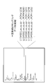
- FIG. 4 is a diagram showing an example of motor drive file information and voice data frame number.
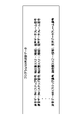
- FIG. 5 is a diagram showing sampling data included in the motor drive file information and voice data.
- FIG. 4 shows sampling data having a fixed period.
- the sampling data is "L13 # 001.xx.yy.zz ..., PCM # 1236", “L13 # 002.xx.yy.zz ..., PCM # 1240", "L13”. # 003.xx.yy.zz ..., PCM # 1244 ",” L13 # 004.xx.yy.zz ..., PCM # 1248 “,” L13 # 005.xx.yy.zz ..., PCM # 1252 "and the like.
- the position information may include position feedback information in addition to the position command
- the speed information may include speed feedback information in addition to the speed command.
- FIG. 5 as the X-axis position information, the X-axis position command and the sampling data of the position feedback information as shown in FIG. 5 are recorded, and the audio data frame number corresponding to the sampling data of the audio data shown in FIG. Shows an example of what was remembered.
- the machine tool 10 includes an arithmetic processing unit such as a CPU (Central Processing Unit). Further, the machine tool 10 is a temporary storage device such as an HDD (Hard Disk Drive) that stores various control programs such as application software or an OS (Operating System), and an arithmetic processing device for executing a program. It also has a main storage device such as a RAM (Random Access Memory) for storing the data required for the operating system.
- arithmetic processing unit such as a CPU (Central Processing Unit).
- the machine tool 10 is a temporary storage device such as an HDD (Hard Disk Drive) that stores various control programs such as application software or an OS (Operating System), and an arithmetic processing device for executing a program. It also has a main storage device such as a RAM (Random Access Memory) for storing the data required for the operating system.
- RAM Random Access Memory
- the arithmetic processing device reads the application software or the OS from the auxiliary storage device, and while deploying the read application software or the OS to the main storage device, performs arithmetic processing based on these application software or the OS. .. Further, based on the calculation result, various hardware included in each device is controlled. Thereby, the functional block of this embodiment is realized. That is, this embodiment can be realized by the cooperation of hardware and software.
- FIG. 6 is a flowchart showing the operation of the machine tool.
- step S11 it is determined whether the mode of the machine tool 10 is the muffling data recording mode or the muffling mode. If it is the storage mode, the process proceeds to the muffling data recording process of step S12, and if it is the muffling mode, Move to step S13.
- the muffling data recording process in step S12 will be described later.
- step S13 the muffling data reading unit 212 determines whether or not the muffling data storage unit 110 has muffling data, and if there is muffling data, the process proceeds to the muffling control process of step S14, and if there is no muffling data, the process proceeds to step S15. ..
- the muffling control process in step S14 will be described later.
- step S15 it is determined whether the processing is continued.
- the NC program When the NC program is executed without acquiring the muffling data, it warns the user that the sufficient muffling effect cannot be obtained, confirms whether to continue machining, and determines whether to continue machining based on the user's instructions. Is done. Confirmation as to whether or not to continue machining depends on, for example, a dialogue using a user interface such as a confirmation dialog or the presence or absence of machining parameter settings.
- the active muffling feedback control process in step S16 is performed, and when the processing is stopped, the process is terminated. The active muffling feedback control process in step S16 will be described later.
- FIG. 7 is a flowchart showing the muffling data recording process.
- step S121 the processed sound input unit 231 outputs the processed sound data input via the microphone 250 to the antiphase generation unit 232.
- step S122 the anti-phase generation unit 232 generates anti-phase voice data with respect to the processed sound data, and outputs the anti-phase voice data to the muffling data recording unit 211.
- step S123 the muffling data recording unit 211 is generated based on the voice data of the opposite phase to the processed sound data output from the antiphase generation unit 232 and the NC program output from the NC program control unit 222. At least one of the position command and the speed command to be performed is associated with and stored in the muffling data storage unit 110 as muffling data.
- the motor drive profile information and the voice data frame number for a certain NC program are stored in the sound deadening data recording unit 211 as the sound deadening data for the program 001 shown in FIG. 8, and the voice data file corresponding to the voice data frame number is also sound deadening data. It is stored in the recording unit 211.
- FIG. 8 shows an example in which the velocity information is not recorded and only the axis position information of the X-axis, the Y-axis, and the Z-axis is recorded.
- FIG. 9 is a flowchart showing the muffling control process.
- step S141 the NC program control unit 222 outputs at least one of the position command and the speed command acquired from the axis control unit 223 to the muffling data reading unit 212, and associates them with at least one of the position command and the speed command.
- the obtained anti-phase voice data is acquired from the mute data reading unit 212, and a mute control instruction including the anti-phase voice data is output to the mute PID control unit 233.
- step S142 the muffling PID control unit 233 receives a muffling control instruction including the voice data of the opposite phase, and outputs the voice data of the opposite phase to the muffling signal output unit 234.
- step S143 the mute signal output unit 234 outputs the voice data of the opposite phase to the speaker 240 to output the mute signal.
- step S144 it is determined whether or not the NC program has ended, and if it does not end, the process proceeds to step S145, and if it ends, the process ends.
- step S145 the processed sound input unit 231 outputs the voice data based on the canceled voice input via the microphone 250 to the antiphase generation unit 232.
- step S142 when the voice data having the opposite phase to the voice data of the offset voice is input as error data, the mute PID control unit 233 uses the error data to be used by the NC control unit. PID control is performed by adjusting the voice data of the opposite phase output from 220. After that, the operations of step S143 and step S144 are performed.
- FIG. 10 is a flowchart showing an active muffling feedback control process.
- step S161 the processed sound input unit 231 outputs the processed sound data input via the microphone 250 to the antiphase generation unit 232.
- step S162 the anti-phase generation unit 232 generates anti-phase voice data with respect to the processed sound data, and outputs the anti-phase voice data to the mute PID control unit 233.
- step S163 the muffling PID control unit 233 PID-controls the anti-phase processed sound data generated by the anti-phase generation unit 232 and outputs it to the muffling signal output unit 234.
- step S164 the muffling signal output unit 234 outputs the processed sound data of the opposite phase to the speaker 240 to output the muffling signal.
- step S165 it is determined whether or not the NC program has ended. If it does not end, the process returns to step S161, and if it ends, the process ends.
- FIG. 11 is a diagram showing a state in which the processed sound is canceled by the sound having the opposite phase and the sound is muted.
- the user may be able to set ON / OFF of the mute function, ON / OFF of the mute timer interlocking function, and mute time in the night operation mode on the setting screen of the operation unit provided in the numerical control device.
- the operation unit is composed of a liquid crystal display device with a touch panel and the like.
- FIG. 12 is a diagram showing a setting screen of an operation unit provided in the numerical control device.
- the generated sound can be canceled out as a feed forward in conjunction with at least one of the position information and the speed information, it is possible to obtain a high muffling effect with little delay.
- Each component included in the machine tool of each embodiment or the numerical control device can be realized by hardware, software, or a combination thereof. Further, a servo control method performed by cooperation of each component included in the above-mentioned machine tool or numerical control device can also be realized by hardware, software, or a combination thereof.
- what is realized by software means that it is realized by a computer reading and executing a program.
- Non-temporary computer-readable media include various types of tangible storage media.
- Examples of non-temporary computer-readable media include magnetic recording media (eg, hard disk drives), optomagnetic recording media (eg, optomagnetic disks), CD-ROMs (Read Only Memory), CD-Rs, CD-Rs /. W, a semiconductor memory (for example, mask ROM, PROM (Programmable ROM), EPROM (Erasable PROM), flash ROM, RAM (random access memory)).
- FIG. 13 is a block diagram showing another configuration example of the machine tool.
- the machine tool 10A shown in FIG. 13 differs from the machine tool 10 shown in FIG. 1 in that the speaker 240 and the microphone 250 are provided outside the machine tool 10A, and the muffling control unit 230 shown in FIG. 1 is a muffling control device.
- the 230A is provided outside the numerical control device 200A.
- the numerical control device 200A has the same configuration as the numerical control device 200 except that the muffling control unit 230 is not provided.
- the speaker and the microphone are provided to the outside, it is possible to mute the processing sound emitted from the machine tool to the outside. Further, since the muffling control device 230A is provided independently of the numerical control device 200A, the muffling control device 230A can be replaced separately from the numerical control device 200A.
- a second embodiment of the present disclosure is a numerical control system including a plurality of numerical control devices, a plurality of numerical control devices, and a muffling data server connected via a network.
- FIG. 14 is a block diagram showing a numerical control system according to a second embodiment of the present disclosure.
- the numerical control system 20 includes n (n is a natural number of 2 or more) numerical control devices 200-1 to 200-n and n numerical control devices 200-1 to 200-n. It includes a muffling data server 300 connected via the network 400.
- the numerical control devices 200-1 to 200-n have the same configuration as the numerical control device 200 shown in FIG. 1 or the numerical control device 200A shown in FIG.
- Numerical control devices 200-1 to 200-n are provided in the machine tool, respectively.
- the configuration of the machine tool is the same as that of the machine tool 10 shown in FIG. 1 or the machine tool 10A shown in FIG. 13 except that the muffling data storage unit 110 is not provided.
- the muffling data server 300 stores the muffling data of the n numerical control devices 200-1 to 200-n in the storage unit, and the muffling data reading unit 212 of the n numerical control devices 200-1 to 200-n. Mute data is transmitted in response to the request of.
- the muffling data server 300 may store in the storage unit the voice data having the opposite phase to the voice data of the offset voice input from the microphone 250 generated by the muffling control unit 230 as error data.
- the network 400 is, for example, a LAN (Local Area Network) constructed in a factory, the Internet, a public telephone network, or a combination thereof.
- the specific communication method in the network 400 and whether it is a wired connection or a wireless connection are not particularly limited.
- the muffling data measured by a specific numerical control device is shared by another numerical control device to mute the sound. Is possible.
- FIG. 15 is a block diagram showing another configuration example of the numerical control system.
- the numerical control system 20A of this configuration example is provided with a server 500 in place of the muffling data server 300 of the numerical control system 20 shown in FIG.
- the server 500 stores the muffling data of each of the n numerical control devices 200-1 to 200-n, and also stores the NC program to be input to the n numerical control devices 200-1 to 200-n.
- the server 500 can deliver the muffling data together with the NC program. In this embodiment, it is not necessary for each numerical control device to store the NC program.
- the numerical control device may be provided outside the machine tool.
- the storage device 100 shown in FIGS. 1 and 11 may be included in the numerical control device 200 or 200A.
- the NC program executed in the mute mode has been described as being the same as the NC program operating in the recording mode.
- some of the NC programs executed in the mute mode include the position information and speed in the second servo control in the mute mode, which are the same as the position information and speed information in the first servo control in the recording mode. If the servo control operation of the motor operated by information is included, the sound generated by the second servo control operation can be muted in the mute mode, so that the NC program executed in the mute mode is the NC program executed in the recording mode. It may be an NC program different from the above.
- the sound generated during machining differs depending on the NC program, but also depends on the type of tool or the material of the workpiece.
- Information on the type of tool or the material of the workpiece can be included in the muffling data as CAD data or CAM data (design information for creating an NC program) or parameter information instructed by the user. If the parameter information is different from the parameter information at the time of recording the mute data, a warning can be displayed and it can be confirmed whether or not the mute control process is performed.
- a numerical control device eg, numerical control device 200 or 200A
- a motor for example, motors 261, 262, 263
- a control unit for example, NC control unit 220
- the control unit performs the first servo control of the motor, the information including at least one of the position information and the speed information of the motor and the machine tool, the robot, or the industrial machine are operated.
- a muffling data management unit (for example, muffling data management unit 210) that associates and stores the sound data of the sound having the opposite phase with respect to the sound generated by the storage unit.
- the control unit performs a second servo control of the motor that operates with at least one of the same position information as the position information and the same speed information as the speed information, at least the second one.
- At least one of the position information and the speed information in the servo control is output to the muffling data management unit.
- the muffling data management unit reads out the voice data of the opposite phase sound from the storage unit based on at least one of the position information and the speed information in the second servo control, and outputs the voice data.
- the sound data of the anti-phase sound output from the muffling data management unit is a numerical control device used to cancel the sound generated by the machine tool, the robot, or the industrial machine. According to this numerical control device, since the generated sound can be canceled out as a feed forward in conjunction with at least one of the position information and the speed information, a high muffling effect with little delay can be obtained.
- a muffling control unit (for example, muffling) that outputs the sound data of the opposite phase sound output from the muffling data management unit in order to cancel the sound generated by the machine tool, the robot, or the industrial machine.
- the muffling control unit is from the muffling data management unit by feedback control using voice data of sounds having a phase opposite to the sound after canceling the sounds generated by the machine tool, the robot, or the industrial machine.
- the muffling control unit is the voice data of the sound of the opposite phase to the sound generated by the machine tool, the robot or the industrial machine.
- the numerical control device according to (3) or (4) above, which generates and outputs.
- a plurality of numerical control devices according to any one of (1) to (6) above, and It is equipped with a plurality of the numerical control devices and a server (300, 500) connected via a network.
- the server includes information including at least one of motor position information and speed information when at least one of the plurality of numerical control devices performs first servo control of the motor.
- a numerical control system having a storage unit that stores a voice data of a sound having a phase opposite to a sound generated by operating a machine tool, a robot, or an industrial machine in association with each other. According to this numerical control system, it is possible to cancel out the generated sound as feedforward in conjunction with at least one of the position information and the speed information, so that a high muffling effect with little delay can be obtained.
- the sound data of the sound having the opposite phase to the sound after canceling the sound generated by the machine tool, the robot, or the industrial machine is stored in the storage unit in association with the information. Numerical control system described.
- a method for muting a numerical control device for example, a numerical control device 200 or 200A
- a motor for example, motors 261, 262, 263
- Servo control the motor based on the numerical control program It is generated by operating the machine tool, the robot, or the industrial machine with information including at least one of the position information and the speed information of the motor when the first servo control of the motor is performed.
- the audio data of the sound of the opposite phase to the sound is linked and stored in the storage unit.
- the voice data of the sound of the opposite phase is read from the storage unit, and the voice data is read.
- Silent data storage unit 120 NC program storage unit 200, 200A Numerical control device 210 Silent data management unit 220 NC control unit 230 Silent control unit 240 Speaker 250 Microphone 261, 262, 263 Motor 300 Silent data server 400 Network 500 Server
Landscapes
- Engineering & Computer Science (AREA)
- Physics & Mathematics (AREA)
- Acoustics & Sound (AREA)
- Multimedia (AREA)
- Human Computer Interaction (AREA)
- Manufacturing & Machinery (AREA)
- General Physics & Mathematics (AREA)
- Automation & Control Theory (AREA)
- Soundproofing, Sound Blocking, And Sound Damping (AREA)
- Numerical Control (AREA)
Abstract
Description
工作機械から発生する騒音を抑制するために、騒音を検出して、騒音とは逆位相の音を発生させて消音する装置が、特許文献1及び特許文献2に記載されている。
特許文献2には、工作機械装置が、工作機械を運転する際に発生する、駆動音、冷却音、切削音、研削音等を第一の圧力検出器で検出し、この信号を基に逆位相信号を演算装置で算出し、工作機械に設けた消音スピーカから逆位相音波を発生し、各騒音の消音を行なうことが記載されている。
特許文献3には、情報処理装置と情報処理装置とは別体の周辺装置とがインターフェースされる情報システムにおいて、情報処理装置が、周辺装置を特定する機器特定部と、機器特定部により特定された周辺装置に対応して周辺装置の動作音を相殺する位相特性を有する動作音相殺データを取得するデータ取得部とを備えていることが記載されている。そして、特許文献3には、情報処理装置は動作音相殺部を備えており、データ取得部により取得された動作音相殺データを音声出力機能に出力して音声に重畳して出力することが記載されている。
よって、騒音発生又は停止から消音効果の追従まで遅延が少ない数値制御装置、数値制御システム及び消音方法が望まれる。
数値制御プログラムに基づいて前記モータをサーボ制御する制御部と、
前記制御部が前記モータの第1のサーボ制御を行う場合の、前記モータの位置情報、及び速度情報のうちの少なくとも一つを含む情報と、前記工作機械、前記ロボット又は前記産業機械を動作させることで発生する音に対する逆位相の音の音声データと、を紐づけて記憶部に記憶する消音データ管理部と、を備え、
前記制御部は、前記位置情報と同一の位置情報、及び前記速度情報と同一の速度情報のうちの少なくとも一つで動作する前記モータの第2のサーボ制御を行う場合に、少なくとも前記第2のサーボ制御における前記位置情報、及び前記速度情報のうちの少なくとも一つを前記消音データ管理部に出力し、
前記消音データ管理部は、前記第2のサーボ制御における前記位置情報、及び前記速度情報のうちの少なくとも一つに基づいて前記記憶部から前記逆位相の音の音声データを読み出して出力し、
前記消音データ管理部から出力された前記逆位相の音の音声データは、前記工作機械、前記ロボット又は前記産業機械で発生した音を相殺するために用いられる、数値制御装置である。
複数の前記数値制御装置とネットワークを介して接続されるサーバとを備え、
前記サーバは、複数の前記数値制御装置のうちの少なくとも1つの数値制御装置が、モータの第1のサーボ制御をするときの、モータの位置情報、及び速度情報のうちの少なくとも一つを含む情報と、工作機械、ロボット又は産業機械を動作させることで発生する音に対する逆位相の音の音声データと、を紐づけて記憶する記憶部を有する数値制御システムである。
数値制御プログラムに基づいて前記モータをサーボ制御し、
前記モータの第1のサーボ制御を行う場合の、前記モータの位置情報、及び速度情報のうちの少なくとも一つを含む情報と、前記工作機械、前記ロボット又は前記産業機械を動作させることで発生する音に対する逆位相の音の音声データと、を紐づけて記憶部に記憶し、
前記位置情報と同一の位置情報、及び前記速度情報と同一の速度情報のうちの少なくとも一つで動作する前記モータの第2のサーボ制御を行う場合に、少なくとも前記第2のサーボ制御における前記位置情報、及び前記速度情報のうちの少なくとも一つに基づいて前記記憶部から前記逆位相の音の音声データを読み出し、
読み出された前記逆位相の音の音声データを、前記工作機械、前記ロボット又は前記産業機械で発生した音を相殺するために用いる、消音方法である。
以下に説明する実施形態では、数値制御装置が工作機械を動作させるモータを制御する例について説明するが、数値制御装置はロボット又は産業機械を動作させるモータを制御する場合にも用いることができる。
図1は本開示の第1の実施形態の数値制御装置を含む工作機械を示すブロック図である。
図1に示すように、工作機械10は、記憶装置100、数値制御装置200、スピーカ240、マイク250、モータ261、モータ262及びモータ263を備えている。
記憶装置100は、消音データを記憶する消音データ記憶部110及びNCプログラム(数値制御プログラム)を記憶するNCプログラム記憶部120を備えている。消音データの詳細については後述する。
数値制御装置200は、消音データ管理部210、NC制御部220及び消音制御部230を備えている。消音データ管理部210、NC制御部220及び消音制御部230の構成及び動作の詳細については後述する。
記録モードでは、工作機械10は、騒音と逆位相の音の音声データを含む消音データの記録処理を行う。消音モードでは、工作機械10は、消音データ記憶部110に消音データが記録されていれば消音制御処理を行い、消音データ記憶部110に消音データが記録されていなければアクティブ消音フィードバック制御処理を行う。
騒音には、切削等の加工により発生する加工音の他、モータの回転音、冷却装置のファンによる音等が含まれる。以下、騒音が加工音である場合について説明する。
まず、工作機械10の記録モードについて説明する。記録モードにおいて、工作機械10は以下の消音データ記録処理を行う。
(消音データ記録処理)
NC制御部220は、NCプログラム記憶部120からNCプログラムを読み出し、読み出したNCプログラムに基づいて、モータ261~263をサーボ制御する。記録モードにおけるサーボ制御は第1のサーボ制御となる。モータ261~263の制御により機械加工が行われ、発生した加工音をマイク250で検出する。
消音制御部230は、マイク250から入力された加工音の音声データ(以下、加工音データという)に対して逆位相の音声データを生成して、消音データ管理部210に入力する。
NC制御部220は、NCプログラムに基づいて生成される位置指令及び速度指令の少なくとも1つを、消音データ管理部210に入力する。
消音データ管理部210は、逆位相の音声データと、位置指令及び速度指令の少なくとも1つとを紐づけ、消音データとして消音データ記憶部110に記憶する。逆位相の音声データに紐づけられて記憶される情報は、位置指令、及び速度指令の一方でも両方でもよい。
以上のように、NCプログラムにより発生する加工音を相殺するための逆位相の音声データが消音データ記憶部110に記憶される。
さらに、逆位相の音声データに紐づけられて記憶される情報として、NCプログラムのファイル名又はファイル管理番号が、消音データ記憶部110に記憶されてもよい。ファイル名又はファイル管理番号を、逆位相の音声データに紐づけて消音データ記憶部110に記憶することで、逆位相の音声データが、どのNCプログラムを実行する際のデータなのかを明確にすることができる。
次に、工作機械10の消音モードについて説明する。
NC制御部220が、NCプログラム記憶部120から、消音データ記録処理時に読み出したNCプログラムと同一のNCプログラムを読み出して、モータ261~263をサーボ制御する。消音モードにおけるサーボ制御は第2のサーボ制御となる。NC制御部220は、同一のNCプログラムに基づいて生成される、位置指令及び速度指令の少なくとも1つを消音データ管理部210に入力する。
消音データ管理部210に入力される情報は、消音データ記録処理において、逆位相の音声データに紐づけられて記憶された情報に含まれる情報とする。ユーザは、逆位相の音声データに紐づけられて記憶される情報を予め決め、消音データ管理部210に入力される情報も、逆位相の音声データに紐づけられて記憶される情報に基づいて決める。例えば、ユーザは、消音データ記憶部110に記憶される情報を、位置指令及び速度指令の両方としたときは、消音データ管理部210に入力される情報を、位置指令若しくは速度指令、又は位置指令及び速度指令とする。また、ユーザは、消音データ記憶部110に記憶される情報を、位置フィードバック情報及び速度フィードバック情報の両方としたときは、消音データ管理部210に入力される情報を、位置フィードバック情報若しくは速度フィードバック情報、又は位置フィードバック情報及び速度フィードバック情報とする。
逆位相の音声データと紐づけられて記憶された情報が、モータの位置及び速度の少なくとも1つを示す情報なので、消音データ管理部210に入力される情報も、モータの位置及び速度の少なくとも1つを示す情報となる。消音モードで実行されるNCプログラムは、記録モードで実行されるNCプログラムと同一であるため、消音モードで得られる位置情報及び速度情報は、記録モードで得られる位置情報及び速度情報と同一の情報となる。
なお、NC制御部220は、逆位相の音声データに紐づけてプログラムステップ情報が、消音データ記憶部110に記憶されている場合は、プログラムステップ情報を入力してもよい。また、逆位相の音声データに紐づけてファイル名又はファイル管理番号が、消音データ記憶部110に記憶されている場合は、ファイル名又はファイル管理番号を入力してもよい。
以下の説明では、逆位相の音声データと紐づけられて記憶された情報が、位置指令及び速度指令の少なくとも1つであり、消音データ管理部210に入力される情報も、位置指令及び速度指令の少なくとも1つであるとする。
消音データ管理部210は、消音データが消音データ記憶部110にあれば、以下の消音制御処理を行い、消音データが消音データ記憶部110になければ、以下のアクティブ消音フィードバック制御処理を行う。
消音データ管理部210は、消音データ記憶部110から、消音データに含まれる逆位相の音声データを読み出してNC制御部220に出力する。
NC制御部220は、消音制御部230に逆位相の音声データを含む消音制御指示を出力する。
消音制御部230は、NC制御部220から出力された、逆位相の音声データに基づいてスピーカ240から逆位相の音声を出力し、発生した加工音を相殺する。
消音制御部230は、マイク250から入力された相殺後の音声の音声データに対して逆位相の音声データを誤差データとして生成して、この誤差データを用いて、NC制御部220から出力される逆位相の音声データを調整し、PID制御(Proportional Integral Differential Control)を行い、スピーカ240から逆位相の音声を出力してもよい。
消音データ管理部210は、NC制御部220に逆位相の音声データ記憶なしの通知を出力する。NC制御部220は、逆位相の音声データ記憶なしの通知を受けると、消音制御部230にアクティブ消音フィードバック制御の指示を出力する。消音制御部230は、アクティブ消音フィードバック制御の指示を受けると、マイク250から入力された加工音の加工音データに対して逆位相の音声データを生成して、PID制御を行い、スピーカ240から逆位相の音声を出力し、発生した加工音を相殺する。
以下、数値制御装置200の消音データ管理部210、NC制御部220及び消音制御部230の構成及び動作について説明する。
消音データ読み出し部212は、上述した消音制御処理において、位置指令及び速度指令の少なくとも1つを含む読み出し指示をNC制御部220から受け、位置指令及び速度指令の少なくとも1つに基づいて消音データ記憶部110から逆位相の音声データを読み出してNC制御部220に出力する。消音データ読み出し部212は、NC制御部220から出力された、位置指令及び速度指令の少なくとも1つに対応する逆位相の音声データが消音データ記憶部110に記憶されていない場合は、NC制御部220に逆位相の音声データの記憶なしの通知を出力する。
また、NCプログラム制御部222は、上述した消音データ記録処理において、軸制御部223から取得した、位置指令及び速度指令の少なくとも1つを消音データ記録部211に出力する。
また、NCプログラム制御部222は、上述した消音制御処理において、軸制御部223から取得した、位置指令及び速度指令の少なくとも1つを消音データ読み出し部212に出力し、位置指令及び速度指令の少なくとも1つに紐づけられた逆位相の音声データを消音データ読み出し部212から取得する。そして、NCプログラム制御部222は、消音PID制御部233に逆位相の音声データを含む消音制御指示を出力する。
更に、NCプログラム制御部222は、上述したアクティブ消音フィードバック制御処理において、消音データ読み出し部212から、逆位相の音声データの記憶なしの通知を受けると、消音PID制御部233にアクティブ消音フィードバック制御の指示を出力する。
例えば、工作機械が3軸加工機で、軸制御部223が、被加工物(ワーク)を搭載するテーブルをX軸方向及びY軸方向に移動させ、工具が取り付けられた主軸をZ方向に移動させて、被加工物を加工する場合には、X軸方向、Y軸方向及びZ方向に対してそれぞれ軸制御部223が設けられる。
位置制御部2232は、位置偏差にポジションゲインKpを乗じた値を、速度指令として減算器2233に出力する。
減算器2233は、速度指令及び速度フィードバックされた速度検出値との差を求め、その差を速度偏差として速度制御部2234に出力する。
速度制御部2234は、速度偏差に積分ゲインK1vを乗じて積分した値と、速度偏差に比例ゲインK2vを乗じた値とを加算して、トルク指令値としてモータ261に出力してモータ261を駆動する。
モータ261の回転角度位置は、モータ261に関連付けられた、位置検出部となるロータリーエンコーダによって検出され、速度検出値は速度フィードバック情報として減算器2233に入力される。速度検出値は積分器2235で積分されて位置検出値となり、位置検出値は位置フィードバック情報として減算器2231に入力される。
逆位相生成部232は、上述した消音データ記録処理の場合には、逆位相の音声データを消音データ記録部211に出力する。
逆位相生成部232は、上述した消音制御処理の場合には、加工音が逆位相の音声により相殺された後の音声の音声データに対して逆位相の音声データを消音PID制御部233に出力する。
逆位相生成部232は、上述したアクティブ消音フィードバック制御処理の場合には、逆位相の音声データを消音PID制御部233に出力する。
消音PID制御部233は、逆位相生成部232から、相殺後の音声の音声データに対して逆位相の音声データが誤差データとして入力された場合、この誤差データを用いて、NC制御部220から出力される逆位相の音声データを調整し、PID制御を行い、消音信号出力部234に出力してもよい。
消音PID制御部233は、上述したアクティブ消音フィードバック制御処理の場合に、アクティブ消音フィードバック制御の指示を受けると、逆位相生成部232から逆位相の音声データを取得して、PID制御を行い、消音信号出力部234に出力する。
消音データ記録部211が消音データ記憶部110に記憶する消音データは、図3に示す構成を有する。図3は消音データの構成を示す図である。
消音データ記録部211は、NCプログラムに連動したNCプログラムファイル情報(各軸の位置情報、速度情報等)のログデータにあわせて、逆位相生成部232から取得したアナログ音声データを変換したデジタル音声データのサンプリングフレーム番号を記録する。
消音データは、図3に示すように、ヘッダ部、レコード部及び音声データを備えている。
モータ駆動プロファイル情報は、プログラムステップ情報及び各軸の各軸の位置情報、速度情報を含んでいる。
プログラムステップ情報は、NCプログラムのプログラム行番号、又はNCプログラムに対するプログラム解析により、指令の単位に展開された内部のステップ番号を示す。
各軸の各軸の位置情報、速度情報は、図3では例えば、X軸の位置情報としてX軸の位置指令、X軸の速度情報としてX軸の速度指令が記憶される。各軸の位置情報には、各軸の位置指令の他に位置フィードバック情報を含めてもよく、各軸の速度情報には、各軸の速度指令の他に速度フィードバック情報を含めてもよい。
音声データフレーム番号は、音声データの音声データファイル内の時間情報またはサンプリング番号などの音声データ再生位置を特定するための情報を示す番号である。
図4では、一定周期のサンプリングデータを示している。サンプリングデータは、図4に示すように「L13#001.xx.yy.zz・・・,PCM#1236」、「L13#002.xx.yy.zz・・・,PCM#1240」、「L13#003.xx.yy.zz・・・,PCM#1244」、「L13#004.xx.yy.zz・・・,PCM#1248」、「L13#005.xx.yy.zz・・・,PCM#1252」等である。これらのサンプリングデータにおいて、例えば「L13#001」はプログラムステップ情報を示し、「xx」はX軸位置情報とX軸速度情報を示し、「yy」はY軸位置情報とY軸速度情報を示し、「zz」はZ軸位置情報とZ軸速度情報を示し、「PCM#1236」は音声データフレーム番号を示す。
例えば、位置情報には、位置指令の他に位置フィードバック情報を含め、速度情報には、速度指令の他に速度フィードバック情報を含めてもよい。図5では、X軸位置情報としては、X軸の位置指令と、図5に示すような位置フィードバック情報のサンプリングデータが記録され、図5に示す音声データのサンプリングデータに対応する音声データフレーム番号が記憶された例を示している。
これらの機能ブロックを実現するために、工作機械10は、CPU(Central Processing Unit)等の演算処理装置を備える。また、工作機械10は、アプリケーションソフトウェア又はOS(Operating System)等の各種の制御用プログラムを格納したHDD(Hard Disk Drive)等の補助記憶装置や、演算処理装置がプログラムを実行する上で一時的に必要とされるデータを格納するためのRAM(Random Access Memory)といった主記憶装置も備える。
図7は消音データ記録処理を示すフローチャートである。
図9は消音制御処理を示すフローチャートである。
ステップS145の後のステップS142において、消音PID制御部233は、相殺後の音声の音声データに対して逆位相の音声データが誤差データとして入力された場合、この誤差データを用いて、NC制御部220から出力される逆位相の音声データを調整し、PID制御を行う。その後、ステップS143、ステップS144の動作を行う。
図10はアクティブ消音フィードバック制御処理を示すフローチャートである。
ステップS165において、NCプログラムが終了したかを判断し、終了しない場合はステップS161に戻り、終了する場合には処理を終了する。
さらに、フィードバック制御を併せて実行することで誤差に対する補正も行って消音効果を高めることもできる。
図11は加工音を逆位相の音声で相殺して消音する様子を示す図である。
<スピーカ及びマイクが外部に設けられ、消音制御部が数値制御装置の外部に設けられた変形例>
図13は工作機械の他の構成例を示すブロック図である。図13に示す工作機械10Aが、図1に示した工作機械10と異なる点は、スピーカ240及びマイク250が工作機械10Aの外部に設けられ、図1に示した消音制御部230が消音制御装置230Aとして数値制御装置200Aの外部に設けられていることである。数値制御装置200Aは、消音制御部230がない点を除いて数値制御装置200の構成と同じである。
本構成例の工作機械では、スピーカ及びマイクが外部に設けられるため、工作機械から外部に放出される加工音を消音することができる。また、消音制御装置230Aが数値制御装置200Aと独立して設けられるため、消音制御装置230Aを数値制御装置200Aとは別に交換可能となる。
本開示の第2の実施形態は、複数の数値制御装置と、複数の数値制御装置とネットワークを介して接続される消音データサーバとを備えた数値制御システムである。
図14は本開示の第2の実施形態の数値制御システムを示すブロック図である。図14に示すように、数値制御システム20は、n(nは2以上の自然数)台の数値制御装置200-1~200-nと、n台の数値制御装置200-1~200-nとネットワーク400を介して接続される消音データサーバ300とを備えている。
数値制御装置200-1~200-nは図1に示した数値制御装置200又は図13に示した数値制御装置200Aと同じ構成を有している。数値制御装置200-1~200-nはそれぞれ工作機械内に設けられている。工作機械の構成は図1に示した工作機械10又は図13に示した工作機械10Aと比べて消音データ記憶部110がない点を除いて同じである。
消音データサーバ300は、n台の数値制御装置200-1~200-nの各消音データを記憶部に記憶し、n台の数値制御装置200-1~200-nの各消音データ読み出し部212の要求に応じて消音データを送信する。
消音データサーバ300は、消音制御部230が生成した、マイク250から入力された相殺後の音声の音声データに対して逆位相の音声データを誤差データとして記憶部に記憶してもよい。
本実施形態において、同一の加工プログラムを複数の工作機械で共有して同時生産するような場合に、特定の数値制御装置が測定した消音データを他の数値制御装置が共有して消音を行うことが可能である。
<消音データ及びNCプログラムをサーバが送信する数値制御システムの変形例>
図15は数値制御システムの他の構成例を示すブロック図である。
本構成例の数値制御システム20Aは、図14に示した数値制御システム20の消音データサーバ300に替えてサーバ500を設けている。
サーバ500は、n台の数値制御装置200-1~200-nの各消音データを記憶するとともに、n台の数値制御装置200-1~200-nに入力するNCプログラムを記憶している。
本実施形態では、ある数値制御装置で行った試作加工の結果に問題なければ、サーバ500がNCプログラムと併せて消音データを配信することができる。
本実施形態では、NCプログラムを各数値制御装置が記憶しておく必要がなくなる。
例えば、第1及び第2の実施形態において、数値制御装置は、工作機械の外部に設けられてもよい。
また、図1及び図11に示した記憶装置100は、数値制御装置200又は200A内に含めてもよい。
上述した第1及び第2の実施形態においては、消音モードで実行されるNCプログラムは、記録モードで動作するNCプログラムと同一であるとして説明した。しかし、消音モードで実行されるNCプログラムの一部に、記録モードにおける第1のサーボ制御での位置情報及び速度情報とそれぞれ同一である、消音モードにおける第2のサーボ制御での位置情報及び速度情報で動作するモータのサーボ制御動作を含んでいれば、第2のサーボ制御動作により発生する音を消音モードで消音できるので、消音モードで実行されるNCプログラムは記録モードで実行されるNCプログラムと異なるNCプログラムであってもよい。
(1) 工作機械、ロボット又は産業機械を動作させるモータ(例えば、モータ261、262、263)を制御する数値制御装置(例えば、数値制御装置200又は200A)であって、
数値制御プログラムに基づいて前記モータをサーボ制御する制御部(例えば、NC制御部220)と、
前記制御部が前記モータの第1のサーボ制御を行う場合の、前記モータの位置情報、及び速度情報のうちの少なくとも一つを含む情報と、前記工作機械、前記ロボット又は前記産業機械を動作させることで発生する音に対する逆位相の音の音声データと、を紐づけて記憶部に記憶する消音データ管理部(例えば、消音データ管理部210)と、を備え、
前記制御部は、前記位置情報と同一の位置情報、及び前記速度情報と同一の速度情報のうちの少なくとも一つで動作する前記モータの第2のサーボ制御を行う場合に、少なくとも前記第2のサーボ制御における前記位置情報、及び前記速度情報のうちの少なくとも一つを前記消音データ管理部に出力し、
前記消音データ管理部は、前記第2のサーボ制御における前記位置情報、及び前記速度情報のうちの少なくとも一つに基づいて前記記憶部から前記逆位相の音の音声データを読み出して出力し、
前記消音データ管理部から出力された前記逆位相の音の音声データは、前記工作機械、前記ロボット又は前記産業機械で発生した音を相殺するために用いられる、数値制御装置。
この数値制御装置によれば、位置情報及び速度情報の少なくとも1つに連動してフィードフォワードとして発生音の相殺ができるため遅延の少ない高い消音効果を得ることができる。
複数の前記数値制御装置とネットワークを介して接続されるサーバ(300、500)とを備え、
前記サーバは、複数の前記数値制御装置のうちの少なくとも1つの数値制御装置が、モータの第1のサーボ制御をするときの、モータの位置情報、及び速度情報のうちの少なくとも一つを含む情報と、工作機械、ロボット又は産業機械を動作させることで発生する音に対する逆位相の音の音声データと、を紐づけて記憶する記憶部を有する数値制御システム。
この数値制御システムによれば、位置情報及び速度情報の少なくとも1つに連動してフィードフォワードとして発生音の相殺ができるため遅延の少ない高い消音効果を得ることができる。
数値制御プログラムに基づいて前記モータをサーボ制御し、
前記モータの第1のサーボ制御を行う場合の、前記モータの位置情報、及び速度情報のうちの少なくとも一つを含む情報と、前記工作機械、前記ロボット又は前記産業機械を動作させることで発生する音に対する逆位相の音の音声データと、を紐づけて記憶部に記憶し、
前記位置情報と同一の位置情報、及び前記速度情報と同一の速度情報のうちの少なくとも一つで動作する前記モータの第2のサーボ制御を行う場合に、少なくとも前記第2のサーボ制御における前記位置情報、及び前記速度情報のうちの少なくとも一つに基づいて前記記憶部から前記逆位相の音の音声データを読み出し、
読み出された前記逆位相の音の音声データを、前記工作機械、前記ロボット又は前記産業機械で発生した音を相殺するために用いる、消音方法。
この消音方法によれば、位置情報及び速度情報の少なくとも1つに連動してフィードフォワードとして発生音の相殺ができるため遅延の少ない高い消音効果を得ることができる。
110 消音データ記憶部
120 NCプログラム記憶部
200、200A 数値制御装置
210 消音データ管理部
220 NC制御部
230 消音制御部
240 スピーカ
250 マイク
261、262、263 モータ
300 消音データサーバ
400 ネットワーク
500 サーバ
Claims (10)
- 工作機械、ロボット又は産業機械を動作させるモータを制御する数値制御装置であって、
数値制御プログラムに基づいて前記モータをサーボ制御する制御部と、
前記制御部が前記モータの第1のサーボ制御を行う場合の、前記モータの位置情報、及び速度情報のうちの少なくとも一つを含む情報と、前記工作機械、前記ロボット又は前記産業機械を動作させることで発生する音に対する逆位相の音の音声データと、を紐づけて記憶部に記憶する消音データ管理部と、を備え、
前記制御部は、前記位置情報と同一の位置情報、及び前記速度情報と同一の速度情報のうちの少なくとも一つで動作する前記モータの第2のサーボ制御を行う場合に、少なくとも前記第2のサーボ制御における前記位置情報、及び前記速度情報のうちの少なくとも一つを前記消音データ管理部に出力し、
前記消音データ管理部は、前記第2のサーボ制御における前記位置情報、及び前記速度情報のうちの少なくとも一つに基づいて前記記憶部から前記逆位相の音の音声データを読み出して出力し、
前記消音データ管理部から出力された前記逆位相の音の音声データは、前記工作機械、前記ロボット又は前記産業機械で発生した音を相殺するために用いられる、数値制御装置。 - 前記消音データ管理部は、前記数値制御プログラムのプログラム行番号、又は前記数値制御プログラムに対するプログラム解析により、指令の単位に展開された内部のステップ番号を前記記憶部に記憶する、請求項1に記載の数値制御装置。
- 前記消音データ管理部から出力された前記逆位相の音の音声データを、前記工作機械、前記ロボット又は前記産業機械で発生した音を相殺するために出力する消音制御部を備えた請求項1又は2に記載の数値制御装置。
- 前記消音制御部は、前記工作機械、前記ロボット又は前記産業機械で発生した音を相殺した後の音に対する逆位相の音の音声データを用いたフィードバック制御により、前記消音データ管理部から出力される、逆位相の音の音声データを調整する、請求項3に記載の数値制御装置。
- 前記記憶部に逆位相の音の音声データが記憶されていない場合に、前記消音制御部は、前記工作機械、前記ロボット又は前記産業機械で発生した音に対する逆位相の音の音声データを生成して出力する、請求項3又は4に記載の数値制御装置。
- 前記第1及び第2のサーボ制御における、前記位置情報は位置指令であり、前記速度情報は速度指令である、請求項1から5のいずれか1項に記載の数値制御装置。
- 複数の、請求項1から請求項6のいずれか1項に記載の数値制御装置と、
複数の前記数値制御装置とネットワークを介して接続されるサーバとを備え、
前記サーバは、複数の前記数値制御装置のうちの少なくとも1つの数値制御装置が、モータの第1のサーボ制御をするときの、モータの位置情報、及び速度情報のうちの少なくとも一つを含む情報と、工作機械、ロボット又は産業機械を動作させることで発生する音に対する逆位相の音の音声データと、を紐づけて記憶する記憶部を有する数値制御システム。 - 前記記憶部に、前記工作機械、前記ロボット又は前記産業機械で発生した音を相殺した後の音に対する逆位相の音の音声データを前記情報と紐づけて記憶する請求項7に記載の数値制御システム。
- 前記サーバは、前記工作機械、前記ロボット又は前記産業機械を動作させるモータを動作させるための数値制御プログラムを記憶する請求項7又は8に記載の数値制御システム。
- 工作機械、ロボット又は産業機械を動作させるモータを制御する数値制御装置の消音方法であって、
数値制御プログラムに基づいて前記モータをサーボ制御し、
前記モータの第1のサーボ制御を行う場合の、前記モータの位置情報、及び速度情報のうちの少なくとも一つを含む情報と、前記工作機械、前記ロボット又は前記産業機械を動作させることで発生する音に対する逆位相の音の音声データと、を紐づけて記憶部に記憶し、
前記位置情報と同一の位置情報、及び前記速度情報と同一の速度情報のうちの少なくとも一つで動作する前記モータの第2のサーボ制御を行う場合に、少なくとも前記第2のサーボ制御における前記位置情報、及び前記速度情報のうちの少なくとも一つに基づいて前記記憶部から前記逆位相の音の音声データを読み出し、
読み出された前記逆位相の音の音声データを、前記工作機械、前記ロボット又は前記産業機械で発生した音を相殺するために用いる、消音方法。
Priority Applications (4)
| Application Number | Priority Date | Filing Date | Title |
|---|---|---|---|
| JP2022572199A JPWO2022138338A1 (ja) | 2020-12-21 | 2021-12-14 | |
| DE112021005206.3T DE112021005206T5 (de) | 2020-12-21 | 2021-12-14 | Numerische Steuervorrichtung, Numerisches Steuersystem und ein Verfahren zur Rauschreduzierung |
| CN202180083780.9A CN116569253A (zh) | 2020-12-21 | 2021-12-14 | 数值控制装置、数值控制系统以及降噪方法 |
| US18/039,375 US20240036551A1 (en) | 2020-12-21 | 2021-12-14 | Numerical control device, numerical control system, and silencing method |
Applications Claiming Priority (2)
| Application Number | Priority Date | Filing Date | Title |
|---|---|---|---|
| JP2020211455 | 2020-12-21 | ||
| JP2020-211455 | 2020-12-21 |
Publications (1)
| Publication Number | Publication Date |
|---|---|
| WO2022138338A1 true WO2022138338A1 (ja) | 2022-06-30 |
Family
ID=82159087
Family Applications (1)
| Application Number | Title | Priority Date | Filing Date |
|---|---|---|---|
| PCT/JP2021/046109 Ceased WO2022138338A1 (ja) | 2020-12-21 | 2021-12-14 | 数値制御装置、数値制御システム及び消音方法 |
Country Status (5)
| Country | Link |
|---|---|
| US (1) | US20240036551A1 (ja) |
| JP (1) | JPWO2022138338A1 (ja) |
| CN (1) | CN116569253A (ja) |
| DE (1) | DE112021005206T5 (ja) |
| WO (1) | WO2022138338A1 (ja) |
Citations (3)
| Publication number | Priority date | Publication date | Assignee | Title |
|---|---|---|---|---|
| JPH05172658A (ja) * | 1991-12-24 | 1993-07-09 | Gijutsu Kenkyu Kumiai Iryo Fukushi Kiki Kenkyusho | レーザー照射装置 |
| JP2002079501A (ja) * | 2000-09-05 | 2002-03-19 | Heiwa Corp | ルータ加工装置及びルータ加工装置群の騒音制御システム |
| JP2018063394A (ja) * | 2016-10-14 | 2018-04-19 | トヨタ自動車株式会社 | 騒音低減システム |
Family Cites Families (9)
| Publication number | Priority date | Publication date | Assignee | Title |
|---|---|---|---|---|
| JPH06270033A (ja) | 1993-03-24 | 1994-09-27 | Matsushita Electric Ind Co Ltd | 工作機械装置 |
| JPH07281673A (ja) | 1994-04-07 | 1995-10-27 | Amada Metrecs Co Ltd | Nc工作機械のための能動消音方法およびその装置 |
| JP4552353B2 (ja) * | 2001-05-11 | 2010-09-29 | ソニー株式会社 | サーボ・アクチュエータ並びにその位置検出装置 |
| JP2011227219A (ja) | 2010-04-19 | 2011-11-10 | Buffalo Inc | 情報システム、動作音を相殺するためのプログラム、および動作音相殺方法 |
| JP6638370B2 (ja) * | 2015-12-15 | 2020-01-29 | オムロン株式会社 | 制御装置、監視システム、制御プログラムおよび記録媒体 |
| KR102375215B1 (ko) * | 2016-03-07 | 2022-03-16 | 쓰리엠 이노베이티브 프로퍼티즈 캄파니 | 개인 보호 장비에 대한 지능형 안전 모니터링 및 분석 시스템 |
| JP7220353B2 (ja) * | 2017-08-08 | 2023-02-10 | パナソニックIpマネジメント株式会社 | コントローラの情報送信方法及びエンコーダの異常検出方法 |
| JP7444566B2 (ja) * | 2019-09-12 | 2024-03-06 | ファナック株式会社 | サーボ制御装置、サーボ制御システム及びサーボ制御方法 |
| US11940772B2 (en) * | 2020-09-11 | 2024-03-26 | Mitsubishi Electric Corporation | Numerical controller and industrial machine control system |
-
2021
- 2021-12-14 US US18/039,375 patent/US20240036551A1/en active Pending
- 2021-12-14 JP JP2022572199A patent/JPWO2022138338A1/ja active Pending
- 2021-12-14 CN CN202180083780.9A patent/CN116569253A/zh not_active Withdrawn
- 2021-12-14 WO PCT/JP2021/046109 patent/WO2022138338A1/ja not_active Ceased
- 2021-12-14 DE DE112021005206.3T patent/DE112021005206T5/de not_active Withdrawn
Patent Citations (3)
| Publication number | Priority date | Publication date | Assignee | Title |
|---|---|---|---|---|
| JPH05172658A (ja) * | 1991-12-24 | 1993-07-09 | Gijutsu Kenkyu Kumiai Iryo Fukushi Kiki Kenkyusho | レーザー照射装置 |
| JP2002079501A (ja) * | 2000-09-05 | 2002-03-19 | Heiwa Corp | ルータ加工装置及びルータ加工装置群の騒音制御システム |
| JP2018063394A (ja) * | 2016-10-14 | 2018-04-19 | トヨタ自動車株式会社 | 騒音低減システム |
Also Published As
| Publication number | Publication date |
|---|---|
| US20240036551A1 (en) | 2024-02-01 |
| DE112021005206T5 (de) | 2023-08-10 |
| JPWO2022138338A1 (ja) | 2022-06-30 |
| CN116569253A (zh) | 2023-08-08 |
Similar Documents
| Publication | Publication Date | Title |
|---|---|---|
| CN1173653A (zh) | 在机械系统中用于自适应抑制振动的设备和方法 | |
| JP2010520077A (ja) | フライス加工不具合を低減する方法および装置 | |
| CN103769945B (zh) | 颤振抑制方法和机床 | |
| JP2017182336A (ja) | 揺動切削を行う工作機械のサーボ制御装置、制御方法及びコンピュータプログラム | |
| CN102195545B (zh) | 电动机的控制装置 | |
| JP6806746B2 (ja) | モータ制御装置 | |
| JP7000371B2 (ja) | 機械学習装置、制御システム及び機械学習方法 | |
| JP6490368B2 (ja) | 工作機械制御装置、工作機械制御方法、及びプログラム | |
| JP6412071B2 (ja) | モータ制御装置、モータ制御方法及びモータ制御用プログラム | |
| WO2022138338A1 (ja) | 数値制御装置、数値制御システム及び消音方法 | |
| JP5886717B2 (ja) | 繰返し学習位置制御装置 | |
| JP6756601B2 (ja) | C軸機能を有する工作機械の制御装置及び制御方法 | |
| JP5848962B2 (ja) | 位置制御装置 | |
| JP7280310B2 (ja) | 数値制御装置 | |
| JP3466926B2 (ja) | サーボトラック書き込み方法とサーボトラック書き込み装置 | |
| JP2015100879A (ja) | 工作機械制御装置、工作機械制御方法、及びプログラム | |
| JP7433572B1 (ja) | 数値制御装置および数値制御方法 | |
| CN116710223B (zh) | 控制装置以及计算装置 | |
| Seki et al. | High-precision positioning considering suppression of resonant vibration modes by strain feedback | |
| JPH06270033A (ja) | 工作機械装置 | |
| JP2003084839A (ja) | オーバーシュート抑制機能を備えたモータ制御装置 | |
| WO2020230234A1 (ja) | 制御システムおよびモータ制御装置 | |
| JP2002335686A (ja) | モータ制御装置 | |
| WO2024042617A1 (ja) | 制御装置及びコンピュータ読み取り可能な記録媒体 | |
| JP2018063394A (ja) | 騒音低減システム |
Legal Events
| Date | Code | Title | Description |
|---|---|---|---|
| 121 | Ep: the epo has been informed by wipo that ep was designated in this application |
Ref document number: 21910487 Country of ref document: EP Kind code of ref document: A1 |
|
| WWE | Wipo information: entry into national phase |
Ref document number: 18039375 Country of ref document: US |
|
| WWE | Wipo information: entry into national phase |
Ref document number: 202180083780.9 Country of ref document: CN |
|
| ENP | Entry into the national phase |
Ref document number: 2022572199 Country of ref document: JP Kind code of ref document: A |
|
| 122 | Ep: pct application non-entry in european phase |
Ref document number: 21910487 Country of ref document: EP Kind code of ref document: A1 |