WO2022137933A1 - Article en céramique, procédé de moulage de matériau céramique, procédé de fabrication d'article en céramique et moule - Google Patents
Article en céramique, procédé de moulage de matériau céramique, procédé de fabrication d'article en céramique et moule Download PDFInfo
- Publication number
- WO2022137933A1 WO2022137933A1 PCT/JP2021/042664 JP2021042664W WO2022137933A1 WO 2022137933 A1 WO2022137933 A1 WO 2022137933A1 JP 2021042664 W JP2021042664 W JP 2021042664W WO 2022137933 A1 WO2022137933 A1 WO 2022137933A1
- Authority
- WO
- WIPO (PCT)
- Prior art keywords
- ceramic
- cavity
- molding
- molding die
- resin
- Prior art date
Links
- 239000000919 ceramic Substances 0.000 title claims abstract description 201
- 238000000465 moulding Methods 0.000 title claims abstract description 197
- 238000000034 method Methods 0.000 title claims abstract description 64
- 229910010293 ceramic material Inorganic materials 0.000 title claims abstract description 55
- 238000004519 manufacturing process Methods 0.000 title claims description 21
- 239000007788 liquid Substances 0.000 claims abstract description 81
- 238000005266 casting Methods 0.000 claims abstract description 80
- 229920005989 resin Polymers 0.000 claims abstract description 77
- 239000011347 resin Substances 0.000 claims abstract description 77
- 239000003125 aqueous solvent Substances 0.000 claims abstract description 48
- 238000005245 sintering Methods 0.000 claims abstract description 27
- 239000000843 powder Substances 0.000 claims abstract description 26
- 239000003795 chemical substances by application Substances 0.000 claims abstract description 23
- 239000002904 solvent Substances 0.000 claims abstract description 23
- 238000002156 mixing Methods 0.000 claims abstract description 18
- 238000001723 curing Methods 0.000 claims description 72
- 238000002347 injection Methods 0.000 claims description 37
- 239000007924 injection Substances 0.000 claims description 37
- 238000010304 firing Methods 0.000 claims description 26
- 239000003822 epoxy resin Substances 0.000 claims description 22
- 229920000647 polyepoxide Polymers 0.000 claims description 22
- 238000001035 drying Methods 0.000 claims description 19
- YMWUJEATGCHHMB-UHFFFAOYSA-N Dichloromethane Chemical compound ClCCl YMWUJEATGCHHMB-UHFFFAOYSA-N 0.000 claims description 18
- 239000004793 Polystyrene Substances 0.000 claims description 18
- 229920002223 polystyrene Polymers 0.000 claims description 18
- 238000005238 degreasing Methods 0.000 claims description 15
- 239000000463 material Substances 0.000 claims description 14
- 238000010438 heat treatment Methods 0.000 claims description 10
- XLYOFNOQVPJJNP-UHFFFAOYSA-N water Substances O XLYOFNOQVPJJNP-UHFFFAOYSA-N 0.000 claims description 10
- CSCPPACGZOOCGX-UHFFFAOYSA-N Acetone Chemical compound CC(C)=O CSCPPACGZOOCGX-UHFFFAOYSA-N 0.000 claims description 9
- YXFVVABEGXRONW-UHFFFAOYSA-N Toluene Chemical compound CC1=CC=CC=C1 YXFVVABEGXRONW-UHFFFAOYSA-N 0.000 claims description 9
- -1 sintering aid Substances 0.000 claims description 8
- 238000011049 filling Methods 0.000 claims description 7
- XMGQYMWWDOXHJM-JTQLQIEISA-N (+)-α-limonene Chemical compound CC(=C)[C@@H]1CCC(C)=CC1 XMGQYMWWDOXHJM-JTQLQIEISA-N 0.000 claims description 6
- 239000004925 Acrylic resin Substances 0.000 claims description 5
- 229920000178 Acrylic resin Polymers 0.000 claims description 4
- 229920000515 polycarbonate Polymers 0.000 claims description 4
- 239000004417 polycarbonate Substances 0.000 claims description 4
- 229920000728 polyester Polymers 0.000 claims description 4
- 239000000047 product Substances 0.000 description 89
- 239000002002 slurry Substances 0.000 description 45
- 230000002093 peripheral effect Effects 0.000 description 41
- 229910052581 Si3N4 Inorganic materials 0.000 description 28
- HQVNEWCFYHHQES-UHFFFAOYSA-N silicon nitride Chemical compound N12[Si]34N5[Si]62N3[Si]51N64 HQVNEWCFYHHQES-UHFFFAOYSA-N 0.000 description 28
- 238000002844 melting Methods 0.000 description 14
- 230000008018 melting Effects 0.000 description 14
- 238000005498 polishing Methods 0.000 description 13
- 239000002994 raw material Substances 0.000 description 13
- 238000002591 computed tomography Methods 0.000 description 10
- 239000002270 dispersing agent Substances 0.000 description 7
- 238000004090 dissolution Methods 0.000 description 7
- 229920000642 polymer Polymers 0.000 description 7
- 230000007547 defect Effects 0.000 description 6
- 238000011156 evaluation Methods 0.000 description 6
- 239000002245 particle Substances 0.000 description 6
- 238000007517 polishing process Methods 0.000 description 6
- 239000000203 mixture Substances 0.000 description 5
- 229910052799 carbon Inorganic materials 0.000 description 4
- 238000010586 diagram Methods 0.000 description 4
- 239000007789 gas Substances 0.000 description 4
- 239000003002 pH adjusting agent Substances 0.000 description 4
- 150000003839 salts Chemical class 0.000 description 4
- 239000004094 surface-active agent Substances 0.000 description 4
- QTBSBXVTEAMEQO-UHFFFAOYSA-N Acetic acid Chemical compound CC(O)=O QTBSBXVTEAMEQO-UHFFFAOYSA-N 0.000 description 3
- OKTJSMMVPCPJKN-UHFFFAOYSA-N Carbon Chemical group [C] OKTJSMMVPCPJKN-UHFFFAOYSA-N 0.000 description 3
- MUBZPKHOEPUJKR-UHFFFAOYSA-N Oxalic acid Chemical compound OC(=O)C(O)=O MUBZPKHOEPUJKR-UHFFFAOYSA-N 0.000 description 3
- VYPSYNLAJGMNEJ-UHFFFAOYSA-N Silicium dioxide Chemical compound O=[Si]=O VYPSYNLAJGMNEJ-UHFFFAOYSA-N 0.000 description 3
- 229920006328 Styrofoam Polymers 0.000 description 3
- 150000008065 acid anhydrides Chemical class 0.000 description 3
- 150000001412 amines Chemical class 0.000 description 3
- 239000011324 bead Substances 0.000 description 3
- 238000006243 chemical reaction Methods 0.000 description 3
- KRKNYBCHXYNGOX-UHFFFAOYSA-N citric acid Chemical compound OC(=O)CC(O)(C(O)=O)CC(O)=O KRKNYBCHXYNGOX-UHFFFAOYSA-N 0.000 description 3
- 230000007423 decrease Effects 0.000 description 3
- 230000000694 effects Effects 0.000 description 3
- 239000012467 final product Substances 0.000 description 3
- 239000000155 melt Substances 0.000 description 3
- 239000011148 porous material Substances 0.000 description 3
- 238000002360 preparation method Methods 0.000 description 3
- 230000010349 pulsation Effects 0.000 description 3
- HBMJWWWQQXIZIP-UHFFFAOYSA-N silicon carbide Chemical compound [Si+]#[C-] HBMJWWWQQXIZIP-UHFFFAOYSA-N 0.000 description 3
- 239000008261 styrofoam Substances 0.000 description 3
- 238000012360 testing method Methods 0.000 description 3
- NIXOWILDQLNWCW-UHFFFAOYSA-N Acrylic acid Chemical compound OC(=O)C=C NIXOWILDQLNWCW-UHFFFAOYSA-N 0.000 description 2
- QGZKDVFQNNGYKY-UHFFFAOYSA-N Ammonia Chemical compound N QGZKDVFQNNGYKY-UHFFFAOYSA-N 0.000 description 2
- RTZKZFJDLAIYFH-UHFFFAOYSA-N Diethyl ether Chemical compound CCOCC RTZKZFJDLAIYFH-UHFFFAOYSA-N 0.000 description 2
- LYCAIKOWRPUZTN-UHFFFAOYSA-N Ethylene glycol Chemical compound OCCO LYCAIKOWRPUZTN-UHFFFAOYSA-N 0.000 description 2
- NBIIXXVUZAFLBC-UHFFFAOYSA-N Phosphoric acid Chemical compound OP(O)(O)=O NBIIXXVUZAFLBC-UHFFFAOYSA-N 0.000 description 2
- 230000001133 acceleration Effects 0.000 description 2
- 239000002253 acid Substances 0.000 description 2
- 125000001931 aliphatic group Chemical group 0.000 description 2
- 150000003863 ammonium salts Chemical class 0.000 description 2
- 238000005452 bending Methods 0.000 description 2
- IISBACLAFKSPIT-UHFFFAOYSA-N bisphenol A Chemical compound C=1C=C(O)C=CC=1C(C)(C)C1=CC=C(O)C=C1 IISBACLAFKSPIT-UHFFFAOYSA-N 0.000 description 2
- PXKLMJQFEQBVLD-UHFFFAOYSA-N bisphenol F Chemical compound C1=CC(O)=CC=C1CC1=CC=C(O)C=C1 PXKLMJQFEQBVLD-UHFFFAOYSA-N 0.000 description 2
- PMHQVHHXPFUNSP-UHFFFAOYSA-M copper(1+);methylsulfanylmethane;bromide Chemical compound Br[Cu].CSC PMHQVHHXPFUNSP-UHFFFAOYSA-M 0.000 description 2
- 238000007599 discharging Methods 0.000 description 2
- 238000006073 displacement reaction Methods 0.000 description 2
- 238000001746 injection moulding Methods 0.000 description 2
- JVTAAEKCZFNVCJ-UHFFFAOYSA-N lactic acid Chemical compound CC(O)C(O)=O JVTAAEKCZFNVCJ-UHFFFAOYSA-N 0.000 description 2
- 230000014759 maintenance of location Effects 0.000 description 2
- 229910052751 metal Inorganic materials 0.000 description 2
- 239000002184 metal Substances 0.000 description 2
- 150000001247 metal acetylides Chemical class 0.000 description 2
- 239000012778 molding material Substances 0.000 description 2
- 239000012299 nitrogen atmosphere Substances 0.000 description 2
- 229920003986 novolac Polymers 0.000 description 2
- TWNQGVIAIRXVLR-UHFFFAOYSA-N oxo(oxoalumanyloxy)alumane Chemical compound O=[Al]O[Al]=O TWNQGVIAIRXVLR-UHFFFAOYSA-N 0.000 description 2
- RVTZCBVAJQQJTK-UHFFFAOYSA-N oxygen(2-);zirconium(4+) Chemical compound [O-2].[O-2].[Zr+4] RVTZCBVAJQQJTK-UHFFFAOYSA-N 0.000 description 2
- 238000013001 point bending Methods 0.000 description 2
- 238000006116 polymerization reaction Methods 0.000 description 2
- 238000003825 pressing Methods 0.000 description 2
- 229910010271 silicon carbide Inorganic materials 0.000 description 2
- 229910052814 silicon oxide Inorganic materials 0.000 description 2
- 230000003746 surface roughness Effects 0.000 description 2
- WGTYBPLFGIVFAS-UHFFFAOYSA-M tetramethylammonium hydroxide Chemical compound [OH-].C[N+](C)(C)C WGTYBPLFGIVFAS-UHFFFAOYSA-M 0.000 description 2
- 229910001928 zirconium oxide Inorganic materials 0.000 description 2
- BJEPYKJPYRNKOW-REOHCLBHSA-N (S)-malic acid Chemical compound OC(=O)[C@@H](O)CC(O)=O BJEPYKJPYRNKOW-REOHCLBHSA-N 0.000 description 1
- VILCJCGEZXAXTO-UHFFFAOYSA-N 2,2,2-tetramine Chemical compound NCCNCCNCCN VILCJCGEZXAXTO-UHFFFAOYSA-N 0.000 description 1
- AHDSRXYHVZECER-UHFFFAOYSA-N 2,4,6-tris[(dimethylamino)methyl]phenol Chemical compound CN(C)CC1=CC(CN(C)C)=C(O)C(CN(C)C)=C1 AHDSRXYHVZECER-UHFFFAOYSA-N 0.000 description 1
- SMZOUWXMTYCWNB-UHFFFAOYSA-N 2-(2-methoxy-5-methylphenyl)ethanamine Chemical compound COC1=CC=C(C)C=C1CCN SMZOUWXMTYCWNB-UHFFFAOYSA-N 0.000 description 1
- LKMJVFRMDSNFRT-UHFFFAOYSA-N 2-(methoxymethyl)oxirane Chemical compound COCC1CO1 LKMJVFRMDSNFRT-UHFFFAOYSA-N 0.000 description 1
- HZAXFHJVJLSVMW-UHFFFAOYSA-N 2-Aminoethan-1-ol Chemical compound NCCO HZAXFHJVJLSVMW-UHFFFAOYSA-N 0.000 description 1
- QTWJRLJHJPIABL-UHFFFAOYSA-N 2-methylphenol;3-methylphenol;4-methylphenol Chemical compound CC1=CC=C(O)C=C1.CC1=CC=CC(O)=C1.CC1=CC=CC=C1O QTWJRLJHJPIABL-UHFFFAOYSA-N 0.000 description 1
- VPWNQTHUCYMVMZ-UHFFFAOYSA-N 4,4'-sulfonyldiphenol Chemical class C1=CC(O)=CC=C1S(=O)(=O)C1=CC=C(O)C=C1 VPWNQTHUCYMVMZ-UHFFFAOYSA-N 0.000 description 1
- MWSKJDNQKGCKPA-UHFFFAOYSA-N 6-methyl-3a,4,5,7a-tetrahydro-2-benzofuran-1,3-dione Chemical compound C1CC(C)=CC2C(=O)OC(=O)C12 MWSKJDNQKGCKPA-UHFFFAOYSA-N 0.000 description 1
- IJGRMHOSHXDMSA-UHFFFAOYSA-N Atomic nitrogen Chemical compound N#N IJGRMHOSHXDMSA-UHFFFAOYSA-N 0.000 description 1
- 229930185605 Bisphenol Natural products 0.000 description 1
- ZOXJGFHDIHLPTG-UHFFFAOYSA-N Boron Chemical group [B] ZOXJGFHDIHLPTG-UHFFFAOYSA-N 0.000 description 1
- KXDHJXZQYSOELW-UHFFFAOYSA-N Carbamic acid Chemical compound NC(O)=O KXDHJXZQYSOELW-UHFFFAOYSA-N 0.000 description 1
- FEWJPZIEWOKRBE-JCYAYHJZSA-N Dextrotartaric acid Chemical compound OC(=O)[C@H](O)[C@@H](O)C(O)=O FEWJPZIEWOKRBE-JCYAYHJZSA-N 0.000 description 1
- RWSOTUBLDIXVET-UHFFFAOYSA-N Dihydrogen sulfide Chemical class S RWSOTUBLDIXVET-UHFFFAOYSA-N 0.000 description 1
- RAXXELZNTBOGNW-UHFFFAOYSA-O Imidazolium Chemical compound C1=C[NH+]=CN1 RAXXELZNTBOGNW-UHFFFAOYSA-O 0.000 description 1
- 229920000877 Melamine resin Polymers 0.000 description 1
- 239000004640 Melamine resin Substances 0.000 description 1
- GRYLNZFGIOXLOG-UHFFFAOYSA-N Nitric acid Chemical compound O[N+]([O-])=O GRYLNZFGIOXLOG-UHFFFAOYSA-N 0.000 description 1
- ISWSIDIOOBJBQZ-UHFFFAOYSA-N Phenol Chemical compound OC1=CC=CC=C1 ISWSIDIOOBJBQZ-UHFFFAOYSA-N 0.000 description 1
- 229920002732 Polyanhydride Polymers 0.000 description 1
- RTAQQCXQSZGOHL-UHFFFAOYSA-N Titanium Chemical group [Ti] RTAQQCXQSZGOHL-UHFFFAOYSA-N 0.000 description 1
- GSEJCLTVZPLZKY-UHFFFAOYSA-N Triethanolamine Chemical compound OCCN(CCO)CCO GSEJCLTVZPLZKY-UHFFFAOYSA-N 0.000 description 1
- 235000011054 acetic acid Nutrition 0.000 description 1
- 230000002378 acidificating effect Effects 0.000 description 1
- 125000005396 acrylic acid ester group Chemical group 0.000 description 1
- 229920000122 acrylonitrile butadiene styrene Polymers 0.000 description 1
- 230000002411 adverse Effects 0.000 description 1
- 150000001298 alcohols Chemical class 0.000 description 1
- 239000004844 aliphatic epoxy resin Substances 0.000 description 1
- 229910052784 alkaline earth metal Inorganic materials 0.000 description 1
- 150000001342 alkaline earth metals Chemical class 0.000 description 1
- HSFWRNGVRCDJHI-UHFFFAOYSA-N alpha-acetylene Natural products C#C HSFWRNGVRCDJHI-UHFFFAOYSA-N 0.000 description 1
- BJEPYKJPYRNKOW-UHFFFAOYSA-N alpha-hydroxysuccinic acid Natural products OC(=O)C(O)CC(O)=O BJEPYKJPYRNKOW-UHFFFAOYSA-N 0.000 description 1
- 229910000147 aluminium phosphate Inorganic materials 0.000 description 1
- 150000001413 amino acids Chemical class 0.000 description 1
- 229910021529 ammonia Inorganic materials 0.000 description 1
- 239000007864 aqueous solution Substances 0.000 description 1
- 150000004982 aromatic amines Chemical class 0.000 description 1
- 239000012298 atmosphere Substances 0.000 description 1
- QVGXLLKOCUKJST-UHFFFAOYSA-N atomic oxygen Chemical compound [O] QVGXLLKOCUKJST-UHFFFAOYSA-N 0.000 description 1
- 230000015572 biosynthetic process Effects 0.000 description 1
- 239000006227 byproduct Substances 0.000 description 1
- 238000001354 calcination Methods 0.000 description 1
- OEYIOHPDSNJKLS-UHFFFAOYSA-N choline Chemical compound C[N+](C)(C)CCO OEYIOHPDSNJKLS-UHFFFAOYSA-N 0.000 description 1
- 229960001231 choline Drugs 0.000 description 1
- 235000015165 citric acid Nutrition 0.000 description 1
- 239000011248 coating agent Substances 0.000 description 1
- 238000000576 coating method Methods 0.000 description 1
- 238000012790 confirmation Methods 0.000 description 1
- 229920001577 copolymer Polymers 0.000 description 1
- 229930003836 cresol Natural products 0.000 description 1
- 239000013078 crystal Substances 0.000 description 1
- ZWAJLVLEBYIOTI-UHFFFAOYSA-N cyclohexene oxide Chemical compound C1CCCC2OC21 ZWAJLVLEBYIOTI-UHFFFAOYSA-N 0.000 description 1
- FWFSEYBSWVRWGL-UHFFFAOYSA-N cyclohexene oxide Natural products O=C1CCCC=C1 FWFSEYBSWVRWGL-UHFFFAOYSA-N 0.000 description 1
- 230000001066 destructive effect Effects 0.000 description 1
- 150000004985 diamines Chemical class 0.000 description 1
- ZBCBWPMODOFKDW-UHFFFAOYSA-N diethanolamine Chemical compound OCCNCCO ZBCBWPMODOFKDW-UHFFFAOYSA-N 0.000 description 1
- GYZLOYUZLJXAJU-UHFFFAOYSA-N diglycidyl ether Chemical compound C1OC1COCC1CO1 GYZLOYUZLJXAJU-UHFFFAOYSA-N 0.000 description 1
- 229910001873 dinitrogen Inorganic materials 0.000 description 1
- BXKDSDJJOVIHMX-UHFFFAOYSA-N edrophonium chloride Chemical compound [Cl-].CC[N+](C)(C)C1=CC=CC(O)=C1 BXKDSDJJOVIHMX-UHFFFAOYSA-N 0.000 description 1
- 230000007613 environmental effect Effects 0.000 description 1
- 125000002534 ethynyl group Chemical group [H]C#C* 0.000 description 1
- 238000001125 extrusion Methods 0.000 description 1
- 238000001879 gelation Methods 0.000 description 1
- 125000003055 glycidyl group Chemical group C(C1CO1)* 0.000 description 1
- 150000002357 guanidines Chemical class 0.000 description 1
- 238000013007 heat curing Methods 0.000 description 1
- 125000000623 heterocyclic group Chemical group 0.000 description 1
- 229920001519 homopolymer Polymers 0.000 description 1
- 238000001513 hot isostatic pressing Methods 0.000 description 1
- 238000007731 hot pressing Methods 0.000 description 1
- WGCNASOHLSPBMP-UHFFFAOYSA-N hydroxyacetaldehyde Natural products OCC=O WGCNASOHLSPBMP-UHFFFAOYSA-N 0.000 description 1
- 238000007654 immersion Methods 0.000 description 1
- 238000010348 incorporation Methods 0.000 description 1
- 238000010102 injection blow moulding Methods 0.000 description 1
- 238000007689 inspection Methods 0.000 description 1
- 239000013067 intermediate product Substances 0.000 description 1
- 239000004310 lactic acid Substances 0.000 description 1
- 235000014655 lactic acid Nutrition 0.000 description 1
- 239000001630 malic acid Substances 0.000 description 1
- 235000011090 malic acid Nutrition 0.000 description 1
- 238000005259 measurement Methods 0.000 description 1
- 150000007522 mineralic acids Chemical class 0.000 description 1
- 238000004421 molding of ceramic Methods 0.000 description 1
- 229910017604 nitric acid Inorganic materials 0.000 description 1
- 150000007524 organic acids Chemical class 0.000 description 1
- 235000005985 organic acids Nutrition 0.000 description 1
- 239000003960 organic solvent Substances 0.000 description 1
- 235000006408 oxalic acid Nutrition 0.000 description 1
- AFEQENGXSMURHA-UHFFFAOYSA-N oxiran-2-ylmethanamine Chemical compound NCC1CO1 AFEQENGXSMURHA-UHFFFAOYSA-N 0.000 description 1
- 239000001301 oxygen Substances 0.000 description 1
- 229910052760 oxygen Inorganic materials 0.000 description 1
- 239000005011 phenolic resin Substances 0.000 description 1
- XYFCBTPGUUZFHI-UHFFFAOYSA-O phosphonium Chemical compound [PH4+] XYFCBTPGUUZFHI-UHFFFAOYSA-O 0.000 description 1
- 125000005496 phosphonium group Chemical group 0.000 description 1
- 229920002647 polyamide Polymers 0.000 description 1
- 229920000768 polyamine Polymers 0.000 description 1
- 230000002265 prevention Effects 0.000 description 1
- 238000012545 processing Methods 0.000 description 1
- 238000010298 pulverizing process Methods 0.000 description 1
- JUJWROOIHBZHMG-UHFFFAOYSA-O pyridinium Chemical compound C1=CC=[NH+]C=C1 JUJWROOIHBZHMG-UHFFFAOYSA-O 0.000 description 1
- 125000001453 quaternary ammonium group Chemical group 0.000 description 1
- 229910052761 rare earth metal Inorganic materials 0.000 description 1
- 150000002910 rare earth metals Chemical class 0.000 description 1
- 239000004576 sand Substances 0.000 description 1
- 229910052706 scandium Inorganic materials 0.000 description 1
- SIXSYDAISGFNSX-UHFFFAOYSA-N scandium atom Chemical group [Sc] SIXSYDAISGFNSX-UHFFFAOYSA-N 0.000 description 1
- 238000009751 slip forming Methods 0.000 description 1
- 239000007787 solid Substances 0.000 description 1
- 229910052596 spinel Inorganic materials 0.000 description 1
- 239000011029 spinel Substances 0.000 description 1
- 230000003068 static effect Effects 0.000 description 1
- 239000000126 substance Substances 0.000 description 1
- 229940095064 tartrate Drugs 0.000 description 1
- 150000003512 tertiary amines Chemical class 0.000 description 1
- 229920002803 thermoplastic polyurethane Polymers 0.000 description 1
- 229910052719 titanium Inorganic materials 0.000 description 1
- 239000010936 titanium Substances 0.000 description 1
- 230000007704 transition Effects 0.000 description 1
- 229910052720 vanadium Inorganic materials 0.000 description 1
- LEONUFNNVUYDNQ-UHFFFAOYSA-N vanadium atom Chemical group [V] LEONUFNNVUYDNQ-UHFFFAOYSA-N 0.000 description 1
- 239000004846 water-soluble epoxy resin Substances 0.000 description 1
Images


Classifications
-
- B—PERFORMING OPERATIONS; TRANSPORTING
- B28—WORKING CEMENT, CLAY, OR STONE
- B28B—SHAPING CLAY OR OTHER CERAMIC COMPOSITIONS; SHAPING SLAG; SHAPING MIXTURES CONTAINING CEMENTITIOUS MATERIAL, e.g. PLASTER
- B28B1/00—Producing shaped prefabricated articles from the material
- B28B1/14—Producing shaped prefabricated articles from the material by simple casting, the material being neither forcibly fed nor positively compacted
-
- B—PERFORMING OPERATIONS; TRANSPORTING
- B28—WORKING CEMENT, CLAY, OR STONE
- B28B—SHAPING CLAY OR OTHER CERAMIC COMPOSITIONS; SHAPING SLAG; SHAPING MIXTURES CONTAINING CEMENTITIOUS MATERIAL, e.g. PLASTER
- B28B7/00—Moulds; Cores; Mandrels
- B28B7/34—Moulds, cores, or mandrels of special material, e.g. destructible materials
Definitions
- the present invention relates to a ceramic article, a method for forming a ceramic material, a method for manufacturing a ceramic article, and a molding die.
- Various molding methods such as injection molding, casting molding, extrusion molding, and gel casting can be used for molding ceramic articles, and ceramic articles of various shapes can be produced.
- Patent Document 1 describes a molding die that melts with heated water at the time of demolding
- Patent Documents 2 and 3 describe a molding die made of Styrofoam that melts with a solvent at the time of demolding.
- Patent Documents 2 and 3 describe a molding die made of Styrofoam that melts with a solvent at the time of demolding.
- Japanese Unexamined Patent Publication No. 2004-34572 Japanese Patent No. 5146010 Japanese Unexamined Patent Publication No. 2010-228424
- One aspect of the present invention has been made in view of the above problems, and is a method for forming a ceramic material capable of appropriately molding a molded body to obtain a ceramic article having good properties and a ceramic article having good properties. It is an object of the present invention to provide a method for manufacturing a ceramic article and a molding die.
- the ceramic article according to the present disclosure is a spherical ceramic article which is a sintered body of ceramics, and has a concave portion along the circumferential direction on the surface thereof.
- the recess has a depth of 1% or less with respect to the diameter of the ceramic article.
- the method for forming a ceramic material according to the present disclosure is a ceramic injection in which a ceramic powder, a sintering aid, a resin, a curing agent and a solvent are mixed to form a ceramic material.
- the molding includes a step of curing the resin to form a cured product having a desired shape, and a step of dissolving the molding mold in the non-aqueous solvent to demold the cured product.
- the method for manufacturing a ceramic article according to the present disclosure includes a step of drying the cured body obtained by the method for forming a ceramic material to form a molded body. It includes a step of degreasing the molded body to make a degreased body and a step of firing the degreased body to make a sintered body.
- the molding die according to the present disclosure contains a soluble resin soluble in a non-aqueous solvent, and a ceramic material is filled therein to obtain a cured product having a desired shape.
- the elastic modulus is 500 [MPa] to 5000 [MPa]
- the thermal conductivity is 0.05 [W / mK] to 0.40 [W / mK].
- a ceramic article having good properties can be obtained.
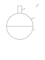
- FIG. 1 is a schematic view of a molding die according to the present embodiment.
- FIG. 2 is a schematic cross-sectional view of the molding die according to the present embodiment.
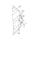
- FIG. 3 is a partially enlarged view of FIG.
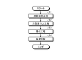
- FIG. 4 is a flowchart illustrating a method of molding a ceramic material according to the present embodiment.
- FIG. 5 is a diagram illustrating a step of obtaining a cured product having a desired shape.
- FIG. 6 is a flowchart illustrating a method for manufacturing a ceramic article according to the present embodiment.
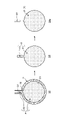
- FIG. 7 is a schematic view of the ceramic article according to the present embodiment.
- FIG. 8 is a diagram schematically showing a CT image of the ceramic article according to the present embodiment.
- FIG. 1 is a schematic view of a molding die according to the present embodiment.
- FIG. 2 is a schematic cross-sectional view of the molding die according to the present embodiment.
- the molding die 10 according to the present embodiment is a mold in which a ceramic material is filled therein and a cavity C for obtaining a cured product having a desired shape is formed. It can be said that the molding die 10 is formed of a soluble resin and the cavity C is covered with the mold made of the soluble resin.
- the mold 10 is soluble in a non-aqueous solvent.
- the soluble resin used in the molding die 10 is a resin that dissolves in a non-aqueous solvent.
- a description of the non-aqueous solvent will be described later.
- the molding die 10 preferably has a dissolution rate in a non-aqueous solvent of 1 ⁇ m / min to 80 ⁇ m / min, more preferably 5 ⁇ m / min to 30 ⁇ m / min, and 6 ⁇ m / min to 15 ⁇ m / min. Is more preferable. When the melting rate is within this range, the molding die 10 can be appropriately melted and demolded.
- the melting rate of the molding die 10 refers to a value obtained by dividing the thickness ( ⁇ m) of the molding die 10 to be melted by time.
- the method for measuring the dissolution rate of the molding die 10 is arbitrary, but it may be measured by the following method.
- the ceramic material is cured in the molding die 10 having a thickness of 1.6 mm, and the molding die 10 is immersed in methylene chloride having a temperature of 25 ° C. Then, the time at which all the molding molds 10 are completely dissolved is measured and used as the dissolution time, and the value obtained by dividing 1.6 mm by the dissolution time is used as the dissolution rate.
- the numerical range represented by "-" means a numerical range including the numerical values before and after "as the lower limit value and the upper limit value", and when "-" is used thereafter, it means the same meaning.
- the molding die 10 does not melt due to heating during curing of the ceramic material in the cavity C.
- the melting point of the molding die 10 is preferably 70 ° C. or higher, and may be 80 ° C. to 250 ° C., or 100 ° C. to 230 ° C. Further, the melting point of the molding die 10 may be 100 ° C. or higher, 120 ° C. to 250 ° C., or 150 ° C. to 230 ° C. When the melting point of the molding die 10 is in this range, the molding die 10 is suppressed from melting during molding, and a cured product having a desired shape can be appropriately obtained.
- the molding die 10 has an elastic modulus of 500 MPa to 5000 MPa, preferably 700 MPa to 4000 MPa, and more preferably 1100 MPa to 2600 MPa.
- the elastic modulus here is a tensile elastic modulus, that is, Young's modulus, and may refer to, for example, a value under the conditions of 23 ° C. and a relative humidity of 0% ° C.
- the molding die 10 preferably has a tensile strength of 500 MPa to 5000 MPa, more preferably 1000 MPa to 3000 MPa.
- the tensile strength here may refer to a value under the conditions of, for example, 23 ° C. and a relative humidity of 0% ° C.
- the shape of the molded body is not deformed to the extent that it can be formed into a desired shape, and the shape of the molding material is stabilized until the molding material is cured (gelled). Can be held.
- Tensile strength and tensile modulus can be measured by ISO 527-1 and ISO 527-2.
- the mold 10 has a thermal conductivity of 0.05 [W / mK] to 0.40 [W / mK] and 0.08 [W / mK] to 0.30 [W / mK]. Is preferable, and it is more preferably 0.1 [W / mK] to 0.2 [W / mK].
- the thermal conductivity can be measured by, for example, JIS A1412-2.
- the soluble resin used in the mold 10 is mainly composed of at least one material selected from the group consisting of polystyrene, ABS (Acrylonitrile-Butadiene-Stylerene) resin, acrylic resin, polycarbonate, epoxy resin, and polyester. Is preferable. Further, it is more preferable that the soluble resin used in the molding die 10 contains polystyrene as a main component.
- polystyrene for example, by using a soluble resin used in the molding die 10 such as toyostyrene impact-resistant polystyrene H350 as such a material, the above-described characteristics can be appropriately imparted to the molding die 10. .
- the main component here means, for example, that the ratio of the material to the whole of the molding die 10 is 50% or more by mass ratio, preferably 80% or more, and more preferably 95% or more.
- the molding die 10 does not have a film or the like formed on the inner surface of a component other than the soluble resin. That is, in the molding die 10, it is preferable that the soluble resin is not completely covered by the coating film of other components on the inner surface side, and the soluble resin is exposed in at least a part of the inner surface, and the inner surface is preferably exposed. It is preferable that the soluble resin is exposed over the entire area. If a film of a component other than the soluble resin is present on the inner surface of the molding die 10, it may remain undissolved when the soluble resin as the main component is dissolved, and the film may need to be removed in another step. Therefore, if the film is not present or is present in a small amount, the productivity is improved, which is preferable. Further, if the film is an unnecessary component for the finally obtained ceramic material, it is preferable that it does not remain.
- the molding die 10 is composed of two or more divided bodies, and the divided bodies are fitted together. As shown in FIGS. 1 and 2, in the present embodiment, the molding die 10 includes the first divided body 12 and the second divided body 14. An injection port portion 16 is connected to the first divided body 12.
- a first cavity (space) C1a is formed inside the first divided body 12. Since the portion of the first divided body 12 to be fitted with the second divided body 14 is not covered with the member (soluble resin), the first cavity C1a includes the first divided body 12 and the second divided body 14. It is open when it is not fitted.
- a first cavity (space) C1b is formed inside the second divided body 14. Since the portion of the second divided body 14 to be fitted with the first divided body 12 is not covered with the member (soluble resin), the first cavity C1b is formed by the first divided body 12 and the second divided body 14. It is open when it is not fitted.
- a second cavity (space) C2 is formed inside the injection port portion 16. Since the inlet portion 16 has an open end on the side connected to the first divided body 12, the second cavity C2 and the first cavity C1a are the first divided body 12 and the second cavity C2. It communicates through the connection point of. Further, the injection port 16a has an injection port 16a open at an end portion on the side opposite to the side connected to the first divided body 12. Therefore, the second cavity C2 and the first cavity C1a communicate with the outside via the injection port 16a. Further, on the inner peripheral surface of the connection portion between the injection port portion 16 and the first divided body 12, in other words, a constriction 18 is formed between the second cavity C2 and the first cavity C1a.
- the constriction 18 is a protruding portion that protrudes inward in the radial direction from the inner peripheral surface of the connection portion between the injection port portion 16 and the first divided body 12. Therefore, when viewed from the axial direction of the injection port portion 16, the opening area of the portion between the second cavity C2 and the first cavity C1a (the portion where the constriction 18 is formed) is the opening area of the second cavity C2. And smaller than the opening area of the first cavity C1a.
- the shape of the injection port portion 16 is not limited to the above description and may be arbitrary. Further, the constriction 18 is not an essential configuration and may not be provided.
- the first cavity C1a is formed inside the first divided body 12
- the first cavity C1b is formed inside the second divided body 14
- the second cavity C1b is formed inside the injection port portion 16.
- Cavity C2 is formed.
- the first cavity C1a, the first cavity C1b, and the second cavity C2 communicate with each other to form the cavity C. That is, the cavity C includes a first cavity C1a, a first cavity C1b, and a second cavity C2.
- the portions formed by the first cavities C1a and the first cavities C1b are shaped so as to give the cured body a desired shape. That is, assuming that the portion formed by the first cavity C1a and the first cavity C1b is the first cavity C1, the first cavity C1 has a shape such that the cured body has a desired shape.
- the first cavity C1 is spherical in the present embodiment, and the obtained cured body, molded body, and sintered body are also spherical.
- the first cavity C1 is not limited to a spherical shape and may have an arbitrary shape.
- the molding die 10 since the molding die 10 is demolded by dissolving the molding die 10 with a non-aqueous solvent, the cavity has a complicated shape with many irregularities or intricate shape, and damage such as a constriction or a fine line shape. Even when it has a shape that is easy to form, a cured product, a molded product, and a sintered body that retain the desired shape can be stably obtained without impairing the desired shape.
- the first cavity C1 includes the first cavity C1a and the first cavity C1b, and can be said to be a cavity formed inside the fitted first divided body 12 and the second divided body 14.
- the portion of the second cavity C2 in the cavity C communicates with the first cavity C1 and is provided with an injection port 16a. It can be said that the second cavity C2 is a portion for injecting a ceramic material into the first cavity C1.
- the molding die 10 preferably has one injection port for injecting a ceramic material. This is because when the injection of the ceramic material is completed, it can be easily sealed by closing only one injection port. However, a plurality of injection ports may be provided. When there is only one injection port, it is preferable that the number of processes for obtaining a desired shape is small in the vicinity of the injection port of the molded body or the sintered body. When there are a plurality of injection ports, it is preferable in terms of uniform injection of the ceramic casting liquid and improvement of productivity, but it may be necessary to process a plurality of locations in the vicinity of the injection port in the molded body or sintered body.
- the thickness of the portion of the molding die 10 that forms the first cavity C1 is defined as the thickness D1.
- the thickness D1 is preferably 0.5 mm to 3.0 mm, more preferably 0.6 mm to 2.0 mm, and even more preferably 0.8 mm to 1.6 mm. Since the thickness D1 of the molding die 10 is in this range, the molding die 10 can be appropriately melted at the time of demolding while maintaining the strength at the time of molding.
- the thickness D1 can also be said to be the length from the inner peripheral surface to the outer peripheral surface of the portion forming the first cavity C1.
- the thickness D1 is the thickness from the inner peripheral surface 12a to the outer peripheral surface 12b of the first divided body 12, and is the thickness from the inner peripheral surface 14a to the outer peripheral surface 14b of the second divided body 14. It can be said that.
- the arithmetic mean roughness Ra specified in JIS B 0601: 2001 on the inner surface of the portion of the molding die 10 forming the first cavity C1 is preferably 0.01 ⁇ m or more and 5 ⁇ m or less, preferably 0.05 ⁇ m or more and 1 ⁇ m. It is more preferably 0.1 ⁇ m or more, and further preferably 0.5 ⁇ m or less.
- the surface roughness of the inner surface of the first cavity C1 is within this range, the dimensional accuracy and surface flatness of the cured product can be ensured, and the appearance defect can be suppressed.
- the inner surface of the portion forming the first cavity C1 is the inner peripheral surface 12a of the first divided body 12, and can be said to be the inner peripheral surface 14a of the second divided body 14.
- the volume of the second cavity C2 is preferably 0.5% by volume to 5% by volume, more preferably 0.8% by volume to 4% by volume, based on the volume of the first cavity C1. It is more preferably 1% by volume to 3% by volume. When the volume of the second cavity C2 is within this range, even when the ceramic material is cured and shrunk, the ceramic material filled in the second cavity C2 is drawn into the first cavity C1, and the dimensional accuracy of the cured body is appropriate. Can be secured to.
- FIG. 3 is a partially enlarged view of FIG. FIG. 3 shows a fitting portion between the first divided body 12 and the second divided body 14.
- the first divided body 12 includes a main body portion 12A and a protruding portion 12B.
- the main body portion 12A is a portion forming the first cavity C1a, and in the example of the present embodiment, the main body portion 12A is a hollow hemispherical member in which the portion on the side fitted to the second divided body 14 is open.
- the protruding portion 12B projects from the end portion 12Aa of the main body portion 12A on the side fitted to the second divided body 14 to the side fitted to the second divided body 14.
- the protruding portion 12B is provided so that the inner peripheral surface of the protruding portion 12B and the inner peripheral surface of the main body portion 12A are integrated. That is, the inner peripheral surface of the protruding portion 12B and the inner peripheral surface of the main body portion 12A form the inner peripheral surface 12a of the first divided body 12.
- the protruding portion 12B is provided so that the outer peripheral surface of the protruding portion 12B is located on the inner peripheral surface 12a side (inner in the radial direction) with respect to the outer peripheral surface of the main body portion 12A. That is, the outer peripheral surface of the main body portion 12A forms the outer peripheral surface 12b of the first divided body 12.
- FIG. 3 is a cross-sectional view showing only a part in the circumferential direction
- the protruding portion 12B is formed over the entire area of the main body portion 12A in the circumferential direction.
- the second divided body 14 includes a main body portion 14A and a protruding portion 14B.
- the main body portion 14A is a portion forming the first cavity C1b, and in the example of the present embodiment, the main body portion 14A is a hollow hemispherical member in which the portion on the side fitted to the first divided body 12 is open.
- the protruding portion 14B protrudes from the end portion 14Aa of the main body portion 14A on the side fitted to the first divided body 12 to the side fitted to the first divided body 12.
- the protruding portion 14B is provided so that the outer peripheral surface of the protruding portion 14B and the outer peripheral surface of the main body portion 14A are integrated.
- the outer peripheral surface of the protruding portion 14B and the outer peripheral surface of the main body portion 14A form the outer peripheral surface 14b of the second divided body 14.
- the protruding portion 14B is provided so that the inner peripheral surface of the protruding portion 14B is located on the outer peripheral surface 14b side (outer in the radial direction) with respect to the inner peripheral surface of the main body portion 14A. That is, the inner peripheral surface of the main body portion 14A forms the inner peripheral surface 14a of the second divided body 14.
- the protruding portion 14B is formed over the entire area of the end portion 14Aa in the circumferential direction.
- FIG. 3 is a cross-sectional view showing only a part in the circumferential direction
- the protruding portion 14B is formed over the entire area of the main body portion 14A in the circumferential direction.
- the first division body 12 and the second division body 14 are such that the protrusion 12B of the first division body 12 is inserted inside the protrusion 14B of the second division body 14. It is fitted.
- the tip portion 12Ba of the protruding portion 12B of the first divided body 12 is radially inside the protruding portion 14B of the second divided body 14. , Contact with the end portion 14Aa of the main body portion 14A of the second split body 14.
- tip portion 14Ba of the protruding portion 14B of the second divided body 14 comes into contact with the end portion 12Aa of the main body portion 12A of the first divided body 12 on the radial outer side of the protruding portion 12B of the first divided body 12.
- the thickness D2 of the protruding portion 12B is preferably 0.5 mm to 2.0 mm, more preferably 0.7 mm to 1.5 mm, and even more preferably 0.8 mm to 1 mm.
- the thickness D2 is within this range, the alignment between the tip portion 12Ba of the protruding portion 12B and the end portion 14Aa of the main body portion 14A is ensured, and a gap is formed between the first divided body 12 and the second divided body 14. Can be suppressed. As a result, it is possible to appropriately manufacture the cured product by suppressing the entry of outside air into the inside of the molding die 10.
- the thickness D2 of the protruding portion 12B is within the above numerical range, it is possible to prevent the protrusion 12B from becoming too thin and to secure the strength.
- the thickness D2 can be said to be the thickness in the normal direction of the portion where the divided bodies are fitted to each other, and can also be said to be the thickness of the member on the inner peripheral surface side at the portion where the divided bodies are fitted to each other.
- the first divided body 12 and the second divided body 14 are fitted as described above, but the fitting structure is not limited to that described above.
- the protruding portion 12B formed on the inner peripheral surface side is provided on the first divided body 12 side
- the protruding portion 14B formed on the outer peripheral surface side is provided on the second divided body 14 side.
- the protrusion 12B was inserted into the protrusion 14B, but the present invention is not limited to this.
- a protrusion formed on the inner peripheral surface side is provided on the second divided body 14 side
- a protrusion formed on the outer peripheral surface side is provided on the first divided body 12 side
- the second divided body is provided.
- the protrusion on the 14 side may be inserted into the protrusion on the 12 side of the first divided body.
- the molding die 10 has the above configuration.
- the molding die 10 is not limited to the configuration described above.
- the molding die 10 may be an integrally formed mold, for example, instead of a configuration including a plurality of divided bodies.
- the molding die 10 can be manufactured by an arbitrary method so as to have a cavity C having a desired shape.
- Examples of the molding method of the molding die 10 include melt molding.
- the melt molding is a method in which the material of the molding die 10 is melted, molded into a desired shape, and cured.
- examples of the molding method of the molding die 10 include injection molding, blow molding and the like.
- FIG. 4 is a flowchart illustrating a method of molding a ceramic material according to the present embodiment.
- the raw material mixing step is a step of mixing a ceramic powder having a desired composition with a resin, a curing agent and a solvent to obtain a slurry-shaped ceramic material (hereinafter referred to as a ceramic casting liquid) (S1).
- the ceramic powder is not particularly limited as long as it becomes ceramic by sintering, and examples thereof include known ceramic powder.
- examples of the ceramic powder include aluminum oxide, zirconium oxide, silicon oxide, silicon nitride, silicon carbide, aluminum nitride, and sialon. One of these may be used alone, or two or more thereof may be mixed and used.
- the ceramic powder preferably has a 50 % particle size D50 of less than 1.0 ⁇ m so that a stable sintered body can be obtained in the sintering step described later. If the 50% particle size D 50 is 1.0 ⁇ m or more, molding defects may occur due to particle settling in the slurry, which may lead to a decrease in sintering density.
- the 50% particle size D50 is more preferably less than 0.9 ⁇ m, still more preferably less than 0.8 ⁇ m. Further, a particle size D 50 of 0.1 ⁇ m or more is preferable because it facilitates scattering, clogging prevention and procurement during handling.
- the structure obtained by sintering is a bonded phase in which the main phase crystal particles containing silicon nitride as a main component are vitreous and / or crystalline. It is preferable that the form is combined with.
- the ceramic powder When silicon nitride is used as the ceramic powder, the ceramic powder preferably has a silicon nitride pregelatinization rate of 70% or more, more preferably 80% or more, still more preferably 90% or more.
- the silicon nitride powder has a pregelatinization rate of less than 70%, the effect of incorporating the needle-like structure during the phase transition from ⁇ to ⁇ during sintering cannot be sufficiently obtained, and the strength of the sintered body decreases. If the silicon nitride powder has a pregelatinization rate of 90% or more, a sufficient incorporation effect can be obtained and a sintered body having high strength, particularly toughness, can be obtained.
- the content of silicon nitride having such a pregelatinization rate in the ceramic powder is preferably 85% by mass or more, more preferably 92% by mass or more.
- a sintering aid for improving sintering is added to the ceramic powder.
- Group 2 alkaline earth metal
- Group 3 rare earth (scandium group)
- Group 4 titanium group
- Group 5 earth metal (vanadium group)
- 13th group as sintering aids
- the content in the ceramic powder is 1 in terms of oxide. It is preferably mass% to 15% by mass, more preferably 2% by mass to 8% by mass.
- the content of the sintering aid is small, but if it is less than 1% by mass, sintering may become difficult.
- the resin is a component for molding a ceramic material into a desired shape in a curing step described later, and examples thereof include known curable resins.
- a resin that is required to have shape retention in the curing step and forms a three-dimensional network structure by a polymerization reaction is used.
- the resin is preferably liquid in that it enhances the fluidity of the ceramic casting liquid and has good filling property into the molding mold 1 described later.
- the resin can be easily removed from the ceramic molded product in the degreasing step after the curing step and before sintering.
- the resin used in this embodiment include epoxy resin, phenol resin, melamine resin, acrylic acid resin, urethane resin and the like. Among them, epoxy resin is preferably used because it has good shape retention.
- the epoxy resin include glycidyl ether type epoxy resin of bisphenols such as bisphenol A type and bisphenol F type, phenol novolac type epoxy resin, cresol novolac type epoxy resin, glycidylamine type epoxy resin, and glycidyl such as aliphatic epoxy resin.
- the resin added to the ceramic casting liquid is preferably a material different from the soluble resin of the molding die 10.
- the average molecular weight of the epoxy resin is preferably 20,000 to 30,000.
- the average molecular weight of the epoxy resin is more preferably 50 to 3000, still more preferably 50 to 2500, in that the resin and the powder can be easily mixed and a constant mechanical strength can be obtained.
- the curing agent cures the resin and is selected according to the resin used.
- the curing agent is preferably water-soluble and rapidly cures the resin, and examples thereof include amine-based curing agents, acid anhydride-based curing agents, and polyamide-based curing agents.
- the amine-based curing agent is preferable in that the reaction is rapid, and the acid anhydride-based curing agent is preferable in that a cured product having excellent heat impact resistance can be obtained.
- Examples of the amine-based curing agent include aliphatic amines, alicyclic amines, aromatic amines, and any of monoamines, diamines, triamines, and polyamines can be used.
- Examples of the acid anhydride-based curing agent include methyltetrahydrophthalic anhydride and dibasic acid polyanhydride.
- the solvent adjusts the viscosity of the mixture of the raw materials to be used to form a slurry, which facilitates filling of the ceramic casting liquid into the molding die 10 described later.
- the solvent for example, water ( H2O ), alcohols, and other organic solvents can be used. Among them, the water system is preferable from the viewpoint of manufacturing cost and environmental load.
- the selection of the resin and the solvent should be a combination having a good affinity between the resin and the solvent in order to facilitate the removal of the resin in the degreasing step described later. If the affinity between the resin and the solvent is poor, the resin and the solvent may separate and segregate inside the molded product, which may cause defects such as pores during sintering.
- the above-mentioned ceramic powder, resin, curing agent and solvent are mixed to prepare a ceramic casting liquid. If necessary, a dispersant or the like is added. At this time, mixing may be performed by a known method, for example, a dissolver, a homomixer, a kneader, a roll mill, a sand mill, a ball mill, a bead mill, a vibrator mill, a high-speed impeller mill, an ultrasonic homogenizer, a shaker, a planetary mill, and a self-revolution. Examples include mixers and in-line mixers.
- a pH adjuster As the dispersant to be added as needed, a pH adjuster, a surfactant, a polymer dispersant, etc. can be appropriately selected and added in order to dissociate and further disperse the agglomerates of the ceramic powder.
- the pH adjuster, surfactant, polymer dispersant and the like are preferably those that do not adversely affect the gelation of the above-mentioned curable resin.
- a basic organic substance can be used, for example, alkanolamines such as ammonia, monoethanolamine, diethanolamine and triethanolamine, choline, guanidines, tetramethylammonium hydroxide and the like 4 Examples include grade ammonium salts.
- inorganic acids, organic acids and salts thereof can be used, for example, phosphoric acid, nitric acid, citric acid, malic acid, acetic acid, lactic acid, oxalic acid, tartrate acid and the like, salts thereof, amino acids. Androgynous salts and the like can be mentioned.
- surfactant examples include alkylamine salts, aliphatic or aromatic quaternary ammonium salts, heterocyclic quaternary ammonium salts such as pyridinium and imidazolium, phosphonium or sulfonium salts containing an aliphatic or heterocycle, and acetylene. Glycol and the like can be mentioned.
- polymer dispersant examples include polymers having a primary to tertiary amine, a quaternary ammonium base, a quaternary phosphonium base, etc. in the polymer main chain or side chain, acrylic acid, a homopolymer of a salt thereof, and water-soluble.
- examples thereof include a sex aminocarboxylic acid-based polymer and a (co) polymer of an acrylic acid ester.
- pH adjusters may be used alone or in combination of two or more.
- the resin-added slurry containing the resin and the curing agent-added slurry containing the curing agent are separately prepared.
- the separately prepared slurries may be mixed at the time of use.
- the ceramic powder may be mixed with either slurry or both slurries, separately from both slurries.
- a slurry containing ceramic powder may be prepared separately.
- a ceramic casting liquid is prepared using the raw material slurry which is the above-mentioned raw material mixture.
- the viscosity of the ceramic casting liquid may be any viscosity as long as it can be easily filled in the casting liquid injection step described later.
- the viscosity at a shear rate of 10 [1 / s] is preferably 50 Pa ⁇ s or less, preferably 20 Pa. -S or less is more preferable.
- the viscosity of the ceramic casting liquid is more preferably in the range of 0.1 Pa ⁇ s to 10 Pa ⁇ s.
- the viscosity of the ceramic casting liquid can be easily adjusted by adjusting the amount of solvent used and the amount of resin added in the raw material used.
- air or the like may be entrained by mixing in the raw material mixing step, and gas may be contained in the obtained ceramic casting liquid. Therefore, if necessary, a defoaming step for removing the gas contained in the ceramic casting liquid is performed before the casting liquid injection step, which is the next step. If gas is contained in the ceramic casting liquid, pores due to air bubbles may be generated inside in the curing step and may remain in the ceramic article obtained by firing.
- the ceramic casting liquid may be defoamed under reduced pressure, and a defoaming pump (vacuum pump), a defoaming mixer, or the like is used. Defoaming may be performed, for example, for 1 minute to 120 minutes under a reduced pressure of 0.6 kPa to 10 kPa.
- a defoaming mixer the raw material mixing step and the defoaming step can be carried out at the same time.
- the defoaming mixer include a rotation / revolution mixer equipped with a vacuum pump, a planetary mixer, and the like.
- the casting liquid injection step is a step of injecting the ceramic casting liquid obtained through the raw material mixing step and, if necessary, the defoaming step into the molding die 10 (S2).
- the ceramic casting liquid is injected into the cavity C from the injection port 16a.
- it is preferable to inject the ceramic casting liquid so that the ceramic casting liquid is filled in the first cavity C1 and the second cavity C2 of the cavities C.
- a device capable of sending the ceramic casting liquid and supplying it into the molding mold 10 may be used.
- a pump such as a diaphragm pump, a tube pump, or a syringe pump may be used.
- a rotary positive displacement diaphragm pump equipped with a precision constant velocity cam having a structure that does not generate pulsation is preferable.
- an in-line mixer or the like that can send a liquid while mixing raw materials to prepare a ceramic casting liquid can also be used. When using an in-line mixer, the raw material mixing step and the casting liquid injection step can be performed at the same time.
- both slurries can be mixed and immediately sent to the molding die 10 for filling, which is preferable. ..
- a two-component mixing / discharging device may be used.
- a method of discharging with a constant capacity cylinder may be used, or a valve switching method using a mono pump that suppresses pulsation may be used.
- a separate mixer may be used as the slurry mixing device.
- the resin component in the ceramic casting liquid is cured to cure the ceramic material into a desired shape (S3).
- the ceramic casting liquid is cured under desired curing conditions according to the characteristics of the ceramic casting liquid.
- the reaction starts from the time when the resin-added slurry and the curing agent-added slurry are mixed and cured, so that it may be left for a predetermined time.
- the curing time is about 1 hour to 3 days, preferably 1 hour to 24 hours from the viewpoint of production efficiency, and more preferably 1 hour to 12 hours.
- the heating temperature for curing the resin is preferably in the range of 30 ° C to 85 ° C, more preferably in the range of 40 ° C to 70 ° C, and in the range of 50 ° C to 60 ° C. It is more preferable to have.
- the heating time that is, the time for maintaining the heating temperature is preferably 5 minutes to 2880 minutes, more preferably 10 minutes to 1440 minutes, and further preferably 30 minutes to 180 minutes.
- the demolding step is a step of taking out the cured body of the ceramic material cured in the curing step from the molding die 10 (S4).
- the molding die 10 is brought into contact with a non-aqueous solvent, the molding die 10 is dissolved in the non-aqueous solvent, and the cured product is demolded.
- the contact with the non-aqueous solvent is preferably immersed in the non-aqueous solvent. If immersion in a non-aqueous solvent is used to dissolve the molding die 10, the molding die 10 in which the ceramic material is cured inside can be easily removed by simply leaving the molding die 10 in the non-aqueous solvent.
- the non-aqueous solvent is a liquid whose main component is a component other than water, and dissolves the soluble resin of the molding die 10.
- the non-aqueous solvent is preferably a solvent that dissolves the soluble resin of the molding die 10 and does not dissolve the resin in the ceramic casting liquid.
- the main component is at least one material selected from the group consisting of methylene chloride, d-limonene, acetone, and toluene.
- the main component here means, for example, that the ratio of the material to the whole non-aqueous solvent is 50% or more.
- the mold 10 is dissolved in a non-aqueous solvent in a temperature environment lower than the heating temperature at which the resin in the ceramic casting liquid is cured in the curing step to demold the cured product. Is preferable. Furthermore, in the demolding step, it is preferable to dissolve the molding die 10 in a non-aqueous solvent in an environment of 10 ° C. to 40 ° C. to demold the cured product. By demolding at a relatively low temperature in this way, it is possible to suppress heating of the cured product more than necessary, and to produce an appropriate ceramic article.
- the demolding time that is, the time for contacting the molding die 10 with the non-aqueous solvent is preferably 20 minutes to 1800 minutes, more preferably 30 minutes to 240 minutes, and 60 minutes to 180 minutes. Is even more preferable. By setting the demolding time within this range in this way, the molding die 10 can be appropriately melted and appropriately demolded.
- the demolding step may proceed at the same time as the curing step described above. That is, the demolding step may be performed immediately after injecting the ceramic casting liquid into the molding die 10. In this case, the molding die 10 filled with the ceramic casting liquid is immediately contacted with the non-aqueous solvent immediately after the ceramic casting liquid is filled, and the melting of the molding die 10 proceeds. At this time, the curing (gelling) of the ceramic casting liquid is allowed to proceed at the same time as the melting of the molding die 10.
- the molding die 10 is manufactured so that the exposure melting time of the molding die 10 is longer than the curing time of the ceramic casting liquid (curing time ⁇ exposure melting time). By adjusting both the curing time and the exposure melting time, the molding die 10 is melted (a part of the cured body inside is exposed) after the ceramic casting liquid is cured, and a cured body having a desired shape can be obtained. ..
- the curing time means the time from immediately after the ceramic casting liquid is adjusted until the ceramic casting liquid can maintain the shape of the molding mold by gel curing, and the exposure melting time means that the molding mold 10 is immersed in a non-aqueous solvent. It means the time from when it is made until a part of the cured body inside it is exposed.
- curing time means a cured product in which the ceramic casting liquid is a viscoelastic solid as the formation of a three-dimensional network structure progresses due to the polymerization reaction of the resin and the curing agent in the ceramic casting liquid. It is the time until it has sufficient hardness to withstand handling.
- the cured product is not hardened to a predetermined hardness or higher before the demolding step or the cured product after the demolding is advanced to the drying step, the cured product may be deformed or cracked.
- the hardness that can be said to be sufficient for handling is appropriately determined by the shape and dimensions, but the "hardness that can be said to be sufficient for handling" in the present specification means that the cured product has a bending elastic modulus of 2 MPa or more. Is.
- a round bar cured product for destructive inspection is subjected to a predetermined elapsed time (for example, 5 minutes, 10 minutes, 15 minutes, 20 minutes, 30 minutes).
- the measurement conditions are as follows.
- the flexural modulus in the 3-point bending test is calculated from the load-elongation graph using the tangential method that takes any two points from the initial gradient of the straight part.
- L is the distance between fulcrums (mm)
- D is the sample diameter (mm)
- Fmax is the maximum load d (N)
- ⁇ F is the amount of change in bending load (N)
- ⁇ S is the amount of change in elongation (N). Is.
- the curing time and exposure dissolution time can be adjusted by adjusting the temperature of the non-aqueous solvent used for demolding, the type of molding mold 10 (type of resin and curing agent, amount of addition, etc.), thickness, and the like.
- the present embodiment may include a step of removing a part of the cured product after demolding the cured product by a demolding step to obtain a cured product having a desired shape.
- FIG. 5 is a diagram illustrating a step of obtaining a cured product having a desired shape.
- the ceramic casting liquid is cured in the molding die 10 to form the cured product P in the molding die 10. Since the ceramic casting liquid is injected into the first cavity C1 and the second cavity C2 in the molding die 10, the cured product P is the cured product P1 which is a portion injected into the first cavity C1 and cured. 1 Includes a cured body P2 which is a portion injected into the cavity C1 and cured.
- the demolding step step S4
- the molding die 10 is melted to obtain a cured product P demolded from the molding die 10.
- a constriction 18 is formed between the first cavity C1 and the second cavity C2. Therefore, the portion between the cured product P1 and the cured product P2 corresponding to the constriction 18 is a constricted portion having a diameter smaller than that of the cured product P2.
- the cured body P2 is removed from the cured body P starting from the constricted portion between the cured body P1 and the cured body P2, and the cured body P1 is cured into a desired shape. Get as a body.
- the method for manufacturing a ceramic article includes a drying step of drying a cured product obtained by the above-mentioned molding method of a ceramic material to form a molded body, a degreasing step of degreasing the molded body to obtain a degreased body, and sintering the degreased body. It has a sintering process for forming a sintered body.
- FIG. 6 is a flowchart illustrating a method for manufacturing a ceramic article according to the present embodiment.
- the method for manufacturing a ceramic article according to the present embodiment includes a raw material mixing step (step S1), a casting liquid injection step (step S2), a curing step (step S3), and a demolding step. It has (step S4), a drying step (step S5), a degreasing step (step S6), and a baking step (step S7).
- step S1 the raw material mixing step to the demolding step
- steps S1 to S4 are the same as the molding method of the ceramic material, the description thereof will be omitted.
- the drying step is a step of removing water, a volatile solvent, and the like from the cured product obtained in the demolding step and drying the cured product to obtain a molded product (step S5).
- the cured product is slowly dried so as not to cause cracks or the like. That is, the cured product is dried while preventing cracks and the like due to shrinkage stress caused by the difference in drying speed between the surface and the inside of the cured product.
- the moisture contained in the cured product over a long period of time under relatively mild conditions such as 25 ° C to 50 ° C, relative humidity 50% to 95%, 48 hours to 7 days, etc. Remove.
- the drying step is preferably carried out until the water content of the cured product is 20% or less of the mass at the time of absolute drying.
- the degreasing step is a step of removing the resin, the non-volatile solvent and the like from the molded body obtained in the drying step to obtain a degreased body (step S6).
- a degreased body step S6
- most of the components that inhibit sintering are removed in the sintering step of the next step. If a large amount of components that inhibit sintering remain, pores may occur in the sintered body during sintering, or carbides may occur as by-products, making it impossible to obtain the characteristics required for the final product. There is a risk of.
- the temperature is slowly raised and maintained from 250 ° C. to 800 ° C., and the total processing time is contained in the molded product over a relatively long time such as 3 to 14 days. Removes resin components and the like.
- the degreasing step particularly for silicon nitride is preferably carried out until the amount of residual carbon in the molded product is 900 ppm or less.
- the amount of residual carbon is not limited to carbides such as silicon carbide (SiC).
- the firing step is a step of firing the degreased body that has undergone the degreasing step to sintered the ceramic material into a sintered body (ceramic article) (step S7).
- the ceramic material is sintered to form a sintered body, that is, a ceramic article, and a known firing method may be applied.
- the conditions of the firing step are not particularly limited as long as the firing step can be performed to obtain a sintered body.
- the firing is performed in a nitrogen atmosphere with an oxygen concentration of 50 ppm or less. preferable.
- the maximum firing temperature in the firing step is set to 1800 ° C. or lower at which silicon nitride begins to thermally decompose, and the maximum temperature is preferably in the range of 1650 ° C. to 1750 ° C.
- the firing time is preferably in the range of 240 minutes to 15 hours, and may be in the range of 240 minutes to 12 hours.
- the sintered body obtained in the firing step may be subjected to a secondary firing step in order to further obtain a sintered body having desired characteristics.
- This secondary firing step is a step of further applying a high pressure treatment to the sintered body obtained in the above-mentioned firing step (primary firing) to densify the structure of the sintered body.
- the high pressure treatment in this secondary firing step a hot isostatic pressing method (HIP), gas pressure firing, hot pressing, etc. can be used.
- HIP hot isostatic pressing method
- the sintered body obtained by sintering has high strength, and is preferably treated with HIP in the range of 1500 ° C to 1750 ° C and 50 MPa to 200 MPa.
- FIG. 7 is a schematic view of the ceramic article according to the present embodiment.
- the ceramic article (sintered body) manufactured by the method for manufacturing a ceramic article according to the present embodiment will be referred to as the ceramic article 100, and the characteristics of the ceramic article 100 will be described below.
- the ceramic article 100 is a sintered body of ceramics.
- the ceramic article 100 is preferably a sintered body of at least one ceramic of, for example, aluminum oxide, zirconium oxide, silicon oxide, silicon nitride, silicon carbide, aluminum nitride, and Sialon, and is a sintered body of silicon nitride. It is more preferable to have.
- the ceramic article 100 is a sintered body after the firing step and before polishing. That is, the surface of the sintered body may be polished after the firing step (sintering step), but the ceramic article 100 of the present embodiment is a sintered body in an unpolished state (state before polishing). Point to. However, the present invention is not limited to this, and the ceramic article 100 may refer to a sintered body in a state of being polished after sintering.
- the ceramic article 100 may be used for any purpose, and may be used, for example, as a bare ball for a bearing ball.
- the raw ball here means an intermediate product when the final product is a bearing ball, and for example, by polishing the surface of the ceramic article 100, the bearing ball which is the final product is formed.
- the ceramic article 100 is spherical.
- the sphere here is not limited to a true sphere, and for example, the ceramic article 100 is preferably true within 3%, more preferably within 2.5%, still more preferably within 2% with respect to the diameter D. It may be spherical.
- the sphericity is preferably 1.5 mm or less, more preferably 1.25 mm or less, still more preferably 1.0 mm or less.
- the sphericity is preferably 0.3 mm or less, more preferably 0.25 mm or less, still more preferably 0.2 mm or less.
- the diameter D here may refer to an average diameter (arithmetic mean value of the maximum and minimum values of the diameter).
- the ceramic article 100 is a sintered body of the cured product P1 from which the cured product P2 corresponding to the constricted portion of the molding die 10 has been removed, and there are cases where protrusions remain at the locations where the cured product P2 has been removed. be.
- the diameter D of the ceramic article 100 refers to the diameter measured at a position other than the protrusion on the surface 100a of the ceramic article 100.
- the arithmetic mean value of the maximum value and the minimum value of the diameter is the maximum value of the diameter of the ceramic article 100 measured at a place other than this protrusion and the diameter of the ceramic article 100 measured at a place other than this protrusion. Refers to the arithmetic mean value with the minimum of.
- the diameter D of the ceramic article 100 is preferably 0.5 mm or more and 80 mm or less, more preferably 30 mm or more and 55 mm or less, further preferably 45 mm or more and 55 mm or less, and 49 mm or more and 51 mm or less. More preferred. When the diameter is in this range, it can be suitably used for, for example, a bearing ball.
- the ceramic article 100 has a recess 102 formed on the surface 100a along the circumferential direction R. It can be said that the concave portion 102 is formed by manufacturing the ceramic article 100 by the manufacturing method of the present embodiment using the molding die 10 which is a split die.
- the circumferential direction R is the circumferential direction when the direction along the axis passing through the center of the ceramic article 100 is the axial direction and the circumferential direction when the direction along the axis passing through the center of the ceramic article 100 is the axial direction. Point in the direction.
- the circumferential direction in the vicinity is a circumferential direction deviated within 5% from the position in the circumferential direction when the direction along the axis passing through the center of the ceramic article 100 is taken as the axial direction.
- the recess 102 refers to a recessed portion of the surface 100a.
- the ceramic article 100 is not limited to the entire circumference of the circumferential direction R along the portion where the recess 102 is formed, but is a part of the entire circumference of the circumferential direction R along the portion where the recess 102 is formed. May not be dented or may be protruding.
- the recess 102 may be formed over the entire circumference of the circumferential direction R in the circumferential direction R of the surface 100a, and may be formed in a section of 50% or less with respect to the entire circumference of the circumferential direction R. It is more preferable that it is formed in a section of 25% or less with respect to the entire circumference of the circumferential direction R.
- the recess 102 may be formed in a section of 5% or more with respect to the entire circumference of the circumferential direction R in the circumferential direction R of the surface 100a, or may be formed in a section of 10% or more, or 15%. It may be formed by the above sections. That is, the recess 102 may be formed over the entire circumference of 5% or more of the circumferential direction R in the circumferential direction R of the surface 100a, and is 10% or more and 50% or less with respect to the entire circumference of the circumferential direction R. It may be formed in a section, or may be formed in a section of 15% or more and 25% or less with respect to the entire circumference of the circumferential direction R.
- the fact that the recess 102 is formed in a section of 50% or less with respect to the entire circumference of the circumferential direction R means that the recess 102 is continuously formed in a section of 50% or less with respect to the entire circumference of the circumferential direction R. It is not limited to being done.
- the recess 102 is formed intermittently along the circumferential direction R, and the total length of the recess 102 may be 50% or less with respect to the entire circumference of the circumferential direction R. The same may mean that the recess 102 is formed in a section of 25% or less with respect to the entire circumference of the circumferential direction R, or is formed in a section of 5% or more.
- the recess 102 is preferably formed along one circumferential direction R of the ceramic article 100.
- the ceramic article 100 does not have a plurality of recesses 102 extending along different circumferential directions R.
- a plurality of recesses 102 are formed in series along the same circumferential direction R.
- the recess 102 is located on the surface 100a at a position facing or facing a boundary position (see FIG. 3) between the inner peripheral surface 12a of the first divided body 12 and the inner peripheral surface 14a of the second divided body 14. It is formed in the vicinity.
- the circumferential direction R in which the recess 102 is formed is a portion facing or facing the boundary position between the inner peripheral surface 12a of the first divided body 12 and the inner peripheral surface 14a of the second divided body 14 on the surface 100a. It will be near the location. Since the ceramic article 100 can shrink through the firing step, the circumferential direction R in which the recess 102 is formed is the boundary between the inner peripheral surface 12a of the first divided body 12 and the inner peripheral surface 14a of the second divided body 14. It may shift to the vicinity of the location facing the position.
- FIG. 8 is a diagram schematically showing a CT image of the ceramic article according to the present embodiment.
- the depth A1 refers to the distance between the straight line L connecting one end point 102A and the other end point 102B of the recess 102 and the bottom 102C of the recess 102 in the CT (Computed Tomography) image of the ceramic article 100.
- the end point 102A refers to the boundary position on one side of the concave portion 102 and a portion other than the concave portion 102 on the surface 100a in the CT image of the ceramic article 100 in the direction along the surface 100a.
- the end point 102B points to the other side boundary position of the recess 102 and a portion other than the recess 102 on the surface 100a in the CT image of the ceramic article 100 in the direction along the surface 100a.
- the bottom portion 102C refers to the deepest portion (the portion located on the innermost side in the radial direction) of the recess 102 in the CT image of the ceramic article 100.
- the width A2 refers to the distance between the end points 102A and the end points 102B of the recess 102 in the CT image of the ceramic article 100.
- an InspecXio SMX-225CT manufactured by Shimadzu Corporation was used, and the ceramic article 100 was imaged under the conditions that the acceleration voltage was 150 kV, the acceleration current was 70 ⁇ m, and the Voxel size was 0.045 mm to 0.070 mm for the magnification. Point to the image.
- the depth A1 of the recess 102 has a length of 1% or less, preferably 0.1% or more and 1% or less, and 0.1% or more and 0.6% with respect to the diameter D of the ceramic article 100. It is more preferably 0.1% or more and 0.4% or less. That is, as the recess 102, the depth A1 is 1% or less, preferably 0.1% or more and 1% or less, more preferably 0.1% or more and 0.6% or less, still more preferably 0.1, with respect to the diameter D. A section of% or more and 0.4% or less may be formed over 5% or more of the entire circumference of the circumferential direction R of the ceramic article 100 or less, and 10% with respect to the entire circumference of the circumferential direction R of the ceramic article 100.
- the concave portion 102 may be formed in a section of 50% or more, or may be formed in a section of 15% or more and 25% or less with respect to the entire circumference of the circumferential direction R of the ceramic article 100.
- the convex portion is first scraped, then the burnt surface is removed, and the diameter is made uniform. Is needed.
- a polishing allowance for the convex portion is required, but in the case of a concave portion, the shaving allowance for the concave portion and the shaving allowance for removing the burnt surface of the surface and making the diameter uniform can be overlapped.
- the concave portion can have a smaller polishing allowance than the convex portion.
- the depth A1 of the recess 102 is preferably 0.5 mm or less, more preferably 0.05 mm or more and 0.3 mm or less, and further preferably 0.05 mm or more and 0.2 mm or less.
- the width A2 of the recess 102 is preferably 1% or less, more preferably 0.1% or more and 1% or less, and 0.1% or more and 0, with respect to the diameter D of the ceramic article 100. It is more preferably 6.6% or less, and further preferably 0.1% or more and 0.4% or less. That is, the width A2 of the recess 102 is preferably 1% or less, more preferably 0.1% or more and 1% or less, still more preferably 0.1% or more and 0.6% or less, still more preferably 0, with respect to the diameter D. .
- the section of 1% or more and 0.4% or less may extend over the entire circumference of 5% or more and the entire circumference of the ceramic article 100 with respect to the entire circumference of the circumferential direction R of the ceramic article 100.
- the width A2 of the recess 102 is preferably 0.5 mm or less, more preferably 0.05 mm or more and 0.3 mm or less, and further preferably 0.05 mm or more and 0.2 mm or less.
- the arithmetic mean roughness Ra specified by JIS B 0601: 2001 on the surface 100a at a portion other than the recess 102 and the protrusion is preferably 0.1 ⁇ m or more and 50 ⁇ m or less, preferably 0.5 ⁇ m or more and 20 ⁇ m or less. It is more preferably 1 ⁇ m or more and 10 ⁇ m or less.
- the arithmetic mean roughness Ra1 is calculated by extracting the roughness curve of the surface 100a by the reference length.
- the reference length is, for example, 0.8 mm.
- the molding method according to the present embodiment includes a step of mixing a ceramic powder, a sintering aid, a resin, a curing agent and a solvent to prepare a ceramic casting liquid to be a ceramic material, and a non-aqueous system.
- the step of injecting the ceramic casting liquid into the molding mold 10 which is soluble in a solvent and the cavity C is formed inside, and the resin in the ceramic casting liquid injected into the molding mold 10 are cured to be desired.
- the present invention includes a step of forming a cured product having the shape of the above, and a step of dissolving the molding die 10 in a non-aqueous solvent to demold the cured product.
- the mold 10 is formed of a soluble resin that is soluble in a non-aqueous solvent.
- the molding die 10 has an elastic modulus of 500 MPa to 5000 MPa and a thermal conductivity of 0.05 W / mK to 0.40 W / mK.
- a shape is formed by gel casting using a molding die 10. Since the accuracy is good, the surface texture is good, and the curing time is short, the productivity can be increased, so that the molded product can be appropriately molded and a good molded product can be obtained.
- the molding die 10 uses a member that can be dissolved in a non-aqueous solvent, it can be dissolved in a non-aqueous solvent and demolded, and the cured product can be demolded without applying stress. Damage can be suppressed.
- the molding die 10 having a high elastic modulus since the molding die 10 having a high elastic modulus is used, deformation during injection and curing can be suppressed, dimensional accuracy and surface flatness of the cured product can be maintained, and appearance defects can be suppressed. Further, since the molding die 10 having a relatively high thermal conductivity is used, it is possible to prevent external heat from being easily transferred to the ceramic casting liquid and to cure in a short time.
- the molding method according to the present embodiment it is preferable to use water as a solvent for the ceramic casting liquid. By using water, the cured product can be appropriately molded.
- the soluble resin of the molding die 10 contains at least one material selected from the group consisting of polystyrene, ABS resin, acrylic resin, polycarbonate, epoxy resin, and polyester as a main component. By using such a material, it becomes possible to appropriately mold the cured product while appropriately suppressing damage to the cured product during demolding.
- non-aqueous solvent it is preferable to use a solvent that can dissolve the soluble resin and does not dissolve the resin in the ceramic casting liquid. By using such a non-aqueous solvent, it is possible to appropriately mold the cured product while appropriately suppressing damage to the cured product during demolding.
- the heating temperature at which the resin in the ceramic casting liquid is cured is in the range of 30 ° C to 85 ° C. When the heating temperature is within this range, the ceramic casting liquid can be appropriately cured.
- this molding method it is preferable to dissolve the molding die 10 in a non-aqueous solvent in an environment of 10 ° C. to 40 ° C. to demold the cured product.
- a non-aqueous solvent in an environment of 10 ° C. to 40 ° C.
- the molding die 10 includes, as the cavity C, a first cavity C1 having a shape in which the cured product has a desired shape, and an injection port 16a for communicating with the first cavity C1 and filling the ceramic casting liquid. It is preferable that the cavity C2 is formed and a constriction 18 is formed between the first cavity C1 and the second cavity C2. In this case, in this molding method, starting from the portion corresponding to the constriction 18, the cured product is injected into the first cavity C1 and hardened (hardened body P1) and the cured product is injected into the second cavity C2 and cured.
- the cured body P2 has a step of breaking into (cured body P2) and obtaining a cured body P1 having a desired shape, which is a portion injected into the first cavity C1 and cured.
- this molding method by filling the ceramic casting liquid up to the second cavity C2, even when the ceramic material is cured and shrunk, the ceramic material filled in the second cavity C2 is drawn into the first cavity C1.
- the dimensional accuracy of the cured product can be appropriately guaranteed.
- the portion corresponding to the constriction 18 has a smaller diameter than the other portions and is easily broken. Therefore, the cured product P1 having a desired shape can be easily obtained by removing the cured product P2 filled in the second cavity C2 starting from the portion corresponding to the constriction 18.
- a ceramic article as a sintered body can be appropriately manufactured.
- the molding die 10 is formed of a soluble resin soluble in a non-aqueous solvent, and a ceramic material is filled therein to form a cavity C for obtaining a cured product having a desired shape. ..
- the molding die 10 has an elastic modulus of 500 MPa to 5000 MPa and a thermal conductivity of 0.05 W / mK to 0.40 W / mK. By using this molding die 10, it is possible to appropriately mold the cured product while suppressing damage to the cured product during demolding.
- the molding die 10 uses a member that can be dissolved in a non-aqueous solvent, it can be dissolved in a non-aqueous solvent and demolded, and the cured product can be demolded without applying stress. Damage can be suppressed. Further, since the molding die 10 having a high elastic modulus is used, deformation during injection and curing can be suppressed, dimensional accuracy and surface flatness of the cured product can be maintained, and appearance defects can be suppressed. Further, since the molding die 10 having a relatively high thermal conductivity is used, it is possible to prevent external heat from being easily transferred to the ceramic casting liquid and to cure in a short time.
- the soluble resin of the molding die 10 preferably contains at least one material selected from the group consisting of polystyrene, ABS (Acrylonitrile-Butadie-Stylene) resin, acrylic resin, polycarbonate, epoxy resin, and polyester as a main component. .. By using such a material, it becomes possible to appropriately mold the cured product while appropriately suppressing damage to the cured product during demolding.
- the non-aqueous solvent preferably contains at least one material selected from the group consisting of methylene chloride, d-limonene, acetone, and toluene as a main component.
- the molding die 10 is composed of two or more divided bodies, and the divided bodies are fitted together to form the molding die 10.
- the thickness D2 in the normal direction of the portion where the divided bodies are fitted to each other is 0.5 mm to 2.0 mm.
- the cavity C of the molding die 10 includes a first cavity C1 having a shape that makes the cured product a desired shape, and a second cavity C2 that includes an injection port 16a that communicates with the first cavity C1 and fills the ceramic material. It is preferable to include.
- the molding die 10 includes the first cavity C1 and the second cavity C2, so that the cured product can be appropriately molded.
- the volume of the second cavity C2 is preferably 1% by volume to 5% by volume with respect to the volume of the first cavity C1.
- the volume of the second cavity C2 is within this range, even when the ceramic material is cured and shrunk, the ceramic material filled in the second cavity C2 is drawn into the first cavity C1, and the dimensional accuracy of the cured body is appropriate. Can be secured to.
- the thickness D1 of the molding die 10 of the portion forming the first cavity C1 is 0.5 mm to 3.0 mm.
- the thickness D1 is in this range, it can be appropriately melted at the time of demolding while maintaining the strength at the time of molding.
- the arithmetic mean roughness Ra specified by JIS B 0601: 2001 on the inner surface of the molding die 10 of the portion forming the first cavity C1 is 0.01 ⁇ m or more and 5 ⁇ m or less.
- the surface roughness of the inner surface of the first cavity C1 is within this range, the dimensional accuracy and surface flatness of the cured product can be ensured, and the appearance defect can be suppressed.
- the molding die 10 can be melt-molded. Since the molding die 10 can be molded by melt molding, the molding die 10 can be easily manufactured.
- the ceramic article 100 according to the present embodiment is a sintered body of spherical ceramics, and a recess 102 is formed on the surface 100a along the circumferential direction R.
- the recess 102 has a depth of 1% or less with respect to the diameter D of the ceramic article 100.
- the ceramic article 100 according to the present embodiment is polished by forming the concave portion 102, as compared with the case where, for example, when the ceramic article 100 is polished, for example, convex portions are formed in all sections in the circumferential direction. The allowance can be reduced, the polishing process can be simplified, the life of the grindstone can be extended, and good properties can be obtained.
- the width A2 of the recess 102 is preferably 1% or less with respect to the diameter D of the ceramic article 100.
- the concave portion 102 having such a width is formed, for example, when polishing the ceramic article 100, for example, when a convex portion is formed in the entire section in the circumferential direction, etc.
- the polishing allowance can be reduced, the polishing process can be simplified, and the life of the grindstone can be extended, resulting in good properties.
- the recess 102 has a depth A1 of 0.1% or more and 1% or less with respect to the diameter of the ceramic article 100, and a width A2 of 0.1% or more and 1% or less with respect to the diameter of the ceramic article 100. It is preferable that the section has a length of 5% or more and not more than the entire circumference with respect to the entire circumference in the circumferential direction R of the ceramic article 100.
- the polishing allowance can be reduced, the polishing process can be simplified, and the grindstone can be used. The life of the ceramic can be extended and the properties are good.
- the diameter D of the ceramic article 100 is preferably 0.5 mm or more and 80 mm or less. When the diameter D is in this range, it can be suitably used for, for example, a bearing ball.
- Example 1 (Preparation of slurry ab) Silicon nitride powder (manufactured by Denka Co., Ltd., trade name SN-9FWS) 75.73 parts by mass, spinel powder 3.22 parts by mass as sintering aid, 19.36 parts by mass of water as solvent, fourth grade as dispersant 1.69 parts by mass of a 35% aqueous solution of ammonium salt (manufactured by Seichem) was mixed with a bead mill to prepare a silicon nitride slurry (slurry ab) as a base for the casting liquid. In the bead mill, silicon nitride balls (manufactured by Nikkato Corporation, diameter 1 mm) were used as the pulverizing medium.
- silicon nitride balls manufactured by Nikkato Corporation, diameter 1 mm
- a vacuum pump is installed with 99.19 parts by mass of the above slurry ab and 0.81 parts by mass of a curing agent (a mixture of triethylenetetramine and 2,4,6-tris (dimethylaminomethyl) phenol in a mass ratio of 2: 1).
- a curing agent a mixture of triethylenetetramine and 2,4,6-tris (dimethylaminomethyl) phenol in a mass ratio of 2: 1).
- a silicon nitride slurry (slurry a2) containing a curing agent was prepared by mixing with a rotating and revolving mixer. By the reduced pressure treatment (0.6 kPa), the slurry a2 did not contain bubbles of 10 ⁇ m or more.
- the slurry a1 was filled in the slurry tank 1 and the slurry a2 was filled in the slurry tank 2 so as to have the same volume. Subsequently, using two rotary positive displacement diaphragm pumps manufactured by Takumina Co., Ltd. equipped with a precision constant velocity cam that does not generate pulsation and does not generate air entrainment, slurry a1 and slurry from slurry tank 1 and slurry tank 2, respectively. The a2 was sucked and discharged, and the liquid was sent to an in-line mixer (trade name: static mixer) manufactured by Noritake Company via a pipe for merging the slurry a1 and the slurry a2.
- an in-line mixer trade name: static mixer
- the polystyrene molding mold of Example 1 had an elastic modulus of 2500 MPa and a thermal conductivity of 0.12 [W / mK].
- the polystyrene molding die used here has the shapes shown in FIGS. 1 and 2, and is a molding die having a spherical cavity inside.
- the polystyrene molded mold is made of impact-resistant polystyrene, has a wall thickness of 1.6 mm, and has a cavity having a diameter of 62.4 mm.
- the inlet is a two-piece mold provided with one opening with a diameter of 6.0 mm.
- the impact-resistant polystyrene constituting the polystyrene molding mold has a flexural modulus of 2500 MPa.
- the two-divided mold has the shape shown in FIG. 2 by combining the openings in advance and attaching the tape from the outside while pressing the mold.
- the volume of the second cavity C2 was 0.3% with respect to the volume of the first cavity C1.
- the polystyrene molding mold 1 was immersed in methylene chloride at room temperature (25 ° C.), the polystyrene molding mold 1 was dissolved in methylene chloride and demolded, and the spherically cured silicon nitride cured product A was taken out.
- the demolded silicon nitride cured product (1) has a temperature of 50 ° C. and a relative humidity of 90 in order to suppress the occurrence of cracks due to rapid drying (cracks due to shrinkage stress due to the difference in drying speed between the surface of the sphere and the inside of the sphere). It was allowed to stand for 3 days and dried in a constant temperature bath controlled to gradually decrease from% to 10%.
- the silicon nitride molded product (1) obtained by drying is heated from room temperature to 600 ° C. over 3 days in an air atmosphere, held at 600 ° C. for 3 hours, and contained in the silicon nitride molded product (1).
- the cured resin component was burned down and degreased.
- the degreased silicon nitride molded product (1) was calcined in a nitrogen atmosphere at 1700 ° C. and a holding time of 7 hours. After this firing, a spherical silicon nitride sintered body (1) was obtained.
- the silicon nitride sintered body (1) was subjected to HIP (hot isotropic pressing) at 1700 ° C. under a pressure of 100 MPa using nitrogen gas as a pressure medium and a holding time of 5 hours. After HIP, a dense spherical silicon nitride sintered body (1) having a density of 3.2 g / cm 3 was obtained. The diameter of the dense spherical silicon nitride sintered body was 50 mm.
- Example 2 A styrofoam mold divided into two parts was used. The outer shape is 102.4 mm spherical and the internal cavity is spherical with a diameter of 62.4 mm. The thickness was set to 20 mm in order to suppress deformation due to the weight of the slurry. The upper and lower molds were combined and joined by attaching tape from the outside of the joint. Since the curing requires time for the temperature of the slurry to rise, it was allowed to stand in a constant temperature bath at 50 ° C. for 48 hours. Other than that, it was carried out in the same manner as in [Example 1]. The Styrofoam type of Example 2 had an elastic modulus of 7.5 MPa and a thermal conductivity of 0.03 [W / mK].
- Table 1 is a table showing the evaluation results of each example.
- Examples 1 to 3 of Examples recesses along the circumferential direction were formed.
- the surface texture is flat and the curing time is 4 hours or less.
- Example 2 does not satisfy at least one of the flat surface texture and the curing time of 4 hours or less. Therefore, it can be said that Examples 1 and 3 are more preferable.
- Example 3 had a good surface texture and could be cured in a short time. Further, no dent was formed between the first cavity C1 and the second cavity C2 used as the injection port. In Example 2, unevenness was observed on the surface. Furthermore, it took a long time to cure.
- Example 1 had good surface texture and curing time.
- the difference in diameter of the sintered body obtained in Example 3 was 0.3 mm. That is, it was found that the diameter difference between the five molded bodies having the largest diameter and the one having the smallest diameter was 0.3 mm, which was a good one.
- Example 1 [Confirmation of recess] A CT image of the spherical silicon nitride sintered body obtained in Example 1 was taken and observed. As a result, it was confirmed that the depth A1 (see FIG. 8) was 0.5 mm (1% of the diameter) or less and the concave portion along the circumferential direction was formed. The concave portion of Example 1 having a depth A1 having a diameter of 1% or less could not be visually confirmed as a concave portion (unevenness).
- the embodiments are not limited by the contents of the embodiments and the embodiments.
- the above-mentioned components include those that can be easily assumed by those skilled in the art, those that are substantially the same, that is, those in a so-called equal range. Further, the above-mentioned components can be combined as appropriate. Further, various omissions, replacements or changes of the components can be made without departing from the gist of the above-described embodiment.
- Molding mold 12 1st divided body 14 2nd divided body 16 Injection port 100 Ceramic article 100a Surface 102 Recessed C cavity C1 1st cavity C2 2nd cavity
Landscapes
- Engineering & Computer Science (AREA)
- Manufacturing & Machinery (AREA)
- Chemical & Material Sciences (AREA)
- Ceramic Engineering (AREA)
- Mechanical Engineering (AREA)
- Moulds For Moulding Plastics Or The Like (AREA)
Abstract
Selon la présente invention, un article en céramique ayant de bonnes propriétés est obtenu. Un procédé de moulage d'un matériau céramique comprend : une étape de mélange d'une poudre céramique, d'un auxiliaire de frittage, d'une résine, d'un agent durcisseur et d'un solvant pour préparer un liquide de moulage céramique qui devient un matériau céramique ; une étape d'injection du liquide de moulage céramique dans un moule qui peut être dissous dans un solvant non aqueux et à l'intérieur duquel une cavité est formée ; une étape de formation d'un corps durci ayant une forme souhaitée par durcissement de la résine dans le liquide de moulage céramique qui a été injecté dans le moule ; et une étape de dissolution du moule dans un solvant non aqueux pour libérer le corps durci. Le moule est formé à partir d'une résine soluble qui peut être dissoute dans un solvant non aqueux, et présente un module d'élasticité de 500 [MPa] à 5 000 [MPa] et une conductivité thermique de 0,05 [W/mK] à 0,40 [W/mK].
Priority Applications (1)
| Application Number | Priority Date | Filing Date | Title |
|---|---|---|---|
| JP2022571982A JPWO2022137933A1 (fr) | 2020-12-24 | 2021-11-19 |
Applications Claiming Priority (2)
| Application Number | Priority Date | Filing Date | Title |
|---|---|---|---|
| JP2020215735 | 2020-12-24 | ||
| JP2020-215735 | 2020-12-24 |
Publications (1)
| Publication Number | Publication Date |
|---|---|
| WO2022137933A1 true WO2022137933A1 (fr) | 2022-06-30 |
Family
ID=82159051
Family Applications (1)
| Application Number | Title | Priority Date | Filing Date |
|---|---|---|---|
| PCT/JP2021/042664 WO2022137933A1 (fr) | 2020-12-24 | 2021-11-19 | Article en céramique, procédé de moulage de matériau céramique, procédé de fabrication d'article en céramique et moule |
Country Status (2)
| Country | Link |
|---|---|
| JP (1) | JPWO2022137933A1 (fr) |
| WO (1) | WO2022137933A1 (fr) |
Cited By (1)
| Publication number | Priority date | Publication date | Assignee | Title |
|---|---|---|---|---|
| WO2023068189A1 (fr) * | 2021-10-19 | 2023-04-27 | Agc株式会社 | Procédé de production d'article en céramique |
Citations (6)
| Publication number | Priority date | Publication date | Assignee | Title |
|---|---|---|---|---|
| JPS49112810A (fr) * | 1973-02-09 | 1974-10-28 | ||
| JPS6280004A (ja) * | 1985-10-03 | 1987-04-13 | トヨタ自動車株式会社 | セラミツク構造物の製造方法 |
| JPS63309281A (ja) * | 1987-06-11 | 1988-12-16 | セイコーエプソン株式会社 | パチンコ玉 |
| JPH02214606A (ja) * | 1989-02-15 | 1990-08-27 | Toshiba Corp | 球体の製造方法 |
| JPH06315919A (ja) * | 1993-04-30 | 1994-11-15 | Kikusui Kagaku Kogyo Kk | セラミックの製造方法 |
| JP2005248217A (ja) * | 2004-03-02 | 2005-09-15 | Yoshinobu Shimoitani | 生成形体の製造方法、および焼結体の製造方法 |
-
2021
- 2021-11-19 WO PCT/JP2021/042664 patent/WO2022137933A1/fr active Application Filing
- 2021-11-19 JP JP2022571982A patent/JPWO2022137933A1/ja active Pending
Patent Citations (6)
| Publication number | Priority date | Publication date | Assignee | Title |
|---|---|---|---|---|
| JPS49112810A (fr) * | 1973-02-09 | 1974-10-28 | ||
| JPS6280004A (ja) * | 1985-10-03 | 1987-04-13 | トヨタ自動車株式会社 | セラミツク構造物の製造方法 |
| JPS63309281A (ja) * | 1987-06-11 | 1988-12-16 | セイコーエプソン株式会社 | パチンコ玉 |
| JPH02214606A (ja) * | 1989-02-15 | 1990-08-27 | Toshiba Corp | 球体の製造方法 |
| JPH06315919A (ja) * | 1993-04-30 | 1994-11-15 | Kikusui Kagaku Kogyo Kk | セラミックの製造方法 |
| JP2005248217A (ja) * | 2004-03-02 | 2005-09-15 | Yoshinobu Shimoitani | 生成形体の製造方法、および焼結体の製造方法 |
Cited By (1)
| Publication number | Priority date | Publication date | Assignee | Title |
|---|---|---|---|---|
| WO2023068189A1 (fr) * | 2021-10-19 | 2023-04-27 | Agc株式会社 | Procédé de production d'article en céramique |
Also Published As
| Publication number | Publication date |
|---|---|
| JPWO2022137933A1 (fr) | 2022-06-30 |
Similar Documents
| Publication | Publication Date | Title |
|---|---|---|
| JP7092030B2 (ja) | セラミックス材料の成形方法及びセラミックス物品の製造方法 | |
| JP5146010B2 (ja) | セラミックス成形体の製造方法およびこれを用いたセラミックス焼結体の製造方法 | |
| US6953503B2 (en) | Method of manufacturing molded body, slurry for molding, core for molding, method of manufacturing core for molding, hollow ceramic molded body, and light emitting container | |
| WO2022137933A1 (fr) | Article en céramique, procédé de moulage de matériau céramique, procédé de fabrication d'article en céramique et moule | |
| Tu et al. | SiC reticulated porous ceramics by 3D printing, gelcasting and liquid drying | |
| US7517490B2 (en) | Method of manufacturing ceramic green body | |
| JP2007515367A (ja) | ポリマーセラミックスリップ、およびそこからのセラミック素地の製造方法 | |
| Rueschhoff et al. | Near-net shaping of silicon nitride via aqueous room-temperature injection molding and pressureless sintering | |
| CN115551818A (zh) | 陶瓷烧结体的制造方法和陶瓷烧结体 | |
| KR100533199B1 (ko) | 복합 소결체의 제조 방법, 복합 성형체의 제조 방법 및 세라믹스 부재의 제조 방법 | |
| TWI807182B (zh) | 三維燒成體的製法 | |
| CN108275958A (zh) | 一种水溶性消失模型芯、其制备方法及应用 | |
| EP1552913A1 (fr) | Procede permettant de produire des articles formes en ceramique | |
| JP6434053B2 (ja) | セラミック部品キャスティングのための方法 | |
| JP2007261925A (ja) | セラミックス成形体の製造方法およびこれを用いたセラミックス焼結体の製造方法 | |
| JP2021187156A (ja) | 成形型、セラミックス材料の成形方法及びセラミックス物品の製造方法 | |
| JP7392729B2 (ja) | セラミックス物品の評価方法及び製造方法 | |
| WO2023068189A1 (fr) | Procédé de production d'article en céramique | |
| JP2009234852A (ja) | セラミックス成形体の製造方法及びセラミックス焼結体の製造方法 | |
| JP2007136912A (ja) | セラミックス成形体の製造方法およびこれを用いたセラミックス焼結体の製造方法 | |
| JP2010228424A (ja) | セラミックス成形体の製造方法およびこれを用いたセラミックス焼結体の製造方法 | |
| JPH01261251A (ja) | 焼結を前提にした粉末成形体の緻密化方法 | |
| JPH10217212A (ja) | セラミックス成形体の製造方法 | |
| KR100197389B1 (ko) | 주형 충전재 및 이를 이용한 주형 제조 방법 | |
| JP2008080683A (ja) | セラミックスの成形方法およびそれを用いたセラミックス部材 |
Legal Events
| Date | Code | Title | Description |
|---|---|---|---|
| 121 | Ep: the epo has been informed by wipo that ep was designated in this application |
Ref document number: 21910086 Country of ref document: EP Kind code of ref document: A1 |
|
| ENP | Entry into the national phase |
Ref document number: 2022571982 Country of ref document: JP Kind code of ref document: A |
|
| NENP | Non-entry into the national phase |
Ref country code: DE |
|
| 122 | Ep: pct application non-entry in european phase |
Ref document number: 21910086 Country of ref document: EP Kind code of ref document: A1 |