WO2022130823A1 - 虚像表示装置 - Google Patents
虚像表示装置 Download PDFInfo
- Publication number
- WO2022130823A1 WO2022130823A1 PCT/JP2021/040797 JP2021040797W WO2022130823A1 WO 2022130823 A1 WO2022130823 A1 WO 2022130823A1 JP 2021040797 W JP2021040797 W JP 2021040797W WO 2022130823 A1 WO2022130823 A1 WO 2022130823A1
- Authority
- WO
- WIPO (PCT)
- Prior art keywords
- illumination light
- light
- virtual image
- individual
- display device
- Prior art date
- Legal status (The legal status is an assumption and is not a legal conclusion. Google has not performed a legal analysis and makes no representation as to the accuracy of the status listed.)
- Ceased
Links
Images


Classifications
-
- B—PERFORMING OPERATIONS; TRANSPORTING
- B60—VEHICLES IN GENERAL
- B60K—ARRANGEMENT OR MOUNTING OF PROPULSION UNITS OR OF TRANSMISSIONS IN VEHICLES; ARRANGEMENT OR MOUNTING OF PLURAL DIVERSE PRIME-MOVERS IN VEHICLES; AUXILIARY DRIVES FOR VEHICLES; INSTRUMENTATION OR DASHBOARDS FOR VEHICLES; ARRANGEMENTS IN CONNECTION WITH COOLING, AIR INTAKE, GAS EXHAUST OR FUEL SUPPLY OF PROPULSION UNITS IN VEHICLES
- B60K35/00—Instruments specially adapted for vehicles; Arrangement of instruments in or on vehicles
- B60K35/20—Output arrangements, i.e. from vehicle to user, associated with vehicle functions or specially adapted therefor
- B60K35/28—Output arrangements, i.e. from vehicle to user, associated with vehicle functions or specially adapted therefor characterised by the type of the output information, e.g. video entertainment or vehicle dynamics information; characterised by the purpose of the output information, e.g. for attracting the attention of the driver
-
- B—PERFORMING OPERATIONS; TRANSPORTING
- B60—VEHICLES IN GENERAL
- B60K—ARRANGEMENT OR MOUNTING OF PROPULSION UNITS OR OF TRANSMISSIONS IN VEHICLES; ARRANGEMENT OR MOUNTING OF PLURAL DIVERSE PRIME-MOVERS IN VEHICLES; AUXILIARY DRIVES FOR VEHICLES; INSTRUMENTATION OR DASHBOARDS FOR VEHICLES; ARRANGEMENTS IN CONNECTION WITH COOLING, AIR INTAKE, GAS EXHAUST OR FUEL SUPPLY OF PROPULSION UNITS IN VEHICLES
- B60K35/00—Instruments specially adapted for vehicles; Arrangement of instruments in or on vehicles
- B60K35/20—Output arrangements, i.e. from vehicle to user, associated with vehicle functions or specially adapted therefor
- B60K35/21—Output arrangements, i.e. from vehicle to user, associated with vehicle functions or specially adapted therefor using visual output, e.g. blinking lights or matrix displays
- B60K35/22—Display screens
-
- B—PERFORMING OPERATIONS; TRANSPORTING
- B60—VEHICLES IN GENERAL
- B60K—ARRANGEMENT OR MOUNTING OF PROPULSION UNITS OR OF TRANSMISSIONS IN VEHICLES; ARRANGEMENT OR MOUNTING OF PLURAL DIVERSE PRIME-MOVERS IN VEHICLES; AUXILIARY DRIVES FOR VEHICLES; INSTRUMENTATION OR DASHBOARDS FOR VEHICLES; ARRANGEMENTS IN CONNECTION WITH COOLING, AIR INTAKE, GAS EXHAUST OR FUEL SUPPLY OF PROPULSION UNITS IN VEHICLES
- B60K35/00—Instruments specially adapted for vehicles; Arrangement of instruments in or on vehicles
- B60K35/20—Output arrangements, i.e. from vehicle to user, associated with vehicle functions or specially adapted therefor
- B60K35/21—Output arrangements, i.e. from vehicle to user, associated with vehicle functions or specially adapted therefor using visual output, e.g. blinking lights or matrix displays
- B60K35/23—Head-up displays [HUD]
-
- B—PERFORMING OPERATIONS; TRANSPORTING
- B60—VEHICLES IN GENERAL
- B60K—ARRANGEMENT OR MOUNTING OF PROPULSION UNITS OR OF TRANSMISSIONS IN VEHICLES; ARRANGEMENT OR MOUNTING OF PLURAL DIVERSE PRIME-MOVERS IN VEHICLES; AUXILIARY DRIVES FOR VEHICLES; INSTRUMENTATION OR DASHBOARDS FOR VEHICLES; ARRANGEMENTS IN CONNECTION WITH COOLING, AIR INTAKE, GAS EXHAUST OR FUEL SUPPLY OF PROPULSION UNITS IN VEHICLES
- B60K35/00—Instruments specially adapted for vehicles; Arrangement of instruments in or on vehicles
- B60K35/60—Instruments characterised by their location or relative disposition in or on vehicles
-
- G—PHYSICS
- G02—OPTICS
- G02B—OPTICAL ELEMENTS, SYSTEMS OR APPARATUS
- G02B27/00—Optical systems or apparatus not provided for by any of the groups G02B1/00 - G02B26/00, G02B30/00
- G02B27/01—Head-up displays
-
- G—PHYSICS
- G02—OPTICS
- G02B—OPTICAL ELEMENTS, SYSTEMS OR APPARATUS
- G02B3/00—Simple or compound lenses
Definitions
- This disclosure relates to a virtual image display device.
- a virtual image display device that reflects the display light by a translucent member and visually displays the virtual image due to the display light in the visual recognition area is widely used.
- the virtual image display device disclosed in Patent Document 1 includes a display that forms an image by transmitting the illumination light condensed by the illumination lens and emits the display light of the image.
- the illumination lens a plurality of arrangement structures of the lens surface portions that collect the illumination light are arranged in a direction orthogonal to each optical axis. This makes it possible to suppress uneven illuminance in the illumination of the display.
- the virtual image display device disclosed in Patent Document 1 forms a discontinuous portion in which the surface shape changes discontinuously between the arrangement structures of the illuminating lenses. Therefore, the illumination light incident on the boundary between the array structures causes sharply shining edge light in the visual recognition area depending on the position of the eye point in the viewer, which may lead to deterioration of the illumination quality that affects the visibility of the virtual image. was there.
- an object of the present disclosure is to provide a virtual image display device that enhances the visibility of the virtual image.
- the first aspect of the present disclosure is It is a virtual image display device that reflects the display light by a translucent member and visually displays the virtual image due to the display light in the visual recognition area.
- a lighting unit that emits white illumination light
- An image forming unit that forms an image by transmitting illumination light and emits the display light of the image
- It is equipped with a condensing unit that condenses the illumination light toward the image forming unit.
- the image forming unit has a plurality of pixel regions and has a plurality of pixel regions.
- the condensing unit is A plurality of individual incident surfaces, which are individually provided for each pixel region and condense the incident illumination light in the arrangement locations arranged in the direction orthogonal to the optical axis in each angular space.
- It has a common emission surface that is commonly provided in each pixel area and emits illumination light from each individual incident surface and collects it in the visual recognition area.
- the common injection surface is It is formed in the shape of a wavefront that diffuses the illumination
- a plurality of individual incident surfaces that condense the incident illumination light into the respective angular spaces at the arrangement locations arranged in the orthogonal direction of the optical axis are provided for each of the plurality of pixel regions in the image forming unit. It is provided individually for each. Therefore, in the condensing unit, a common emission surface that emits illumination light from each individual incident surface and condenses it in the viewing area is provided in common in each pixel area to diffuse the illumination light into the viewing area. It is formed in a wavy shape. According to this, the illumination light incident on the discontinuous portion where the surface shape changes discontinuously between the individual incident surfaces and the illumination light incident on each individual incident surface are common emission surfaces from within each angle space.
- the light is condensed into the visible area in a mixed state due to the diffusion in.
- sharply shining edge light due to the discontinuity between the individual incident surfaces is less likely to occur. Therefore, it is possible to improve the lighting quality and the visibility of the virtual image.
- the second aspect of the present disclosure is It is a virtual image display device that reflects the display light by a translucent member and visually displays the virtual image due to the display light in the visual recognition area.
- a lighting unit that emits white illumination light
- An image forming unit that forms an image by transmitting illumination light and emits the display light of the image
- It is equipped with a condensing unit that condenses the illumination light toward the image forming unit.
- the image forming unit has a plurality of pixel regions and has a plurality of pixel regions.
- the condensing unit is A plurality of individual incident surfaces, which are individually provided for each pixel region and condense the incident illumination light in the arrangement locations arranged in the direction orthogonal to the optical axis in each angular space.
- Each individual incident surface is It is formed in the shape of a wavefront that diffuses the illumination light into the angular space.
- a common ejection surface that emits illumination light and condenses it in the visual recognition region is commonly provided in a plurality of pixel regions in the image forming unit. Therefore, in the condensing unit, a plurality of individual incident surfaces that individually correspond to each pixel region and condense the incident illumination light into the respective angular space at the arrangement locations arranged in the orthogonal direction of the optical axis are the same. It is formed in the shape of a wave surface that diffuses the illumination light into the angular space. According to this, the illumination light incident on the discontinuous portion where the surface shape changes discontinuously between the individual incident surfaces is mixed with the illumination light incident on each individual incident surface and diffused in the angular space. Therefore, it is focused in the visible area. As a result, sharply shining edge light due to the discontinuity between the individual incident surfaces is less likely to occur in the visible region. Therefore, it is possible to improve the lighting quality and the visibility of the virtual image.
- FIG. 2 is a view taken along the line III-III in FIG.
- FIG. 2 is a view taken along the line IV-IV in FIG. It is a VV line arrow view of FIG.
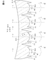
- FIG. 2 is an enlarged sectional view of FIG.
- FIG. 2 is an enlarged cross-sectional view taken along the line VII-VII of FIG.
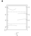
- It is a schematic diagram for demonstrating the illumination example of the image formation panel of FIG.
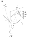
- the virtual image display device of the first embodiment is configured to be mounted on the vehicle 1 and is housed in the instrument panel 2 of the vehicle 1 as a head-up display (hereinafter referred to as HUD). It is 100.
- the vehicle 1 is broadly understood to include, for example, various vehicles such as automobiles, railroad vehicles, aircraft, ships, and non-moving game housings.
- the vehicle 1 of the present embodiment is a four-wheeled vehicle.
- the front, rear, up, down, left, and right directions of the HUD 100 are defined with reference to the vehicle 1 on the horizontal plane.
- the HUD100 projects the display light of the image toward the windshield 3 of the vehicle 1.
- the display light reflected by the windshield 3 reaches the visual recognition area EB set in the interior of the vehicle 1.
- the occupant whose eye point EP is located in the visible area EB in the interior of the vehicle 1 perceives the display light that has reached the visible area EB as a virtual image VRI.
- the HUD 100 causes the visual viewer 4 to recognize various information by displaying the virtual image VRI that can be visually recognized by the visual viewer (hereinafter, simply referred to as the visual viewer) 4 who is the occupant of the vehicle 1 in the visual recognition area EB.
- Various information displayed as a virtual image VRI by the HUD 100 include, for example, information indicating the state of the vehicle 1 such as vehicle speed and remaining fuel amount, visibility assist information, road information, navigation information, and the like.
- the viewing area EB is a spatial area that can be visually recognized by the viewer 4 when the virtual image VRI displayed by the HUD 100 satisfies a predetermined specification (for example, the entire virtual image VRI has a predetermined brightness or higher). Also called a box.
- the visible area EB is typically set so as to overlap the irips set in the vehicle 1.
- the eye lip is set in a virtual ellipsoid shape based on an eye range that statistically represents the spatial distribution of the eye point EP in the viewer 4.
- the windshield 3 is a translucent member formed in the shape of a translucent plate by, for example, glass or synthetic resin.
- the windshield 3 is located above the instrument panel 2 and divides the interior and exterior of the vehicle 1.
- the windshield 3 is inclined so as to be separated from the instrument panel 2 from the front to the rear.
- the rear surface of the windshield 3 on the indoor side has a reflective surface 3a on which display light is projected and reflected from the HUD 100, which is formed into a smooth concave surface or a flat surface.
- the windshield 3 may be configured to utilize diffracted reflection with interference fringes instead of surface reflection by providing a reflective holographic optical element. Further, instead of the windshield 3, a combiner as a translucent member may be installed in the interior of the vehicle 1, so that the combiner may be provided with the reflecting surface 3a.
- the HUD 100 includes a light guide unit 10, an image forming unit 20, a condensing unit 30, and a lighting unit 40.
- the light guide unit 10 constitutes an optical path P from the image forming unit 20 to the windshield 3.
- the light guide unit 10 guides the display light projected from the image forming unit 20 toward the windshield 3. It is preferable that the light guide unit 10 has a magnifying action of magnifying the image formed by the image forming unit 20 to a predetermined optical magnification to the virtual image VRI visually recognized by the viewer 4. This is because the light guide unit 10 can be miniaturized by the expanding action.
- the light guide unit 10 having such a function includes at least one optical member 11.
- the light guide unit 10 is configured by combining a plane mirror (or curved mirror) 11a and a concave mirror 11b as an optical member 11 one by one.
- the concave mirror 11b gives the above-mentioned magnifying action.
- the light guide unit 10 may be configured by combining a convex mirror and a concave mirror as the optical member 11 one by one, or may be configured by one concave mirror as the optical member 11. good.
- the optical member 11 constituting such a light guide unit 10 may be either a fixed type or a movable type.
- the image forming unit 20 forms an image that can be imaged as a virtual image VRI outside the vehicle 1, and emits the display light of the formed image toward the light guide unit 10. As shown in FIGS. 1 and 2, the image forming unit 20 includes an image display panel 21 and a diffusion panel 22.
- the image display panel 21 is formed in a plate shape as a whole.
- the image display panel 21 is a transmissive TFT liquid crystal panel using a thin film transistor.
- the image display panel 21 is an active matrix type having a plurality of liquid crystal pixels arranged two-dimensionally. Illumination light from the illumination unit 40 is incident on the incident surface 210, which is one side of the image display panel 21, through the condensing unit 30. From the emission surface 211 on the opposite side of the image display panel 21, the display light of the image is emitted toward the light guide unit 10 on the optical path P.
- the image display panel 21 displays and forms an image that serves as the display light.
- each substituent has a transmission axis and a blocking axis orthogonal to each other along both sides 210 and 211 of the image display panel 21.
- Each substituent transmits the polarized light at the azimuth angle of the transmission axis and absorbs the polarized light at the azimuth angle of the blocking axis.
- the liquid crystal layer is configured to be able to adjust the polarization of the illumination light transmitted according to the applied voltage of each liquid crystal pixel.
- the ratio of light transmitted through the polarizing element on the emission side, that is, the transmittance is adjusted for each liquid crystal pixel, so that an image is formed.
- a color filter can be provided on each liquid crystal pixel to form a color image.
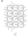
- a plurality of pixel regions 212 are set in the image display panel 21 so as to be arranged in two dimensions in the Xa direction and the Ya direction orthogonal to each other.
- the number of pixel regions 212 in the Xa direction may be small, large, or the same as the number of pixel regions 212 in the Ya direction, but is large in the first embodiment shown in FIG.
- the configuration is adopted.
- Each pixel region 212 is defined as a rectangular image forming region in which a predetermined number of liquid crystal pixels are two-dimensionally arranged in the Xa direction and the Ya direction.
- the diffusion panel 22 is formed as a whole from a hard transparent material such as glass or resin into a plate shape or a thin film shape.
- the diffusion panel 22 is arranged substantially parallel to the incident surface 210 of the image display panel 21.
- the diffusion panel 22 exerts a diffusion effect on the illumination light incident on the image display panel 21.
- the diffusion panel 22 may be integrally configured with the image display panel 21 by giving minute irregularities to the incident surface 210 of the image display panel 21.
- the light collecting unit 30 collects the illumination light from the lighting unit 40 toward the image forming unit 20.
- the light collecting unit 30 is mainly composed of a lens array 31.
- the lens array 31 is formed in a plate shape as a whole from a hard transparent material such as glass or resin.
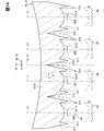
- the lens array 31 is a TIR lens array. As shown in FIGS. As a result, the structure is simplified and the cost is reduced.
- a plurality of individual incident surfaces 310 are formed side by side in two dimensions in the Xb direction and the Yb direction orthogonal to each other.
- the number of individual incident surfaces 310 in the Xb direction coincides with the number of pixel regions 212 in the Xa direction.
- the number of individual incident surfaces 310 in the Yb direction coincides with the number of pixel regions 212 in the Ya direction.
- each individual incident surface 310 is arranged in one of the pixel regions 212 in a 1: 1 manner. That is, the individual incident surface 310 is individually provided for each pixel region 212.
- Each individual incident surface 310 is provided with an optical axis Li that is substantially orthogonal to the Xb direction and the Yb direction. Each individual incident surface 310 exhibits a curved convex surface shape with the respective optical axis Li as the axis of symmetry in an arbitrary direction including the Xb direction and the Yb direction. Illumination light from the illumination unit 40 is incident on each individual incident surface 310. Each individual incident surface 310 collects the illumination light incident at the respective arrangement points toward the common emission surface 313 in the respective angular space ⁇ .
- the angle space ⁇ is defined by the angle formed by the light beam incident on the edge of the individual incident surface 310 from the outer edge of the light source unit 402, which will be described later, and refracted, and the optical axis Li.
- the angular space ⁇ of each individual incident surface 310 defined in this way is set so as to guide the illumination light into the corresponding pixel region 212.
- each individual transmission surface 311 is formed so as to be two-dimensionally arranged in the same number as the individual incident surfaces 310 in the Xb direction and the Yb direction.
- each individual transmission surface 311 is arranged in a 1: 1 correspondence with any one of the pixel regions 212 and any of the individual incident surfaces 310. That is, the individual transmission surface 311 is individually provided for each pixel region 212 and each individual incident surface 310.
- Each individual transmission surface 311 exhibits a tapered surface shape having a large diameter toward the illumination unit 40 side with the respective optical axis Li as the axis of symmetry in an arbitrary direction including the Xb direction and the Yb direction.
- Each individual transmission surface 311 forms a discontinuity portion in which the surface shape changes discontinuously at the boundary with the outer peripheral edge of the corresponding individual incident surface 310. Such a discontinuity becomes a discontinuity 314 between each individual incident surface 310. Illumination light from the illumination unit 40 is incident on each individual transmission surface 311.
- the individual reflecting surfaces 312 are formed two-dimensionally side by side in the same number as the individual transmitting surfaces 311 in the Xb direction and the Yb direction. As a result, each individual reflecting surface 312 is arranged in a 1: 1 correspondence with any of the pixel regions 212, any of the individual incident surfaces 310, and any of the individual transmission surfaces 311. That is, the individual reflecting surface 312 is individually provided for each pixel region 212, each individual incident surface 310, and each individual transmission surface 311. Each individual reflecting surface 312 exhibits a tapered surface shape having a smaller diameter toward the lighting unit 40 side with the respective optical axis Li as the axis of symmetry in an arbitrary direction including the Xb direction and the Yb direction.
- Each individual reflective surface 312 forms a discontinuous portion in which the surface shape changes discontinuously at the boundary with the outer peripheral edge of the corresponding individual transmissive surface 311.
- Each individual reflecting surface 312 forms a discontinuous portion in which the surface shape changes discontinuously with the outer peripheral edge of the adjacent individual reflecting surface 312. These discontinuous portions also become discontinuous portions 314 between the individual incident surfaces 310.
- Each individual reflecting surface 312 directs the illumination light transmitted through the corresponding individual transmitting surface 311 toward the common emission surface 313, and substantially totally reflects it in the angular space ⁇ of the corresponding individual incident surface 310.
- the common injection surface 313 is commonly formed on each of the individual incident surfaces 310 on the image forming unit 20 side of the individual incident surface 310. That is, the common ejection surface 313 is commonly provided on each pixel region 212, each individual transmission surface 311 and each individual reflection surface 312.
- the common injection surface 313 exhibits a curved concave surface having an optical axis Lo substantially orthogonal to the Xb direction and the Yb direction as an axis of symmetry in an arbitrary direction including the Xb direction and the Yb direction.
- the optical axis Lo of the common injection surface 313 is set substantially parallel to or substantially overlapping with the optical axis Li of each individual incident surface 310.
- the common injection surface 313 with respect to the optical axis Li of the individual incident surface 310 arranged in the center in the Yb direction.
- the optical axes Lo of are substantially overlapped.
- the common ejection surface 313 transfers the illumination light condensed into the angle space ⁇ by each individual incident surface 310 and the illumination light reflected into the angle space ⁇ by each individual reflection surface 312 into each pixel region 212. Eject toward. At this time, the common ejection surface 313 collects the illumination light so as to go through each pixel region 212 into the visual recognition region EB.
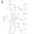
- the common injection surface 313 is constructed as a composite surface structure in which a wavefront diffusion surface shape Zw is synthesized with a concave base surface shape Zb as a structure represented by the following equation 1.
- the function representing the base surface shape Zb defined in the common ejection surface 313 may be given by, for example, the following Equation 2 in order to exert a light-collecting action in the visual recognition region EB. ..
- Equation 2 c is the curvature at any concave point.
- r is a radius (that is, a radius) from the optical axis Lo at an arbitrary concave point.
- k is a conic constant.
- Fi is a free-form surface coefficient.
- the diffusion surface shape Zw defined in the common injection surface 313 exhibits a wavefront shape in which waves travel from the virtual plane ⁇ including the optical axis Lo in the Xb direction toward the outside in the Yb direction.
- the common emission surface 313 diffuses the illumination light emitted toward each pixel region 212 into the visible region EB through each of the pixel regions 212 according to the wavefront-like diffusion surface shape Zw. Therefore, of Equation 1, the function representing the diffusion surface shape Zw in order to exert the diffusion effect in the visual recognition region EB may be given by, for example, the following Equation 3 that defines the one-dimensional plane wave surface.
- Ay is the maximum wavefront amplitude in the Yb direction.
- Yw is the distance between the virtual plane ⁇ and the Yb direction at an arbitrary point on the wavefront.
- ⁇ y is a wavefront wavelength in the Yb direction.
- the lighting unit 40 shown in FIGS. 1 and 2 emits illumination light that illuminates the image forming unit 20 through the condensing unit 30.
- the lighting unit 40 has a plurality of light source units 402 arranged two-dimensionally in the Xc direction and the Yc direction orthogonal to each other.
- the number of light source units 402 in the Xc direction coincides with the number of pixel regions 212 in the Xa direction and the number of individual incident surfaces 310 in the Xb direction.
- the number of light source units 402 in the Yc direction coincides with the number of pixel regions 212 in the Ya direction and the number of individual incident surfaces 310 in the Yb direction.
- each light source unit 402 is arranged in a 1: 1 correspondence with any of the pixel regions 212, any of the individual incident surfaces 310, and any of the individual transmission surfaces 311. That is, the individual reflecting surface 312 is individually provided for each pixel region 212, each individual incident surface 310, and each individual transmission surface 311.
- Each light source unit 402 is composed of a light source element that independently emits white illumination light.
- the light source element of each light source unit 402 is an LED bare chip using, for example, YAG or KSF.
- the light source element of each light source unit 402 can individually set the illuminance of the illumination light by variably adjusting the emission intensity.
- the light source element of each light source unit 402 is arranged on the optical axis Li of the corresponding individual incident surface 310.
- the light source element of each light source unit 402 is arranged closer to the light collecting unit 30 than the focal length of the corresponding surface 310 in the direction along the optical axis Li of the corresponding individual incident surface 310.
- each light source unit 402 emits illumination light that is individually incident on each individual incident surface 310.
- the intensity peak direction at which the light emission intensity of the light source element is maximized is set substantially parallel along the common optical axis Li of the corresponding individual incident surface 310 and the individual transmission surface 311.
- the Xc direction in which the lighting units 40 are lined up is defined to be substantially parallel along the Xb direction in which the individual incident surface 310 and the individual transmission surface 311 are lined up, and is defined to be inclined from the Xa direction in which the pixel regions 212 are lined up. Will be done.
- the Yc direction in which the illumination units 40 are lined up is defined to be substantially parallel along the Ya direction in which the pixel regions 212 are lined up and the Yb direction in which the individual incident surface 310 and the individual transmission surface 311 are lined up.
- the pixel region 212 corresponding to the light source unit 402 in which the light source element emits light at the maximum intensity is transmitted and illuminated by white light at the maximum illuminance.
- the pixel region 212 corresponding to the light source unit 402 in which the light source element emits light at a light intensity lower than the maximum intensity is transmitted and illuminated by white light at a light intensity lower than the maximum illuminance.
- the pixel area 212 corresponding to the light source unit 402 in which the light source element is turned off is a substantially non-display area that is not transmitted and illuminated.
- the number of elements 212, 310, 402 arranged in the Xa, Xb, Xc directions orthogonal to the optical axes Li, Lo is the element 212, in the Ya, Yb, Yc directions orthogonal to the optical axes Li, Lo. It is larger than the number of 310 and 402 lined up.
- the Xa, Xb, and Xc directions are associated with the left-right direction Dh of the virtual image VRI
- the Ya, Yb, and Yc directions are associated with the vertical direction Dv of the virtual image VRI.
- the size of the visual recognition area EB corresponding to the horizontal direction Dh of the virtual image VRI in the horizontal direction is the vertical direction of the visual recognition area EB corresponding to the vertical direction Dv of the virtual image VRI (FIG. 1). It is larger than the size in 1) in the vertical direction of the paper surface. Therefore, it is possible to effectively utilize the horizontally long windshield 3 in the vehicle 1 to provide a virtual image VRI display with improved visibility in the horizontally long viewing area EB, as described later.
- the image forming unit 20 includes a plurality of individual incident surfaces 310 that condense the incident illumination light into the respective angle space ⁇ at the arrangement locations arranged in the orthogonal direction of the optical axis Ai. It is provided individually for each of the plurality of pixel areas 212 in the above. Therefore, in the condensing unit 30, a common emission surface 313 that emits illumination light from each individual incident surface 310 and condenses it in the viewing area EB is provided in common in each pixel area 212 to display the illumination light in the viewing area. It is formed in a wavy shape that diffuses into the EB.
- the illumination light incident on the discontinuous portion 314 whose surface shape changes discontinuously between the individual incident surfaces 310 and the illumination light incident on each individual incident surface 310 are from within each angle space ⁇ .
- the light is condensed into the visible area EB in a mixed state due to the diffusion on the common injection surface 313.
- sharply shining edge light due to the discontinuous portion 314 between the individual incident surfaces 310 is less likely to occur. Therefore, it is possible to improve the illumination quality and improve the visibility of the virtual image VRI.
- the common injection surface 313 according to the first embodiment is formed in a wavefront shape in which waves travel in the Yb direction as an orthogonal direction.
- the apparent spread of the illumination light can be promoted by the diffusing action in the Yb direction in which the individual incident surfaces 310 are lined up. Therefore, it is possible to effectively suppress the edge light generated by the discontinuous portion 314 between the individual incident surfaces 310 and improve the visibility of the virtual image VRI.
- the Yb direction as the orthogonal direction in which the wave travels on the wave-shaped common injection surface 313 not only corresponds to the direction in which the individual incident surfaces 310 are lined up, but also in the vertical direction Dv of the virtual image VRI. handle.
- the left-right direction Dh of the virtual image VRI in which the eyeball of the viewer 4 who visually recognizes the virtual image VRI is easy to move
- the vertical direction Dv of the virtual image VRI in which the eyeball is difficult to move the brightness fluctuation of the display light in the visual recognition area EB is changed. It is unlikely to occur in the first place. Therefore, in combination with the suppression of edge light, it is possible to improve the visibility of the virtual image VRI.
- a light source unit 302 that emits illumination light incident on each individual incident surface 310 is individually provided for each of the surfaces 310.
- the illumination light incident on the corresponding individual incident surface 310 from each light source unit 402 and being diffused by the common ejection surface 313 apparently spreads to the pixel region 212 corresponding to the angle space ⁇ . Incident. Therefore, it is possible to suppress the incident of the edge light caused by the discontinuous portion 314 between the individual incident surfaces 310 for each pixel region 212 and improve the visibility of the virtual image VRI.
- the second embodiment is a modification of the first embodiment.
- the common injection surface 2313 of the second embodiment is constructed in a composite composite surface structure having a diffusion surface shape Zw different from that of the first embodiment with respect to the virtual base surface shape Zb similar to that of the first embodiment. There is.
- the diffusion surface shape Zw defined in the common injection surface 2313 exhibits a wavefront shape in which waves travel from the optical axis Li toward the outside at least in the Xc direction and the Yb direction.
- the function representing the diffusion surface shape Zw defined in the common injection surface 2313 may be given by, for example, the following number 4 defining a two-dimensional plane wave surface in order to exert a diffusion effect in the visual recognition region EB.
- Ax and Ay are the maximum wavefront amplitudes in the Xb and Yb directions, respectively.
- Xw is the separation distance in the Xb direction from the virtual plane ⁇ at an arbitrary point on the wavefront.
- the virtual plane ⁇ is defined as a plane including the optical axis Lo and extending in the Yb direction, orthogonal to the virtual plane ⁇ .
- Yw is the distance from the virtual plane ⁇ at an arbitrary point on the wavefront in the Yb direction.
- ⁇ x and ⁇ y are wavefront wavelengths in the Xb and Yb directions, respectively.
- Equation 5 The function representing the diffusion surface shape Zw defined in the common injection surface 2313 may be given, for example, by the following equation 5 defining the non-attenuated spherical wavefront.
- A is the maximum wavefront amplitude in an arbitrary direction around the optical axis Lo including the Xb and Yb directions.
- Xw and Yw are distances from the virtual planes ⁇ and ⁇ at arbitrary points on the wavefront in the Xb and Yb directions, respectively.
- Equation 5 ⁇ is a wavefront wavelength in an arbitrary direction around the optical axis Lo including the Xb and Yb directions.
- Equation 6 A is the maximum wavefront amplitude in an arbitrary direction around the optical axis Lo including the Xb and Yb directions.
- Xw and Yw are distances from the virtual planes ⁇ and ⁇ at arbitrary points on the wavefront in the Xb and Yb directions, respectively.
- ⁇ is a wavefront wavelength in an arbitrary direction around the optical axis Lo including the Xb and Yb directions.
- the function representing the diffusion surface shape Zw defined in the common injection surface 2313 may be given, for example, by the following numbers 7-9 defining the sinc wavefront.
- Ax and Ay are the maximum wavefront amplitudes in the Xb and Yb directions, respectively.
- Xw and Yw are distances from the virtual planes ⁇ and ⁇ at arbitrary points on the wavefront in the Xb and Yb directions, respectively.
- ⁇ x and ⁇ y are wavefront wavelengths in the Xb and Yb directions, respectively.
- the function representing the diffusion surface shape Zw defined in the common injection surface 2313 may be given by, for example, the following number 10 defining a synthetic two-dimensional plane wave surface.
- j is an integer from 1 to N, or a suffix represented by the integer, where N is the composite number of the wavefront.
- Axj and Ayj are the maximum wavefront amplitudes in the Xb and Yb directions, respectively.
- Xw and Yw are distances from the virtual planes ⁇ and ⁇ at arbitrary points on the wavefront in the Xb and Yb directions, respectively.
- ⁇ x and ⁇ y are wavefront wavelengths in the Xb and Yb directions, respectively.
- the maximum amplitudes Ax and Axj in the Xb direction are smaller, larger, or the same as those of the maximum amplitudes Ay and Ayj in the Yb direction. It may be either.
- the maximum amplitudes Ax and Axj are different from the maximum amplitudes Ay and Ayj, an anisotropic diffusion action is given to the illumination light.
- the maximum amplitudes Ax and Axj in the Xb direction corresponding to the left-right direction Dh of the virtual image VRI are larger than the maximum amplitudes Ay and Ayj in the Yb direction corresponding to the vertical direction Dv of the virtual image VRI. It should be set. As a result, in the second embodiment, it is possible to provide a highly visible virtual image VRI by the display light in which the illumination light is diffused with high efficiency toward the horizontally long viewing area EB.
- the common injection surface 2313 according to the second embodiment is formed in a wavefront shape in which waves travel in at least the Yb and Xb directions, which are a pair of orthogonal directions orthogonal to each other.
- the apparent spread of the illumination light can be promoted by the diffusion action in the Yb and Xb directions in which the individual incident surfaces 310 are lined up. Therefore, it is possible to suppress the incident of the edge light caused by the discontinuous portion 314 between the individual incident surfaces 310 for each pixel region 212 and improve the visibility of the virtual image VRI.
- the third embodiment is a modification of the first embodiment.
- the lens array 3031 of the third embodiment is a meniscus lens array.
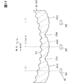
- the lens array 3031 is not provided with the plurality of individual transmission surfaces 311 and the plurality of individual reflection surfaces 312, and adopts a lens surface structure mainly composed of the plurality of individual incident surfaces 310 and the common ejection surface 313.
- each individual incident surface 310 forms a discontinuous portion in which the surface shape changes discontinuously with the outer peripheral edge of the adjacent individual incident surface 310. That is, these discontinuous portions become discontinuous portions 3314 between the individual incident surfaces 310.
- the edge light that shines sharply due to the discontinuous portion 3314 between the individual incident surfaces 310 is less likely to be generated by the same principle as that of the first embodiment, so that the illumination quality is improved. It is possible to improve the visibility of the virtual image VRI.
- the fourth embodiment is a modification of the first embodiment.
- the common injection surface 4313 of the fourth embodiment is constructed in a concave structure mainly composed of the base surface shape Zb similar to that of the first embodiment, in which the diffusion surface shape Zw is not synthesized.
- the common emission surface 4313 collects the illumination light to be emitted so as to pass through each pixel region 212 and toward the inside of the visual recognition region EB.
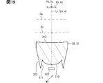
- each individual incident surface 4310 of the fourth embodiment is a composite surface in which a wavefront diffusion surface shape Zw is synthesized with a convex base surface shape Zb as a structure represented by the following equation 11. It is built in the structure.
- a discontinuous portion 314 is formed between the individual incident surfaces 4310 as in the first embodiment.
- the function representing the base surface shape Zb defined for each individual incident surface 4310 exerts a condensing action in the angular space ⁇ , for example, the same number 2 as in the first embodiment. May be given by.
- c is the curvature at an arbitrary point on the convex surface.
- r is a radius (that is, a radius) from the optical axis Li at an arbitrary point on the convex surface.
- the diffusion surface shape Zw defined on each individual incident surface 4310 presents a wavefront shape in which waves travel outward in the Yb direction from the virtual plane ⁇ including the optical axis Li and spreading in the Xb direction.
- Each individual incident surface 4310 diffuses the illumination light emitted from the common emission surface 4313 toward each pixel region 212 into each angle space ⁇ according to the wavefront-like diffusion surface shape Zw. Therefore, of the number 11, the function representing the diffusion surface shape Zw in order to exert the diffusion action in the angle space ⁇ is given by the number 3 similar to that of the first embodiment.
- each individual reflecting surface 312 of the fourth embodiment has a composite surface structure in which a wavefront diffusion surface shape Zw is synthesized with a tapered surface base surface shape Zb according to the individual incident surface 4310. It may be constructed. However, it is preferable that each individual transmission surface 311 of the fourth embodiment is formed in the same tapered surface shape as that of the first embodiment.
- a common ejection surface 4313 that emits illumination light and condenses it in the visual recognition region EB is commonly provided in a plurality of pixel regions 212 in the image forming unit 20. Therefore, the condensing unit 30 further condenses the incident illumination light into the respective angular space ⁇ at the arrangement locations arranged in the Yb direction as the orthogonal direction of the optical axis Li corresponding to each pixel region 212 individually.
- the plurality of individual incident surfaces 4310 are formed in a wavy shape that diffuses the illumination light into the angular space ⁇ .
- the illumination light incident on the discontinuous portion 314 whose surface shape changes discontinuously between the individual incident surfaces 4310 is incident on each individual incident surface 4310 and diffused in the angular space ⁇ . After mixing with, the light is focused in the visible area EB. As a result, sharply shining edge light due to the discontinuous portion 314 between the individual incident surfaces 4310 is less likely to occur in the visible region EB. Therefore, it is possible to improve the illumination quality and improve the visibility of the virtual image VRI.
- Each individual incident surface 4310 according to the fourth embodiment is formed in a wavefront shape in which waves travel in the Yb direction as an orthogonal direction.
- the apparent spread of the illumination light can be promoted by the diffusing action in the Yb direction in which the surfaces 4310 are lined up. Therefore, it is possible to effectively suppress the edge light generated by the discontinuous portion 314 between the individual incident surfaces 4310 and improve the visibility of the virtual image VRI.
- the Yb direction as the orthogonal direction in which the wave travels on each of the wave-shaped individual incident surfaces 4310 not only corresponds to the direction in which the surfaces 4310 are lined up, but also in the vertical direction Dv of the virtual image VRI. handle.
- the brightness of the display light in the visual area EB fluctuates in the vertical direction Dv of the virtual image VRI in which the eyeball is difficult to move, as opposed to the left-right direction Dh of the virtual image VRI in which the eyeball of the viewer 4 who visually recognizes the virtual image VRI is easy to move.
- the light source unit 302 that emits the illumination light incident on each individual incident surface 4310 is individually provided for each of the surface 310. Therefore, as in the first embodiment, it is possible to suppress the incident of the edge light caused by the discontinuous portion 314 between the individual incident surfaces 310 for each pixel region 212 and improve the visibility of the virtual image VRI. ..
- the fifth embodiment is a modification of the fourth embodiment to which the second embodiment is applied.
- Each individual incident surface 5310 of the fifth embodiment is constructed in a composite composite surface structure having a diffusion surface shape Zw different from that of the fourth embodiment with respect to the base surface shape Zb similar to the fourth embodiment. There is.
- a discontinuous portion 314 is formed between the individual incident surfaces 5310 as in the first embodiment.
- the diffusion surface shape Zw defined on each of the individual incident surfaces 5310 exhibits a wavefront shape in which waves travel from the optical axis Li toward the outside at least in the Xc direction and the Yb direction.
- the function representing the diffusion surface shape Zw defined in each individual incident surface 5310 is given by any one of the number 4, number 5, number 6, number 7-9 and number 10 as in the second embodiment, for example. May be good.
- the virtual plane ⁇ with respect to the number 4, number 5, number 6, number 7 to 9, and number 10 is defined orthogonal to the virtual plane ⁇ as a plane including the optical axis Li and extending in the Yb direction.
- ⁇ is a wavefront wavelength in an arbitrary direction around the optical axis Li including the Xb and Yb directions.
- the maximum amplitudes Ax and Axj in the Xb direction corresponding to the left-right direction Dh of the virtual image VRI are the maximum amplitudes in the Yb direction corresponding to the vertical direction Dv of the virtual image VRI. It is better to set it larger than Ay and Ayj. As a result, even in the fifth embodiment, it is possible to provide a highly visible virtual image VRI by the display light in which the illumination light is diffused with high efficiency toward the horizontally long viewing area EB.
- each individual incident surface 5310 according to the fifth embodiment is formed in a wavefront shape in which waves travel in at least the Yb and Xb directions, which are a pair of orthogonal directions orthogonal to each other.
- the apparent spread of the illumination light can be promoted by the diffusion action in the Yb and Xb directions in which the individual incident surfaces 5310 are lined up. Therefore, it is possible to suppress the incident of the edge light caused by the discontinuous portion 314 between the individual incident surfaces 5310 for each pixel region 212 and improve the visibility of the virtual image VRI.
- the sixth embodiment is a modification in which the common injection surface 313 of the first embodiment and each individual incident surface 4310 of the fourth embodiment are combined.
- the illumination light incident on the discontinuous portion 314 whose surface shape changes discontinuously between the individual incident surfaces 4310 and the illumination light incident on each individual incident surface 4310 in the angular space ⁇ .
- the illumination light diffused in the light is condensed into the visual recognition area EB in a state of being mixed together with the diffusion on the common injection surface 313.
- sharply shining edge light due to the discontinuous portion 314 between the individual incident surfaces 4310 is less likely to occur in the visible region EB. Therefore, it is possible to improve the illumination quality and improve the visibility of the virtual image VRI.
- the seventh embodiment is a modification of the fourth embodiment.
- the lens array 7031 of the seventh embodiment is a meniscus lens array.
- the lens array 7031 is not provided with a plurality of individual transmission surfaces 311 and a plurality of individual reflection surfaces 312, and adopts a lens surface structure mainly composed of a plurality of individual incident surfaces 4310 and a common ejection surface 4313.
- each individual incident surface 4310 forms a discontinuous portion in which the surface shape changes discontinuously with the outer peripheral edge of the adjacent individual incident surface 4310. That is, these discontinuous portions become discontinuous portions 7314 between the individual incident surfaces 4310.
- the edge light that shines sharply due to the discontinuous portion 7314 between the individual incident surfaces 4310 is less likely to be generated by the same principle as that of the fourth embodiment, so that the illumination quality is improved. It is possible to improve the visibility of the virtual image VRI.
- the eighth embodiment is a modified example in which the common injection surface 313 of the third embodiment and each individual incident surface 4310 of the seventh embodiment forming the discontinuous portion 7314 between them are combined. be.
- the illumination light incident on the discontinuous portion 7314 whose surface shape changes discontinuously between the individual incident surfaces 4310 and the illumination light incident on each individual incident surface 4310 within the angular space ⁇ .
- the illumination light diffused in the light is condensed into the visual recognition area EB in a state of being mixed together with the diffusion on the common injection surface 313.
- sharply shining edge light due to the discontinuous portion 7314 between the individual incident surfaces 4310 is less likely to occur in the visible region EB. Therefore, it is possible to improve the illumination quality and improve the visibility of the virtual image VRI.
- the image display panel 21 and the diffusion panel 22 are substantially perpendicular to the optical axes Li and Lo. It may be arranged in.
- the individual incident surfaces 310 and 4310 in the modified examples of the first, third, fourth and sixth to eighth embodiments are in the Xb direction. They may be lined up in one dimension in a row.
- the individual transmission surface 311 and the individual reflection surface 312 in the modified examples of the first, fourth, and sixth embodiments may be arranged one-dimensionally in a row in the Xb direction, respectively.
- the pixel regions 212 in the first, third, fourth, and sixth to eighth embodiments may be arranged in one dimension in a row in the Xa direction.
- the light source units 402 in the first, third, fourth, and sixth to eighth embodiments may be arranged one-dimensionally in a row in the Xc direction.
- the Xa direction and the Ya direction of the image forming unit 20 may be interchanged with each other.
- the Xb direction and the Yb direction of the light collecting unit 30 may be interchanged with each other.
- the Xc direction and the Yc direction of the lighting unit 40 may be interchanged with each other.
- the common injection surface 2313 of the second embodiment may be adopted.
- the common injection surface 2313 of the second embodiment and the individual incident surface 5310 of the fifth embodiment may be adopted.
- the individual incident surface 5310 of the fifth embodiment may be adopted.
Landscapes
- Engineering & Computer Science (AREA)
- Chemical & Material Sciences (AREA)
- Combustion & Propulsion (AREA)
- Transportation (AREA)
- Mechanical Engineering (AREA)
- Physics & Mathematics (AREA)
- General Physics & Mathematics (AREA)
- Optics & Photonics (AREA)
- Instrument Panels (AREA)
Applications Claiming Priority (2)
| Application Number | Priority Date | Filing Date | Title |
|---|---|---|---|
| JP2020206853A JP7354999B2 (ja) | 2020-12-14 | 2020-12-14 | 虚像表示装置 |
| JP2020-206853 | 2020-12-14 |
Publications (1)
| Publication Number | Publication Date |
|---|---|
| WO2022130823A1 true WO2022130823A1 (ja) | 2022-06-23 |
Family
ID=82057520
Family Applications (1)
| Application Number | Title | Priority Date | Filing Date |
|---|---|---|---|
| PCT/JP2021/040797 Ceased WO2022130823A1 (ja) | 2020-12-14 | 2021-11-05 | 虚像表示装置 |
Country Status (2)
| Country | Link |
|---|---|
| JP (1) | JP7354999B2 (https=) |
| WO (1) | WO2022130823A1 (https=) |
Cited By (3)
| Publication number | Priority date | Publication date | Assignee | Title |
|---|---|---|---|---|
| EP4451041A1 (en) * | 2023-04-18 | 2024-10-23 | Continental Automotive Technologies GmbH | Head-up display unit |
| US20250013040A1 (en) * | 2021-11-12 | 2025-01-09 | Koito Manufacturing Co., Ltd. | Image generation apparatus and head-up display |
| WO2025219152A1 (de) * | 2024-04-16 | 2025-10-23 | Carl Zeiss Jena Gmbh | Head-up-display eines luftfahrzeugs |
Citations (5)
| Publication number | Priority date | Publication date | Assignee | Title |
|---|---|---|---|---|
| US20070109400A1 (en) * | 2003-07-10 | 2007-05-17 | Ocuity Limited | Directional display apparatus |
| WO2007072600A1 (ja) * | 2005-12-20 | 2007-06-28 | Sharp Kabushiki Kaisha | 表示装置および液晶表示装置 |
| JP2014102311A (ja) * | 2012-11-19 | 2014-06-05 | Seiko Epson Corp | マイクロレンズアレイ基板、マイクロレンズアレイ基板の製造方法、電気光学装置、電子機器 |
| US20190369392A1 (en) * | 2018-05-30 | 2019-12-05 | Visteon Global Technologies, Inc. | Picture generation unit for head-up display |
| JP2020154202A (ja) * | 2019-03-22 | 2020-09-24 | 矢崎総業株式会社 | ヘッドアップディスプレイ装置 |
-
2020
- 2020-12-14 JP JP2020206853A patent/JP7354999B2/ja active Active
-
2021
- 2021-11-05 WO PCT/JP2021/040797 patent/WO2022130823A1/ja not_active Ceased
Patent Citations (5)
| Publication number | Priority date | Publication date | Assignee | Title |
|---|---|---|---|---|
| US20070109400A1 (en) * | 2003-07-10 | 2007-05-17 | Ocuity Limited | Directional display apparatus |
| WO2007072600A1 (ja) * | 2005-12-20 | 2007-06-28 | Sharp Kabushiki Kaisha | 表示装置および液晶表示装置 |
| JP2014102311A (ja) * | 2012-11-19 | 2014-06-05 | Seiko Epson Corp | マイクロレンズアレイ基板、マイクロレンズアレイ基板の製造方法、電気光学装置、電子機器 |
| US20190369392A1 (en) * | 2018-05-30 | 2019-12-05 | Visteon Global Technologies, Inc. | Picture generation unit for head-up display |
| JP2020154202A (ja) * | 2019-03-22 | 2020-09-24 | 矢崎総業株式会社 | ヘッドアップディスプレイ装置 |
Cited By (4)
| Publication number | Priority date | Publication date | Assignee | Title |
|---|---|---|---|---|
| US20250013040A1 (en) * | 2021-11-12 | 2025-01-09 | Koito Manufacturing Co., Ltd. | Image generation apparatus and head-up display |
| EP4451041A1 (en) * | 2023-04-18 | 2024-10-23 | Continental Automotive Technologies GmbH | Head-up display unit |
| WO2024218008A1 (en) | 2023-04-18 | 2024-10-24 | Continental Automotive Technologies GmbH | Head-up display unit |
| WO2025219152A1 (de) * | 2024-04-16 | 2025-10-23 | Carl Zeiss Jena Gmbh | Head-up-display eines luftfahrzeugs |
Also Published As
| Publication number | Publication date |
|---|---|
| JP7354999B2 (ja) | 2023-10-03 |
| JP2022094052A (ja) | 2022-06-24 |
Similar Documents
| Publication | Publication Date | Title |
|---|---|---|
| CN1132039C (zh) | 图象显示装置和包括这种装置的头戴显示器 | |
| JP6579212B2 (ja) | ヘッドアップディスプレイ装置 | |
| JP7195454B2 (ja) | 光源装置、それを利用した情報表示システムおよびヘッドアップディスプレイ装置 | |
| WO2022130823A1 (ja) | 虚像表示装置 | |
| US9891433B2 (en) | Virtual image generation device and head-up display | |
| JP7172840B2 (ja) | 虚像表示装置 | |
| CN115917399B (zh) | 虚拟图像显示装置 | |
| WO2017130481A1 (ja) | ヘッドアップディスプレイ装置及びその生産方法 | |
| JP6984619B2 (ja) | 虚像表示装置 | |
| JP7163804B2 (ja) | ヘッドアップディスプレイ用照明ユニット | |
| US20120249968A1 (en) | Autostereoscopic display | |
| JP7318597B2 (ja) | 虚像表示装置 | |
| EP4120001B1 (en) | Virtual image display device | |
| JP7314873B2 (ja) | 虚像表示装置 | |
| JPWO2014041690A1 (ja) | 光学素子及びヘッドアップディスプレイ | |
| WO2018173955A1 (ja) | 画像表示装置、虚像表示装置、移動体 | |
| WO2022019101A1 (ja) | ヘッドアップディスプレイ装置及びヘッドアップディスプレイ用拡散板 | |
| WO2017145558A1 (ja) | ヘッドアップディスプレイ装置 | |
| JP7342790B2 (ja) | 虚像表示装置 | |
| JP7839546B2 (ja) | ヘッドアップディスプレイ及び表示装置 | |
| CN120981758A (zh) | 在基于投影机的图像发生器中具有精确且低损耗反射的屏幕的用于车辆的平视显示器 |
Legal Events
| Date | Code | Title | Description |
|---|---|---|---|
| 121 | Ep: the epo has been informed by wipo that ep was designated in this application |
Ref document number: 21906187 Country of ref document: EP Kind code of ref document: A1 |
|
| NENP | Non-entry into the national phase |
Ref country code: DE |
|
| 122 | Ep: pct application non-entry in european phase |
Ref document number: 21906187 Country of ref document: EP Kind code of ref document: A1 |