WO2022124232A1 - 画像処理システム及び画像処理方法 - Google Patents
画像処理システム及び画像処理方法 Download PDFInfo
- Publication number
- WO2022124232A1 WO2022124232A1 PCT/JP2021/044535 JP2021044535W WO2022124232A1 WO 2022124232 A1 WO2022124232 A1 WO 2022124232A1 JP 2021044535 W JP2021044535 W JP 2021044535W WO 2022124232 A1 WO2022124232 A1 WO 2022124232A1
- Authority
- WO
- WIPO (PCT)
- Prior art keywords
- visual
- visual sensor
- sensor
- pattern
- visual pattern
- Prior art date
- Legal status (The legal status is an assumption and is not a legal conclusion. Google has not performed a legal analysis and makes no representation as to the accuracy of the status listed.)
- Ceased
Links
Images
Classifications
-
- B—PERFORMING OPERATIONS; TRANSPORTING
- B25—HAND TOOLS; PORTABLE POWER-DRIVEN TOOLS; MANIPULATORS
- B25J—MANIPULATORS; CHAMBERS PROVIDED WITH MANIPULATION DEVICES
- B25J9/00—Program-controlled manipulators
- B25J9/16—Program controls
- B25J9/1679—Program controls characterised by the tasks executed
- B25J9/1692—Calibration of manipulator
-
- H—ELECTRICITY
- H04—ELECTRIC COMMUNICATION TECHNIQUE
- H04N—PICTORIAL COMMUNICATION, e.g. TELEVISION
- H04N23/00—Cameras or camera modules comprising electronic image sensors; Control thereof
- H04N23/60—Control of cameras or camera modules
- H04N23/67—Focus control based on electronic image sensor signals
-
- G—PHYSICS
- G06—COMPUTING OR CALCULATING; COUNTING
- G06T—IMAGE DATA PROCESSING OR GENERATION, IN GENERAL
- G06T7/00—Image analysis
- G06T7/80—Analysis of captured images to determine intrinsic or extrinsic camera parameters, i.e. camera calibration
-
- H—ELECTRICITY
- H04—ELECTRIC COMMUNICATION TECHNIQUE
- H04N—PICTORIAL COMMUNICATION, e.g. TELEVISION
- H04N23/00—Cameras or camera modules comprising electronic image sensors; Control thereof
- H04N23/60—Control of cameras or camera modules
- H04N23/61—Control of cameras or camera modules based on recognised objects
-
- G—PHYSICS
- G05—CONTROLLING; REGULATING
- G05B—CONTROL OR REGULATING SYSTEMS IN GENERAL; FUNCTIONAL ELEMENTS OF SUCH SYSTEMS; MONITORING OR TESTING ARRANGEMENTS FOR SUCH SYSTEMS OR ELEMENTS
- G05B2219/00—Program-control systems
- G05B2219/30—Nc systems
- G05B2219/39—Robotics, robotics to robotics hand
- G05B2219/39045—Camera on end effector detects reference pattern
Definitions
- the present invention relates to an image processing system and an image processing method.
- Patent Document 5 states that "the image processing system SYS specifies the normal V for the set measurement point Wp of the work W according to the arrangement status of the specified work W, and the specified normal V and 2 The position and orientation of the two-dimensional camera 310 are changed so that the optical axis of the two-dimensional camera 310 coincides with the optical axis of the two-dimensional camera 310 (S1). By changing the distance between the 2D camera 310 and the measurement point Wp, the focus of the 2D camera 310 is adjusted to the measurement point Wp. "(Summary).
- Patent Document 5 describes a configuration in which focus adjustment is performed by adjusting a distance between a camera and a specific work, but in the configuration according to Patent Document 5, a process for designating the shape of the work and a structure of the work are described. Complex processing such as processing for specifying the arrangement state and processing for obtaining the normal of the work and settings for that are required. Further, since the work may have various shapes, it may not be possible to correctly acquire the arrangement information of the work, acquire the normal, and calculate the degree of focus.
- One aspect of the present disclosure is an industrial machine, a visual sensor, a visual pattern arranged at a detection target location, a visual pattern for specifying a relative positional relationship between the visual sensor and the visual pattern, and the above. Determined from an image in which the visual pattern is captured by a visual sensor, with an image processing unit that determines the relative positional relationship between the visual sensor and the visual pattern, and a state in which the visual pattern is reflected in the visual field of the visual sensor.
- the visual pattern is imaged by the visual sensor while changing the relative position between the visual sensor and the visual pattern in a predetermined direction with respect to the visual pattern based on the relative positional relationship.
- It is an image processing system including a focusing operation control unit for focusing the visual sensor on the visual pattern by obtaining the degree of focusing.
- the relative positional relationship between the visual sensor and the visual pattern is determined from an image captured by the visual sensor of the visual pattern arranged at the detection target location, and the visual pattern is displayed in the visual field of the visual sensor.
- the visual pattern is displayed by the visual sensor while changing the relative position between the visual sensor and the visual pattern in a predetermined direction with respect to the visual pattern based on the determined relative positional relationship.
- the visual sensor By arranging the visual pattern at the detection target location, the visual sensor can be automatically focused on the location where the visual pattern is arranged.
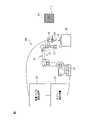
- FIG. 1 is a diagram showing a device configuration of a robot system 100 according to an embodiment.
- the robot system 100 includes an industrial robot (hereinafter referred to as a robot) 10 as an industrial machine, a robot control device 50 for controlling the robot 10, a visual sensor 70, and a visual sensor 70.
- a visual sensor control device 20 for controlling is provided.
- the robot system 100 is a system for recognizing the position of the work based on the captured image of the work captured by the visual sensor 70 and executing a predetermined work such as inspection, handling, and processing of the work.
- the robot 10 is a vertical articulated robot in the example of FIG. 1, but other types of robots may be used.
- the visual sensor control device 20 and the robot control device 50 are connected via a communication interface and can exchange various information.
- a tool 31 as an end effector is attached to the tip surface of the flange 11 at the tip of the arm of the robot 10.
- the tool 31 is, for example, a hand that grips a work.
- the robot 10 executes a predetermined work such as handling a work under the control of the robot control device 50.
- the visual sensor 70 is attached to a support portion of the tool 31 (that is, a predetermined movable portion of the robot 10).
- the visual sensor 70 is controlled by the visual sensor control device 20 to image an image-taking object such as a work.
- a general two-dimensional camera may be used, or a three-dimensional sensor such as a stereo camera may be used.
- the visual sensor 70 includes an image pickup sensor (CCD, CMOS, etc.) that receives a subject image and performs photoelectric conversion, and an optical lens that condenses the subject image on the image pickup sensor.
- the visual sensor 70 transmits the captured image data to the visual sensor control device 20.
- FIG. 1 shows an image M1 in which the visual sensor 70 in the state of FIG. 1 captured the calibration jig J.
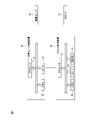
- FIG. 2 is a diagram showing a schematic configuration of the hardware of the visual sensor control device 20 and the robot control device 50.
- the visual sensor control device 20 has a memory (including ROM, RAM, non-volatile memory, etc.) 22 and an input / output interface 23 for communicating with an external device with respect to the processor 21. May have a configuration as a general computer connected via a bus.
- the robot control device 50 operates the processor 51 including a memory (including ROM, RAM, non-volatile memory, etc.) 52, an input / output interface 53 for communicating with an external device, and various operation switches.
- the unit 54 and the like may have a configuration as a general computer connected via a bus.
- a teaching device for teaching the robot 10 may be further connected to the robot control device 50.
- the visual sensor control device 20 and the robot control device 50 are configured as separate devices, but the visual sensor control device 20 and the robot control device 50 are configured as the same device. You can also.
- the function of the visual sensor control device 20 may be incorporated into the robot control device 50.
- the robot coordinate system C1 is set in the robot 10.
- the robot coordinate system C1 is a control coordinate system for controlling the operation of each movable element of the robot 10, and is fixed in a three-dimensional space.
- the origin of the robot coordinate system C1 is set at the center of the base portion of the robot 10, but the robot coordinate system C1 has a different position and posture. It may be set.
- a flange coordinate system C2 is set on the tip surface of the flange 11.
- the flange coordinate system C2 is a control coordinate system for controlling the position and orientation of the flange 11 in the robot coordinate system C1.
- the flange coordinate system C2 may be set to have a different position or orientation.
- the robot control device 50 sets the flange coordinate system C2 in the robot coordinate system C1, and the position and orientation represented by the set flange coordinate system C2.
- the servomotor of each joint portion of the robot 10 is controlled so that the flange 11 is arranged on the robot 10. In this way, the robot control device 50 can position the flange 11 (tool 31) at an arbitrary position and posture in the robot coordinate system C1.
- the sensor coordinate system C3 is set in the visual sensor 70.
- the sensor coordinate system C3 is a coordinate system that defines the coordinates of each pixel of the image data captured by the visual sensor 70, and its origin is arranged at the center of the light receiving surface (or optical lens) of the image sensor of the visual sensor 70.
- the x-axis and the y-axis are arranged parallel to the horizontal and vertical directions of the image sensor, and the z-axis coincides with the line of sight (optical axis) of the visual sensor 70 with respect to the visual sensor 70. Is set.
- the robot system 100 captures a visual pattern arranged at a detection target location by the visual sensor 70 for specifying a relative positional relationship between the visual sensor 70 and the visual pattern.
- the detection target portion by the visual sensor 70 is the upper surface of the table 60 on which the work is mounted, and the visual pattern is formed on the calibration jig J.
- the visual pattern may be a visually recognizable form such as a pattern using paint or an engraving (unevenness).
- the visual pattern may be directly formed at the detection target position (upper surface of the table 60).
- the term visual pattern includes patterns, marks, indicators, identification marks, symbols and various other visual indications.
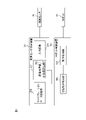
- FIG. 3 is a functional block diagram showing the functional configurations of the visual sensor control device 20 and the robot control device 50 when focusing on the function of the robot system 100 as an image processing system.
- the visual sensor control device 20 includes an image processing unit 202 that executes image processing on the input image 201 captured by the visual sensor 70, and a reference coordinate system (robot coordinate system C1) set in the robot 10.
- the calibration data storage unit 204 for storing the calibration data that determines the relative position of the visual sensor 70 (sensor coordinate system C3) with respect to the flange coordinate system C2) is provided.
- the image processing unit 202 has a function of detecting a work from an input image using, for example, a model pattern, and detecting the position and posture of the work, as a function for realizing handling of the work. Further, the image processing unit 202 according to the present embodiment includes an in-focus degree calculation unit 203 for calculating the in-focus degree of the object captured in the captured image.
- the calibration data storage unit 204 stores the calibration data of the visual sensor 70.
- the calibration data storage unit 204 is, for example, a non-volatile memory (EEPROM or the like).
- the calibration data of the visual sensor 70 includes internal parameters and external parameters of the visual sensor 70 (camera). Internal parameters include optical data such as lens strain and focal length.
- the external parameter is the position of the visual sensor 70 with respect to a predetermined reference position (for example, the position of the flange 11).
- the geometric transformation characteristics inside the camera and the geometric relationship between the three-dimensional space where the object exists and the two-dimensional image plane can be obtained, and further, the characteristics of the calibration jig J can be used for visual observation.
- the three-dimensional spatial positions of the visual sensor 70 and the calibration jig J can be uniquely determined. That is, the position / posture of the calibration jig can be obtained from the information of the calibration jig J in the captured image captured by the calibrated visual sensor 70 with respect to the position of the visual sensor 70.
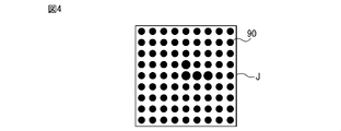
- FIG. 4 is a plan view of the calibration jig J.
- the calibration jig J is a variety of calibration jigs known in the art that can determine the position and orientation of the calibration jig based on the position of the visual sensor 70 from the image taken by the visual sensor 70. Can be used.
- the calibration jig J of FIG. 4 is a jig that can acquire information necessary for calibration of the visual sensor 70 by capturing a dot pattern arranged on a plane with the visual sensor 70 (1). )
- the grid point spacing of the dot pattern is known, (2) there are a certain number of grid points or more, and (3) it is possible to uniquely identify which grid point each grid point corresponds to. Meet.
- the calibration jig J is not limited to one in which features such as a predetermined dot pattern are arranged on a two-dimensional plane as shown in FIG. 4, and may be one in which features are arranged on a three-dimensional solid. It suffices as long as the three-dimensional position information including the position information in the height direction (arrow 91 direction in FIG. 1) in addition to the dimensional position information (X direction and Y direction) can be obtained. Further, the calibration jig J may be the same as or different from the one used when acquiring the calibration data of the visual sensor 70. In addition, in order to calculate the position and orientation of the dot pattern with respect to the position of the visual sensor 70 from the dot pattern captured by the visual sensor 70, the internal parameters of the calibration data described above are used.
- the calibration jig J having a dot pattern as shown in FIG. 4 is used as the object for obtaining the position and orientation of the object as seen from the image pickup device.
- Any type of object that can determine the position and orientation of the object as seen from the visual sensor 70) can be used.
- the calibration jig J is installed at a target location (that is, the upper surface of the table 60) where the visual sensor 70 is focused.
- the robot control device 50 includes an operation control unit 501 that controls the operation of the robot 10 according to an operation program. Further, the robot control device 50 according to the present embodiment controls to move the robot 10 to the in-focus position by moving the robot 10 based on the in-focus degree calculated by the in-focus degree calculation unit 203. An operation control unit 502 is provided.
- the processor (CPU) of the visual sensor control device 20 or the robot control device 50 executes various hardware stored in the memory. It may be realized by, or it may be realized by a configuration mainly composed of hardware such as ASIC (Application Specific Integrated Circuit).
- ASIC Application Specific Integrated Circuit
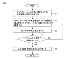
- FIG. 5 is a flowchart showing the flow of the focusing operation (image processing method) by the focusing operation control unit.
- the calibration data of the visual sensor 70 is stored in the calibration data storage unit 204 in advance.
- the focusing operation of FIG. 5 is executed under the control of the processor 51 of the robot control device 50.
- the focusing operation control unit 502 calculates and acquires the positional relationship between the calibration jig J and the visual sensor 70 based on the image captured by the calibration jig J by the visual sensor 70. In this case, the focusing operation control unit 502 uses the calibration data stored in the calibration data storage unit J.
- the focusing operation control unit 502 is located in the normal direction between the optical axis of the visual sensor 70 and the upper surface of the calibration jig J. Taking a picture of the calibration jig J while moving the visual sensor 70 so as to be parallel to the direction of the arrow 91 in FIG. 1 (step S2). At this time, the focusing operation control unit 502 causes the focusing degree calculation unit 203 to calculate the focusing degree of the image of the object (that is, the dot point of the calibration jig J) reflected in the image (step S3).
- the in-focus operation control unit 502 sets the in-focus degree calculated by the in-focus degree calculation unit 203 as a reference value (focusing) as a value when the in-focus degree of the dot point of the calibration jig J is the highest. By comparing with the degree reference value), it is determined whether or not the in-focus degree acquired in step S3 has the highest in-focus degree (step S4).
- the reference value (focusing degree reference value) used here may be stored in advance by the robot control device 50 (focusing operation control unit 502), or the focusing operation control unit 502 may have, for example, a predetermined movement range.
- the visual sensor 70 may be moved to set the highest focusing degree as the focusing degree reference value.
- the focusing operation control unit 502 When it is not determined that the focusing degree is the highest (S4: NO), the focusing operation control unit 502 continues the process of confirming the focusing degree (step S2-S4) while moving the visual sensor 70. When it is determined that the focusing degree is the highest (S4: YES), the focusing operation control unit 502 determines the position (focusing position) of the visual sensor 70 when the focusing degree is the highest. It is recorded as an imaging position (step S5).
- the in-focus degree calculation unit 203 can adopt various calculation methods known in the art such as a phase difference detection method and a contrast detection method as the in-focus degree calculation method.
- the in-focus degree calculation unit 203 detects contrast when it is determined that the reliability of the in-focus degree detected by the phase difference detection method is low, as described in Japanese Patent Application Laid-Open No. 2013-29803.
- a method may be used in which a pixel range using the phase difference detection method is selected based on the detection result by the method, and the in-focus degree is calculated by the phase difference detection method using the signal of the selected pixel range. ..
- the in-focus degree calculation unit 203 can acquire the data used for the in-focus degree calculation from the functional element for the in-focus calculation in the visual sensor 70.
- the predetermined operating range for moving the visual sensor 70 in the processes of steps S2 to S4 may be determined based on the adjustment range of the focal length of the camera.
- the robot 10 may be controlled to move the visual sensor 70 within a shooting distance determined based on the focus adjustment range of the visual sensor 70 in the focus adjustment ring. Since the positional relationship between the visual sensor 70 and the calibration jig J is known in step S1, such movement control of the visual sensor 70 is possible.
- the imaging position recorded in step S5 is used as an imaging position for positioning the visual sensor 70 when performing a predetermined work such as an appearance inspection of the work placed on the upper surface of the table 60.
- a predetermined work such as an appearance inspection of the work placed on the upper surface of the table 60.
- the visual sensor 70 can be automatically positioned at a position in focus with respect to the position where the calibration jig J is installed. That is, the focus adjustment of the visual sensor 70 can be automatically and efficiently performed.
- the robot control device 50 and the visual sensor control device 20 are various calibration methods known in the art (eg, for example).
- the calibration data may be acquired by using the above-mentioned Patent Document 2-5).
- the calibration jig J is used in the focusing control operation of FIG. 5, the calibration jig J is used in place when performing the focusing control operation of FIG. It is also easy to calibrate with. Since the method of calibrating the camera itself is a well-known technique, the explanation is omitted, but for example, "An Efficient and Accurate Camera Calibration Technique for 3D Machine Vision" by Roger Y. Tsai (CVPR, pp.364-374, It is described in detail in 1986 (IEEE). As a specific means, a jig such as the calibration jig J shown in FIG. 4 (a dot pattern plate in which dots are formed in a known geometric arrangement) is orthogonal to the optical axis of the camera, and the known 2 is used. The camera can be calibrated by measuring at the position of the point.
- a jig such as the calibration jig J shown in FIG. 4 (a dot pattern plate in which dots are formed in a known geometric arrangement) is orthogonal
- the focusing operation control unit 502 may be further configured to control such a function.
- the optical axis of the visual sensor 70 is determined with respect to the calibration jig J in the above-mentioned focusing operation. (For example, in the normal direction).
- the posture data of the visual sensor 70 in the reference coordinate system is acquired based on the image data of the index ID captured by the visual sensor 70.
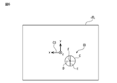
- FIG. 6 shows an example of the index ID.
- the index ID is provided at the detection target position (upper surface of the table 60), and is composed of a circular line C and two straight lines D and E orthogonal to each other.
- the index ID may be in a visually recognizable form, such as a pattern using paint or a marking (unevenness) formed on the upper surface of the table 60.
- the robot control device 50 obtains the posture of the sensor coordinate system C3 with reference to the reference coordinate system set in the robot 10 by the following procedure.
- (A1) With the visual sensor 70 arranged at the initial position PS 0 and the initial posture OR 0 so that the index ID is in the field of view of the visual sensor 70 by the robot control device 50, the index ID is imaged and the image of the index ID is imaged.
- Data JD 0 is acquired. It is assumed that an image (JD n ) as shown in FIG. 6 is acquired.
- the image processing unit 202 acquires the coordinates (x n , y n ) of the intersection F from the image of the index ID reflected in the image JD n as the position of the index ID, and the area of the circle C is the size IS of the index ID. Obtained as n (unit: pixel).
- the image processing unit 202 includes the size RS (unit: mm) of the index ID in the real space, the focal length FD of the optical lens of the visual sensor 70, and the size SS (unit: mm / pixel) of the image sensor. ).
- the image processing unit 202 acquires a vector (Xn, Yn, Zn) using the acquired coordinates (xn, yn), size ISn, size RS, focal length FD, and size SS.
- This vector (Xn, Yn, Zn) is a vector from the visual sensor 70 (that is, the origin of the sensor coordinate system C3) when the image data JDn is imaged to the index ID (specifically, the intersection F). , Data indicating the relative position of the index ID with respect to the visual sensor 70 (or the coordinates of the sensor coordinate system C3).
- the image processing unit 202 captures an image of the index ID at the position PS 1 and the posture OR 0 in which the visual sensor 70 is translated by a predetermined distance ⁇ x in the x-axis direction of the flange coordinate system from the initial position. From JD 1 , the vector from the visual sensor 70 when the image data JD 1 is imaged to the index ID is acquired. (A5) Similarly, the image processing unit 202 captures an image of the index ID at the position PS 2 and the posture OR 0 in which the visual sensor 70 is translated by a predetermined distance ⁇ y in the y-axis direction of the flange coordinate system from the initial position.
- the vector from the visual sensor 70 when the image data JD 2 is imaged to the index ID is acquired.
- the image processing unit 202 captures an image of the index ID at the position PS 3 and the posture OR 0 in which the visual sensor 70 is translated by a predetermined distance ⁇ z in the z-axis direction of the flange coordinate system from the initial position.
- the vector from the visual sensor 70 when the image data JD 3 is imaged to the index ID is acquired.
- the image processing unit 202 acquires a rotation matrix representing the posture (W, P, R) of the visual sensor 70 (sensor coordinate system C3) in the flange coordinate system C2 by the following mathematical formula (1). do.
- the robot control device 50 (focusing operation control unit 502) may be further configured to obtain the position of the sensor coordinate system C3 with reference to the reference coordinate system set in the robot 10.
- the operation procedure in this case is shown below.
- the robot control device 50 first sets the reference coordinate system C4 in the flange coordinate system C2 at the initial position PS0 and the initial posture OR0.
- the robot control device 50 has the reference coordinate system C4 whose origin is arranged at the origin of the flange coordinate system C2, and its posture (direction of each axis) is the posture acquired by the above procedure (the direction of each axis). It is set in the flange coordinate system C2 so as to match W, P, R). Therefore, the x-axis, y-axis, and z-axis directions of the reference coordinate system C4 are parallel to the x-axis, y-axis, and z-axis of the sensor coordinate system C3, respectively.
- the robot control device 50 operates the robot 10 to position the visual sensor 70 (that is, the flange 11) from the initial position PS0 and the initial posture OR0 around the z-axis of the reference coordinate system C4.
- the robots are arranged at the position PS4 and the posture OR1.
- the image processing unit 202 operates the visual sensor 70 to take an image of the index ID by the same method as in the case of obtaining the posture described above, and the relative position data (X4, 4) of the index ID with respect to the visual sensor 70 at this time. Y4, Z4) is acquired.
- the robot control device 50 operates the robot 10 to move the visual sensor 70 from the initial position PS0 and the initial posture OR0 to the x-axis or y-axis (that is, the direction of the line of sight) of the reference coordinate system C4.
- the posture change amount ⁇ 2 first posture change amount
- the image processing unit 202 operates the visual sensor 70 to take an image of the index ID by the same method as in the case of obtaining the posture described above, and the relative position data (X5, 5) of the index ID with respect to the visual sensor 70 at this time. Y5, Z5) is acquired.
- the robot control device 50 solves the above equations (2) and (3) to obtain a vector ( ⁇ X1, ⁇ Y1) from the origin of the reference coordinate system C4 in the flange coordinate system C2 to the origin of the unknown sensor coordinate system C3. , ⁇ Z1) can be estimated.
- the index ID is a visual pattern capable of specifying the relative positional relationship between the visual sensor 70 and the index ID
- the index ID is used instead of the calibration jig J used in the above-mentioned focusing operation. It can also be used.
- the visual sensor by arranging the visual pattern at the detection target location, the visual sensor can be automatically focused on the location where the visual pattern is arranged. That is, the focus adjustment of the visual sensor can be automatically and efficiently performed.
- the configuration described in the above embodiment can be applied to the focus adjustment operation in various industrial machines in which a visual sensor is mounted on a movable part.
- the visual sensor is mounted on the robot and the calibration jig is placed at a fixed position.
- the visual sensor is a fixed camera fixed in the work space and the calibration jig is used.
- the same functional block configuration as that shown in FIG. 3 can be applied.
- the focusing motion control unit 502 moves the visual pattern with respect to the visual sensor based on the determined relative positional relationship while the calibration jig (visual pattern) is reflected in the visual field of the visual sensor.
- the visual sensor While (while changing the relative position between the visual sensor and the visual pattern in a predetermined direction with respect to the visual pattern), the visual sensor is imaged by the visual sensor to obtain the degree of focus of the visual pattern, thereby visually recognizing the visual sensor. Focus on the pattern.
- the arrangement of the functional blocks of the visual sensor control device 20 and the robot control device 50 in the functional block diagram shown in FIG. 2 is an example, and there may be various variations in the arrangement of the functional blocks.
- at least a part of the function as the image processing unit 202 may be arranged on the robot control device 50 side.
- the focusing position is specified by comparing whether or not the focusing degree matches the focusing degree reference value (step S4).
- the in-focus position may be obtained by moving the camera within a predetermined operating range and searching for a position where the peak of the in-focus degree can be obtained.
- the program for executing the focusing operation and other various processes in the above-described embodiment is a computer-readable recording medium (for example, a semiconductor memory such as ROM, EEPROM, flash memory, a magnetic recording medium, a CD-ROM, etc.). It can be recorded on an optical disk such as a DVD-ROM.
- a computer-readable recording medium for example, a semiconductor memory such as ROM, EEPROM, flash memory, a magnetic recording medium, a CD-ROM, etc.
Landscapes
- Engineering & Computer Science (AREA)
- Multimedia (AREA)
- Signal Processing (AREA)
- Computer Vision & Pattern Recognition (AREA)
- Physics & Mathematics (AREA)
- General Physics & Mathematics (AREA)
- Theoretical Computer Science (AREA)
- Robotics (AREA)
- Mechanical Engineering (AREA)
- Manipulator (AREA)
- Viewfinders (AREA)
- Automatic Focus Adjustment (AREA)
- Measurement Of Optical Distance (AREA)
Abstract
Description
(A1)ロボット制御装置50によって指標IDが視覚センサ70の視野に入るように視覚センサ70が初期位置PS0及び初期姿勢OR0に配置された状態で、指標IDが撮像され、指標IDの画像データJD0が取得される。図6に示すような画像(JDn)が取得されたとする。
(A2)画像処理部202は、画像JDnに写る指標IDの画像から、交点Fの座標(xn,yn)を指標IDの位置として取得し、円Cの面積を指標IDのサイズISn(単位:pixel)として取得する。画像処理部202は、予め保存されたデータとして、実空間にける指標IDのサイズRS(単位:mm)、視覚センサ70の光学レンズの焦点距離FD、撮像センサのサイズSS(単位:mm/pixel)を取得する。
(A5)同様に、画像処理部202は、視覚センサ70を初期位置からフランジ座標系のy軸方向に所定の距離δyだけ並進移動させた位置PS2及び姿勢OR0で指標IDを撮像した画像JD2から、画像データJD2を撮像したときの視覚センサ70から指標IDまでのベクトルを取得する。
(A6)同様に、画像処理部202は、視覚センサ70を初期位置からフランジ座標系のz軸方向に所定の距離δzだけ並進移動させた位置PS3及び姿勢OR0で指標IDを撮像した画像JD3から、画像データJD3を撮像したときの視覚センサ70から指標IDまでのベクトルを取得する。
(A7)以上のデータから、画像処理部202は、フランジ座標系C2における視覚センサ70(センサ座標系C3)の姿勢(W,P,R)を表す回転行列を以下の数式(1)により取得する。

(B1)ロボット制御装置50は、まず、初期位置PS0及び初期姿勢OR0でのフランジ座標系C2において、参照座標系C4を設定する。本実施形態においては、ロボット制御装置50は、参照座標系C4を、その原点が、フランジ座標系C2の原点に配置され、その姿勢(各軸の方向)が、上述の手順で取得した姿勢(W,P,R)に一致するように、フランジ座標系C2において設定する。したがって、参照座標系C4のx軸、y軸、及びz軸の方向は、それぞれ、センサ座標系C3のx軸、y軸、及びz軸と平行となる。
(B3)画像処理部202は、上述の姿勢を求める場合と同様の手法により、視覚センサ70を動作させて指標IDを撮像し、このときの視覚センサ70に対する指標IDの相対位置データ(X4,Y4,Z4)を取得する。
(B5)画像処理部202は、上述の姿勢を求める場合と同様の手法により、視覚センサ70を動作させて指標IDを撮像し、このときの視覚センサ70に対する指標IDの相対位置データ(X5,Y5,Z5)を取得する。


11 フランジ
20 視覚センサ制御装置
21 プロセッサ
22 メモリ
23 入出力インタフェース
31 ツール
50 ロボット制御装置
51 プロセッサ
52 メモリ
53 入出力インタフェース
54 操作部
60 台
70 視覚センサ
100 ロボットシステム
201 入力画像
202 画像処理部
203 合焦度算出部
204 キャリブレーションデータ記憶部
Claims (8)
- 産業機械と、
視覚センサと、
検出対象箇所に配置された視覚パターンであって、前記視覚センサと当該視覚パターンとの相対位置関係を特定するための視覚パターンと、
前記視覚センサにより前記視覚パターンが撮影された画像から、前記視覚センサと前記視覚パターンとの相対位置関係を決定する画像処理部と、
前記視覚センサの視野に前記視覚パターンが写っている状態で、決定された前記相対位置関係に基づいて前記視覚パターンを基準とする所定の方向において前記視覚センサと前記視覚パターンとの相対位置を変更させながら前記視覚センサにより前記視覚パターンを撮像させて前記視覚パターンの合焦度を求めることで、前記視覚センサを前記視覚パターンに合焦させる合焦動作制御部と、
を備える画像処理システム。 - 前記合焦動作制御部は、前記視覚パターンが形成された面に対して予め定められた方向おいて前記視覚センサと前記視覚パターンとの相対位置を変更する、請求項1に記載の画像処理システム。
- 前記視覚センサは前記産業機械の所定の可動部位に搭載され、
前記合焦動作制御部は、前記視覚センサの視野に前記視覚パターンが写っている状態で、前記相対位置関係に基づいて前記産業機械により前記視覚センサを前記所定の方向に移動させながら前記視覚センサにより前記視覚パターンを撮像させて前記視覚パターンの合焦度を求めることで、前記視覚センサを前記視覚パターンに合焦する合焦位置に移動させる、請求項1又は2に記載の画像処理システム。 - 前記合焦動作制御部は、前記視覚センサを前記視覚パターンに対して所定の動作範囲内で移動させ、前記視覚パターンの合焦度が最も高いときの合焦度基準値と、前記視覚センサを移動させながら得られる前記合焦度とを比較することで前記視覚センサを前記合焦位置に移動させる、請求項3に記載の画像処理システム。
- 前記視覚センサはキャリブレーション実施済みであり、前記合焦動作制御部は、前記視覚センサを前記視覚パターンを基準とする前記所定の方向に向けるために、前記視覚センサの前記産業機械の所定の基準位置を基準とした位置及び姿勢を表すキャリブレーションデータを用いる、請求項3又は4に記載の画像処理システム。
- 前記視覚センサはキャリブレーション未実施であり、前記合焦動作制御部は、前記視覚センサが前記視覚パターンを撮影した画像に基づいて前記産業機械の基準位置を基準とする前記視覚センサの姿勢を求め、求められた当該姿勢に基づいて前記視覚センサを前記前記視覚パターンを基準とする前記所定の方向に向けて移動させる、請求項3又は4に記載の画像処理システム。
- 前記産業機械は産業用ロボットである、請求項1から6のいずれか一項に記載の画像処理システム。
- 検出対象箇所に配置された視覚パターンを視覚センサで撮像した画像から当該視覚センサと当該視覚パターンとの相対位置関係を決定し、
視覚センサの視野に前記視覚パターンが写っている状態で、決定された前記相対位置関係に基づいて前記視覚パターンを基準とする所定の方向において前記視覚センサと前記視覚パターンとの相対位置を変更させながら前記視覚センサにより前記視覚パターンを撮像させて前記視覚パターンの合焦度を求めることで、前記視覚センサを前記視覚パターンに合焦させる、画像処理方法。
Priority Applications (4)
| Application Number | Priority Date | Filing Date | Title |
|---|---|---|---|
| CN202180076116.1A CN116472144A (zh) | 2020-12-10 | 2021-12-03 | 图像处理系统以及图像处理方法 |
| US18/043,039 US12418718B2 (en) | 2020-12-10 | 2021-12-03 | Image processing system and image processing method |
| DE112021005353.1T DE112021005353B4 (de) | 2020-12-10 | 2021-12-03 | Bildverarbeitungssystem und Bildverarbeitungsverfahren |
| JP2022568249A JP7509918B2 (ja) | 2020-12-10 | 2021-12-03 | 画像処理システム及び画像処理方法 |
Applications Claiming Priority (2)
| Application Number | Priority Date | Filing Date | Title |
|---|---|---|---|
| JP2020204868 | 2020-12-10 | ||
| JP2020-204868 | 2020-12-10 |
Publications (1)
| Publication Number | Publication Date |
|---|---|
| WO2022124232A1 true WO2022124232A1 (ja) | 2022-06-16 |
Family
ID=81973253
Family Applications (1)
| Application Number | Title | Priority Date | Filing Date |
|---|---|---|---|
| PCT/JP2021/044535 Ceased WO2022124232A1 (ja) | 2020-12-10 | 2021-12-03 | 画像処理システム及び画像処理方法 |
Country Status (5)
| Country | Link |
|---|---|
| US (1) | US12418718B2 (ja) |
| JP (1) | JP7509918B2 (ja) |
| CN (1) | CN116472144A (ja) |
| DE (1) | DE112021005353B4 (ja) |
| WO (1) | WO2022124232A1 (ja) |
Families Citing this family (2)
| Publication number | Priority date | Publication date | Assignee | Title |
|---|---|---|---|---|
| US12170845B2 (en) * | 2020-06-04 | 2024-12-17 | Sony Group Corporation | Imaging device, image processing method, and program |
| EP3968283A1 (en) * | 2020-09-14 | 2022-03-16 | Eppendorf AG | Method for calibrating an optical recording device |
Citations (5)
| Publication number | Priority date | Publication date | Assignee | Title |
|---|---|---|---|---|
| US20060017720A1 (en) * | 2004-07-15 | 2006-01-26 | Li You F | System and method for 3D measurement and surface reconstruction |
| JP2014180720A (ja) * | 2013-03-19 | 2014-09-29 | Yaskawa Electric Corp | ロボットシステム及びキャリブレーション方法 |
| JP2016097474A (ja) * | 2014-11-21 | 2016-05-30 | セイコーエプソン株式会社 | ロボットおよびロボットシステム |
| JP2016221645A (ja) * | 2015-06-02 | 2016-12-28 | セイコーエプソン株式会社 | ロボット、ロボット制御装置およびロボットシステム |
| CN110136208A (zh) * | 2019-05-20 | 2019-08-16 | 北京无远弗届科技有限公司 | 一种机器人视觉伺服系统的联合自动标定方法及装置 |
Family Cites Families (17)
| Publication number | Priority date | Publication date | Assignee | Title |
|---|---|---|---|---|
| JPH08210816A (ja) | 1995-02-03 | 1996-08-20 | Fanuc Ltd | ロボット−視覚センサシステムにおいてセンサ座標系とロボット先端部の関係を定める座標系結合方法 |
| JP2001148866A (ja) * | 1999-11-19 | 2001-05-29 | Minolta Co Ltd | 画像入力装置 |
| JP3887684B2 (ja) * | 2003-01-31 | 2007-02-28 | 独立行政法人産業技術総合研究所 | 微小物の姿勢制御装置及び姿勢制御方法 |
| JP5183399B2 (ja) | 2008-09-29 | 2013-04-17 | 三菱電機株式会社 | 数値制御装置 |
| JP5404507B2 (ja) | 2010-04-05 | 2014-02-05 | 三菱電機株式会社 | 補正パラメータ調整装置 |
| KR101827572B1 (ko) | 2011-05-13 | 2018-02-08 | 두산공작기계 주식회사 | 공작기계의 백래시 자동 검출과 보상을 위한 방법 및 장치 |
| JP6029309B2 (ja) | 2011-06-22 | 2016-11-24 | キヤノン株式会社 | 焦点検出装置 |
| JP5670416B2 (ja) | 2012-12-28 | 2015-02-18 | ファナック株式会社 | ロボットシステム表示装置 |
| US10525597B2 (en) | 2014-11-21 | 2020-01-07 | Seiko Epson Corporation | Robot and robot system |
| US9844881B2 (en) * | 2015-06-22 | 2017-12-19 | GM Global Technology Operations LLC | Robotic device including machine vision |
| JP6396364B2 (ja) | 2016-05-25 | 2018-09-26 | ファナック株式会社 | モータ制御装置、モータ制御方法及びモータ制御プログラム |
| JP2018091774A (ja) | 2016-12-06 | 2018-06-14 | 信越ポリマー株式会社 | 成形品の検査装置及び検査方法 |
| JP6973233B2 (ja) | 2017-05-17 | 2021-11-24 | オムロン株式会社 | 画像処理システム、画像処理装置および画像処理プログラム |
| CN108965690B (zh) * | 2017-05-17 | 2021-02-26 | 欧姆龙株式会社 | 图像处理系统、图像处理装置及计算机可读存储介质 |
| JP6538751B2 (ja) * | 2017-05-18 | 2019-07-03 | ファナック株式会社 | プログラミング装置及びロボット制御方法 |
| JP6836561B2 (ja) | 2018-09-20 | 2021-03-03 | ファナック株式会社 | 画像処理装置及び画像処理方法 |
| KR102633221B1 (ko) * | 2019-01-11 | 2024-02-01 | 엘지전자 주식회사 | 카메라 장치 및 이를 구비하는 전자 장치 |
-
2021
- 2021-12-03 DE DE112021005353.1T patent/DE112021005353B4/de active Active
- 2021-12-03 JP JP2022568249A patent/JP7509918B2/ja active Active
- 2021-12-03 WO PCT/JP2021/044535 patent/WO2022124232A1/ja not_active Ceased
- 2021-12-03 US US18/043,039 patent/US12418718B2/en active Active
- 2021-12-03 CN CN202180076116.1A patent/CN116472144A/zh active Pending
Patent Citations (5)
| Publication number | Priority date | Publication date | Assignee | Title |
|---|---|---|---|---|
| US20060017720A1 (en) * | 2004-07-15 | 2006-01-26 | Li You F | System and method for 3D measurement and surface reconstruction |
| JP2014180720A (ja) * | 2013-03-19 | 2014-09-29 | Yaskawa Electric Corp | ロボットシステム及びキャリブレーション方法 |
| JP2016097474A (ja) * | 2014-11-21 | 2016-05-30 | セイコーエプソン株式会社 | ロボットおよびロボットシステム |
| JP2016221645A (ja) * | 2015-06-02 | 2016-12-28 | セイコーエプソン株式会社 | ロボット、ロボット制御装置およびロボットシステム |
| CN110136208A (zh) * | 2019-05-20 | 2019-08-16 | 北京无远弗届科技有限公司 | 一种机器人视觉伺服系统的联合自动标定方法及装置 |
Also Published As
| Publication number | Publication date |
|---|---|
| US12418718B2 (en) | 2025-09-16 |
| JP7509918B2 (ja) | 2024-07-02 |
| US20230328372A1 (en) | 2023-10-12 |
| JPWO2022124232A1 (ja) | 2022-06-16 |
| CN116472144A (zh) | 2023-07-21 |
| DE112021005353B4 (de) | 2026-04-23 |
| TW202239546A (zh) | 2022-10-16 |
| DE112021005353T5 (de) | 2023-08-31 |
Similar Documents
| Publication | Publication Date | Title |
|---|---|---|
| JP6025386B2 (ja) | 画像計測装置、画像計測方法及び画像計測プログラム | |
| JP6280525B2 (ja) | カメラのミスキャリブレーションの実行時決定のためのシステムと方法 | |
| EP2682711B1 (en) | Apparatus and method for three-dimensional measurement and robot system comprising said apparatus | |
| JP7237483B2 (ja) | ロボットシステムの制御方法、制御プログラム、記録媒体、制御装置、ロボットシステム、物品の製造方法 | |
| US9672630B2 (en) | Contour line measurement apparatus and robot system | |
| JP4021413B2 (ja) | 計測装置 | |
| EP2543483B1 (en) | Information processing apparatus and information processing method | |
| US9437005B2 (en) | Information processing apparatus and information processing method | |
| JP6855492B2 (ja) | ロボットシステム、ロボットシステム制御装置、およびロボットシステム制御方法 | |
| JP2022028672A (ja) | ロボットモーション用のビジョンシステムの自動ハンドアイ校正のためのシステム及び方法 | |
| JP5282717B2 (ja) | ロボットシステム | |
| CN111278608B (zh) | 用于3d视觉机器人系统的校准物品 | |
| JP6869159B2 (ja) | ロボットシステム | |
| JP2015136770A (ja) | 視覚センサのデータ作成システム及び検出シミュレーションシステム | |
| JP7353757B2 (ja) | アーチファクトを測定するための方法 | |
| JP2020047049A (ja) | 画像処理装置及び画像処理方法 | |
| JP2019049467A (ja) | 距離計測システムおよび距離計測方法 | |
| WO2022124232A1 (ja) | 画像処理システム及び画像処理方法 | |
| JP7414850B2 (ja) | ロボットシステム | |
| CN115397634B (zh) | 取得机器人的控制坐标系中的视觉传感器的位置的装置、机器人系统、方法以及计算机程序 | |
| JP7427370B2 (ja) | 撮像装置、画像処理装置、画像処理方法、撮像装置の校正方法、ロボット装置、ロボット装置を用いた物品の製造方法、制御プログラムおよび記録媒体 | |
| JP6565367B2 (ja) | 位置補正システム | |
| TWI918775B (zh) | 圖像處理系統及圖像處理方法 | |
| CN115397626B (zh) | 坐标系设定系统和位置姿势测量系统 | |
| JP7660686B2 (ja) | ロボット制御装置、ロボット制御システム、及びロボット制御方法 |
Legal Events
| Date | Code | Title | Description |
|---|---|---|---|
| 121 | Ep: the epo has been informed by wipo that ep was designated in this application |
Ref document number: 21903335 Country of ref document: EP Kind code of ref document: A1 |
|
| ENP | Entry into the national phase |
Ref document number: 2022568249 Country of ref document: JP Kind code of ref document: A |
|
| WWE | Wipo information: entry into national phase |
Ref document number: 202180076116.1 Country of ref document: CN |
|
| 122 | Ep: pct application non-entry in european phase |
Ref document number: 21903335 Country of ref document: EP Kind code of ref document: A1 |
|
| WWG | Wipo information: grant in national office |
Ref document number: 18043039 Country of ref document: US |