WO2022124113A1 - 防音カバー - Google Patents
防音カバー Download PDFInfo
- Publication number
- WO2022124113A1 WO2022124113A1 PCT/JP2021/043622 JP2021043622W WO2022124113A1 WO 2022124113 A1 WO2022124113 A1 WO 2022124113A1 JP 2021043622 W JP2021043622 W JP 2021043622W WO 2022124113 A1 WO2022124113 A1 WO 2022124113A1
- Authority
- WO
- WIPO (PCT)
- Prior art keywords
- sound absorbing
- absorbing sheet
- soundproof cover
- reinforcing portion
- cover according
- Prior art date
- Legal status (The legal status is an assumption and is not a legal conclusion. Google has not performed a legal analysis and makes no representation as to the accuracy of the status listed.)
- Ceased
Links
Images








Classifications
-
- B—PERFORMING OPERATIONS; TRANSPORTING
- B60—VEHICLES IN GENERAL
- B60R—VEHICLES, VEHICLE FITTINGS, OR VEHICLE PARTS, NOT OTHERWISE PROVIDED FOR
- B60R13/00—Elements for body-finishing, identifying, or decorating; Arrangements or adaptations for advertising purposes
- B60R13/08—Insulating elements, e.g. for sound insulation
- B60R13/0876—Insulating elements, e.g. for sound insulation for mounting around heat sources, e.g. exhaust pipes
-
- B—PERFORMING OPERATIONS; TRANSPORTING
- B32—LAYERED PRODUCTS
- B32B—LAYERED PRODUCTS, i.e. PRODUCTS BUILT-UP OF STRATA OF FLAT OR NON-FLAT, e.g. CELLULAR OR HONEYCOMB, FORM
- B32B15/00—Layered products comprising a layer of metal
- B32B15/04—Layered products comprising a layer of metal comprising metal as the main or only constituent of a layer, which is next to another layer of the same or of a different material
- B32B15/046—Layered products comprising a layer of metal comprising metal as the main or only constituent of a layer, which is next to another layer of the same or of a different material of foam
-
- B—PERFORMING OPERATIONS; TRANSPORTING
- B32—LAYERED PRODUCTS
- B32B—LAYERED PRODUCTS, i.e. PRODUCTS BUILT-UP OF STRATA OF FLAT OR NON-FLAT, e.g. CELLULAR OR HONEYCOMB, FORM
- B32B25/00—Layered products comprising a layer of natural or synthetic rubber
- B32B25/04—Layered products comprising a layer of natural or synthetic rubber comprising rubber as the main or only constituent of a layer, which is next to another layer of the same or of a different material
- B32B25/045—Layered products comprising a layer of natural or synthetic rubber comprising rubber as the main or only constituent of a layer, which is next to another layer of the same or of a different material of foam
-
- B—PERFORMING OPERATIONS; TRANSPORTING
- B32—LAYERED PRODUCTS
- B32B—LAYERED PRODUCTS, i.e. PRODUCTS BUILT-UP OF STRATA OF FLAT OR NON-FLAT, e.g. CELLULAR OR HONEYCOMB, FORM
- B32B27/00—Layered products comprising a layer of synthetic resin
- B32B27/06—Layered products comprising a layer of synthetic resin as the main or only constituent of a layer, which is next to another layer of the same or of a different material
- B32B27/065—Layered products comprising a layer of synthetic resin as the main or only constituent of a layer, which is next to another layer of the same or of a different material of foam
-
- B—PERFORMING OPERATIONS; TRANSPORTING
- B32—LAYERED PRODUCTS
- B32B—LAYERED PRODUCTS, i.e. PRODUCTS BUILT-UP OF STRATA OF FLAT OR NON-FLAT, e.g. CELLULAR OR HONEYCOMB, FORM
- B32B3/00—Layered products comprising a layer with external or internal discontinuities or unevennesses, or a layer of non-planar shape; Layered products comprising a layer having particular features of form
- B32B3/02—Layered products comprising a layer with external or internal discontinuities or unevennesses, or a layer of non-planar shape; Layered products comprising a layer having particular features of form characterised by features of form at particular places, e.g. in edge regions
- B32B3/08—Layered products comprising a layer with external or internal discontinuities or unevennesses, or a layer of non-planar shape; Layered products comprising a layer having particular features of form characterised by features of form at particular places, e.g. in edge regions characterised by added members at particular parts
-
- B—PERFORMING OPERATIONS; TRANSPORTING
- B32—LAYERED PRODUCTS
- B32B—LAYERED PRODUCTS, i.e. PRODUCTS BUILT-UP OF STRATA OF FLAT OR NON-FLAT, e.g. CELLULAR OR HONEYCOMB, FORM
- B32B5/00—Layered products characterised by the non- homogeneity or physical structure, i.e. comprising a fibrous, filamentary, particulate or foam layer; Layered products characterised by having a layer differing constitutionally or physically in different parts
- B32B5/18—Layered products characterised by the non- homogeneity or physical structure, i.e. comprising a fibrous, filamentary, particulate or foam layer; Layered products characterised by having a layer differing constitutionally or physically in different parts characterised by features of a layer of foamed material
-
- B—PERFORMING OPERATIONS; TRANSPORTING
- B32—LAYERED PRODUCTS
- B32B—LAYERED PRODUCTS, i.e. PRODUCTS BUILT-UP OF STRATA OF FLAT OR NON-FLAT, e.g. CELLULAR OR HONEYCOMB, FORM
- B32B5/00—Layered products characterised by the non- homogeneity or physical structure, i.e. comprising a fibrous, filamentary, particulate or foam layer; Layered products characterised by having a layer differing constitutionally or physically in different parts
- B32B5/22—Layered products characterised by the non- homogeneity or physical structure, i.e. comprising a fibrous, filamentary, particulate or foam layer; Layered products characterised by having a layer differing constitutionally or physically in different parts characterised by the presence of two or more layers which are next to each other and are fibrous, filamentary, formed of particles or foamed
- B32B5/32—Layered products characterised by the non- homogeneity or physical structure, i.e. comprising a fibrous, filamentary, particulate or foam layer; Layered products characterised by having a layer differing constitutionally or physically in different parts characterised by the presence of two or more layers which are next to each other and are fibrous, filamentary, formed of particles or foamed at least two layers being foamed and next to each other
-
- B—PERFORMING OPERATIONS; TRANSPORTING
- B60—VEHICLES IN GENERAL
- B60R—VEHICLES, VEHICLE FITTINGS, OR VEHICLE PARTS, NOT OTHERWISE PROVIDED FOR
- B60R13/00—Elements for body-finishing, identifying, or decorating; Arrangements or adaptations for advertising purposes
- B60R13/08—Insulating elements, e.g. for sound insulation
-
- B—PERFORMING OPERATIONS; TRANSPORTING
- B60—VEHICLES IN GENERAL
- B60R—VEHICLES, VEHICLE FITTINGS, OR VEHICLE PARTS, NOT OTHERWISE PROVIDED FOR
- B60R13/00—Elements for body-finishing, identifying, or decorating; Arrangements or adaptations for advertising purposes
- B60R13/08—Insulating elements, e.g. for sound insulation
- B60R13/0884—Insulating elements, e.g. for sound insulation for mounting around noise sources, e.g. air blowers
-
- F—MECHANICAL ENGINEERING; LIGHTING; HEATING; WEAPONS; BLASTING
- F02—COMBUSTION ENGINES; HOT-GAS OR COMBUSTION-PRODUCT ENGINE PLANTS
- F02B—INTERNAL-COMBUSTION PISTON ENGINES; COMBUSTION ENGINES IN GENERAL
- F02B77/00—Component parts, details or accessories, not otherwise provided for
- F02B77/11—Thermal or acoustic insulation
- F02B77/13—Acoustic insulation
-
- G—PHYSICS
- G10—MUSICAL INSTRUMENTS; ACOUSTICS
- G10K—SOUND-PRODUCING DEVICES; METHODS OR DEVICES FOR PROTECTING AGAINST, OR FOR DAMPING, NOISE OR OTHER ACOUSTIC WAVES IN GENERAL; ACOUSTICS NOT OTHERWISE PROVIDED FOR
- G10K11/00—Methods or devices for transmitting, conducting or directing sound in general; Methods or devices for protecting against, or for damping, noise or other acoustic waves in general
- G10K11/16—Methods or devices for protecting against, or for damping, noise or other acoustic waves in general
- G10K11/162—Selection of materials
-
- B—PERFORMING OPERATIONS; TRANSPORTING
- B32—LAYERED PRODUCTS
- B32B—LAYERED PRODUCTS, i.e. PRODUCTS BUILT-UP OF STRATA OF FLAT OR NON-FLAT, e.g. CELLULAR OR HONEYCOMB, FORM
- B32B2266/00—Composition of foam
- B32B2266/06—Open cell foam
-
- B—PERFORMING OPERATIONS; TRANSPORTING
- B32—LAYERED PRODUCTS
- B32B—LAYERED PRODUCTS, i.e. PRODUCTS BUILT-UP OF STRATA OF FLAT OR NON-FLAT, e.g. CELLULAR OR HONEYCOMB, FORM
- B32B2266/00—Composition of foam
- B32B2266/08—Closed cell foam
-
- B—PERFORMING OPERATIONS; TRANSPORTING
- B32—LAYERED PRODUCTS
- B32B—LAYERED PRODUCTS, i.e. PRODUCTS BUILT-UP OF STRATA OF FLAT OR NON-FLAT, e.g. CELLULAR OR HONEYCOMB, FORM
- B32B2307/00—Properties of the layers or laminate
- B32B2307/10—Properties of the layers or laminate having particular acoustical properties
- B32B2307/102—Insulating
-
- B—PERFORMING OPERATIONS; TRANSPORTING
- B32—LAYERED PRODUCTS
- B32B—LAYERED PRODUCTS, i.e. PRODUCTS BUILT-UP OF STRATA OF FLAT OR NON-FLAT, e.g. CELLULAR OR HONEYCOMB, FORM
- B32B2307/00—Properties of the layers or laminate
- B32B2307/30—Properties of the layers or laminate having particular thermal properties
- B32B2307/302—Conductive
-
- B—PERFORMING OPERATIONS; TRANSPORTING
- B32—LAYERED PRODUCTS
- B32B—LAYERED PRODUCTS, i.e. PRODUCTS BUILT-UP OF STRATA OF FLAT OR NON-FLAT, e.g. CELLULAR OR HONEYCOMB, FORM
- B32B2307/00—Properties of the layers or laminate
- B32B2307/50—Properties of the layers or laminate having particular mechanical properties
- B32B2307/536—Hardness
-
- B—PERFORMING OPERATIONS; TRANSPORTING
- B32—LAYERED PRODUCTS
- B32B—LAYERED PRODUCTS, i.e. PRODUCTS BUILT-UP OF STRATA OF FLAT OR NON-FLAT, e.g. CELLULAR OR HONEYCOMB, FORM
- B32B2605/00—Vehicles
Definitions
- This disclosure relates to a soundproof cover.
- Patent Document 1-4 it is known to attach a soundproof cover to the drive source of the vehicle.
- a sound absorbing material is attached to a highly rigid cover body.
- Patent Document 5 describes a soundproof cover in which a magnetic filler is oriented on a base material made of a resin or an elastomer.
- the soundproof cover since the soundproof cover has a highly rigid cover body, the mass of the entire soundproof cover becomes large. It is conceivable to reduce the weight of the soundproof cover by adopting a configuration in which the cover body is not provided. However, if the cover body is not provided, the sound absorbing material may not be reliably positioned on the object.
- the object of the present disclosure is to provide a soundproof cover capable of reliably positioning the sound absorbing material on the object while reducing the weight.
- One aspect of the present disclosure is a soundproof cover that covers an object.
- a sound absorbing sheet formed in a surface shape by a sound absorbing material and covering the surface of the object, and a sound absorbing sheet.
- a reinforcing member arranged at a position engaged with the engaged portion of the object and positioning the sound absorbing sheet with respect to the object with at least a part of the sound absorbing sheet exposed. Equipped with The reinforcing member is A first reinforcing portion which is a long member and is arranged at a position where it engages with the first engaged portion of the object.
- the second reinforcing portion which is a long member and is arranged at a position different from the first reinforcing portion, It is on a soundproof cover.
- the sound absorbing sheet constituting the soundproof cover is formed in a surface shape by a sound absorbing material and covers the surface of the object. Therefore, the soundproofing effect can be obtained by the sound absorbing sheet.
- the sound absorbing sheet is positioned on the object by the reinforcing member. Therefore, even if the sound absorbing sheet is made of a sound absorbing material that does not have sufficient rigidity, the sound absorbing sheet can be reliably positioned on the object by the reinforcing member.
- the reinforcing member is in a state where at least a part of the sound absorbing sheet is exposed. That is, the reinforcing member does not cover the entire surface of the sound absorbing sheet. Therefore, since the area of the reinforcing member is limited to a part of the soundproof cover, the weight of the soundproof cover can be reduced.
- the reinforcing member includes at least a first reinforcing portion which is a long member and a second reinforcing portion which is a long member.
- the structure does not cover the entire surface of the sound absorbing sheet as described above, and at least a part of the sound absorbing sheet is exposed. In this state, the sound absorbing sheet can be positioned on the object.
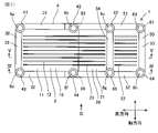
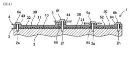
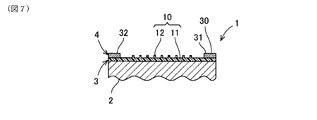
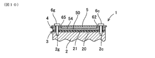
- FIG. 1 It is a figure of the XII-XII cut surface of FIG. It is a top view of the reinforcing member. It is a top view of the first division reinforcement member. It is a figure which looked at the first division reinforcement member from the lower part of FIG. It is a top view of the 2nd division reinforcing member. It is a figure which looked at the 2nd division reinforcement member from the lower part of FIG. It is a figure of the cut surface of the soundproof cover of another example.
- the basic configuration of the soundproof cover 1 will be described with reference to FIG.
- the soundproof cover 1 has a function of covering the object 2 and suppressing the sound generated by the object 2 from being transmitted to the outside. Further, the soundproof cover 1 has a function of radiating the heat of the object 2 to the outside as an additional function.
- the object 2 is, for example, a power source for a vehicle.
- the power source is a vehicle drive motor, a vehicle drive engine, or the like.
- the soundproof cover 1 covers the surface of the object 2, and for example, as shown in FIG. 1, when the object 2 is a drive motor, it covers the outer peripheral surface of the drive motor.
- the soundproof cover 1 covers the outer peripheral surface of the object 2 over the entire circumference, but may have a portion that does not partially cover the outer peripheral surface.
- the soundproof cover 1 includes a sound absorbing sheet 3, a reinforcing member 4, and a ventilation guide 5.
- the sound absorbing sheet 3 is formed in a planar shape by the sound absorbing material and covers the surface of the object 2. Therefore, the soundproofing effect can be obtained by the sound absorbing sheet 3.
- the sound absorbing sheet 3 may be formed in advance in a shape corresponding to the surface shape of the object 2. Further, the sound absorbing sheet 3 may be formed in a plane shape by a deformable material and attached to the surface of the object 2 while being deformed.
- the sound absorbing sheet 3 has a heat radiating performance in addition to the sound absorbing performance.
- the sound absorbing sheet 3 is preferably formed of a material having excellent sound absorbing performance, for example, a foamed resin.
- a foamed resin As an example of the foamed resin, urethane foam, acrylic foam, silicone foam, styrene foam, foamed olefin (foamed PP, foamed PE), foamed PVC, foamed EVA, foamed PA and the like are applied.
- the Asker C hardness of the foamed resin of the sound absorbing sheet 3 is 1 to 60 degrees.
- the sound absorbing sheet 3 may be formed of a non-foaming resin having sound absorbing performance, or may be formed of a metal.
- the sound absorbing sheet 3 is preferably formed of a foamed resin containing a heat conductive material.
- the heat conductive material may extend from the back surface to the front surface of the sound absorbing sheet 3.
- the heat conductive fillers are arranged from the back surface to the front surface of the sound absorbing sheet 3.
- the filling amount of the heat conductive material may be different depending on the position of the sound absorbing sheet 3.
- the filling amount means the filling amount per unit area of the sound absorbing sheet 3 in the surface direction.
- the heat conductive material is a metal plate, it may be insert-molded so as to extend from the back surface to the front surface of the sound absorbing sheet 3.
- the reinforcing member 4 may be engaged with the object 2 by the engaging members 6a, 6b, 6c, 6d. That is, the reinforcing member 4 is engaged in a state where it is arranged at a position where it engages with the engaged portion (2a, 2b, 2c, 2d, 2e, 2f, 2g, 2h in FIGS. 4 and 5) of the object 2.
- the reinforcing member 4 is fixed to the object.
- a fastening member such as a bolt, a locking member such as a claw, or the like is applied to the engaging member 6a-6d.
- the reinforcing member 4 is made of a material having higher rigidity than the sound absorbing sheet 3.
- the material having high rigidity means a material having high rigidity (an index indicating difficulty in bending) when the sound absorbing sheet 3 and the reinforcing member 4 to be compared are formed in the same shape.
- the sound absorbing sheet 3 is formed in a planar shape by, for example, a foamed resin. As described above, when the sound absorbing sheet 3 is made of a sound absorbing material having insufficient rigidity, the effect of positioning the sound absorbing sheet 3 alone on the object 2 is low. Even in such a case, the sound absorbing sheet 3 can be reliably positioned with respect to the object 2 by the reinforcing member 4.
- the reinforcing member 4 is formed of a material having a larger mass per unit volume (hereinafter referred to as "unit mass") than the sound absorbing sheet 3. As described above, in order to enable the reinforcing member 4 to exert the reinforcing function, as a result, the reinforcing member 4 is formed of a material having a unit mass larger than that of the sound absorbing sheet 3.
- the reinforcing member 4 is preferably formed of foamed resin in order to reduce the weight.
- the foamed resin applied to the reinforcing member 4 is different from the foamed resin applied to the sound absorbing sheet 3.
- the foamed resin applied to the reinforcing member 4 urethane foam, acrylic foam, silicone foam, styrene foam, foamed olefin (foamed PP, foamed PE), foamed PVC, foamed EVA, foamed PA and the like are applied. ..
- the Asker C hardness of the foamed resin of the reinforcing member 4 is 60 to 99 degrees. Even if urethane foam is applied to the sound absorbing sheet 3 and the reinforcing member 4, both urethane foams are of different types.
- the reinforcing member 4 is not arranged so as to cover the entire surface of the sound absorbing sheet 3, but is arranged in a state where at least a part of the sound absorbing sheet 3 is exposed.
- the sound absorbing sheet 3 has a heat radiating performance in addition to the sound absorbing performance. Therefore, by exposing the sound absorbing sheet 3, the heat dissipation performance of the sound absorbing sheet 3 can be effectively exhibited.
- the reinforcing member 4 is arranged so as to expose a part of the sound absorbing sheet 3 means that the reinforcing member 4 is arranged so as to face only a part of the outer peripheral surface of the object 2. Therefore, the size of the reinforcing member 4 itself can be made smaller than the size of the outer peripheral surface of the object 2. Even if the reinforcing member 4 has a larger unit mass than the sound absorbing sheet 3, since the region of the reinforcing member 4 is limited to a part of the soundproof cover 1, the influence on the mass increase of the soundproof cover 1 as a whole can be reduced. That is, the weight of the soundproof cover 1 can be reduced.
- the reinforcing member 4 is formed by being a long member.
- the sound absorbing sheet 3 is not configured to cover the entire surface of the sound absorbing sheet 3, and the sound absorbing sheet 3 is provided with at least a part of the sound absorbing sheet 3 exposed. It can be positioned on the object 2.
- the ventilation guide 5 is arranged so as to face each other along at least a part of the surface of the sound absorbing sheet 3.
- the ventilation guide 5 has a space between the ventilation guide 5 and the surface of the sound absorbing sheet 3. Then, the ventilation guide 5 guides the flow of the fluid to and from the surface of the sound absorbing sheet 3. That is, the ventilation guide 5 has a function of enhancing the cooling effect of the sound absorbing sheet 3.
- the ventilation guide 5 is formed in an L shape by, for example, a plate-shaped member, and is fixed to the reinforcing member 4 by the engaging members 6b and 6c.
- the ventilation guide 5 may be formed of, for example, the same material as the reinforcing member 4, or may be formed of a material different from that of the reinforcing member 4. However, it is preferable that the ventilation guide 5 has the same rigidity as the reinforcing member 4.
- the ventilation guide 5 is arranged to face the rear surface of the vehicle in the front-rear direction of the object 2, and guides the fluid flowing from the front to the rear of the vehicle to the rear surface of the object 2. That is, the ventilation guide 5 effectively exerts a cooling effect on the rear surface of the object 2.
- FIGS. 2-FIG. 17 show a diagram in which the soundproof cover 1 is developed in a plane, and FIGS. 2-FIG. 17 will be described below with reference to the diagram.
- the first split sound absorbing sheet 10 includes a first sheet main body 11 and a plurality of heat radiating fins 12.
- the first sheet main body 11 and the heat radiation fins 12 are integrated.
- the first sheet main body 11 is formed in a planar shape, and the back surface of the first sheet main body 11 comes into contact with a part of the front surface of the object 2, for example, a range of about half a circumference.
- the heat radiation fins 12 are provided on the surface of the first divided sound absorbing sheet 10 so as to extend in the surface direction of the first divided sound absorbing sheet 10. That is, the heat radiation fins 12 are provided so as to project outward from the surface of the first sheet main body 11.
- the plurality of heat radiation fins 12 are formed in, for example, ridges extending in the circumferential direction of the outer peripheral surface of the object 2, and are arranged at a distance in the axial direction of the outer peripheral surface of the object 2.
- the shape of the heat radiating fin 12 may be wavy, may be formed so as to extend in the axial direction of the outer peripheral surface of the object 2, or may be formed in the circumferential direction and the axial direction of the outer peripheral surface of the object 2. On the other hand, it may be formed so as to extend in the direction of inclination.
- the heat conductive material is formed on the first sheet body 11 from the back surface of the first sheet body 11 to the tip of the heat radiation fin 12. It is good to extend continuously in the direction of the surface normal. As a result, high heat dissipation performance can be exhibited by continuously arranging the heat conductive material in the range from the surface of the object 2 to the tip of the heat dissipation fin 12.
- a conductive filler is suitable for the heat conductive material in this case.
- the heat conductive material (second heat conductive material) extends from the heat radiation fins 12 on the tip side of the heat radiation fins 12. It is good to extend it continuously in the direction. As a result, the heat conductive material is continuously arranged in the range from one end side to the other end side in the extending direction of the heat radiating fin 12, so that high heat radiating performance can be exhibited even in the surface direction.
- a metal foil such as copper, stainless steel, steel, or aluminum
- a metal film such as an aluminum vapor-deposited film, a conductive filler, a heat conductive resin film, or the like can be used.
- the metal foil or the metal film and the resin film may be laminated.
- the heat conductive material may be provided only in a specific region of the plurality of heat radiation fins or only in the specific heat radiation fins, or may be arranged on the outer surface on the tip end side or the side surface of the heat radiation fins.
- the second split sound absorbing sheet 20 includes a second sheet main body 21 and a plurality of heat radiating fins 22 and 23.
- the second seat body 21 and the heat radiation fins 22 and 23 are integrated.
- the second sheet main body 21 is formed in a planar shape, and the back surface of the second sheet main body 21 comes into contact with a part of the front surface of the object 2, for example, a range of about half a circumference.
- the second sheet main body 21 is arranged so as to abut against the first sheet main body 11 in the circumferential direction of the object 2. That is, the first sheet main body 11 and the second sheet main body 21 are continuously arranged in the circumferential direction of the object 2.
- the heat radiating fins 22 and 23 are provided on the surface of the second divided sound absorbing sheet 20 so as to extend in the surface direction of the second divided sound absorbing sheet 20. That is, the heat radiation fins 22 and 23 are provided so as to project outward from the surface of the second sheet main body 21.
- the plurality of heat radiation fins 22 and 23 are formed in, for example, ridges extending in the circumferential direction of the outer peripheral surface of the object 2, and are arranged at a distance in the axial direction of the outer peripheral surface of the object 2.
- the shape of the heat radiation fins 22 and 23 may be wavy, may be formed so as to extend in the axial direction of the outer peripheral surface of the object 2, or may be formed so as to extend in the circumferential direction and axis of the outer peripheral surface of the object 2. It may be formed so as to extend in a direction inclined with respect to a direction.
- the heat radiation fins 23 of the second split sound absorbing sheet 20 are continuously arranged with the heat radiation fins 12 of the first split sound absorbing sheet 10 in the circumferential direction of the object 2. That is, the ends of the heat radiating fins 12 of the first divided sound absorbing sheet 10 and the ends of the heat radiating fins 23 of the second divided sound absorbing sheet 20 are arranged so as to abut against each other.
- the heat conductive material is formed from the back surface of the second sheet body 21 to the tips of the heat radiation fins 22 and 23, and the second sheet body is formed. It is preferable to extend it continuously in the direction of the plane normal of 21. As a result, high heat dissipation performance can be exhibited by continuously arranging the heat conductive material in the range from the surface of the object 2 to the tips of the heat dissipation fins 22 and 23.
- a conductive filler is suitable for the heat conductive material in this case.
- the heat conductive material (second heat conductive material) is placed on the tip side of the heat radiation fins 22 and 23. It is preferable that the 23 is continuously extended in the extending direction. As a result, the heat conductive material is continuously arranged in the range from one end side to the other end side in the extending direction of the heat radiating fins 22 and 23, so that high heat radiating performance can be exhibited even in the surface direction. ..
- the heat conductive material in this case, a metal foil such as copper, stainless steel, steel, or aluminum, a metal film such as an aluminum vapor-deposited film, a conductive filler, a heat conductive resin film, or the like can be used. Further, the metal foil or the metal film and the resin film may be laminated.
- the heat conductive material may be provided only in a specific region of the plurality of heat radiation fins or only in the specific heat radiation fins, or may be arranged on the outer surface on the tip end side or the side surface of the heat radiation fins.
- the surface layer of the first divided sound absorbing sheet 10 and the second divided sound absorbing sheet 20 is in a closed cell state in which the foamed resin cells are closed, and the back layer is in an open cell state in which the foamed resin cells are open.
- the surface layer in a closed cell state pressure loss when the fluid flows can be suppressed, so that heat dissipation performance can be improved.
- the back layer in an open cell state the sound absorption performance can be improved. That is, with the above configuration, the sound absorption performance and the heat dissipation performance can be improved.
- the surface of the object 2 has a curved surface that is convex outward, such as an outer peripheral surface of a cylinder. Therefore, among the rectangular frame members (31, 33, 51-53), the portions (31, 32, 51, 52) extending in the circumferential direction of the object 2 are elongated from one end side to the other end side. It is formed in a curved shape that is convex outward toward the outside, and is arranged along the curved surface of the object 2. On the other hand, among the rectangular frame members (31-33, 51-53), the portions (33, 53) and the auxiliary members (54) extending in the axial direction of the object 2 are elongated from one end side to the other end.
- the portion (33, 53, 54) is not limited to a linear shape, but is formed in a shape corresponding to the shape of the outer peripheral surface of the object 2 in the axial direction.
- the first division reinforcing member 30 includes circumferential members 31, 32 and axial members 33.
- the circumferential member 31 of the first divided sound absorbing member 30 is arranged along a part of the edge portion of the first divided sound absorbing sheet 10 constituting the sound absorbing sheet 3. Specifically, the circumferential member 31 is arranged so as to overlap a part of the edge portion on the surface of the first sheet main body 11 of the first divided sound absorbing sheet 10.
- the other circumferential member 32 is arranged at the edge of the first divided sound absorbing sheet 10 facing the edge of the first divided sound absorbing sheet 10 in which the circumferential member 31 is arranged. That is, the circumferential members 31 and 32 are arranged at different positions facing the axial direction of the object 2 on the edge of the first divided sound absorbing sheet 10.
- the circumferential members 31 and 32 are arranged apart from each other in the surface direction of the first divided sound absorbing sheet 10. Then, the circumferential member 32 is arranged so as to overlap a part of the edge portion on the surface of the first sheet main body 11 of the first divided sound absorbing sheet 10.
- the circumferential member 32 constituting the first split reinforcing member 30 is provided with an engaging portion 43 at a portion to be coupled to the axial member 33.
- the engaging portion 43 forms, for example, a cylindrical seat surface, and is arranged at a position where the object 2 engages with the engaged portion 2e (bolt screw hole, second engaged portion). ..
- the engaging portion 43 has a hole through which a bolt as an engaging member 6e (shown in FIG. 2) is inserted, and is positioned on the engaged portion 2e of the object 2 by the engaging member 6e. Will be done.
- the engaged portions 2a and 2b to which the engaging portions 41 and 42 are engaged are formed at different positions from the engaged portions 2e to which the engaging portions 43 are engaged.
- the circumferential member 32 is provided with an engaging portion 44 at the other end in the long direction.
- the engaging portion 44 forms, for example, a cylindrical seat surface, and is arranged at a position where the object 2 engages with the engaged portion 2f (bolt screw hole, second engaged portion). ..
- the engaging portion 44 has a hole through which a bolt as an engaging member 6f (shown in FIG. 2) is inserted, and is positioned on the engaged portion 2f of the object 2 by the engaging member 6f. Will be done.
- the engaging portion 44 has a different height with respect to the central portion of the circumferential member 32.
- the engaging portion 44 is located away from the first split sound absorbing sheet 10 in the plane normal direction.
- the other circumferential member 52 includes an edge portion of the edge portion of the first divided sound absorbing sheet 10 facing the edge portion of the first divided sound absorbing sheet 10 in which the circumferential member 51 is arranged, and a second divided sound absorbing sheet 10.
- the circumferential member 51 is arranged at the edge portion facing the edge portion of the second split sound absorbing sheet 20 in which the circumferential member 51 is arranged. That is, the circumferential member 52 is also arranged along a part of the edge portion of both the first divided sound absorbing sheet 10 and the second divided sound absorbing sheet 20 constituting the sound absorbing sheet 3.
- the circumferential members 51 and 52 are arranged at different positions facing the axial direction of the object 2 on the edges of the first divided sound absorbing sheet 10 and the second divided sound absorbing sheet 20. In this way, the circumferential members 51 and 52 are arranged apart from each other in the surface direction of the first divided sound absorbing sheet 10 and the second divided sound absorbing sheet 20.
- the circumferential member 52 is a part of the edge portion on the surface of the first sheet main body 11 of the first divided sound absorbing sheet 10 and the edge portion on the surface of the second sheet main body 21 of the second divided sound absorbing sheet 20. It is placed on top of a part of.
- the axial member 53 of the second split reinforcing member 50 is formed of a long member, and one ends of the circumferential members 51 and 52 are connected to each other.
- the axial member 53 extends in the axial direction of the object 2. That is, the axial member 53 is coupled and arranged with respect to each of the circumferential members 51 and 52. In this way, the axial member 53 is arranged along a part of the edge portion of the second split sound absorbing sheet 20. Specifically, the axial member 53 is arranged so as to overlap a part of the edge portion on the surface of the second sheet main body 21 of the second divided sound absorbing sheet 20.
- the ends of the axial member 53 and the circumferential members 51 and 52 are connected to each other, they may be arranged so as to intersect each other like a cross.
- the axial member 54 of the second split reinforcing member 50 is formed of a long member, and connects the intermediate portions of the circumferential members 51 and 52 in the long direction.
- the axial member 54 extends in the axial direction of the object 2. That is, the axial member 54 is coupled and arranged with respect to each of the circumferential members 51 and 52. Further, the axial member 54 is arranged so as to overlap a part of the surface of the second sheet main body 21 of the second divided sound absorbing sheet 20. Although the ends of the axial member 54 and the circumferential members 51 and 52 are connected to each other, they may be arranged so as to intersect each other like a cross.
- the circumferential member 51 constituting the second split reinforcing member 50 is provided with an engaging portion 61 at a portion to be coupled to the axial member 53, that is, at one end in the elongated direction.
- the circumferential member 51 includes an engaging portion 62 at a portion that is coupled to the axial member 54, that is, at an intermediate portion in the elongated direction.
- the engaging portions 61 and 62 form, for example, a cylindrical seat surface, and are positioned to engage the engaged portions 2d and 2c (bolt screw holes, first engaged portions) of the object 2. Is placed in.
- the engaging portions 61 and 62 have holes through which bolts as engaging members 6d and 6c (shown in FIG.
- the engaging portions 61 and 62 may have a configuration in which they are directly locked to the engaged portions 2d and 2c of the object 2 by a claw or the like.
- the circumferential member 52 constituting the second split reinforcing member 50 is provided with an engaging portion 64 at a portion to be coupled to the axial member 53, that is, at one end in the elongated direction.
- the circumferential member 52 includes an engaging portion 65 at a portion that is coupled to the axial member 54, that is, at an intermediate portion in the elongated direction.
- the engaging portions 64 and 65 form, for example, a cylindrical seat surface, and are positioned to engage the engaged portions 2h and 2g (bolt screw holes, second engaged portions) of the object 2. Is placed in.
- the engaging portions 64 and 65 have holes for inserting bolts as engaging members 6h and 6g (shown in FIG.
- the engaging portions 64 and 65 may have a configuration in which they are directly locked to the engaged portions 2h and 2g of the object 2 by a claw or the like.
- the circumferential member 52 is provided with an engaging portion 66 at the other end in the long direction.
- the engaging portion 66 forms, for example, a cylindrical seat surface, and is arranged at a position where the object 2 engages with the engaged portion 2f (bolt screw hole, second engaged portion). ..
- the engaging portion 66 is arranged so as to overlap the engaging portion 44 of the first split reinforcing member 30.
- the engaging portion 66 has a hole through which a bolt as an engaging member 6f (shown in FIG. 2) is inserted, and the engaging member 6f together with the engaging portion 44 of the object 2 It is positioned on the engaged portion 2f.
- the sound absorbing sheet 3 is composed of a plurality of divided bodies 10 and 20, and the reinforcing member 4 is composed of a plurality of divided bodies 30 and 50.
- the soundproof cover 1 can be easily attached to the object 2 when the entire circumference of the object 2 is covered.
- the circumferential members 51 and 52 of the second divided reinforcing member 50 are arranged so as to straddle the plurality of divided bodies 10 and 20.
- the plurality of divided bodies 10 and 20 constituting the sound absorbing sheet 3 can be reliably positioned.
- the reinforcing member 4 is integrated with the peripheral surface (end surface in the surface direction) of the sound absorbing sheet 3. In this case, the reinforcing member 4 is fixed to the object 2 without interposing the sound absorbing sheet 3. By fixing the reinforcing member 4 to the object 2, the sound absorbing sheet 3 integrated with the reinforcing member 4 is positioned with respect to the object 2.
- the circumferential members 31, 32 and the axial members 33 constituting the first split reinforcing member 30 are integrated at adjacent positions on the peripheral surface of the first split sound absorbing sheet 10.
- the circumferential members 51, 52 and the axial member 53 constituting the second split reinforcing member 50 are integrated at adjacent positions on the peripheral surface of the second split sound absorbing sheet 20.
- the axial member 54 constituting the second split reinforcing member 50 may be integrated on the surface of the second split sound absorbing sheet 20.
- the axial member 54 constituting the second divided reinforcing member 50 may also be integrated with the peripheral surface of the divided sound absorbing sheet 3.
- each of the elongated members (31, 32, 33, 51, 52, 53, 54) constituting the reinforcing member 4 is integrated with the peripheral surface of the sound absorbing sheet 3. ..
- each of the elongated members (31, 32, 33, 51, 52, 53, 54) constituting the reinforcing member 4 may be integrated on the surface of the sound absorbing sheet 3.
Landscapes
- Engineering & Computer Science (AREA)
- Physics & Mathematics (AREA)
- Acoustics & Sound (AREA)
- Mechanical Engineering (AREA)
- Chemical & Material Sciences (AREA)
- Combustion & Propulsion (AREA)
- General Engineering & Computer Science (AREA)
- Multimedia (AREA)
- Soundproofing, Sound Blocking, And Sound Damping (AREA)
- Vehicle Interior And Exterior Ornaments, Soundproofing, And Insulation (AREA)
- Motor Or Generator Frames (AREA)
Abstract
対象物(2)を被覆する防音カバー(1)は、吸音材により面状に形成され対象物(2)の表面を被覆する吸音シート(3)と、対象物(2)の被係合部(2a,2b,2c,2d,2e,2f,2g,2h)に係合する位置に配置され、吸音シート(3)の少なくとも一部を露出させた状態で吸音シート(3)を対象物(2)に対して位置決めする補強部材(4)とを備える。補強部材(4)は、長尺状部材であり、対象物(2)の第一被係合部に係合する位置に配置される第一補強部(31)と、長尺状部材であり、第一補強部(31)とは異なる位置に配置される第二補強部(32,33)とを備える。
Description
本開示は、防音カバーに関するものである。
特許文献1-4に記載されているように、車両の駆動源に防音カバーを取り付けることが知られている。これらの防音カバーにおいては、高剛性のカバー本体に、吸音材を取り付けている。また、特許文献5には、樹脂又はエラストマーからなる母材に、磁性フィラーが配向された防音カバーが記載されている。
しかし、防音カバーが高剛性のカバー本体を有することにより、防音カバー全体の質量が大きくなってしまう。カバー本体を設けない構成とすることにより、防音カバーの軽量化を図ることが考えられる。しかし、カバー本体を設けないと、吸音材を対象物に確実に位置決めすることができない場合がある。
本開示は、軽量化を図ると共に、吸音材を対象物に確実に位置決めすることができる防音カバーを提供することを目的とする。
本開示の一態様は、対象物を被覆する防音カバーであって、
吸音材により面状に形成され、前記対象物の表面を被覆する吸音シートと、
前記対象物の被係合部に係合する位置に配置され、前記吸音シートの少なくとも一部を露出させた状態で前記吸音シートを前記対象物に対して位置決めする補強部材と、
を備え、
前記補強部材は、
長尺状部材であり、前記対象物の第一被係合部に係合する位置に配置される第一補強部と、
長尺状部材であり、前記第一補強部とは異なる位置に配置される第二補強部と、
を備える、防音カバーにある。
吸音材により面状に形成され、前記対象物の表面を被覆する吸音シートと、
前記対象物の被係合部に係合する位置に配置され、前記吸音シートの少なくとも一部を露出させた状態で前記吸音シートを前記対象物に対して位置決めする補強部材と、
を備え、
前記補強部材は、
長尺状部材であり、前記対象物の第一被係合部に係合する位置に配置される第一補強部と、
長尺状部材であり、前記第一補強部とは異なる位置に配置される第二補強部と、
を備える、防音カバーにある。
上記防音カバーを構成する吸音シートは、吸音材により面状に形成されており、対象物の表面を被覆する。従って、吸音シートによって、防音効果を得ることができる。ここで、吸音シートは、補強部材によって、対象物に位置決めされている。従って、吸音シートが十分に剛性を有しない吸音材により形成されているとしても、補強部材によって吸音シートを確実に対象物に位置決めすることができる。
ここで、補強部材は、吸音シートの少なくとも一部を露出させた状態としている。つまり、補強部材は、吸音シートの全面を被覆していない。従って、補強部材の領域が防音カバーの一部領域に限られるため、防音カバーの軽量化を図ることができる。
そして、補強部材は、少なくとも、長尺状部材である第一補強部と長尺状部材である第二補強部とを備える。このように、第一補強部及び第二補強部を長尺状部材とすることにより、上記のように、吸音シートの全面を被覆する構成とはならず、吸音シートの少なくとも一部を露出させた状態で、吸音シートを対象物に位置決めすることができる。
なお、特許請求の範囲に記載した括弧内の符号は、後述する実施形態に記載の具体的手段との対応関係を示すものであり、本発明の技術的範囲を限定するものではない。
(1.防音カバー1の基本構成)
防音カバー1の基本構成について、図1を参照して説明する。防音カバー1は、対象物2を被覆して、対象物2にて発生する音が外部へ伝達することを抑制する機能を有する。さらに、防音カバー1は、追加機能として、対象物2の熱を外部へ放熱する機能を有する。対象物2は、例えば、車両の動力源とする。動力源としては、車両の駆動用モータ、車両の駆動用エンジン等である。
防音カバー1の基本構成について、図1を参照して説明する。防音カバー1は、対象物2を被覆して、対象物2にて発生する音が外部へ伝達することを抑制する機能を有する。さらに、防音カバー1は、追加機能として、対象物2の熱を外部へ放熱する機能を有する。対象物2は、例えば、車両の動力源とする。動力源としては、車両の駆動用モータ、車両の駆動用エンジン等である。
ここで、図1においては、対象物2は、車両の駆動用モータである場合を示す。また、図1の駆動用モータは、円筒外周面を有する場合を例示している。ただし、駆動用モータの外周面は、円筒面に限られるものではなく、適宜凹凸状に形成されるようにしても良い。また、例えば、駆動用モータの回転軸線が車両の左右方向に一致するように配置され、図1の左側が車両前方であり、右側が車両後方である。一般に、車両前方面は、車両走行によって、空気流を直接受けることが可能な領域となり、車両後方面は、当該空気流を直接受けない領域となる。
防音カバー1は、対象物2の表面を被覆しており、例えば、図1に示すように、対象物2が駆動用モータの場合には駆動用モータの外周面を被覆する。防音カバー1は、対象物2の外周面を全周に亘って被覆しているが、一部に被覆しない部位を有するようにしても良い。
防音カバー1は、吸音シート3、補強部材4、通風ガイド5を備える。吸音シート3は、吸音材により面状に形成され、対象物2の表面を被覆する。従って、吸音シート3によって、防音効果を得ることができる。吸音シート3は、予め対象物2の表面形状に対応した形状に形成するようにしても良い。また、吸音シート3は、変形可能な材料により平面状に形成し、変形させながら対象物2の表面に取り付けるようにしても良い。吸音シート3は、吸音性能に加えて、放熱性能を有する。
吸音シート3は、吸音性能に優れた材料、例えば、発泡樹脂により形成するのが好適である。発泡樹脂の例として、ウレタンフォーム、アクリルフォーム、シリコーンフォーム、スチレンフォーム、発泡オレフィン(発泡PP、発泡PE)、発泡PVC、発泡EVA、発泡PA等が適用される。そして、吸音シート3の発泡樹脂のアスカーC硬度は、1~60度である。なお、吸音シート3は、吸音性能を有する非発泡樹脂により形成するようにしても良いし、金属により形成するようにしても良い。非発泡樹脂の例として、ポリアミド樹脂、オレフィン樹脂、スチレン樹脂、ウレタン樹脂、シリコーン樹脂、アクリル樹脂、ポリ塩化ビニル樹脂、ポリエチレン樹脂、ポリエチレンテレフタレート樹脂、ポリカーボネート樹脂、ポリプロピレン樹脂、ABS樹脂、EVA樹脂、炭素繊維プラスチック(FRP、CFRP)等が適用される。また、金属の例として、鉄、アルミニウム、SUS、銅、及びその合金が適用される。ただし、吸音性能としては優れている発泡樹脂が好適である。
さらに、吸音シート3が放熱性能を有するようにするために、吸音シート3は、熱伝導材を含む発泡樹脂により形成されると良い。熱伝導材は、吸音シート3の裏面から表面に向かって延在されるようにすると良い。例えば、熱伝導材が熱伝導フィラーである場合には、熱伝導フィラーが、吸音シート3の裏面から表面に向かって配列される。さらには、熱伝導材の充填量が、吸音シート3の位置によって異なるようにしても良い。例えば、車両前方面より車両後方面の方が冷却されにくいため、車両前方面よりも車両後方面における熱伝導材の充填量を多くすると良い。なお、ここでの充填量とは、吸音シート3の面方向における単位面積当たりの充填量を意味する。また、熱伝導材が金属板である場合には、吸音シート3の裏面から表面に向かって延在するようにインサート成形されるようにすると良い。
図1においては、吸音シート3は、別体に形成された複数の分割体10,20(第一分割吸音シート10及び第二分割吸音シート20)により構成される。それぞれの分割体10,20により、対象物2の外周面の概ね半分程度を被覆する。対象物2の外周面において周方向に隣り合う分割体10,20は、対象物2の外周面の周方向に突き合わせて配置されている。
補強部材4は、吸音シート3を対象物2に対して位置決めする。補強部材4は、吸音シート3とは別体に形成され、吸音シート3の表面上に配置されることにより、補強部材4と対象物2との間に吸音シート3を挟んで配置されるようにしても良い。また、補強部材4は、吸音シート3に一体化され、吸音シート3の表面上に配置されることにより、補強部材4と対象物2との間に吸音シート3を挟んで配置されるようにしても良い。また、補強部材4は、吸音シート3の周面に一体化されるようにしても良い。
また、補強部材4は、対象物2への固定方法として、例えば、図1に示すように、係合部材6a,6b,6c,6dにより対象物2に係合するようにしても良い。つまり、補強部材4は、対象物2の被係合部(図4,5における2a,2b,2c,2d,2e,2f,2g,2h)に係合する位置に配置された状態で、係合部材6a-6dにより対象物2に係合されることで、補強部材4が対象物に固定された状態となる。係合部材6a-6dには、例えば、ボルト等の締結部材や爪等の係止部材等が適用される。
補強部材4は、吸音シート3よりも剛性の高い材料により形成されている。剛性の高い材料とは、比較対象である吸音シート3及び補強部材4を同一形状に形成した場合に剛性(曲げにくさを表す指標)が高い材料を意味する。吸音シート3は例えば発泡樹脂により面状に形成されている。このように、吸音シート3が十分に剛性を有しない吸音材により形成されている場合、吸音シート3のみでは対象物2への位置決め効果が低い。このような場合であっても、補強部材4によって、吸音シート3を対象物2に対して確実に位置決めすることができる。
さらに、補強部材4は、吸音シート3よりも単位体積当たりの質量(以下、「単位質量」と称する)が大きな材料により形成される。上述したように、補強部材4が補強機能を発揮できるようにするために、結果として、補強部材4が、吸音シート3よりも単位質量が大きな材料により形成される。
補強部材4は、軽量化を図るために、発泡樹脂により形成されると良い。ただし、補強部材4に適用される発泡樹脂は、吸音シート3に適用される発泡樹脂とは異なる。例えば、補強部材4に適用される発泡樹脂の例として、ウレタンフォーム、アクリルフォーム、シリコーンフォーム、スチレンフォーム、発泡オレフィン(発泡PP、発泡PE)、発泡PVC、発泡EVA、発泡PA等が適用される。そして、補強部材4の発泡樹脂のアスカーC硬度は、60~99度である。なお、吸音シート3及び補強部材4に、ウレタンフォームを適用したとしても、両者のウレタンフォームは異なる種類である。
また、補強部材4は、発泡樹脂の他に、発泡ゴム、非発泡樹脂、又は、金属等を適用することもできる。発泡ゴムの例として、発泡EPDM、発泡CR、発泡NBR/PVC、発泡ACM等が適用される。また、非発泡樹脂の例として、ポリアミド樹脂、オレフィン樹脂、スチレン樹脂、ウレタン樹脂、シリコーン樹脂、アクリル樹脂、ポリ塩化ビニル樹脂、ポリエチレン樹脂、ポリエチレンテレフタレート樹脂、ポリカーボネート樹脂、ポリプロピレン樹脂、ABS樹脂、EVA樹脂、炭素繊維プラスチック(FRP、CFRP)等が適用される。また、金属の例として、鉄、アルミニウム、SUS、銅、及びその合金等が適用される。これらの場合の補強部材は、発泡樹脂よりも硬度の高いゴム、樹脂又は金属により形成される。ただし、軽量化の観点から発泡樹脂が好適である。
また、補強部材4は、吸音シート3の表面を全面に亘って被覆するように配置されておらず、吸音シート3の少なくとも一部を露出させた状態で配置されている。吸音シート3は、上述したように、吸音性能に加えて、放熱性能を有する。従って、吸音シート3が露出されることによって、吸音シート3による放熱性能を効果的に発揮させることができる。
補強部材4は、吸音シート3の一部を露出させるように配置されるということは、対象物2の外周面の一部のみに対向するように配置されているということになる。従って、対象物2の外周面の大きさに比べて、補強部材4自身の大きさを小さくすることができる。補強部材4が吸音シート3よりも単位質量が大きいとしても、補強部材4の領域が防音カバー1の一部に限られるため、防音カバー1全体としての質量増加への影響を小さくできる。つまり、防音カバー1の軽量化を図ることができる。
補強部材4は、別体に形成された複数の分割体30,50(第一分割補強部材30及び第二分割補強部材50)により構成される。第一分割補強部材30は、主として第一分割吸音シート10を位置決めし、第二分割補強部材50は、主として第二分割吸音シート20を位置決めする。また、第一分割補強部材30と第二分割補強部材50とは、係合部材6bにより、相互に固定されている。
なお、後述するが、補強部材4は、長尺状部材であるにより形成している。補強部材4を長尺状部材とすることにより、上記のように、吸音シート3の全面を被覆する構成とはならず、吸音シート3の少なくとも一部を露出させた状態で、吸音シート3を対象物2に位置決めすることができる。
通風ガイド5は、吸音シート3の表面の少なくとも一部に沿って対向して配置されている。通風ガイド5は、吸音シート3の表面との間に空間を有している。そして、通風ガイド5は、吸音シート3の表面との間において流体の流通をガイドする。つまり、通風ガイド5は、吸音シート3の冷却効果を高める機能を有する。
通風ガイド5は、図1に示すように、例えば、板状部材によりL字に形成されており、係合部材6b,6cにより補強部材4に固定される。通風ガイド5は、例えば、補強部材4と同一材料により形成されるようにしても良いし、補強部材4とは異なる材料により形成しても良い。ただし、通風ガイド5は、補強部材4と同程度の剛性を有すると良い。
特に、通風ガイド5は、対象物2における車両の前後方向の後方面に対向して配置され、車両の前方から後方に向かって流通する流体を対象物2における後方面へガイドする。つまり、通風ガイド5は、対象物2の後方面における冷却効果を効果的に発揮する。
(2.防音カバー1の詳細構成)
防音カバー1の詳細構成について、図2-図17を参照して説明する。防音カバー1は、図1に示したように、対象物2の表面形状に応じた形状に形成される。ただし、説明を容易にするために、図2-図17には、防音カバー1を平面状に展開した状態の図を示しており、以下には、当該図を用いて説明する。
防音カバー1の詳細構成について、図2-図17を参照して説明する。防音カバー1は、図1に示したように、対象物2の表面形状に応じた形状に形成される。ただし、説明を容易にするために、図2-図17には、防音カバー1を平面状に展開した状態の図を示しており、以下には、当該図を用いて説明する。
防音カバー1は、上述したように、吸音シート3、補強部材4、通風ガイド5を備える。以下においては、吸音シート3及び補強部材4について、詳細に説明する。吸音シート3は、本例では、別体に形成された2つの分割体(第一分割吸音シート10及び第二分割吸音シート20)により構成される。なお、吸音シート3は、3以上の分割体により構成されるようにしても良いし、1つのシートのみにより構成されるようにしても良い。
第一分割吸音シート10は、第一シート本体11、及び、複数の放熱フィン12を備える。第一シート本体11と放熱フィン12とが一体化されている。第一シート本体11は、面状に形成され、第一シート本体11の裏面が、対象物2の表面のうちの一部、例えば半周分程度の範囲に接触する。
放熱フィン12は、第一分割吸音シート10の表面に、第一分割吸音シート10の面方向に延在するように設けられる。すなわち、放熱フィン12は、第一シート本体11の表面から外側に突出するように設けられる。複数の放熱フィン12は、例えば、対象物2の外周面の周方向に延在する突条に形成され、対象物2の外周面の軸方向に距離を隔てて配列されている。ただし、放熱フィン12の形状は、波状としても良いし、対象物2の外周面の軸方向に延在するように形成しても良いし、対象物2の外周面の周方向及び軸方向に対して傾斜する方向に延在するように形成しても良い。
第一分割吸音シート10は、例えば、熱伝導材を含む発泡樹脂により形成される場合において、熱伝導材が、第一シート本体11の裏面から放熱フィン12の先端において、第一シート本体11の面法線方向に連続して延在されるようにすると良い。これにより、対象物2の表面から放熱フィン12の先端に至る範囲に、連続して熱伝導材が配置されることにより、高い放熱性能を発揮することができる。この場合の熱伝導材には、導電性フィラーが好適である。
第一分割吸音シート10は、例えば、熱伝導材を含む発泡樹脂により形成される場合において、熱伝導材(第二熱伝導材)が、放熱フィン12の先端側において、放熱フィン12の延在方向に連続して延在されるようにすると良い。これにより、放熱フィン12の延在方向の一端側から他端側に至る範囲に、連続して熱伝導材が配置されることにより、面方向においても高い放熱性能を発揮することができる。この場合の熱伝導材には、銅、ステンレス、鋼、アルミニウム等の金属箔、アルミ蒸着フィルム等の金属フィルム、導電性フィラー、熱伝導性樹脂フィルム等を用いることができる。また、金属箔や金属フィルムと樹脂フィルムとを積層させても良い。なお、熱伝導材は、複数の放熱フィンにおける特定の領域や、特定の放熱フィンのみに設けても良く、また、放熱フィンの先端側又は側面の外表面に配置しても良い。
第二分割吸音シート20は、図2や図3等に示すように、第二シート本体21、及び、複数の放熱フィン22,23を備える。第二シート本体21と放熱フィン22,23とが一体化されている。第二シート本体21は、面状に形成され、第二シート本体21の裏面が、対象物2の表面のうちの一部、例えば半周分程度の範囲に接触する。第二シート本体21は、第一シート本体11に対して、対象物2の周方向において突き合わせて配置されている。つまり、第一シート本体11と第二シート本体21とは、対象物2の周方向において連続して配置されている。
放熱フィン22,23は、第二分割吸音シート20の表面に、第二分割吸音シート20の面方向に延在するように設けられる。すなわち、放熱フィン22,23は、第二シート本体21の表面から外側に突出するように設けられる。複数の放熱フィン22,23は、例えば、対象物2の外周面の周方向に延在する突条に形成され、対象物2の外周面の軸方向に距離を隔てて配列されている。ただし、放熱フィン22,23の形状は、波状としても良いし、対象物2の外周面の軸方向に延在するように形成しても良いし、対象物2の外周面の周方向及び軸方向に対して傾斜する方向に延在するように形成しても良い。
また、第二分割吸音シート20の放熱フィン23は、第一分割吸音シート10の放熱フィン12と、対象物2の周方向において連続して配置されている。つまり、第一分割吸音シート10の放熱フィン12の端と第二分割吸音シート20の放熱フィン23の端とが、突き合わせて配置されている。
第二分割吸音シート20は、例えば、熱伝導材を含む発泡樹脂により形成される場合において、熱伝導材が、第二シート本体21の裏面から放熱フィン22,23の先端において、第二シート本体21の面法線方向に連続して延在されるようにすると良い。これにより、対象物2の表面から放熱フィン22,23の先端に至る範囲に、連続して熱伝導材が配置されることにより、高い放熱性能を発揮することができる。この場合の熱伝導材には、導電性フィラーが好適である。
第二分割吸音シート20は、例えば、熱伝導材を含む発泡樹脂により形成される場合において、熱伝導材(第二熱伝導材)が、放熱フィン22,23の先端側において、放熱フィン22,23の延在方向に連続して延在されるようにすると良い。これにより、放熱フィン22,23の延在方向の一端側から他端側に至る範囲に、連続して熱伝導材が配置されることにより、面方向においても高い放熱性能を発揮することができる。この場合の熱伝導材には、銅、ステンレス、鋼、アルミニウム等の金属箔、アルミ蒸着フィルム等の金属フィルム、導電性フィラー、熱伝導性樹脂フィルム等を用いることができる。また、金属箔や金属フィルムと樹脂フィルムとを積層させても良い。なお、熱伝導材は、複数の放熱フィンにおける特定の領域や、特定の放熱フィンのみに設けても良く、また、放熱フィンの先端側又は側面の外表面に配置しても良い。
また、第一分割吸音シート10及び第二分割吸音シート20が発泡樹脂により形成されている場合には、以下のようにすると良い。第一分割吸音シート10及び第二分割吸音シート20の表層は、発泡樹脂のセルが閉じたクローズドセル状態とされ、裏層は、発泡樹脂のセルが開いたオープンセル状態とされると良い。表層をクローズドセル状態とすることで、流体が流通する際の圧損を抑制できるため、放熱性能を高くすることができる。一方、裏層をオープンセル状態とすることで、吸音性能を高くすることができる。つまり、上記構成により、吸音性能及び放熱性能を良好とすることができる。
補強部材4は、本例では、別体に形成された2つの分割体(第一分割補強部材30及び第二分割補強部材50)により構成される。なお、補強部材4は、3以上の分割体により構成されるようにしても良いし、1つの部材のみにより構成されるようにしても良い。
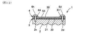
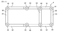
補強部材4は、図13に示すように、長尺状部材により形成されており、全体としては、矩形枠部材(31-33,51-53)、矩形枠部材(31-33,51-53)の枠内に位置する補助部材(54)を備える。矩形枠部材(31-33,51-53)は、対象物2の周方向に延在する部位(31,32,51,52)と、対象物2の軸方向に延在する部位(33,53)とを備える。つまり、矩形枠部材(31-33,51-53)のそれぞれが、矩形のそれぞれの一辺を形成する。部材31,51(第一補強部)、部材32,52(第二補強部)、部材33(第二補強部、第三補強部)、及び、部材53(第二補強部、第四補強部)が、矩形のそれぞれの一辺を形成する。また、補助部材(54)は、対象物2の軸方向に延在する。
対象物2の表面は、例えば、円筒外周面等のように、外側に凸となる湾曲面を有している。そこで、矩形枠部材(31-33,51-53)のうち、対象物2の周方向に延在する部位(31,32,51,52)は、長尺状の一端側から他端側に向かって外側に凸となる湾曲した形状に形成され、対象物2の湾曲面に沿って配置される。一方、矩形枠部材(31-33,51-53)のうち、対象物2の軸方向に延在する部位(33,53)及び補助部材(54)は、長尺状の一端側から他端側に向かって例えば直線状に形成され、対象物2の外周面の軸方向に沿って配置される。ただし、当該部位(33,53,54)は、直線状に限られるのではなく、対象物2の外周面の軸方向の形状に応じた形状に形成される。
そして、矩形枠部材(31-33,51-53)は、図2に示すように、吸音シート3の外周縁に対応する位置に位置する。つまり、本例においては、矩形枠部材(31-33,51-53)は、図2に示すように、吸音シート3の表面上における外周縁全周に亘って配置されており、図3-図12に示すように、矩形枠部材(31-33,51-53)と対象物2との間に吸音シート3を挟んで配置される。
以下に、補強部材4を構成する第一分割補強部材30及び第二分割補強部材50のそれぞれについて説明する。第一分割補強部材30については、図14及び図15を参照して説明する。第一分割補強部材30は、周方向部材31,32と軸方向部材33を備える。
周方向部材31,32は、長尺状部材によりそれぞれ形成されており、対象物2の周方向に延在する。つまり、周方向部材31,32は、対象物2の外周面における外側凸状の周方向面に沿った形状に形成されている。周方向部材31,32は、対象物2の軸方向に離間している。
第一分割補強部材30の周方向部材31は、吸音シート3を構成する第一分割吸音シート10の縁部の一部に沿って配置される。詳細には、周方向部材31は、第一分割吸音シート10の第一シート本体11の表面上の縁部の一部に重ねて配置される。もう1つの周方向部材32は、第一分割吸音シート10の縁部のうち、周方向部材31が配置される第一分割吸音シート10の縁部に対向する縁部に配置される。つまり、周方向部材31,32は、第一分割吸音シート10の縁部において、対象物2の軸方向に対向する異なる位置に配置される。このように、周方向部材31,32は、第一分割吸音シート10の面方向に離れて配置される。そして、周方向部材32は、第一分割吸音シート10の第一シート本体11の表面上の縁部の一部に重ねて配置される。
第一分割補強部材30の軸方向部材33は、長尺状部材により形成されており、周方向部材31,32の一端同士を接続する。軸方向部材33は、対象物2の軸方向に延在する。つまり、軸方向部材33は、周方向部材31,32のそれぞれに対して結合されて配置されている。このように、軸方向部材33は、第一分割吸音シート10の縁部の一部に沿って配置される。詳細には、軸方向部材33は、第一分割吸音シート10の第一シート本体11の表面上の縁部の一部に重ねて配置される。なお、軸方向部材33と周方向部材31,32のそれぞれとは、端部同士が結合されているが、十字状等のように交差するように配置しても良い。
さらに、第一分割補強部材30を構成する周方向部材31は、軸方向部材33と結合する部位、すなわち長尺方向の一端に、係合部41を備える。係合部41は、例えば、円筒状の座面を形成しており、対象物2の被係合部2a(ボルト螺合穴、第一被係合部)に係合する位置に配置される。本例では、係合部41は、係合部材6a(図2に示す)としてのボルトを挿通する穴を有しており、係合部材6aによって、対象物2の被係合部2aに位置決めされる。なお、係合部41は、対象物2の被係合部2aに対して、爪等により直接係止される構成を有しても良い。
さらに、周方向部材31は、長尺方向の他端に、係合部42を備える。係合部42は、例えば、円筒状の座面を形成しており、対象物2の被係合部2b(ボルト螺合穴、第一被係合部)に係合する位置に配置される。本例では、係合部42は、係合部材6b(図2に示す)としてのボルトを挿通する穴を有しており、係合部材6bによって、対象物2の被係合部2bに位置決めされる。係合部42は、周方向部材31の中央部分に対して高さが異なる。係合部42は、第一分割吸音シート10から面法線方向に離れて位置する。
第一分割補強部材30を構成する周方向部材32は、軸方向部材33と結合する部位に、係合部43を備える。係合部43は、例えば、円筒状の座面を形成しており、対象物2の被係合部2e(ボルト螺合穴、第二被係合部)に係合する位置に配置される。本例では、係合部43は、係合部材6e(図2に示す)としてのボルトを挿通する穴を有しており、係合部材6eによって、対象物2の被係合部2eに位置決めされる。対象物2において、係合部41,42が係合される被係合部2a,2bと係合部43が係合される被係合部2eとは異なる位置に形成されている。
さらに、周方向部材32は、長尺方向の他端に、係合部44を備える。係合部44は、例えば、円筒状の座面を形成しており、対象物2の被係合部2f(ボルト螺合穴、第二被係合部)に係合する位置に配置される。本例では、係合部44は、係合部材6f(図2に示す)としてのボルトを挿通する穴を有しており、係合部材6fによって、対象物2の被係合部2fに位置決めされる。係合部44は、周方向部材32の中央部分に対して高さが異なる。係合部44は、第一分割吸音シート10から面法線方向に離れて位置する。
なお、本例では、係合部41,43は、周方向部材31,32の長尺方向の端部に形成したが、周方向部材31,32の長尺方向の中間部に形成しても良い。また、周方向部材31,32に係合部41,43を形成せずに、軸方向部材33に係合部を形成しても良い。
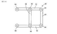
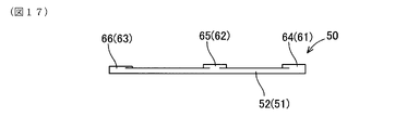
第二分割補強部材50については、図16及び図17を参照して説明する。第二分割補強部材50は、周方向部材51,52と軸方向部材53,54を備える。周方向部材51,52は、長尺状部材によりそれぞれ形成されており、対象物2の周方向に延在する。つまり、周方向部材51,52は、対象物2の外周面における外側凸状の周方向面に沿った形状に形成されている。周方向部材51,52は、対象物2の軸方向に離間している。
第二分割補強部材50の周方向部材51は、吸音シート3を構成する第一分割吸音シート10及び第二分割吸音シート20に跨って、両者の縁部の一部に沿って配置される。詳細には、周方向部材51は、第一分割吸音シート10の第一シート本体11の表面上の縁部の一部、及び、第二分割吸音シート20の第二シート本体21の表面上の縁部の一部に重ねて配置される。
もう1つの周方向部材52は、第一分割吸音シート10の縁部のうち、周方向部材51が配置される第一分割吸音シート10の縁部に対向する縁部、及び、第二分割吸音シート20の縁部のうち、周方向部材51が配置される第二分割吸音シート20の縁部に対向する縁部に配置される。つまり、周方向部材52も、吸音シート3を構成する第一分割吸音シート10及び第二分割吸音シート20に跨って、両者の縁部の一部に沿って配置される。
周方向部材51,52は、第一分割吸音シート10及び第二分割吸音シート20の縁部において、対象物2の軸方向に対向する異なる位置に配置される。このように、周方向部材51,52は、第一分割吸音シート10及び第二分割吸音シート20の面方向に離れて配置される。そして、周方向部材52は、第一分割吸音シート10の第一シート本体11の表面上の縁部の一部、及び、第二分割吸音シート20の第二シート本体21の表面上の縁部の一部に重ねて配置される。
第二分割補強部材50の軸方向部材53は、長尺状部材により形成されており、周方向部材51,52の一端同士を接続する。軸方向部材53は、対象物2の軸方向に延在する。つまり、軸方向部材53は、周方向部材51,52のそれぞれに対して結合されて配置されている。このように、軸方向部材53は、第二分割吸音シート20の縁部の一部に沿って配置される。詳細には、軸方向部材53は、第二分割吸音シート20の第二シート本体21の表面上の縁部の一部に重ねて配置される。なお、軸方向部材53と周方向部材51,52のそれぞれとは、端部同士が結合されているが、十字状等のように交差するように配置しても良い。
第二分割補強部材50の軸方向部材54は、長尺状部材により形成されており、周方向部材51,52の長尺方向の中間部同士を接続する。軸方向部材54は、対象物2の軸方向に延在する。つまり、軸方向部材54は、周方向部材51,52のそれぞれに対して結合されて配置されている。また、軸方向部材54は、第二分割吸音シート20の第二シート本体21の表面上の一部に重ねて配置される。なお、軸方向部材54と周方向部材51,52のそれぞれとは、端部同士が結合されているが、十字状等のように交差するように配置しても良い。
さらに、第二分割補強部材50を構成する周方向部材51は、軸方向部材53と結合する部位、すなわち長尺方向の一端に、係合部61を備える。周方向部材51は、軸方向部材54と結合する部位、すなわち長尺方向の中間部に、係合部62を備える。係合部61,62は、例えば、円筒状の座面を形成しており、対象物2の被係合部2d,2c(ボルト螺合穴、第一被係合部)に係合する位置に配置される。本例では、係合部61,62は、係合部材6d,6c(図2に示す)としてのボルトを挿通する穴を有しており、係合部材6d,6cによって、対象物2の被係合部2d,2cに位置決めされる。なお、係合部61,62は、対象物2の被係合部2d,2cに対して、爪等により直接係止される構成を有しても良い。
さらに、周方向部材51は、長尺方向の他端に、係合部63を備える。係合部63は、例えば、円筒状の座面を形成しており、対象物2の被係合部2b(ボルト螺合穴、第一被係合部)に係合する位置に配置される。係合部63は、第一分割補強部材30の係合部42に重ねて配置される。そして、本例では、係合部63は、係合部材6b(図2に示す)としてのボルトを挿通する穴を有しており、係合部材6bによって、係合部42と共に対象物2の被係合部2bに位置決めされる。
第二分割補強部材50を構成する周方向部材52は、軸方向部材53と結合する部位、すなわち長尺方向の一端に、係合部64を備える。周方向部材52は、軸方向部材54と結合する部位、すなわち長尺方向の中間部に、係合部65を備える。係合部64,65は、例えば、円筒状の座面を形成しており、対象物2の被係合部2h,2g(ボルト螺合穴、第二被係合部)に係合する位置に配置される。本例では、係合部64,65は、係合部材6h,6g(図2に示す)としてのボルトを挿通する穴を有しており、係合部材6h,6gによって、対象物2の被係合部2h,2gに位置決めされる。なお、係合部64,65は、対象物2の被係合部2h,2gに対して、爪等により直接係止される構成を有しても良い。
さらに、周方向部材52は、長尺方向の他端に、係合部66を備える。係合部66は、例えば、円筒状の座面を形成しており、対象物2の被係合部2f(ボルト螺合穴、第二被係合部)に係合する位置に配置される。係合部66は、第一分割補強部材30の係合部44に重ねて配置される。そして、本例では、係合部66は、係合部材6f(図2に示す)としてのボルトを挿通する穴を有しており、係合部材6fによって、係合部44と共に対象物2の被係合部2fに位置決めされる。
上述したように、吸音シート3を複数の分割体10,20により構成し、補強部材4を複数の分割体30,50により構成している。これにより、対象物2の全周を被覆する構成とした場合に、防音カバー1を対象物2に容易に取り付けることができる。
また、吸音シート3を複数の分割体10,20により構成した場合において、第二分割補強部材50の周方向部材51,52が複数の分割体10,20に跨って配置するようにした。これにより、吸音シート3を構成する複数の分割体10,20を確実に位置決めすることができる。
(3.他の例)
上記の例においては、補強部材4が、吸音シート3と別体に形成され、吸音シート3の表面上に配置されることにより、補強部材4と対象物2との間に吸音シート3を挟んで配置されるようにした。
上記の例においては、補強部材4が、吸音シート3と別体に形成され、吸音シート3の表面上に配置されることにより、補強部材4と対象物2との間に吸音シート3を挟んで配置されるようにした。
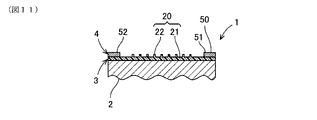
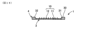
この他に、図18に示すように、補強部材4は、吸音シート3の周面(面方向の端面)に一体化される。この場合、補強部材4は、吸音シート3を介在することなく、対象物2に固定される。補強部材4が対象物2に固定されることにより、補強部材4に一体化されている吸音シート3が対象物2に対して位置決めされる。
例えば、第一分割補強部材30を構成する周方向部材31,32及び軸方向部材33が、第一分割吸音シート10の周面のうち隣接する位置に一体化される。第二分割補強部材50を構成する周方向部材51,52及び軸方向部材53が、第二分割吸音シート20の周面のうち隣接する位置に一体化される。
また、第二分割補強部材50を構成する軸方向部材54は、第二分割吸音シート20の表面上に一体化されるようにしても良い。この他に、吸音シート3をさらに分割することにより、第二分割補強部材50を構成する軸方向部材54も、分割された吸音シート3の周面に一体化されるようにしても良い。
なお、図18においては、補強部材4を構成するそれぞれの長尺状部材(31,32,33,51,52,53,54)が、吸音シート3の周面に一体化されるようにした。この他に、補強部材4を構成するそれぞれの長尺状部材(31,32,33,51,52,53,54)が、吸音シート3の表面上に一体化されるようにしても良い。
Claims (30)
- 対象物(2)を被覆する防音カバー(1)であって、
吸音材により面状に形成され、前記対象物の表面を被覆する吸音シート(3)と、
前記対象物の被係合部(2a,2b,2c,2d,2e,2f,2g,2h)に係合する位置に配置され、前記吸音シートの少なくとも一部を露出させた状態で前記吸音シートを前記対象物に対して位置決めする補強部材(4)と、
を備え、
前記補強部材は、
長尺状部材であり、前記対象物の第一被係合部(2a,2b,2c,2d)に係合する位置に配置される第一補強部(31,51)と、
長尺状部材であり、前記第一補強部とは異なる位置に配置される第二補強部(32,33,52,53,54)と、
を備える、防音カバー(1)。 - 前記第二補強部(32,33,52,53,54)は、前記対象物の前記第一被係合部(2a,2b,2c,2d)とは異なる第二被係合部(2e,2f,2g,2h)に係合する位置に配置される、請求項1に記載の防音カバー。
- 前記補強部材は、前記吸音シートに別体に形成され又は一体化され、前記吸音シートの表面上に配置されることにより、前記補強部材と前記対象物との間に前記吸音シートを挟んで配置される、請求項1又は2に記載の防音カバー。
- 前記第一補強部(31,51)及び前記第二補強部(32,52)は、前記吸音シートの表面上において前記吸音シートの面方向に離れて配置される、請求項3に記載の防音カバー。
- 前記第一補強部(31,51)及び前記第二補強部(32,52)は、前記吸音シートの表面上において、前記吸音シートの縁部における異なる位置に配置される、請求項4に記載の防音カバー。
- 前記第一補強部(31,51)及び前記第二補強部(33,53,54)は、前記吸音シートの表面上において結合されて配置される、請求項3に記載の防音カバー。
- 前記補強部材は、前記吸音シートの周面に一体化される、請求項1又は2に記載の防音カバー。
- 前記第一補強部は、前記吸音シートの周面のうちの第一位置に一体化され、
前記第二補強部は、前記吸音シートの周面のうち前記第一位置に対向する位置に一体化される、請求項7に記載の防音カバー。 - 前記第一補強部(31,51)は、前記吸音シートの周面のうち第一位置に一体化され、
前記第二補強部(33,53)は、前記第一補強部に一体化され、前記吸音シートの周面のうち前記第一位置に隣接する位置に一体化される、請求項7に記載の防音カバー。 - 前記吸音シートは、別体に形成された複数の分割体(10,20)を備え、
前記第一補強部(31,51)及び前記第二補強部(32,52)の少なくとも一方は、前記複数の分割体に跨って配置される、請求項1-9の何れか1項に記載の防音カバー。 - 前記対象物の表面は、外側に凸となる湾曲面を有し、
前記第一補強部(31,51)及び前記第二補強部(32,52)の少なくとも一方は、長尺状における一端側から他端側に向かって外側に凸となる湾曲した形状に形成され、前記対象物の前記湾曲面に沿って配置される、請求項1-10の何れか1項に記載の防音カバー。 - 前記吸音シートは、発泡樹脂により形成され、
前記補強部材は、前記吸音シートとは異なる発泡樹脂により形成される、請求項1-11の何れか1項に記載の防音カバー。 - 前記補強部材の発泡樹脂のアスカーC硬度は、60~99度である、請求項12に記載の防音カバー。
- 前記吸音シートの発泡樹脂のアスカーC硬度は、1~60度である、請求項13に記載の防音カバー。
- 前記吸音シートの表層は、発泡樹脂のセルが閉じたクローズドセル状態とされる、請求項12-14の何れか1項に記載の防音カバー。
- 前記吸音シートの裏層は、発泡樹脂のセルが開いたオープンセル状態とされる、請求項15に記載の防音カバー。
- 前記吸音シートは、発泡樹脂により形成され、
前記補強部材は、前記発泡樹脂よりも硬度の高いゴム、樹脂又は金属により形成される、請求項1-11の何れか1項に記載の防音カバー。 - 前記防音カバーは、さらに、
前記補強部材に固定され、前記吸音シートの表面に沿って対向して配置され、前記吸音シートの表面との間において流体の流通をガイドする通風ガイド(5)を備える、請求項1-17の何れか1項に記載の防音カバー。 - 前記通風ガイドは、前記補強部材と同一材料により形成される、請求項18に記載の防音カバー。
- 前記通風ガイドは、前記補強部材とは剛性の異なる材料により形成される、請求項18に記載の防音カバー。
- 前記対象物は、車両の動力源であり、
前記通風ガイドは、前記対象物における前記車両の前後方向の後方面に対向して配置され、前記車両の前方から後方に向かって流通する流体を前記対象物における前記後方面へガイドする、請求項18-20の何れか1項に記載の防音カバー。 - 前記補強部材は、さらに、
長尺状部材であり、前記第一補強部(31,51)及び前記第二補強部(32,52)とは異なる位置に配置される第三補強部(33)を備える、請求項1-21の何れか1項に記載の防音カバー。 - 前記補強部材は、さらに、
長尺状部材であり、前記第一補強部、前記第二補強部及び前記第三補強部とは異なる位置に配置される第四補強部(53)を備える、請求項22に記載の防音カバー。 - 前記第一補強部(31,51)、前記第二補強部(32,52)、前記第三補強部(33)及び前記第四補強部(53)は、矩形のそれぞれの一辺とする矩形枠部材を構成する、請求項23に記載の防音カバー。
- 前記吸音シートは、表面に、複数の放熱フィン(12,22,23)を備える、請求項1-24の何れか1項に記載の防音カバー。
- 前記吸音シートは、別体に形成され、前記複数の放熱フィン(12,22,23)をそれぞれ備える複数の分割体(10,20)を備え、
隣り合う前記複数の分割体(10,20)における前記放熱フィン(12,23)は、連続して配置される、請求項25に記載の防音カバー。 - 前記吸音シートは、熱伝導材を含む発泡樹脂により形成され、
前記熱伝導材は、前記吸音シートの裏面から前記放熱フィンの先端において、前記吸音シートの面法線方向に連続して延在されている、請求項25又は26に記載の防音カバー。 - 前記放熱フィンは、前記吸音シートの面方向に延在し、
前記吸音シートは、第二熱伝導材を含む発泡樹脂により形成され、
前記第二熱伝導材は、前記吸音シートの前記放熱フィンの先端側において、当該放熱フィンの延在方向に沿って延在されている、請求項25-27の何れか1項に記載の防音カバー。 - 前記吸音シートは、熱伝導材を含む発泡樹脂により形成され、
前記熱伝導材は、前記吸音シートの裏面から表面に向かって延在されている、請求項1-28の何れか1項に記載の防音カバー。 - 前記熱伝導材は、熱伝導フィラーであり、前記吸音シートの裏面から表面に向かって配列されており、
前記熱伝導材の充填量は、前記吸音シートの位置によって異なる、請求項29に記載の防音カバー。
Priority Applications (3)
| Application Number | Priority Date | Filing Date | Title |
|---|---|---|---|
| EP21903217.4A EP4223994B1 (en) | 2020-12-07 | 2021-11-29 | Soundproof cover |
| CN202180075448.8A CN116420186A (zh) | 2020-12-07 | 2021-11-29 | 隔音罩 |
| US18/314,093 US20230272740A1 (en) | 2020-12-07 | 2023-05-08 | Soundproof cover |
Applications Claiming Priority (2)
| Application Number | Priority Date | Filing Date | Title |
|---|---|---|---|
| JP2020-203034 | 2020-12-07 | ||
| JP2020203034A JP7174747B2 (ja) | 2020-12-07 | 2020-12-07 | 防音カバー |
Related Child Applications (1)
| Application Number | Title | Priority Date | Filing Date |
|---|---|---|---|
| US18/314,093 Continuation US20230272740A1 (en) | 2020-12-07 | 2023-05-08 | Soundproof cover |
Publications (1)
| Publication Number | Publication Date |
|---|---|
| WO2022124113A1 true WO2022124113A1 (ja) | 2022-06-16 |
Family
ID=81973932
Family Applications (1)
| Application Number | Title | Priority Date | Filing Date |
|---|---|---|---|
| PCT/JP2021/043622 Ceased WO2022124113A1 (ja) | 2020-12-07 | 2021-11-29 | 防音カバー |
Country Status (5)
| Country | Link |
|---|---|
| US (1) | US20230272740A1 (ja) |
| EP (1) | EP4223994B1 (ja) |
| JP (1) | JP7174747B2 (ja) |
| CN (1) | CN116420186A (ja) |
| WO (1) | WO2022124113A1 (ja) |
Cited By (1)
| Publication number | Priority date | Publication date | Assignee | Title |
|---|---|---|---|---|
| WO2024096096A1 (ja) | 2022-11-04 | 2024-05-10 | 住友理工株式会社 | 防音放熱カバー |
Families Citing this family (3)
| Publication number | Priority date | Publication date | Assignee | Title |
|---|---|---|---|---|
| JP7576734B1 (ja) * | 2023-04-27 | 2024-10-31 | 住友理工株式会社 | 防音放熱カバー、カバー部材、および防音放熱カバーの製造方法 |
| WO2024225341A1 (ja) * | 2023-04-27 | 2024-10-31 | 住友理工株式会社 | 防音放熱カバー、カバー部材、および防音放熱カバーの製造方法 |
| DE102023136214A1 (de) * | 2023-12-21 | 2025-06-26 | Audi Aktiengesellschaft | Temperaturabhängiges Dämpfen von Schwingungen |
Citations (16)
| Publication number | Priority date | Publication date | Assignee | Title |
|---|---|---|---|---|
| JPS5688927U (ja) * | 1979-12-12 | 1981-07-16 | ||
| JPS5768141U (ja) * | 1980-10-11 | 1982-04-23 | ||
| JPS6338615U (ja) * | 1986-08-29 | 1988-03-12 | ||
| JPH0572597U (ja) * | 1992-03-09 | 1993-10-05 | 河西工業株式会社 | エンジンルーム用インシュレータ |
| JPH09151788A (ja) | 1995-11-29 | 1997-06-10 | Aisin Seiki Co Ltd | 防音カバー |
| JP2000230431A (ja) * | 1999-02-09 | 2000-08-22 | Tokai Rubber Ind Ltd | 防音カバー |
| JP2006183571A (ja) | 2004-12-27 | 2006-07-13 | Toyoda Gosei Co Ltd | エンジンカバーの取付構造 |
| JP2006257993A (ja) * | 2005-03-17 | 2006-09-28 | Tokai Rubber Ind Ltd | 防音カバー |
| JP2008289260A (ja) * | 2007-05-16 | 2008-11-27 | Nsk Ltd | 回転電機及び電動パワーステアリング装置 |
| JP2010126677A (ja) * | 2008-11-28 | 2010-06-10 | Tokai Rubber Ind Ltd | ウレタン発泡成形体およびその製造方法 |
| JP2012040912A (ja) | 2010-08-17 | 2012-03-01 | Pacific Ind Co Ltd | エンジンカバー |
| JP2015037916A (ja) * | 2013-08-19 | 2015-02-26 | 日本精工株式会社 | 電動パワーステアリング装置 |
| JP2017181968A (ja) | 2016-03-31 | 2017-10-05 | 住友理工株式会社 | 防音カバー |
| JP2018070147A (ja) * | 2016-10-24 | 2018-05-10 | ハンコック タイヤ カンパニー リミテッド | 共鳴音低減タイヤ及びその製造方法 |
| JP2019043498A (ja) | 2017-09-07 | 2019-03-22 | トヨタ自動車株式会社 | エンジンカバー |
| JP2019086551A (ja) * | 2017-11-01 | 2019-06-06 | 王子ホールディングス株式会社 | 吸音材 |
Family Cites Families (2)
| Publication number | Priority date | Publication date | Assignee | Title |
|---|---|---|---|---|
| JP5530880B2 (ja) * | 2010-09-28 | 2014-06-25 | 東海ゴム工業株式会社 | 管体用防音カバーおよびカバー付き管体 |
| CN106183347B (zh) * | 2016-08-10 | 2018-07-13 | 广德天运新技术股份有限公司 | 一种隔热隔音减震纤维毡的制备方法 |
-
2020
- 2020-12-07 JP JP2020203034A patent/JP7174747B2/ja active Active
-
2021
- 2021-11-29 EP EP21903217.4A patent/EP4223994B1/en active Active
- 2021-11-29 WO PCT/JP2021/043622 patent/WO2022124113A1/ja not_active Ceased
- 2021-11-29 CN CN202180075448.8A patent/CN116420186A/zh active Pending
-
2023
- 2023-05-08 US US18/314,093 patent/US20230272740A1/en active Pending
Patent Citations (16)
| Publication number | Priority date | Publication date | Assignee | Title |
|---|---|---|---|---|
| JPS5688927U (ja) * | 1979-12-12 | 1981-07-16 | ||
| JPS5768141U (ja) * | 1980-10-11 | 1982-04-23 | ||
| JPS6338615U (ja) * | 1986-08-29 | 1988-03-12 | ||
| JPH0572597U (ja) * | 1992-03-09 | 1993-10-05 | 河西工業株式会社 | エンジンルーム用インシュレータ |
| JPH09151788A (ja) | 1995-11-29 | 1997-06-10 | Aisin Seiki Co Ltd | 防音カバー |
| JP2000230431A (ja) * | 1999-02-09 | 2000-08-22 | Tokai Rubber Ind Ltd | 防音カバー |
| JP2006183571A (ja) | 2004-12-27 | 2006-07-13 | Toyoda Gosei Co Ltd | エンジンカバーの取付構造 |
| JP2006257993A (ja) * | 2005-03-17 | 2006-09-28 | Tokai Rubber Ind Ltd | 防音カバー |
| JP2008289260A (ja) * | 2007-05-16 | 2008-11-27 | Nsk Ltd | 回転電機及び電動パワーステアリング装置 |
| JP2010126677A (ja) * | 2008-11-28 | 2010-06-10 | Tokai Rubber Ind Ltd | ウレタン発泡成形体およびその製造方法 |
| JP2012040912A (ja) | 2010-08-17 | 2012-03-01 | Pacific Ind Co Ltd | エンジンカバー |
| JP2015037916A (ja) * | 2013-08-19 | 2015-02-26 | 日本精工株式会社 | 電動パワーステアリング装置 |
| JP2017181968A (ja) | 2016-03-31 | 2017-10-05 | 住友理工株式会社 | 防音カバー |
| JP2018070147A (ja) * | 2016-10-24 | 2018-05-10 | ハンコック タイヤ カンパニー リミテッド | 共鳴音低減タイヤ及びその製造方法 |
| JP2019043498A (ja) | 2017-09-07 | 2019-03-22 | トヨタ自動車株式会社 | エンジンカバー |
| JP2019086551A (ja) * | 2017-11-01 | 2019-06-06 | 王子ホールディングス株式会社 | 吸音材 |
Non-Patent Citations (1)
| Title |
|---|
| See also references of EP4223994A4 |
Cited By (4)
| Publication number | Priority date | Publication date | Assignee | Title |
|---|---|---|---|---|
| WO2024096096A1 (ja) | 2022-11-04 | 2024-05-10 | 住友理工株式会社 | 防音放熱カバー |
| JP2024067353A (ja) * | 2022-11-04 | 2024-05-17 | 住友理工株式会社 | 防音放熱カバー |
| JP7576600B2 (ja) | 2022-11-04 | 2024-10-31 | 住友理工株式会社 | 防音放熱カバー |
| EP4550307A4 (en) * | 2022-11-04 | 2025-10-08 | Sumitomo Riko Co Ltd | SOUNDPROOF HEAT DISSIPATION COVER |
Also Published As
| Publication number | Publication date |
|---|---|
| CN116420186A (zh) | 2023-07-11 |
| EP4223994A4 (en) | 2024-04-03 |
| EP4223994A1 (en) | 2023-08-09 |
| JP2022090561A (ja) | 2022-06-17 |
| JP7174747B2 (ja) | 2022-11-17 |
| EP4223994B1 (en) | 2025-01-29 |
| US20230272740A1 (en) | 2023-08-31 |
Similar Documents
| Publication | Publication Date | Title |
|---|---|---|
| WO2022124113A1 (ja) | 防音カバー | |
| US20220320659A1 (en) | Hybrid energy-absorption for vehicle battery pack frames | |
| EP1714856B1 (en) | Frp panel for automobile | |
| US20030192727A1 (en) | Structure of front portion of vehicle body | |
| CN110021722B (zh) | 具有电池保护装置的电动车辆及相应的方法 | |
| JP2022090561A5 (ja) | ||
| US7753435B2 (en) | Water shield for vehicle door | |
| CN107074299B (zh) | 包括支撑结构和声部件的舱壁 | |
| JP2005067445A (ja) | 車両のサイドシル | |
| JP5030657B2 (ja) | 車両用エアガイド構造 | |
| JP2018047857A (ja) | グローブボックス | |
| JP7576600B2 (ja) | 防音放熱カバー | |
| JP2009012560A (ja) | 自動車用内装部品 | |
| JP2004156871A (ja) | 薄型流路形成体その製造方法 | |
| JP5555438B2 (ja) | 自動車用ウエザーストリップ | |
| JP7266002B2 (ja) | 組み付け構造体 | |
| CN222774863U (zh) | 保护壳和数据保护装置 | |
| JP2006224840A (ja) | 操作具案内溝のシール構造 | |
| EP3967530B1 (en) | Vehicle air conditioning device hot water pipe holding structure | |
| JP4925450B2 (ja) | 自動車用内装部品 | |
| US20250095620A1 (en) | Soundproof heat-dissipation cover, cover member, and manufacturing method of soundproof heat dissipation cover | |
| JP5021401B2 (ja) | ルーフ衝撃吸収構造 | |
| JP6345388B2 (ja) | 内装部品合わせ構造 | |
| KR20200074463A (ko) | 시트백 및 이의 제조 방법 | |
| JP2006182067A (ja) | 車両用放熱装置および車両用内装部品の放熱方法 |
Legal Events
| Date | Code | Title | Description |
|---|---|---|---|
| 121 | Ep: the epo has been informed by wipo that ep was designated in this application |
Ref document number: 21903217 Country of ref document: EP Kind code of ref document: A1 |
|
| ENP | Entry into the national phase |
Ref document number: 2021903217 Country of ref document: EP Effective date: 20230503 |
|
| NENP | Non-entry into the national phase |
Ref country code: DE |