WO2022123920A1 - 光照射医療装置 - Google Patents
光照射医療装置 Download PDFInfo
- Publication number
- WO2022123920A1 WO2022123920A1 PCT/JP2021/038881 JP2021038881W WO2022123920A1 WO 2022123920 A1 WO2022123920 A1 WO 2022123920A1 JP 2021038881 W JP2021038881 W JP 2021038881W WO 2022123920 A1 WO2022123920 A1 WO 2022123920A1
- Authority
- WO
- WIPO (PCT)
- Prior art keywords
- shaft
- light
- window
- guide device
- light guide
- Prior art date
- Legal status (The legal status is an assumption and is not a legal conclusion. Google has not performed a legal analysis and makes no representation as to the accuracy of the status listed.)
- Ceased
Links
Images




Classifications
-
- A—HUMAN NECESSITIES
- A61—MEDICAL OR VETERINARY SCIENCE; HYGIENE
- A61N—ELECTROTHERAPY; MAGNETOTHERAPY; RADIATION THERAPY; ULTRASOUND THERAPY
- A61N5/00—Radiation therapy
- A61N5/06—Radiation therapy using light
- A61N5/0601—Apparatus for use inside the body
-
- A—HUMAN NECESSITIES
- A61—MEDICAL OR VETERINARY SCIENCE; HYGIENE
- A61N—ELECTROTHERAPY; MAGNETOTHERAPY; RADIATION THERAPY; ULTRASOUND THERAPY
- A61N5/00—Radiation therapy
- A61N5/06—Radiation therapy using light
- A61N5/0613—Apparatus adapted for a specific treatment
- A61N5/062—Photodynamic therapy, i.e. excitation of an agent
-
- A—HUMAN NECESSITIES
- A61—MEDICAL OR VETERINARY SCIENCE; HYGIENE
- A61B—DIAGNOSIS; SURGERY; IDENTIFICATION
- A61B18/00—Surgical instruments, devices or methods for transferring non-mechanical forms of energy to or from the body
- A61B18/18—Surgical instruments, devices or methods for transferring non-mechanical forms of energy to or from the body by applying electromagnetic radiation, e.g. microwaves
- A61B18/20—Surgical instruments, devices or methods for transferring non-mechanical forms of energy to or from the body by applying electromagnetic radiation, e.g. microwaves using laser
- A61B18/22—Surgical instruments, devices or methods for transferring non-mechanical forms of energy to or from the body by applying electromagnetic radiation, e.g. microwaves using laser the beam being directed along or through a flexible conduit, e.g. an optical fibre; Couplings or hand-pieces therefor
-
- A—HUMAN NECESSITIES
- A61—MEDICAL OR VETERINARY SCIENCE; HYGIENE
- A61B—DIAGNOSIS; SURGERY; IDENTIFICATION
- A61B18/00—Surgical instruments, devices or methods for transferring non-mechanical forms of energy to or from the body
- A61B18/18—Surgical instruments, devices or methods for transferring non-mechanical forms of energy to or from the body by applying electromagnetic radiation, e.g. microwaves
- A61B18/20—Surgical instruments, devices or methods for transferring non-mechanical forms of energy to or from the body by applying electromagnetic radiation, e.g. microwaves using laser
- A61B18/22—Surgical instruments, devices or methods for transferring non-mechanical forms of energy to or from the body by applying electromagnetic radiation, e.g. microwaves using laser the beam being directed along or through a flexible conduit, e.g. an optical fibre; Couplings or hand-pieces therefor
- A61B18/24—Surgical instruments, devices or methods for transferring non-mechanical forms of energy to or from the body by applying electromagnetic radiation, e.g. microwaves using laser the beam being directed along or through a flexible conduit, e.g. an optical fibre; Couplings or hand-pieces therefor with a catheter
-
- A—HUMAN NECESSITIES
- A61—MEDICAL OR VETERINARY SCIENCE; HYGIENE
- A61M—DEVICES FOR INTRODUCING MEDIA INTO, OR ONTO, THE BODY; DEVICES FOR TRANSDUCING BODY MEDIA OR FOR TAKING MEDIA FROM THE BODY; DEVICES FOR PRODUCING OR ENDING SLEEP OR STUPOR
- A61M25/00—Catheters; Hollow probes
- A61M25/10—Balloon catheters
-
- A—HUMAN NECESSITIES
- A61—MEDICAL OR VETERINARY SCIENCE; HYGIENE
- A61N—ELECTROTHERAPY; MAGNETOTHERAPY; RADIATION THERAPY; ULTRASOUND THERAPY
- A61N5/00—Radiation therapy
- A61N5/06—Radiation therapy using light
- A61N5/0601—Apparatus for use inside the body
- A61N5/0603—Apparatus for use inside the body for treatment of body cavities
-
- A—HUMAN NECESSITIES
- A61—MEDICAL OR VETERINARY SCIENCE; HYGIENE
- A61B—DIAGNOSIS; SURGERY; IDENTIFICATION
- A61B18/00—Surgical instruments, devices or methods for transferring non-mechanical forms of energy to or from the body
- A61B2018/00053—Mechanical features of the instrument of device
- A61B2018/00184—Moving parts
- A61B2018/00196—Moving parts reciprocating lengthwise
-
- A—HUMAN NECESSITIES
- A61—MEDICAL OR VETERINARY SCIENCE; HYGIENE
- A61B—DIAGNOSIS; SURGERY; IDENTIFICATION
- A61B18/00—Surgical instruments, devices or methods for transferring non-mechanical forms of energy to or from the body
- A61B2018/00053—Mechanical features of the instrument of device
- A61B2018/00273—Anchoring means for temporary attachment of a device to tissue
-
- A—HUMAN NECESSITIES
- A61—MEDICAL OR VETERINARY SCIENCE; HYGIENE
- A61B—DIAGNOSIS; SURGERY; IDENTIFICATION
- A61B18/00—Surgical instruments, devices or methods for transferring non-mechanical forms of energy to or from the body
- A61B2018/00053—Mechanical features of the instrument of device
- A61B2018/00273—Anchoring means for temporary attachment of a device to tissue
- A61B2018/00279—Anchoring means for temporary attachment of a device to tissue deployable
- A61B2018/00285—Balloons
-
- A—HUMAN NECESSITIES
- A61—MEDICAL OR VETERINARY SCIENCE; HYGIENE
- A61B—DIAGNOSIS; SURGERY; IDENTIFICATION
- A61B18/00—Surgical instruments, devices or methods for transferring non-mechanical forms of energy to or from the body
- A61B2018/00315—Surgical instruments, devices or methods for transferring non-mechanical forms of energy to or from the body for treatment of particular body parts
- A61B2018/00345—Vascular system
- A61B2018/00404—Blood vessels other than those in or around the heart
-
- A—HUMAN NECESSITIES
- A61—MEDICAL OR VETERINARY SCIENCE; HYGIENE
- A61B—DIAGNOSIS; SURGERY; IDENTIFICATION
- A61B18/00—Surgical instruments, devices or methods for transferring non-mechanical forms of energy to or from the body
- A61B2018/00315—Surgical instruments, devices or methods for transferring non-mechanical forms of energy to or from the body for treatment of particular body parts
- A61B2018/00482—Digestive system
-
- A—HUMAN NECESSITIES
- A61—MEDICAL OR VETERINARY SCIENCE; HYGIENE
- A61B—DIAGNOSIS; SURGERY; IDENTIFICATION
- A61B18/00—Surgical instruments, devices or methods for transferring non-mechanical forms of energy to or from the body
- A61B2018/00571—Surgical instruments, devices or methods for transferring non-mechanical forms of energy to or from the body for achieving a particular surgical effect
- A61B2018/00577—Ablation
-
- A—HUMAN NECESSITIES
- A61—MEDICAL OR VETERINARY SCIENCE; HYGIENE
- A61B—DIAGNOSIS; SURGERY; IDENTIFICATION
- A61B18/00—Surgical instruments, devices or methods for transferring non-mechanical forms of energy to or from the body
- A61B2018/00982—Surgical instruments, devices or methods for transferring non-mechanical forms of energy to or from the body combined with or comprising means for visual or photographic inspections inside the body, e.g. endoscopes
-
- A—HUMAN NECESSITIES
- A61—MEDICAL OR VETERINARY SCIENCE; HYGIENE
- A61B—DIAGNOSIS; SURGERY; IDENTIFICATION
- A61B18/00—Surgical instruments, devices or methods for transferring non-mechanical forms of energy to or from the body
- A61B18/18—Surgical instruments, devices or methods for transferring non-mechanical forms of energy to or from the body by applying electromagnetic radiation, e.g. microwaves
- A61B18/20—Surgical instruments, devices or methods for transferring non-mechanical forms of energy to or from the body by applying electromagnetic radiation, e.g. microwaves using laser
- A61B18/22—Surgical instruments, devices or methods for transferring non-mechanical forms of energy to or from the body by applying electromagnetic radiation, e.g. microwaves using laser the beam being directed along or through a flexible conduit, e.g. an optical fibre; Couplings or hand-pieces therefor
- A61B2018/2255—Optical elements at the distal end of probe tips
- A61B2018/2261—Optical elements at the distal end of probe tips with scattering, diffusion or dispersion of light
-
- A—HUMAN NECESSITIES
- A61—MEDICAL OR VETERINARY SCIENCE; HYGIENE
- A61B—DIAGNOSIS; SURGERY; IDENTIFICATION
- A61B18/00—Surgical instruments, devices or methods for transferring non-mechanical forms of energy to or from the body
- A61B18/18—Surgical instruments, devices or methods for transferring non-mechanical forms of energy to or from the body by applying electromagnetic radiation, e.g. microwaves
- A61B18/20—Surgical instruments, devices or methods for transferring non-mechanical forms of energy to or from the body by applying electromagnetic radiation, e.g. microwaves using laser
- A61B18/22—Surgical instruments, devices or methods for transferring non-mechanical forms of energy to or from the body by applying electromagnetic radiation, e.g. microwaves using laser the beam being directed along or through a flexible conduit, e.g. an optical fibre; Couplings or hand-pieces therefor
- A61B2018/2255—Optical elements at the distal end of probe tips
- A61B2018/2266—Optical elements at the distal end of probe tips with a lens, e.g. ball tipped
-
- A—HUMAN NECESSITIES
- A61—MEDICAL OR VETERINARY SCIENCE; HYGIENE
- A61B—DIAGNOSIS; SURGERY; IDENTIFICATION
- A61B18/00—Surgical instruments, devices or methods for transferring non-mechanical forms of energy to or from the body
- A61B18/18—Surgical instruments, devices or methods for transferring non-mechanical forms of energy to or from the body by applying electromagnetic radiation, e.g. microwaves
- A61B18/20—Surgical instruments, devices or methods for transferring non-mechanical forms of energy to or from the body by applying electromagnetic radiation, e.g. microwaves using laser
- A61B18/22—Surgical instruments, devices or methods for transferring non-mechanical forms of energy to or from the body by applying electromagnetic radiation, e.g. microwaves using laser the beam being directed along or through a flexible conduit, e.g. an optical fibre; Couplings or hand-pieces therefor
- A61B2018/2255—Optical elements at the distal end of probe tips
- A61B2018/2272—Optical elements at the distal end of probe tips with reflective or refractive surfaces for deflecting the beam
-
- A—HUMAN NECESSITIES
- A61—MEDICAL OR VETERINARY SCIENCE; HYGIENE
- A61N—ELECTROTHERAPY; MAGNETOTHERAPY; RADIATION THERAPY; ULTRASOUND THERAPY
- A61N5/00—Radiation therapy
- A61N5/06—Radiation therapy using light
- A61N5/0601—Apparatus for use inside the body
- A61N2005/0602—Apparatus for use inside the body for treatment of blood vessels
-
- A—HUMAN NECESSITIES
- A61—MEDICAL OR VETERINARY SCIENCE; HYGIENE
- A61N—ELECTROTHERAPY; MAGNETOTHERAPY; RADIATION THERAPY; ULTRASOUND THERAPY
- A61N5/00—Radiation therapy
- A61N5/06—Radiation therapy using light
- A61N2005/063—Radiation therapy using light comprising light transmitting means, e.g. optical fibres
-
- A—HUMAN NECESSITIES
- A61—MEDICAL OR VETERINARY SCIENCE; HYGIENE
- A61N—ELECTROTHERAPY; MAGNETOTHERAPY; RADIATION THERAPY; ULTRASOUND THERAPY
- A61N5/00—Radiation therapy
- A61N5/06—Radiation therapy using light
- A61N2005/0664—Details
- A61N2005/0665—Reflectors
Definitions
- the present invention relates to a light irradiation medical device for irradiating tissues such as cancer cells with light in internal lumens such as blood vessels and gastrointestinal tracts.
- a photosensitizer is administered into the body by intravenous injection or intraperitoneal administration, and the photosensitizer is accumulated in the target tissue such as cancer cells, resulting in light of a specific wavelength.
- the photosensitizer is excited by irradiating with. When the excited photosensitizer returns to the ground state, energy transformation occurs, generating reactive oxygen species.
- the target tissue can be removed by the active oxygen species attacking the target tissue.
- ablation using laser light the target tissue is irradiated with laser light and cauterized. A device for performing such light irradiation has been proposed.
- Patent Document 1 discloses an endoscope system having an insertion unit, an illumination light irradiation unit, a treatment light irradiation unit, and a light receiving unit.
- the insertion portion is formed to have a tubular shape that can be inserted into the body cavity of the subject.
- the treatment light irradiation unit is configured to simultaneously irradiate the treatment light into a substantially tubular region laterally or anteriorly to the tip portion.
- Patent Document 2 discloses an optical probe having a tubular probe outer cylinder, an optical waveguide member, a first irradiation unit, and a second irradiation unit.
- the optical waveguide member guides the first light and the second light disposed in the axial direction of the probe outer cylinder in the inner space of the probe outer cylinder.
- the first irradiation unit and the second irradiation unit receive the first light and the second light at different parts on the irradiation target. Irradiate each.
- an object of the present invention is to provide a light irradiation medical device that contributes to the efficiency of the procedure.
- the light guide device comprises a shaft having a light beam and a light guide device arranged in the cavity of the shaft and movable in the longitudinal axis direction of the shaft, the light guide device extending in the longitudinal axis direction of the shaft, and the light guide device. It has a light diffuser at its distal portion, and the shaft has a first window provided on the peripheral wall of the distal portion and a second window provided on the distal end face of the shaft.
- the gist is that the shaft has a reflective surface that reflects the light emitted from the light guide device on the distal side of the first window and inside the shaft.
- the light irradiation direction can be switched by moving the light guide device in the longitudinal axis direction of the shaft. Since it is no longer necessary to replace the device for switching the irradiation direction, it can contribute to the efficiency of the procedure. For example, when the light guide device is moved so that the light diffusing portion overlaps with the first window, the light emitted from the light guide device passes through the first window, and the light guide device is set so that the light diffusing portion overlaps with the reflecting surface. When moved, it is preferable that the light emitted from the light guide device passes through the second window.
- the first window may be longer than the light diffusing part in the longitudinal axis direction of the shaft.
- the first window may be arranged in the entire circumferential direction of the shaft.
- a transparent member that transmits light emitted from the light guide device may be arranged in the first window.
- the reflective surface may be arranged in a longer range than the light diffusing portion in the longitudinal axis direction of the shaft.
- the reflecting surface may be arranged in the entire circumferential direction of the shaft.
- the shaft has a reduced diameter portion in which the inner diameter of the shaft becomes smaller toward the first window side on the distal side of the first window, and a reflective surface may be arranged on the reduced diameter portion.
- the reflective surface may be arranged over the entire section of the shaft on the distal side of the proximal end of the reduced diameter portion.
- the shaft has an inner diameter smaller than the minimum inner diameter of the shaft in the section where the first window is located on the distal side of the first window, and the light guide device can move in the longitudinal axis direction of the shaft. It may have a small diameter portion that comes into contact with it.
- a lens that focuses the light emitted from the light guide device may be provided at the distal end of the lumen of the shaft.
- the light guide device may have a position display unit at its proximal end indicating the position of the light guide device with respect to the shaft.
- the distal portion of the shaft may be provided with an expansion portion that expands outward in the radial direction of the shaft.
- the extension may be a balloon, a basket with multiple elastic wires, or a self-expandable stent.
- the light irradiation direction can be switched by moving the light guide device in the longitudinal axis direction of the shaft. Since it is no longer necessary to replace the device for switching the irradiation direction, it can contribute to the efficiency of the procedure.
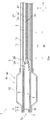
- FIG. 3 is an enlarged cross-sectional view of the distal side of the light irradiation medical device shown in FIG. 1.
- FIG. 3 is a sectional view taken along line III-III of the light irradiation medical device shown in FIG.
- FIG. 6 is a sectional view taken along line IV-IV of the light irradiation medical device shown in FIG.
- It is a VV cross-sectional view of the light irradiation medical apparatus shown in FIG.
- FIG. 3 is an enlarged cross-sectional view of the distal side of the light irradiation medical device shown in FIG. 1.
- One embodiment of the light irradiation medical device of the present invention is a shaft having a first end and a second end in the longitudinal axis direction, the shaft having a lumen extending in the longitudinal axis direction, and the shaft. It comprises a light guide device located in the lumen and movable in the longitudinal axis direction of the shaft, the light guide device extends in the longitudinal axis direction of the shaft, and the light guide device diffuses light to its distal portion.
- the shaft has a first window provided on the peripheral wall of the distal portion thereof and a second window provided on the distal end surface of the shaft, and the shaft has a portion from the first window.
- the light irradiation direction can be switched by moving the light guide device in the longitudinal axis direction of the shaft. Since it is no longer necessary to replace the device for switching the irradiation direction, it can contribute to the efficiency of the procedure.
- the light irradiation medical device is used in PDT and optical ablation to irradiate a treated portion, which is a target tissue such as a cancer cell, with light of a specific wavelength in an internal lumen such as a blood vessel or a digestive tract.
- the light irradiation medical device may be delivered to the treatment unit alone, or may be used together with a delivery catheter or an endoscope.
- endoscopic treatment a light-irradiated medical device is placed in the body through the forceps channel of the endoscope and delivered to the treatment site.
- FIG. 1 is a side view of a light irradiation medical device according to an embodiment of the present invention.
- 2 and 6 are enlarged cross-sectional views of the distal side of the light irradiation medical device shown in FIG.
- FIG. 3 is a sectional view taken along line III-III of the light irradiation medical device shown in FIG.
- FIG. 4 is an IV-IV cross-sectional view of the light irradiation medical device shown in FIG.
- FIG. 5 is a VV cross-sectional view of the light irradiation medical device shown in FIG. FIG.
- the light irradiation medical device 1 includes a shaft 2 and a light guide device 20.
- the light irradiation medical device 1 may be simply referred to as a device 1.
- the distal side of the device 1 refers to the first end side of the shaft 2 in the longitudinal axis direction x and the treatment target side.
- the proximal side of the device 1 is the second end side of the shaft 2 in the longitudinal axis direction x and refers to the user's hand side.
- the proximal side may be referred to as a proximal portion and the distal side may be referred to as a distal portion.
- the shaft 2 has a longitudinal axis direction x, a radial direction y, and a circumferential direction p.
- the shaft 2 has a first end and a second end in the longitudinal axis direction x, and has a lumen 5 extending in the longitudinal axis direction x.
- the first end may correspond to the distal end of the shaft 2 and the second end may correspond to the proximal end of the shaft 2.
- the shaft 2 has a tubular shape. Since the shaft 2 is inserted into the body, it preferably has flexibility.
- the inner side refers to the direction toward the center of the longitudinal axis of the shaft 2
- the outer side refers to the radial direction in the direction opposite to the inner side.
- the shaft 2 is a hollow body formed by arranging one or a plurality of wires in a predetermined pattern; at least one of the inner surface or the outer surface of the hollow body coated with resin; a resin tube; or these. For example, a combination of these, for example, those connected in the longitudinal axis direction x can be mentioned.
- a tubular body having a mesh structure by simply crossing or braiding the wire rods, or a coil in which the wire rods are wound is shown.
- the wire may be one or more single wires, or may be one or more stranded wires.
- the resin tube can be manufactured, for example, by extrusion molding.
- the shaft 2 When the shaft 2 is a resin tube, the shaft 2 can be composed of a single layer or a plurality of layers. A part of the shaft 2 in the longitudinal direction x or the circumferential direction p may be composed of a single layer, and the other portion may be composed of a plurality of layers.
- the shaft 2 may have a long cylindrical main body 3 and a reflective member 4 arranged inside the main body 3.
- a handle 10 gripped by an operator is preferably connected to the proximal portion of the shaft 2.
- the device 1 may be incorporated in an endoscope or may be used as a combined device.
- the shaft 2 is, for example, a polyolefin resin (for example, polyethylene or polypropylene), a polyamide resin (for example, nylon), a polyester resin (for example, PET), an aromatic polyether ketone resin (for example, PEEK), a polyether polyamide resin, or a polyurethane. It can be composed of a synthetic resin such as a resin, a polyimide resin, a fluororesin (for example, PTFE, PFA, ETFE), or a metal such as stainless steel, carbon steel, or nickel-titanium alloy. These may be used alone or in combination of two or more.
- the main body 3 of the shaft 2 is preferably made of any of the above synthetic resins.
- a first window 11 is provided on the peripheral wall 6 at the distal portion of the shaft 2. Further, a second window 12 is provided on the distal end surface 7 of the shaft 2.
- the shaft 2 has a reflecting surface 8 that is distal to the first window 11 and reflects the light emitted from the light guide device 20 inside the shaft 2. According to the device 1, the irradiation direction of the light 50 can be switched by moving the light guide device 20 in the longitudinal axis direction x. Since it is no longer necessary to replace the device for switching the irradiation direction, it can contribute to the efficiency of the procedure.
- the light guide device 20 when the light guide device 20 is moved so that the light diffusion unit 21 overlaps with the first window 11, the light 50 emitted from the light guide device 20 may pass through the first window 11. As a result, the light 50 can be irradiated laterally through the first window 11. As shown in FIG. 6, when the light guide device 20 is moved so that the light diffusion unit 21 overlaps the reflection surface 8, the light 50 emitted from the light guide device 20 may pass through the second window 12. As a result, the light 50 can be emitted forward or distally through the second window 12.
- the light guide device 20 When irradiating laterally, it is preferable to move the light guide device 20 so that the light diffusing portion 21 and the first window 11 overlap at least a part of the longitudinal axis direction x. When irradiating forward, it is preferable to move the light guide device 20 so that the distal end of the light diffusing portion 21 is on the distal side of the proximal end of the reflecting surface 8, and the proximal end of the light diffusing portion 21 is preferably moved. It is more preferred to move the light guide 20 so that the end is distal to the proximal end of the reflective surface 8.
- the light guide device 20 is arranged in the lumen 5 of the shaft 2 and can move in the longitudinal axis direction x.
- the light guide device 20 extends in the longitudinal axis direction x, and the light guide device 20 has a light diffusing portion 21 at its distal portion.
- the connector 22 provided at the proximal end of the light guide device 20 is connected to a light source such as a semiconductor laser.
- the first light beam for treatment may be emitted from the light guide device 20.
- a second ray for targeting may be emitted.
- the first light beam is preferably a laser beam having a wavelength suitable for phototherapy such as PDT or PIT, which irradiates a tissue in the body.
- the wavelength of the first ray may be, for example, 0.64 ⁇ m or more, 0.65 ⁇ m or more, or 0.66 ⁇ m or more, and it is also acceptable that the wavelength is 0.72 ⁇ m or less, 0.71 ⁇ m or less, or 0.7 ⁇ m or less. To.
- the second ray is a ray emitted to grasp the treatment site before the emission of the first ray, and it is preferable that the radiant energy is lower than that of the first ray.
- the second ray preferably has a higher luminosity sensitivity than the first ray, and the wavelength of the second ray is preferably in the range of, for example, 0.55 ⁇ m to 0.56 ⁇ m.
- the first ray and the second ray may be emitted from one light source, or the first ray and the second ray may be emitted from different light sources.
- the light guide device 20 has an optical fiber 23 extending in the longitudinal axis direction x.
- the optical fiber 23 is a transmission line that transmits an optical signal to the target tissue.
- the optical fiber 23 has a core 24 and a clad 25 that covers the radial outer side of the core 24, and has a clad non-existent portion 26 in a part of the distal portion of the core 24.
- the non-existent portion 26 of the clad may be simply referred to as a portion 26.
- the portion 26 is a portion where the clad 25 is not present at least in a part of the circumferential direction of the core 24, but the clad 25 may not be present in the entire circumferential direction of the core 24.
- the portion 26 is a light emitting area and functions as a light diffusing portion 21. By providing the portion 26, light can be radiated laterally through the first window 11.
- the materials constituting the core 24 and the clad 25 are not particularly limited, and glass such as plastic, quartz glass, and fluoride glass can be used.
- the portion 26 is provided in the portion including the distal end 24a of the core 24 in the longitudinal direction x. This facilitates the formation of the portion 26 and also enhances the flexibility at the distal end of the light guide 20.
- the position of the distal end 26a of the portion 26 coincides with the position of the distal end 24a of the core 24. This eliminates the difficult step of forming the portion 26 while leaving the clad 25 of the portion including the distal end of the optical fiber 23, so that the step of forming the light emitting area of the optical fiber 23 can be facilitated.
- the portion 26 can be formed by peeling the clad 25 by etching or polishing.
- the surface of the portion 26 may be provided with irregularities.
- the unevenness can be formed by mechanically or chemically roughening the surface of the portion 26. Examples of the method of roughening the surface include etching, blasting, scribing, wire brush, or sandpaper.
- FIG. 7 is a cross-sectional view showing a modified example of the light guide device 20 shown in FIG.
- the light guide device 20 may have the optical fiber 23, and the diffusion member 28 may be connected to the tip surface of the optical fiber 23.
- the diffusion member 28 may be any as long as it diffuses the light emitted from the optical fiber 23 at least in the radial direction y of the shaft 2.
- the shape of the diffusion member 28 is not particularly limited, but may be columnar, for example.
- the diffusion member 28 may be arranged so as to cover the non-existent portion 26 of the clad.
- the diffusion member 28 preferably has a ring shape or a coil shape.
- the diffusion member 28 for example, glass such as quartz glass or resin can be used.
- the resin diffusing member 28 can be configured by dispersing a diffusing agent in a resin having light transmittance.
- the light-transmitting resin include (meth) acrylic resin (for example, polymethylmethacrylate (PMMA)), polycarbonate resin (for example, polydiethyleneglycolbisallyl carbonate (PC)), and polystyrene-based resin (for example, methylmethacrylate / styrene).
- examples thereof include a copolymer resin (MS), an acrylic nitrile styrene resin (SAN)), a polyamide resin (for example, nylon), and a polyolefin resin.
- the diffusing agent include inorganic particles such as titanium oxide, barium sulfate and calcium carbonate, and organic particles such as crosslinked acrylic particles and crosslinked styrene particles.
- the light guide device 20 has one single core fiber in which one core 24 is arranged in one clad 25, but the light guide device 20 has a single core fiber. May have a plurality of.
- the light guide device 20 may have one or a plurality of multi-core fibers in which a plurality of cores 24 are arranged in one clad.
- the light guide device 20 does not rotate about the longitudinal axis of the shaft 2 with respect to the shaft 2. As a result, it is not necessary to rotate the light guide device 20 when adjusting the light irradiation position, so that damage to the light guide device 20 can be prevented.
- the light guide device 20 has an optical fiber 23 as shown in FIG. 2, it is preferable that the light guide device 20 has a protective cylinder 27 that covers the optical fiber 23 and has light transmission.
- the protective cylinder 27 makes it possible to reinforce the optical fiber 23, improve the light diffusivity, and reduce irradiation unevenness.
- the protective cylinder 27 extends in the longitudinal axis direction of the optical fiber 23. It is preferable that the protective cylinder 27 covers the entire longitudinal direction of the optical fiber 23. As a result, damage, deformation, and breakage of the core 24 can be suppressed in the entire optical fiber 23. For the same reason, it is preferable that the protective cylinder 27 covers the entire circumferential direction of the optical fiber 23.
- the distal end 27a of the protective tube 27 is preferably located distal to the distal end of the optical fiber 23, more preferably distal to the distal end 24a of the core 24. preferable.
- the portion 26 is preferably covered with a protective cylinder 27, and more preferably the entire portion 26 is covered with the protective cylinder 27.
- the protective cylinder 27 may have light transmission.
- the protective cylinder 27 is preferably made of resin.
- the resin constituting the protective cylinder 27 include a polyamide resin, a polyester resin, a polyurethane resin, a polyolefin resin, a fluororesin, a vinyl chloride resin, a silicone resin, and a natural rubber. Only one of these may be used, or two or more thereof may be used in combination. Of these, polyamide-based resins, polyester-based resins, polyurethane-based resins, polyolefin-based resins, and fluorine-based resins are preferably used.
- a light-diffusing material of inorganic particles such as titanium oxide, barium sulfate and calcium carbonate, and organic particles such as crosslinked acrylic particles and crosslinked styrene particles can be added to the resin constituting the protective cylinder 27. ..
- the light from the light diffusing unit 21 can be further diffused.
- FIG. 8 is a side view showing a modified example of the light irradiation medical device shown in FIG.
- the light guide device 20 has a position display unit 29 at its proximal end, which indicates the position of the light guide device 20 with respect to the shaft 2. Since the position of the light diffusing unit 21 can be easily grasped by using the position display unit 29 as a clue, it is possible to reliably irradiate the treatment target portion such as a lesion with light.
- the position display unit 29 examples include scales, letters, numbers, symbols, and figures.
- the position display unit 29 may be a convex portion or a concave portion provided on the surface of the light guide device 20 or the handle 10.
- the scale may be a combination of an axis extending along the longitudinal or circumferential direction of the light guide 20 and at least one of a straight line, a curve, a diagonal line, or a point intersecting the axis. good. Only one position display unit 29 may be provided, or a plurality of position display units 29 may be provided.
- the position display unit 29 may be a colored portion of the outer surface of the light guide device 20, or may be a portion in which a dye such as a pigment is mixed with the material constituting the light guide device 20.
- One or more first windows 11 can be provided for one shaft 2. In order to facilitate the adjustment of the irradiation position, it is preferable that only one first window 11 is provided for one shaft 2.
- the first window 11 is preferably arranged on the proximal side of the distal end 2a of the shaft 2.
- the distal end 11a of the first window 11 may be located within 10 cm of the distal end 2a.
- the length of the first window 11 is not particularly limited in the longitudinal axis direction x, but it is preferable that the first window 11 is longer than the light diffusing portion 21. As a result, it is possible to irradiate a wide range of the longitudinal axis direction x at once through the first window 11.
- the first window 11 may be arranged only in a part of the circumferential direction p of the shaft 2, but it is preferably arranged in a range of half or more of the circumferential direction p, and is arranged in the entire circumferential direction p. Is more preferable. Since it is possible to irradiate a wide range of the circumferential direction p at once, the procedure time can be shortened.
- the first window 11 is longer than the light diffusing portion 21 in the circumferential direction p. As a result, a wide range in the circumferential direction p can be irradiated at once through the first window 11. It is more preferable that the first window 11 is longer than the portion 26 in the circumferential direction p. That is, when the light diffusing portion 21 is provided in a range less than the entire circumference in the circumferential direction p, the first window 11 is provided at or above the length of the circumferential direction p of the light diffusing portion 21 or on the entire circumference. It is preferable that it is.
- the second window 12 may be provided on the distal end surface 7 of the shaft 2.
- the second window 12 can be said to be an opening at the distal end 2a of the shaft 2.
- the second window 12 preferably extends in the radial direction y of the shaft 2. It is preferable that the second window 12 is not arranged on the peripheral wall 6.
- a plurality of second windows 12 may be arranged with respect to one shaft 2, but it is preferable that only one is arranged.
- the first window 11 and the second window 12 are made of a material having higher light passage than the portion of the shaft 2 without these windows.
- Examples of such a structure include a mode of opening a window and a mode of arranging a transparent member in the window.
- opening the window means that no other member is arranged in the window.
- the first window 11 is open, and the inside and outside of the shaft 2 may communicate with each other by the first window 11. Since the light diffusing portion 21 can be exposed from the first window 11 when the light guide device 20 is moved, it becomes easy to directly irradiate the lesion portion with light.
- the first window 11 is provided with a transparent member (hereinafter, the first transparent member 13) that transmits light emitted from the light guide device 20.
- the first transparent member 13 can enhance the effect of preventing the liquid from entering the shaft 2. By adjusting the constituent materials of the first transparent member 13, it becomes easier to appropriately diffuse the light. It is preferable that the first transparent member 13 is arranged in the entire first window 11.
- the first transparent member 13 extends in the surface direction of the peripheral wall 6.
- the first transparent member 13 may be a curved thin plate-shaped member or may be a tubular shape.
- the first transparent member 13 is arranged in the first window 11, and the second window 12 is open.
- the second window 12 may be provided with a second transparent member that transmits light from the light guide device 20.
- the second transparent member may be arranged in the lumen 5 of the shaft 2. It is preferable that the second transparent member is arranged in the entire second window 12. As a result, it is preferable that the distal end 2a of the shaft 2 is closed. This makes it possible to further enhance the effect of preventing the liquid from entering the shaft 2.
- the second transparent member extends in the radial direction y of the shaft 2.
- the second transparent member may be, for example, a thin flat plate.
- the distal end face or the proximal end face of the second transparent member may be planar or curved.
- Examples of the material constituting the first transparent member 13 or the second transparent member include (meth) acrylic resin (for example, polymethylmethacrylate (PMMA)) and polycarbonate resin (for example, polydiethylene glycol bisallyl carbonate (PC)).
- examples thereof include synthetic resins such as polystyrene-based resins (for example, methyl methacrylate / styrene copolymer resin (MS), acrylic nitrile styrene resin (SAN)), polyamide resins (for example, nylon), and polyolefin resins. These may be used alone or in combination of two or more.
- the constituent materials of the first transparent member 13 and the second transparent member may be the same or different from each other.
- the shaft 2 has a reflecting surface 8. By reflecting the light from the light diffusing unit 21 on the reflecting surface 8, it is possible to efficiently irradiate the front through the second window 12.
- the shaft 2 is a long cylindrical main body 3 provided with a first window 11, and a tubular reflective member 4 arranged inside the main body 3. An example is shown in which the inner surface of the reflective member 4 is the reflective surface 8.
- the reflective surface 8 may be the surface of the reflective layer laminated on the inner surface of the main body 3.
- the reflective layer may be formed, for example, by applying a coating agent containing a reflective material to the inner surface of the main body 3.
- the reflective layer may be formed by adhering a reflective material to the inner surface of the shaft 2 by a method such as thin film deposition, sputtering, electroplating, or chemical plating.
- the reflective layer may be a metal thin film. Examples of the material of the reflective material include aluminum, gold, silver, copper, tin, titanium dioxide, tantalum pentoxide, aluminum oxide, silicon dioxide, magnesium fluoride or a combination thereof.
- the above-mentioned reflective member 4 may also be made of a material containing this reflective material.
- the reflecting surface 8 is arranged on the entire circumferential direction p of the shaft 2. It becomes easy to reflect the light from the light guide device 20 toward the front without leakage.
- the reflecting surface 8 is arranged in a longer range than the light diffusing portion 21 in the longitudinal axis direction x. It is more preferable that the reflective surface 8 is arranged in a longer range than the portion 26 in the longitudinal direction x. It becomes easy to reflect the light from the light guide device 20 toward the front without leakage.
- the reflecting surface 8 may be arranged in a longer range than the first window 11 in the longitudinal axis direction x.
- At least a part of the reflecting surface 8 may be inclined with respect to the optical axis of the optical fiber 23.
- the angle of inclination of the reflecting surface 8 with respect to the optical axis of the optical fiber 23 may be 3 degrees or more, 5 degrees or more, or 10 degrees or more, or may be 30 degrees or less, 25 degrees or less, or 15 degrees or less. Permissible. By setting the inclination angle in this way, it becomes easy for the reflecting surface 8 to reflect the light forward.
- FIG. 9 is a cross-sectional view showing a modified example of the shaft 2 shown in FIG.
- the distal end portion of the lumen 5 of the shaft 2 is provided with a lens 30 that focuses the light emitted from the light guide device 20.
- a lens 30 that focuses the light emitted from the light guide device 20.
- One or more lenses may be provided.
- a condensing lens such as a Gradient Index lens (GRIN lens) can be used.
- an aberration correction lens may be used as the lens 30. Since the aberration generated by the emitted light reflected by the reflecting surface 8 can be corrected, it becomes easy to form an image of the emitted light when the emitted light is a light ray for observation, and it becomes easy to observe the front of the shaft 2. Become.
- the aberration correction lens include a doublet lens in which a convex lens and a concave lens are combined, and an aspherical lens.
- the lens 30 is preferably arranged on the distal side of the first window 11, and the lens 30 is more preferably arranged on the second window 12.
- the lens 30 may be arranged at a position where the reflecting surface 8 is located in the longitudinal direction x, or may be arranged distal to the reflecting surface 8.
- the shaft 2 has a reduced diameter portion 14 whose inner diameter of the shaft 2 decreases toward the first window 11 side on the distal side of the first window 11. It is preferable that the reflecting surface 8 is arranged on the 14. Since at least a part of the reflecting surface 8 is inclined with respect to the longitudinal axis direction x, the reflecting surface 8 tends to face the second window 12 side. This makes it easier to irradiate the light from the light diffusing unit 21 forward through the second window 12.
- the inner diameter of the shaft 2 may be tapered toward the first window 11 side. In that case, it is preferable that the reflecting surface 8 is inclined with respect to the extending direction of the light diffusing portion 21.
- a step may be provided on the inner surface of the shaft 2, and the inner diameter of the shaft 2 may be gradually reduced toward the first window 11 side.
- the inner diameter of the shaft 2 may be exponentially reduced in the reduced diameter portion 14. As shown in FIG. 9, the inner diameter of the shaft 2 can be exponentially reduced by using the reflective member 4 having a dome shape at the proximal end.
- the reflecting surface 8 is arranged in the entire section of the shaft 2 on the distal side of the proximal end 14b of the reduced diameter portion 14. By locating the reflecting surface 8 in this way, it becomes easy to irradiate the light from the light diffusing portion 21 forward through the second window 12.
- FIG. 10 is a cross-sectional view showing a modified example of the device 1 shown in FIG. 2, and FIG. 11 is a front view of the valve 16 shown in FIG.
- the shaft 2 has an inner diameter smaller than the minimum inner diameter of the shaft 2 in the section where the first window 11 is located on the distal side of the first window 11, and the light guide device 20 has a longitudinal axis direction. It may have a small diameter portion 15 that comes into contact with the light guide device 20 in a state of being movable to x. Since it becomes easier to confine light in the space distal to the small diameter portion 15, the amount of light emitted from the second window 12 can be increased.
- the peripheral wall 6 of the shaft 2 may project inward in the radial direction to form the small diameter portion 15.
- the lumen 5 of the shaft 2 may be provided with a component for reducing the inner diameter of the shaft 2. It is preferable that the component forming the small diameter portion 15 is elastically deformable. Even if the light guide device 20 is moved, the small diameter portion 15 is elastically deformed, so that the small diameter portion 15 can be kept in close contact with the light guide device 20.
- a valve 16 is provided in the lumen 5 of the shaft 2. As shown in FIG. 11, an opening 17 through which the light guide device 20 can be inserted is provided in the central portion of the valve 16.
- the mode of forming the small diameter portion 15 is not limited to the valve 16, and a sealing member may be provided in the lumen 5 of the shaft 2.
- the seal member preferably has a ring shape.
- the sealing member may be a round ring (in other words, an O-ring) having a circular or oval cross section, a square ring having a polygonal cross section, or a combination of circular, oval, or polygonal cross sections. It may be a ring.
- a nut portion is provided on the distal side of the shaft 2 from the first window 11, and a bolt fitted to the nut portion is provided on the proximal side of the light diffusing portion 21 of the light guide device 20.
- a unit may be provided.
- the nut portion functions as the small diameter portion 15. It is preferable that the outer diameter of the light guide device 20 distal to the bolt portion is smaller than that of the bolt portion. This makes it easier to insert the distal side of the bolt portion into the section distal to the small diameter portion 15.
- the small diameter portion 15 has a surface 18 facing the distal end 2a side of the shaft 2, and the reflection member 4 or the reflection layer may be arranged on the surface 18. It becomes easy to irradiate the light from the light diffusing unit 21 forward through the second window 12.
- the small diameter portion 15 is in contact with the light guide device 20 when the light guide device 20 is moved so that the light diffusion unit 21 overlaps with the first window 11.
- the distal end of the light guide device 20 is arranged on the distal side rather than the small diameter portion 15. The position of the light guide device 20 in the shaft 2 can be fixed when irradiating to the side.
- FIG. 12 is a cross-sectional view showing a modified example of the device 1 shown in FIG. 2
- FIG. 13 is a cross-sectional view (partial side view) showing a modified example of the device 1 shown in FIG. 2
- FIG. 14 is a view. It is sectional drawing which shows the modification of the apparatus 1 shown in 2.
- the distal portion of the shaft 2 is provided with an expansion portion 40 that expands outward in the radial direction y of the shaft 2. By expanding the expansion unit 40, it becomes easier to fix the device 1 in the body.
- the expansion portion 40 is preferably a balloon, a basket with a plurality of elastic wires, or a stent, and the expansion portion 40 is a balloon 41 (FIG. 12), a basket 43 with a plurality of elastic wires (FIG. 13), and the expansion portion 40. Alternatively, it is more preferably a self-expandable stent 46 (FIG. 14). If the expansion portion 40 is a balloon 41, when the balloon 41 is expanded, the outer surface of the balloon 41 comes into contact with the wall of a biological tube such as a blood vessel or a digestive tract, so that the shaft 2 can be fixed inside the body.
- a biological tube such as a blood vessel or a digestive tract
- the expansion portion 40 is a basket or a stent
- the wire rod constituting the basket or the stent can easily bite into the wall of the living tube, so that the device 1 can be firmly fixed in the body.
- the self-expanding type does not need to have a balloon inside, so that the diameter in the reduced diameter state can be made smaller than that of the balloon expanding type.
- FIG. 14 the outer shape of the self-expandable stent 46 is schematically shown.
- the expansion portion 40 may be arranged on the distal side of the first window 11 or may be arranged on the proximal side of the first window 11.
- the expansion portion 40 may be longer than the light diffusion portion 21 in the longitudinal direction x. Further, the expansion portion 40 may be arranged so as to overlap with the first window 11. In that case, the expansion portion 40 may be longer than the first window 11 in the longitudinal axis direction x.
- the shaft 2 is composed of an inner pipe 2A and an outer pipe 2B.
- a reflective member 4 is provided inside the inner tube 2A.
- a fluid feeder (not shown) is connected to the proximal portion of the shaft 2.
- a light guide device 20 is inserted into the lumen of the inner tube 2A. The space between the inner tube 2A and the outer tube 2B communicates with the balloon 41 and functions as a flow path for the pressure fluid.
- the balloon 41 may be arranged so as to cover the first window 11.
- the first window 11 may be longer than the straight pipe portion 42 of the balloon 41 in the longitudinal direction x.
- a gas such as air, nitrogen, or carbon dioxide is supplied into the balloon 41 from the viewpoint of light transmission.
- the balloon 41 preferably contains a light transmissive material.
- the balloon 41 may contain a light diffusing material.
- a plurality of elastic wires 44 are bound on the distal side and the proximal side, respectively.
- the distal end and the proximal end of the elastic wire 44 are fixed to the shaft 2 by the tubular connector 45, respectively.
- the elastic wire 44 may be bent or spirally twisted between the two binding portions.
- the elastic wire 44 is preferably made of a shape memory alloy or a shape memory resin.
- the elastic wire 44 may be a single wire or a stranded metal wire.
- the stent is a structure that can be expanded in diameter and is composed of a mesh structure such as a mesh, and includes a plurality of columns. Stents can be formed from patterns of interconnected structural elements that stretch, for example, circumferentially and axially.
- the proximal end of the self-expandable stent 46 is fixed to the distal end of the shaft 2.
- the device 1 can be fixed in the body without the stent obstructing the emission of light. If the dilator 40 is a self-expandable stent 46 and the distal end is more expandable than the proximal end, it is preferred that the distal end is not anchored to the distal end of the shaft 2.
- the shaft 2 can be fixed in the body by bringing the distal end of the stent into contact with the living tube wall.
- a cylindrical support portion 47 for fixing the expansion portion 40 to the shaft 2 is arranged on the outside of the shaft 2.
- the device 1 When the expansion unit 40 is a basket or a stent, it is preferable that the device 1 further has a third tubular member capable of accommodating the expansion unit 40 in the lumen. As a result, it is possible to prevent the forceps opening, the inside of the forceps channel, the internal tissue, and the like from being injured by the expansion of the basket or the stent until the device 1 is transported to the vicinity of the treatment portion.
Landscapes
- Health & Medical Sciences (AREA)
- Life Sciences & Earth Sciences (AREA)
- Engineering & Computer Science (AREA)
- Biomedical Technology (AREA)
- Veterinary Medicine (AREA)
- Animal Behavior & Ethology (AREA)
- General Health & Medical Sciences (AREA)
- Public Health (AREA)
- Nuclear Medicine, Radiotherapy & Molecular Imaging (AREA)
- Pathology (AREA)
- Radiology & Medical Imaging (AREA)
- Physics & Mathematics (AREA)
- Surgery (AREA)
- Heart & Thoracic Surgery (AREA)
- Biophysics (AREA)
- Medical Informatics (AREA)
- Otolaryngology (AREA)
- Electromagnetism (AREA)
- Optics & Photonics (AREA)
- Molecular Biology (AREA)
- Child & Adolescent Psychology (AREA)
- Pulmonology (AREA)
- Anesthesiology (AREA)
- Hematology (AREA)
- Media Introduction/Drainage Providing Device (AREA)
- Radiation-Therapy Devices (AREA)
Priority Applications (3)
| Application Number | Priority Date | Filing Date | Title |
|---|---|---|---|
| CN202180081771.6A CN116568359B (zh) | 2020-12-09 | 2021-10-21 | 光照射医疗装置 |
| JP2022568087A JP7773481B2 (ja) | 2020-12-09 | 2021-10-21 | 光照射医療装置 |
| US18/033,172 US12434071B2 (en) | 2020-12-09 | 2021-10-21 | Light irradiation medical device |
Applications Claiming Priority (2)
| Application Number | Priority Date | Filing Date | Title |
|---|---|---|---|
| JP2020-204324 | 2020-12-09 | ||
| JP2020204324 | 2020-12-09 |
Publications (1)
| Publication Number | Publication Date |
|---|---|
| WO2022123920A1 true WO2022123920A1 (ja) | 2022-06-16 |
Family
ID=81972852
Family Applications (1)
| Application Number | Title | Priority Date | Filing Date |
|---|---|---|---|
| PCT/JP2021/038881 Ceased WO2022123920A1 (ja) | 2020-12-09 | 2021-10-21 | 光照射医療装置 |
Country Status (4)
| Country | Link |
|---|---|
| US (1) | US12434071B2 (https=) |
| JP (1) | JP7773481B2 (https=) |
| CN (1) | CN116568359B (https=) |
| WO (1) | WO2022123920A1 (https=) |
Families Citing this family (1)
| Publication number | Priority date | Publication date | Assignee | Title |
|---|---|---|---|---|
| CN118698010A (zh) * | 2024-06-17 | 2024-09-27 | 杭州矩正医疗科技有限公司 | 用于治疗颅内血管狭窄的球囊导管装置及治疗系统 |
Citations (5)
| Publication number | Priority date | Publication date | Assignee | Title |
|---|---|---|---|---|
| JP2001502438A (ja) * | 1996-09-16 | 2001-02-20 | フォーカル・インコーポレーテッド | 光ファイバの光散乱体及びその製造方法 |
| JP2001505443A (ja) * | 1996-05-17 | 2001-04-24 | キュウエルティー フォトセラピュウティクス,インコーポレイテッド | 光力学治療のためのバルーンカテーテル |
| JP2015073705A (ja) * | 2013-10-08 | 2015-04-20 | テルモ株式会社 | 医療用デバイス |
| US9618700B1 (en) * | 2015-12-03 | 2017-04-11 | InnovaQuartz LLC | Orthogonal output optical fiber |
| WO2021033465A1 (ja) * | 2019-08-20 | 2021-02-25 | 株式会社カネカ | 光照射医療装置 |
Family Cites Families (14)
| Publication number | Priority date | Publication date | Assignee | Title |
|---|---|---|---|---|
| DE3833990C2 (de) * | 1987-05-25 | 1995-05-24 | Deutsche Aerospace | Ballonkatheter |
| AUPP422498A0 (en) * | 1998-06-19 | 1998-07-09 | Eveready Battery Company Inc. | A lighting device |
| JP4823644B2 (ja) * | 2005-10-25 | 2011-11-24 | オリンパスメディカルシステムズ株式会社 | 赤外観察システム |
| JP4864662B2 (ja) | 2006-11-24 | 2012-02-01 | 富士フイルム株式会社 | 光プローブおよびこれを用いた光治療診断システム |
| WO2013049491A1 (en) * | 2011-09-30 | 2013-04-04 | Ohio Urologic Research, Llc | Medical device and method for internal healing and antimicrobial purposes |
| JP2014104138A (ja) | 2012-11-27 | 2014-06-09 | Olympus Corp | 内視鏡及び内視鏡システム |
| JP2015024030A (ja) * | 2013-07-26 | 2015-02-05 | 株式会社アライ・メッドフォトン研究所 | 医療用具及び医療用具用の光放射プローブ取付キット |
| TWM472147U (zh) * | 2013-08-30 | 2014-02-11 | 玉晶光電股份有限公司 | 可側向出光的燈具 |
| AU2016267400A1 (en) * | 2015-05-25 | 2018-01-04 | Lazcath Pty Ltd | Catheter system and method of ablating a tissue |
| US20180364024A1 (en) * | 2015-06-17 | 2018-12-20 | Corning Incorporated | Beam-shaping elements for optical coherence tomography probes |
| JP7143631B2 (ja) * | 2018-05-24 | 2022-09-29 | 凸版印刷株式会社 | 皮膚画像撮像システム及び皮膚画像撮像方法 |
| WO2020039498A1 (ja) * | 2018-08-21 | 2020-02-27 | オリンパス株式会社 | 内視鏡 |
| US11963719B2 (en) * | 2018-10-01 | 2024-04-23 | Kaneka Corporation | Light irradiating medical device |
| US20220225880A1 (en) * | 2019-05-31 | 2022-07-21 | Koninklijke Philips N.V. | Intravascular optical device |
-
2021
- 2021-10-21 WO PCT/JP2021/038881 patent/WO2022123920A1/ja not_active Ceased
- 2021-10-21 CN CN202180081771.6A patent/CN116568359B/zh active Active
- 2021-10-21 US US18/033,172 patent/US12434071B2/en active Active
- 2021-10-21 JP JP2022568087A patent/JP7773481B2/ja active Active
Patent Citations (5)
| Publication number | Priority date | Publication date | Assignee | Title |
|---|---|---|---|---|
| JP2001505443A (ja) * | 1996-05-17 | 2001-04-24 | キュウエルティー フォトセラピュウティクス,インコーポレイテッド | 光力学治療のためのバルーンカテーテル |
| JP2001502438A (ja) * | 1996-09-16 | 2001-02-20 | フォーカル・インコーポレーテッド | 光ファイバの光散乱体及びその製造方法 |
| JP2015073705A (ja) * | 2013-10-08 | 2015-04-20 | テルモ株式会社 | 医療用デバイス |
| US9618700B1 (en) * | 2015-12-03 | 2017-04-11 | InnovaQuartz LLC | Orthogonal output optical fiber |
| WO2021033465A1 (ja) * | 2019-08-20 | 2021-02-25 | 株式会社カネカ | 光照射医療装置 |
Also Published As
| Publication number | Publication date |
|---|---|
| CN116568359B (zh) | 2026-03-27 |
| US12434071B2 (en) | 2025-10-07 |
| US20230390576A1 (en) | 2023-12-07 |
| JPWO2022123920A1 (https=) | 2022-06-16 |
| JP7773481B2 (ja) | 2025-11-19 |
| CN116568359A (zh) | 2023-08-08 |
Similar Documents
| Publication | Publication Date | Title |
|---|---|---|
| US12390656B2 (en) | Light therapy diagnostic device and method for operating the same | |
| CN114173691B (zh) | 光照射医疗装置 | |
| WO2020071023A1 (ja) | 光照射医療装置 | |
| US11874455B2 (en) | Light irradiation device and light irradiation system | |
| JP7773481B2 (ja) | 光照射医療装置 | |
| US12239416B2 (en) | Light therapy diagnostic device and method for operating the same | |
| WO2022118559A1 (ja) | 光照射医療装置 | |
| WO2023047711A1 (ja) | 光照射医療装置 | |
| JP7741622B2 (ja) | 光照射デバイス、及び、光照射システム | |
| JP7807328B2 (ja) | 光照射医療装置 | |
| JP7687889B2 (ja) | 光照射医療装置 | |
| JP7807329B2 (ja) | 光照射医療装置 | |
| WO2022158075A1 (ja) | 光照射医療装置 | |
| JP7718934B2 (ja) | 光照射医療装置 | |
| WO2023281918A1 (ja) | 光照射医療装置 | |
| WO2023047709A1 (ja) | 光照射医療装置 | |
| JP2024136905A (ja) | 光照射医療装置 | |
| JP2024136907A (ja) | 光照射医療装置 | |
| WO2023281917A1 (ja) | 光照射医療装置 | |
| JP2024136906A (ja) | 光照射医療装置 | |
| WO2025070409A1 (ja) | バルーン、光照射デバイス及び治療方法 | |
| JP2024139234A (ja) | 光照射医療装置 | |
| JP2023009439A (ja) | 光照射医療装置 | |
| WO2022181133A1 (ja) | 内視鏡用光照射装置 |
Legal Events
| Date | Code | Title | Description |
|---|---|---|---|
| 121 | Ep: the epo has been informed by wipo that ep was designated in this application |
Ref document number: 21903024 Country of ref document: EP Kind code of ref document: A1 |
|
| ENP | Entry into the national phase |
Ref document number: 2022568087 Country of ref document: JP Kind code of ref document: A |
|
| WWE | Wipo information: entry into national phase |
Ref document number: 202180081771.6 Country of ref document: CN |
|
| NENP | Non-entry into the national phase |
Ref country code: DE |
|
| 122 | Ep: pct application non-entry in european phase |
Ref document number: 21903024 Country of ref document: EP Kind code of ref document: A1 |
|
| WWG | Wipo information: grant in national office |
Ref document number: 18033172 Country of ref document: US |