WO2022118908A1 - 駆動装置 - Google Patents
駆動装置 Download PDFInfo
- Publication number
- WO2022118908A1 WO2022118908A1 PCT/JP2021/044191 JP2021044191W WO2022118908A1 WO 2022118908 A1 WO2022118908 A1 WO 2022118908A1 JP 2021044191 W JP2021044191 W JP 2021044191W WO 2022118908 A1 WO2022118908 A1 WO 2022118908A1
- Authority
- WO
- WIPO (PCT)
- Prior art keywords
- door
- lower door
- upper door
- degree
- drive device
- Prior art date
- Legal status (The legal status is an assumption and is not a legal conclusion. Google has not performed a legal analysis and makes no representation as to the accuracy of the status listed.)
- Ceased
Links
Images












Classifications
-
- E—FIXED CONSTRUCTIONS
- E05—LOCKS; KEYS; WINDOW OR DOOR FITTINGS; SAFES
- E05F—DEVICES FOR MOVING WINGS INTO OPEN OR CLOSED POSITION; CHECKS FOR WINGS; WING FITTINGS NOT OTHERWISE PROVIDED FOR, CONCERNED WITH THE FUNCTIONING OF THE WING
- E05F15/00—Power-operated mechanisms for wings
- E05F15/60—Power-operated mechanisms for wings using electrical actuators
- E05F15/603—Power-operated mechanisms for wings using electrical actuators using rotary electromotors
- E05F15/605—Power-operated mechanisms for wings using electrical actuators using rotary electromotors for folding wings
-
- B—PERFORMING OPERATIONS; TRANSPORTING
- B60—VEHICLES IN GENERAL
- B60J—WINDOWS, WINDSCREENS, NON-FIXED ROOFS, DOORS, OR SIMILAR DEVICES FOR VEHICLES; REMOVABLE EXTERNAL PROTECTIVE COVERINGS SPECIALLY ADAPTED FOR VEHICLES
- B60J5/00—Doors
- B60J5/10—Doors arranged at the vehicle rear
- B60J5/101—Doors arranged at the vehicle rear for non-load transporting vehicles, i.e. family cars including vans
- B60J5/106—Doors arranged at the vehicle rear for non-load transporting vehicles, i.e. family cars including vans comprising door or part of door being moveable by a linkage system to open/close position
-
- B—PERFORMING OPERATIONS; TRANSPORTING
- B60—VEHICLES IN GENERAL
- B60J—WINDOWS, WINDSCREENS, NON-FIXED ROOFS, DOORS, OR SIMILAR DEVICES FOR VEHICLES; REMOVABLE EXTERNAL PROTECTIVE COVERINGS SPECIALLY ADAPTED FOR VEHICLES
- B60J5/00—Doors
- B60J5/10—Doors arranged at the vehicle rear
- B60J5/101—Doors arranged at the vehicle rear for non-load transporting vehicles, i.e. family cars including vans
- B60J5/107—Doors arranged at the vehicle rear for non-load transporting vehicles, i.e. family cars including vans constructional details, e.g. about door frame, panels, materials used, reinforcements
-
- E—FIXED CONSTRUCTIONS
- E05—LOCKS; KEYS; WINDOW OR DOOR FITTINGS; SAFES
- E05D—HINGES OR SUSPENSION DEVICES FOR DOORS, WINDOWS OR WINGS
- E05D15/00—Suspension arrangements for wings
- E05D15/26—Suspension arrangements for wings for folding wings
- E05D15/262—Suspension arrangements for wings for folding wings folding vertically
-
- E—FIXED CONSTRUCTIONS
- E05—LOCKS; KEYS; WINDOW OR DOOR FITTINGS; SAFES
- E05Y—INDEXING SCHEME ASSOCIATED WITH SUBCLASSES E05D AND E05F, RELATING TO CONSTRUCTION ELEMENTS, ELECTRIC CONTROL, POWER SUPPLY, POWER SIGNAL OR TRANSMISSION, USER INTERFACES, MOUNTING OR COUPLING, DETAILS, ACCESSORIES, AUXILIARY OPERATIONS NOT OTHERWISE PROVIDED FOR, APPLICATION THEREOF
- E05Y2201/00—Constructional elements; Accessories therefor
- E05Y2201/60—Suspension or transmission members; Accessories therefor
- E05Y2201/622—Suspension or transmission members elements
- E05Y2201/624—Arms
-
- E—FIXED CONSTRUCTIONS
- E05—LOCKS; KEYS; WINDOW OR DOOR FITTINGS; SAFES
- E05Y—INDEXING SCHEME ASSOCIATED WITH SUBCLASSES E05D AND E05F, RELATING TO CONSTRUCTION ELEMENTS, ELECTRIC CONTROL, POWER SUPPLY, POWER SIGNAL OR TRANSMISSION, USER INTERFACES, MOUNTING OR COUPLING, DETAILS, ACCESSORIES, AUXILIARY OPERATIONS NOT OTHERWISE PROVIDED FOR, APPLICATION THEREOF
- E05Y2201/00—Constructional elements; Accessories therefor
- E05Y2201/60—Suspension or transmission members; Accessories therefor
- E05Y2201/622—Suspension or transmission members elements
- E05Y2201/644—Flexible elongated pulling elements
- E05Y2201/654—Cables
-
- E—FIXED CONSTRUCTIONS
- E05—LOCKS; KEYS; WINDOW OR DOOR FITTINGS; SAFES
- E05Y—INDEXING SCHEME ASSOCIATED WITH SUBCLASSES E05D AND E05F, RELATING TO CONSTRUCTION ELEMENTS, ELECTRIC CONTROL, POWER SUPPLY, POWER SIGNAL OR TRANSMISSION, USER INTERFACES, MOUNTING OR COUPLING, DETAILS, ACCESSORIES, AUXILIARY OPERATIONS NOT OTHERWISE PROVIDED FOR, APPLICATION THEREOF
- E05Y2201/00—Constructional elements; Accessories therefor
- E05Y2201/60—Suspension or transmission members; Accessories therefor
- E05Y2201/622—Suspension or transmission members elements
- E05Y2201/658—Members cooperating with flexible elongated pulling elements
- E05Y2201/664—Drums
-
- E—FIXED CONSTRUCTIONS
- E05—LOCKS; KEYS; WINDOW OR DOOR FITTINGS; SAFES
- E05Y—INDEXING SCHEME ASSOCIATED WITH SUBCLASSES E05D AND E05F, RELATING TO CONSTRUCTION ELEMENTS, ELECTRIC CONTROL, POWER SUPPLY, POWER SIGNAL OR TRANSMISSION, USER INTERFACES, MOUNTING OR COUPLING, DETAILS, ACCESSORIES, AUXILIARY OPERATIONS NOT OTHERWISE PROVIDED FOR, APPLICATION THEREOF
- E05Y2201/00—Constructional elements; Accessories therefor
- E05Y2201/60—Suspension or transmission members; Accessories therefor
- E05Y2201/622—Suspension or transmission members elements
- E05Y2201/696—Screw mechanisms
-
- E—FIXED CONSTRUCTIONS
- E05—LOCKS; KEYS; WINDOW OR DOOR FITTINGS; SAFES
- E05Y—INDEXING SCHEME ASSOCIATED WITH SUBCLASSES E05D AND E05F, RELATING TO CONSTRUCTION ELEMENTS, ELECTRIC CONTROL, POWER SUPPLY, POWER SIGNAL OR TRANSMISSION, USER INTERFACES, MOUNTING OR COUPLING, DETAILS, ACCESSORIES, AUXILIARY OPERATIONS NOT OTHERWISE PROVIDED FOR, APPLICATION THEREOF
- E05Y2600/00—Mounting or coupling arrangements for elements provided for in this subclass
- E05Y2600/40—Mounting location; Visibility of the elements
- E05Y2600/46—Mounting location; Visibility of the elements in or on the wing
-
- E—FIXED CONSTRUCTIONS
- E05—LOCKS; KEYS; WINDOW OR DOOR FITTINGS; SAFES
- E05Y—INDEXING SCHEME ASSOCIATED WITH SUBCLASSES E05D AND E05F, RELATING TO CONSTRUCTION ELEMENTS, ELECTRIC CONTROL, POWER SUPPLY, POWER SIGNAL OR TRANSMISSION, USER INTERFACES, MOUNTING OR COUPLING, DETAILS, ACCESSORIES, AUXILIARY OPERATIONS NOT OTHERWISE PROVIDED FOR, APPLICATION THEREOF
- E05Y2900/00—Application of doors, windows, wings or fittings thereof
- E05Y2900/50—Application of doors, windows, wings or fittings thereof for vehicles
- E05Y2900/53—Type of wing
- E05Y2900/546—Tailboards, tailgates or sideboards opening upwards
Definitions
- the present invention relates to a drive device.
- Patent Document 1 discloses a drive unit for driving a door including an upper door and a lower door rotatably connected to the upper door.
- the drive unit disclosed in Patent Document 1 is a device for changing the angle of the lower door with respect to the upper door.
- the drive unit comprises a motor, a reducer, and an arm, and also has a hinge that rotatably supports the lower door.
- the hinge is a connecting portion that connects the upper door and the lower door.
- One end of the arm is fixed to the upper door, and the other end is fixed to the support shaft of the reducer. As the arm rotates about the support shaft, the relative angle of the lower door with respect to the upper door changes.
- the motor which is the drive unit
- the hinge which is the connecting portion.
- the capacity of the motor is determined by the specifications such as the weight of the door, but the larger the capacity of the motor, the larger the size can be, which makes it difficult to arrange the motor in combination with the hinge. As a result, there is a problem that the degree of freedom in door design can be restricted.
- An object of the present invention is to provide a drive device capable of improving the degree of freedom in door design.
- the drive device of the present invention is a drive device for driving a door including an upper door and a lower door rotatably connected to the upper door, and the upper door and the lower door can be rotated.
- a drive unit that is provided at a position separated from the connecting portion connected to the upper door and generates a driving force for driving the upper door or the lower door, and a bending of the lower door with respect to the upper door based on the driving force. It is provided with an adjustment unit that changes the degree.
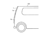
- FIG. 10 External view showing an example of the rear part of the vehicle 100 to which the drive device according to the embodiment of the present invention is applied.
- the figure for demonstrating the operation of the drive device 10. The figure for demonstrating the operation of the drive device 10.
- the figure for demonstrating the operation of the drive device 10. The figure for demonstrating the operation of the drive device 10.
- the figure for demonstrating the operation of the drive device 10. The figure for demonstrating the operation of the drive device 10.
- the figure for demonstrating the operation of the drive device 10. The figure for demonstrating the operation of the drive device 10.
- the figure for demonstrating the operation of the drive device 10. The figure for demonstrating the operation of the drive device 10.
- the figure for demonstrating the operation of the drive device 10. The figure for demonstrating the operation of the drive device 10.
- the figure for demonstrating the operation of the drive device 10. The figure for demonstrating the operation of the drive device 10.
- the figure for demonstrating the operation of the drive device 10. The figure for demonstrating the operation of the drive device 10.
- the figure for demonstrating the operation of the drive device 10. The figure for demonstrating the operation of the drive device 10.
- the figure for demonstrating the operation of the drive device 10. The figure for demonstrating the 1st modification of the drive device 10 which concerns on embodiment of this invention.
- the figure for demonstrating the 2nd modification of the drive device 10 which concerns on embodiment of this invention.
- FIG. 1 is an external view showing an example of the rear part of the vehicle 100 to which the drive device according to the embodiment of the present invention is applied.
- the vehicle 100 includes a door 1 that opens or closes the opening 100a formed at the rear of the vehicle 100.
- the open state is a state in which the opening 100a is open, and a state in which luggage and the like can be taken in and out of the vehicle 100 through the opening 100a.
- the closed state is a state in which the opening 100a is closed.
- the door 1 is a break-action tailgate including, for example, an upper door 1a and a lower door 1b.
- the door 1 is not limited to the tailgate of the vehicle 100, and may be, for example, a flip-up door for getting on and off.
- the upper door 1a is rotatably attached to the vehicle body via two hinges 2a 1 and 2a 2 .
- the lower door 1b is rotatably connected to the upper door 1a via two hinges 2b 1 and 2b 2 .
- the two hinges 2b 1 and 2b 2 are examples of connecting portions that connect the upper door 1a and the lower door 1b.
- hovere 2a when the two hinges 2a 1 and 2a 2 are not distinguished, they are simply referred to as "hinge 2a”.
- the two hinges 2b 1 and 2b 2 are not distinguished, they are simply referred to as "hinge 2b".
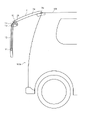
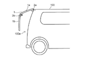
- FIGS. 2 and 3 are enlarged views showing an example of a door 1 provided with a drive device 10 according to an embodiment of the present invention.
- FIG. 2A shows a perspective view of the door 1
- FIG. 2B shows a side view of the door 1.
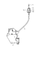
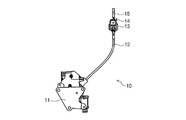
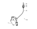
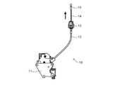
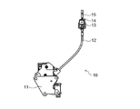
- FIG. 3 is a diagram showing a configuration example of the drive device 10 according to the embodiment of the present invention.
- the door 1 is provided with two types of hinges 2a and 2b and a drive device 10.
- the two types of hinges 2a and 2b are arranged apart from each other in the left-right direction of the door 1, that is, in the vehicle width direction.
- At least one of the drive unit 11 and the adjustment unit 60 is arranged between two hinges 2b provided apart in the vehicle width direction.
- the number of hinges 2a and 2b is not limited to two, and may be one or more for each.
- the hinges 2a and 2b are provided at the center of the door 1 in the vehicle width direction, and the drive device 10 is provided at the center of the door 1 in the vehicle width direction. It is provided near the left-right edge of the portion or the lower door 1b.
- the drive device 10 includes a drive unit 11, an outer casing 12, a guide unit 13, a cable 14, and a cable end 15.
- the drive unit 11 is a device that generates a driving force for driving the lower door 1b by winding and unwinding the cable 14.
- the upper door 1a is driven by a PLG (Power Lift Gate) unit.
- the drive unit 11 is provided at a position separated from the hinge 2b by a certain distance, near the lower end portion of the lower door 1b, and near the center portion in the left-right direction of the lower door 1b.
- the position where the drive unit 11 is provided is not limited to the vicinity of the central portion in the left-right direction of the lower door 1b, and may be near the edge portion in the left-right direction of the lower door 1b.
- the lower door 1b is a door having a recess formed from the inside of the vehicle toward the outside of the vehicle, it is preferable to provide the drive unit 11 in the space formed in the recess of the lower door 1b.
- the recess of the lower door 1b can be effectively used, so that it is possible to prevent the luggage compartment space from being narrowed by the drive unit 11.
- the drive unit 11 includes a motor and a power transmission unit such as a worm gear that transmits the rotation of the motor to the drum.
- the adjusting unit 60 changes the degree of bending of the lower door 1b with respect to the upper door 1a based on the driving force generated by the motor.
- the adjusting unit 60 includes the drum described above, the driving unit 11 described above, and the cable 14.
- the adjusting unit 60 generates a tensile force that pulls the cable 14 by winding the cable 14 due to the rotation of the drum.
- the cable 14 transmits a tensile force that attracts the upper door 1a and the lower door 1b based on the driving force generated by the driving unit 11.
- the cable 14 is, for example, a flexible cable obtained by twisting a metal wire, a resin fiber wire, or the like.
- One end of the cable 14 is connected to the drum provided in the drive unit 11.
- the other end of the cable 14 extends from the drive portion 11 to the guide portion 13 and from there to the cable end 15.
- the portion of the entire cable 14 from the drive portion 11 to the guide portion 13 is covered with an outer casing 12 for protecting the cable 14.
- the cable end 15 is a metal member for fixing the end of the cable 14 to the upper door 1a.
- the cable end 15 is fixed, for example, near the lower end of the upper door 1a.
- the guide portion 13 is a member that changes the guide direction while movably supporting the cable 14.
- the guide portion 13 includes, for example, a guide 13a for carrying the cable 14 shown in FIG. 2A, a bracket 13b for fixing the guide 13a to the door 1 shown in FIG. 2A, and a cable shown in FIG. 2A.
- the 14 is pulled out to the outside of the guide 13a, and is provided with a stopper 13c that hits the cable end 15 and stops the movement of the cable end 15 when the cable 14 is pulled toward the guide 13a.
- the degree of bending of the lower door 1b with respect to the upper door 1a can be reduced by winding the cable 14.
- the degree of bending of the lower door 1b with respect to the upper door 1a can be increased. Specific examples of the operation of the drive device 10 will be described later.
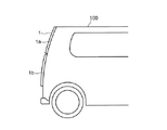
- FIGS. 4A to 11B are diagrams for explaining the operation of the drive device 10.
- FIG. 4A, 5A, 6A, 7A, 8A, 9A, 10A and 11A show the open / closed state of the door 1
- FIG. 4B, FIG. 5B, FIG. 6B, FIG. 7B, FIG. 8B, 9B, 10B and 11B show the operating state of the drive device 10.
- the cable 14 is unwound in conjunction with the opening operation of the upper door 1a, so that the degree of bending of the lower door 1b with respect to the upper door 1a increases.
- an obstacle such as a person or a wall is present in front of the door 1, it is possible to prevent the lower door 1b from coming into contact with the obstacle.
- the tensile force that attracts the upper door 1a and the lower door 1b is strengthened.
- the degree of bending of the lower door 1b with respect to the upper door 1a is reduced.
- the cable 14 is wound up in conjunction with the closing operation of the upper door 1a, so that the lower end portion of the lower door 1b can be prevented from coming into contact with the vehicle body.
- the drive unit 11 is provided at a position separated from the hinge 2b, which is a connecting portion, by a certain distance.
- a cable 14 is used in the adjusting unit 60 to change the degree of bending of the lower door 1b with respect to the upper door 1a by utilizing the driving force generated by the motor of the driving unit 11b.
- the drive unit 11 can be provided in the space formed in the recess of the lower door 1b. become.
- the concave portion of the lower door 1b can be effectively used, so that it is possible to prevent the luggage compartment space from being narrowed by the drive unit 11.
- a motor is combined with the hinge to drive the lower door of the break-action tailgate.
- the capacity of the motor is determined by the specifications such as the weight of the door, but the larger the capacity of the motor, the larger the size can be, which makes it difficult to arrange the motor in combination with the hinge. As a result, the degree of freedom in door design can be constrained.
- the degree of freedom in the design of the door 1 can be improved.
- FIG. 12 is a diagram for explaining a first modification of the drive device 10 according to the embodiment of the present invention.
- the drive device 10 according to the first modification is a device that drives the door 1 by converting the rotational motion of the motor into a linear motion.
- the drive device 10 according to the first modification has a drive unit 30 and a shaft unit 31 housed in the drive unit 30 and moving back and forth with respect to the drive unit 30.
- the drive device 10 according to the first modification generates a driving force for driving the upper door 1a or the lower door 1b by moving the shaft portion 31 forward and backward with respect to the drive portion 30.
- the lower end of the drive unit 30 is connected to the vicinity of the lower end of the lower door 1b by the first connection portion 30a.
- the first connection portion 30a is composed of a ball joint, a pin joint, a universal joint, and the like.
- the upper end portion of the shaft portion 31 is connected to the vicinity of the lower end portion of the upper door 1a by the second connecting portion 30b.
- the second connecting portion 30b is also composed of a ball joint, a pin joint, a universal joint and the like.
- the second connecting portion 30b is an example of a connecting portion that connects the upper door 1a and the shaft portion 31.
- the drive unit 30 is provided at a position separated from the second connection unit 30b by a certain distance.
- the drive unit 30 includes a motor and a power transmission unit such as a planetary gear and a screw nut that transmits the rotation of the motor to the shaft unit 31.
- the adjusting unit 60A shown in FIG. 12 increases the degree of bending of the lower door 1b with respect to the upper door 1a or the degree of bending of the lower door 1b with respect to the upper door 1a based on the driving force generated by the motor. Make it smaller.
- the adjusting unit 60A includes the above-mentioned power transmission unit and the shaft unit 31.
- the adjusting unit 60A expands and contracts the shaft unit 31 by converting the rotational motion of the motor into a linear motion by the power transmission unit.
- the rotational motion of the motor is converted into a linear motion by the power transmission unit and transmitted to the shaft unit 31.
- the shaft portion 31 moves forward.
- the forward movement is that the shaft portion 31 moves from the inside of the drive portion 30 toward the outside of the drive portion 30.
- the forward movement also means that the shaft portion 31 extends from the inside of the drive portion 30 toward the outside of the drive portion 30.
- the shaft unit 31 retracts.
- the retreat is that the shaft portion 31 moves from the outside of the drive portion 30 toward the inside of the drive portion 30.
- the retreat also means that the shaft portion 31 contracts from the outside of the drive portion 30 toward the inside of the drive portion 30.
- the drive unit 30 is provided at a position separated from the second connection unit 30b, which is a connection unit, by a certain distance.
- the adjusting unit 60A uses a shaft unit 31 that is connected to the upper door 1a and the lower door 1b and expands and contracts by utilizing the driving force generated by the motor of the driving unit 30.
- the drive unit 30 can be provided in the space formed in the recess of the lower door 1b.
- the concave portion of the lower door 1b can be effectively used, so that it is possible to prevent the luggage compartment space from being narrowed by the drive unit 30.
- the degree of freedom in designing the door 1 can be improved.
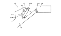
- FIG. 13 is a diagram for explaining a second modification of the drive device 10 according to the embodiment of the present invention.
- the drive device 10 according to the second modification is a device that drives the door 1 by using a link mechanism to which the rotational force of the motor is transmitted.
- the drive device 10 includes a drive unit 40, a first link 41 connected to the upper door 1a, and a second link 42 connected to the lower door 1b.
- the drive unit 40 is provided on the lower door 1b, and is a device that generates a driving force for driving the lower door 1b by rotating the second link 42.
- the drive unit 40 includes a motor and a rotation shaft connected to the second link 42.
- One end of the second link 42 is connected to the rotation shaft of the drive unit 40.
- One end of the first link 41 is rotatably connected to the other end of the second link 42.
- the other end of the first link 41 is rotatably connected to the upper door 1a.
- the lower door 1b is rotatably connected to the upper door 1a via a hinge 50.
- the drive unit 40 is provided at a position separated from the hinge 50 by a certain distance.
- the hinge 50 is composed of a ball joint, a pin joint, a universal joint, and the like.
- the adjusting unit 60B shown in FIG. 13 increases the degree of bending of the lower door 1b with respect to the upper door 1a based on the driving force generated by the motor, or the degree of bending of the lower door 1b with respect to the upper door 1a. To make it smaller.
- the adjusting unit 60B includes the rotation shaft of the driving unit 40 described above, the first link 41, and the second link 42.
- the adjusting unit 60B changes the degree of bending of the lower door 1b with respect to the upper door 1a by converting the rotational movement of the rotation axis of the driving unit 40 into a linear motion by the first link 41 and the second link 42. ..
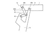
- 14 and 15 are diagrams for explaining the operation when the degree of bending of the lower door 1b with respect to the upper door 1a is increased.
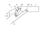
- 16 and 17 are diagrams for explaining the operation when the degree of bending of the lower door 1b with respect to the upper door 1a is reduced.
- the drive unit 40 is provided at a position separated from the hinges 50a and 50b by a certain distance.
- the adjusting unit 60B uses the driving force generated by the motor of the driving unit 40 to change the degree of bending of the lower door 1b with respect to the upper door 1a, so that the first link 41 and the second link 42 can be changed. Is used.
- the drive device 10 according to the second modification to the break-action door 1 the degree of freedom in designing the door 1 can be improved.
- the drive device is a drive device for driving a door including an upper door and a lower door rotatably connected to the upper door, and the upper door and the lower door can be rotated.
- a drive unit that is provided at a position separated from the connecting portion connected to the upper door and generates a driving force for driving the upper door or the lower door, and a bending of the lower door with respect to the upper door based on the driving force. It is provided with an adjustment unit that changes the degree.
- the adjusting unit includes a cable laid from the upper door to the lower door, and when increasing the degree of bending of the lower door with respect to the upper door, the cable is unwound and described. To reduce the degree of bending of the lower door with respect to the upper door, the cable is wound up.
- the adjusting portion includes a shaft portion that is connected to the upper door and the lower door and expands and contracts, and when the degree of bending of the lower door with respect to the upper door is increased, the shaft portion is extended. When reducing the degree of bending of the lower door with respect to the upper door, the shaft portion is shrunk.
- the adjusting unit includes a first link connected to the upper door and a second link connected to the lower door, and determines the degree of bending of the lower door with respect to the upper door.
- the connecting portion includes two connecting portions arranged apart from each other in the vehicle width direction, and at least one of the driving portion and the adjusting portion is arranged between the two connecting portions.
- the lower door is a door having a recess formed from the inside of the vehicle toward the outside of the vehicle, and at least one of the drive portion and the adjusting portion is provided in the space formed in the recess. Has been done.
- the drive device according to the present invention is useful as a device capable of improving the degree of freedom in door design.
Landscapes
- Engineering & Computer Science (AREA)
- Mechanical Engineering (AREA)
- Power-Operated Mechanisms For Wings (AREA)
Abstract
Description
駆動装置10は、駆動部11、アウターケーシング12、ガイド部13、ケーブル14、及びケーブルエンド15を備えている。
駆動部11は、ケーブル14の巻き取りと繰り出しを行うことによって、下側ドア1bを駆動する駆動力を発生する装置である。上側ドア1aは、PLG(Power Lift Gate)ユニットにより駆動される。
調整部60は、モータが発生する駆動力に基づいて、上側ドア1aに対する下側ドア1bの折れ曲がりの度合いを変化させる。具体的には、調整部60は、上述したドラムと、上述した駆動部11と、ケーブル14とを備えている。
ケーブル14は、駆動部11で発生した駆動力に基づいて、上側ドア1aと下側ドア1bとを引き合わせる引張力を伝達する。ケーブル14は、例えば、金属素線、樹脂繊維素線などを撚り合わせた可撓性を有するケーブルである。
ケーブルエンド15は、ケーブル14の端部を上側ドア1aに固定するための金属製の部材である。ケーブルエンド15は、例えば上側ドア1aの下端部付近に固定されている。
ガイド部13は、ケーブル14を移動可能に支持しながらその案内方向を転換する部材である。
、ケーブル14が繰り出される。これにより、上側ドア1aと下側ドア1bとを引き合わせる引張力が弱められる。従って、図5Aに示すように、下側ドア1bが重力によって垂れ下がり、上側ドア1aに対する下側ドア1bの折れ曲がりの度合いが大きくなる。
図12に示される調整部60Aは、モータが発生する駆動力に基づいて、上側ドア1aに対する下側ドア1bの折れ曲がりの度合いを大きくし、又は上側ドア1aに対する下側ドア1bの折れ曲がりの度合いを小さくする。具体的には、調整部60Aは、上述した動力伝達部と、軸部31とを備えている。
直線運動に変換されて、軸部31に伝達される。これにより、軸部31が前進する。前進は、軸部31が駆動部30の内部から駆動部30の外部に向かって移動することである。前進は、軸部31が、駆動部30の内部から駆動部30の外部に向かって伸びることでもある。
駆動部40は、下側ドア1bに設けられており、第2リンク42を回転させることにより、下側ドア1bを駆動する駆動力を発生する装置である。駆動部40は、モータと、第2リンク42に接続される回転軸とを備えている。
図13に示される調整部60Bは、モータが発生する駆動力に基づいて、上側ドア1aに対する下側ドア1bの折れ曲がりの度合いを大きくし、又は、上側ドア1aに対する下側ドア1bの折れ曲がりの度合いを小さくする。具体的には、調整部60Bは、上述した駆動部40の回転軸と、第1リンク41と、第2リンク42とを備えている。
1a 上側ドア
1b 下側ドア
2a ヒンジ
2a1 ヒンジ
2a2 ヒンジ
2b ヒンジ
2b1 ヒンジ
2b2 ヒンジ
10 駆動装置
11 駆動部
12 アウターケーシング
13 ガイド部
13a ガイド
13b ブラケット
13c ストッパー
14 ケーブル
15 ケーブルエンド
30 駆動部
30a 第1接続部
30b 第2接続部
31 軸部
40 駆動部
41 第1リンク
42 第2リンク
42a 第1回転方向
42b 第2回転方向
50a ヒンジ
50b ヒンジ
60 調整部
60A 調整部
60B 調整部
100 車両
100a 開口部
Claims (6)
- 上側ドアと前記上側ドアに回転可能に連結されている下側ドアとを備えたドアを駆動する駆動装置であって、
前記上側ドアと前記下側ドアとを回転可能に連結する連結部から隔てた位置に設けられ、前記上側ドア又は前記下側ドアを駆動する駆動力を発生する駆動部と、
前記駆動力に基づいて前記上側ドアに対する前記下側ドアの折れ曲がりの度合いを変化させる調整部と、
を備える駆動装置。 - 前記調整部は、前記上側ドアから前記下側ドアに渡って敷設されているケーブルを備え、
前記上側ドアに対する前記下側ドアの折れ曲がりの度合いを大きくする場合、前記ケーブルを繰り出し、
前記上側ドアに対する前記下側ドアの折れ曲がりの度合いを小さくする場合、前記ケーブルを巻き取る請求項1に記載の駆動装置。 - 前記調整部は、前記上側ドアと前記下側ドアとに接続されて伸縮する軸部を備え、
前記上側ドアに対する前記下側ドアの折れ曲がりの度合いを大きくする場合、前記軸部を伸ばし、
前記上側ドアに対する前記下側ドアの折れ曲がりの度合いを小さくする場合、前記軸部を縮める請求項1に記載の駆動装置。 - 前記調整部は、前記上側ドアに接続されている第1リンクと、前記下側ドアに接続されている第2リンクとを備え、
前記上側ドアに対する前記下側ドアの折れ曲がりの度合いを大きくする場合、前記第1リンクと前記第2リンクの成す角度を大きくし、
前記上側ドアに対する前記下側ドアの折れ曲がりの度合いを小さくする場合、前記角度を小さくする請求項1に記載の駆動装置。 - 前記連結部は、車幅方向において離れて配置される2つの連結部を含み、
前記駆動部及び前記調整部の少なくとも一方は、前記2つの連結部の間に配置されている請求項1から4の何れか一項に記載の駆動装置。 - 前記下側ドアは、車両内側から車両外側に向かって凹む凹部が形成されているドアであり、
前記駆動部及び前記調整部の少なくとも一方は、前記凹部に形成されている空間に設けられている請求項1から5の何れか一項に記載の駆動装置。
Priority Applications (2)
| Application Number | Priority Date | Filing Date | Title |
|---|---|---|---|
| CN202180077591.0A CN116783362A (zh) | 2020-12-02 | 2021-12-02 | 驱动装置 |
| US18/039,499 US12203311B2 (en) | 2020-12-02 | 2021-12-02 | Driving device |
Applications Claiming Priority (2)
| Application Number | Priority Date | Filing Date | Title |
|---|---|---|---|
| JP2020-200332 | 2020-12-02 | ||
| JP2020200332A JP7510861B2 (ja) | 2020-12-02 | 2020-12-02 | 駆動装置 |
Publications (1)
| Publication Number | Publication Date |
|---|---|
| WO2022118908A1 true WO2022118908A1 (ja) | 2022-06-09 |
Family
ID=81853953
Family Applications (1)
| Application Number | Title | Priority Date | Filing Date |
|---|---|---|---|
| PCT/JP2021/044191 Ceased WO2022118908A1 (ja) | 2020-12-02 | 2021-12-02 | 駆動装置 |
Country Status (4)
| Country | Link |
|---|---|
| US (1) | US12203311B2 (ja) |
| JP (1) | JP7510861B2 (ja) |
| CN (1) | CN116783362A (ja) |
| WO (1) | WO2022118908A1 (ja) |
Cited By (1)
| Publication number | Priority date | Publication date | Assignee | Title |
|---|---|---|---|---|
| US20240026722A1 (en) * | 2020-12-02 | 2024-01-25 | Hi-Lex Corporation | Driving device |
Families Citing this family (3)
| Publication number | Priority date | Publication date | Assignee | Title |
|---|---|---|---|---|
| CN116252597A (zh) * | 2023-02-27 | 2023-06-13 | 重庆长安汽车股份有限公司 | 一种背门结构总成及车辆 |
| JP2024172205A (ja) * | 2023-05-31 | 2024-12-12 | 株式会社ハイレックスコーポレーション | 駆動装置 |
| US12305440B1 (en) * | 2024-08-19 | 2025-05-20 | Ningbo Powernice Intelligent Technology Co., Ltd. | Single motor-driven double push rod electric vehicle tailgate system |
Citations (5)
| Publication number | Priority date | Publication date | Assignee | Title |
|---|---|---|---|---|
| JPS61101088U (ja) * | 1984-12-11 | 1986-06-27 | ||
| JP2005299232A (ja) * | 2004-04-12 | 2005-10-27 | Mitsubishi Motors Corp | 車両のテールゲート装置及びテールゲート開閉方法 |
| JP2009173254A (ja) * | 2007-12-25 | 2009-08-06 | Aisin Seiki Co Ltd | 車両用中折れ式ドアの支持装置 |
| US20180037096A1 (en) * | 2015-04-24 | 2018-02-08 | Bayerische Motoren Werke Aktiengesellschaft | Pivotable Motor Vehicle Tailgate |
| JP2020029252A (ja) * | 2018-08-20 | 2020-02-27 | コンチネンタル オートモーティヴ ゲゼルシャフト ミット ベシュレンクテル ハフツングContinental Automotive GmbH | 車両用トランクカバー及びその開放方法 |
Family Cites Families (11)
| Publication number | Priority date | Publication date | Assignee | Title |
|---|---|---|---|---|
| JPS61101088A (ja) | 1984-10-24 | 1986-05-19 | Hitachi Ltd | 半導体レ−ザの製造方法 |
| US5992918A (en) * | 1998-05-07 | 1999-11-30 | General Motors Corporation | Bi-fold gull wing vehicle door |
| US6454341B2 (en) * | 2000-06-20 | 2002-09-24 | Meritor Light Vehicle Systems, Inc. | Lift gate for a motor vehicle |
| US6471284B2 (en) * | 2001-03-05 | 2002-10-29 | General Motors Corporation | Rear end closure assembly for an automotive vehicle |
| DE20317018U1 (de) * | 2003-11-05 | 2004-02-26 | Land, Bernd | Waagrecht geteilte, klappbare Heckklappe für alle Fahrzeuge |
| EP1840310B1 (en) * | 2006-03-31 | 2010-12-15 | Valeo Sicherheitssysteme GmbH | Adjusting device having a spindle drive |
| JP2009101872A (ja) * | 2007-10-23 | 2009-05-14 | Kanto Auto Works Ltd | 車輌の扉開閉機構 |
| CN206299269U (zh) * | 2015-09-30 | 2017-07-04 | 爱信精机株式会社 | 车门开/关设备 |
| DE102016003155B4 (de) * | 2016-03-15 | 2020-07-09 | Audi Ag | Kraftfahrzeug mit automatischem Karosserieklappenantrieb |
| CN111075302A (zh) * | 2018-10-22 | 2020-04-28 | 麦格纳覆盖件有限公司 | 带摩擦的自调节式平衡机构 |
| JP2022088083A (ja) * | 2020-12-02 | 2022-06-14 | 株式会社ハイレックスコーポレーション | 駆動装置 |
-
2020
- 2020-12-02 JP JP2020200332A patent/JP7510861B2/ja active Active
-
2021
- 2021-12-02 WO PCT/JP2021/044191 patent/WO2022118908A1/ja not_active Ceased
- 2021-12-02 CN CN202180077591.0A patent/CN116783362A/zh active Pending
- 2021-12-02 US US18/039,499 patent/US12203311B2/en active Active
Patent Citations (5)
| Publication number | Priority date | Publication date | Assignee | Title |
|---|---|---|---|---|
| JPS61101088U (ja) * | 1984-12-11 | 1986-06-27 | ||
| JP2005299232A (ja) * | 2004-04-12 | 2005-10-27 | Mitsubishi Motors Corp | 車両のテールゲート装置及びテールゲート開閉方法 |
| JP2009173254A (ja) * | 2007-12-25 | 2009-08-06 | Aisin Seiki Co Ltd | 車両用中折れ式ドアの支持装置 |
| US20180037096A1 (en) * | 2015-04-24 | 2018-02-08 | Bayerische Motoren Werke Aktiengesellschaft | Pivotable Motor Vehicle Tailgate |
| JP2020029252A (ja) * | 2018-08-20 | 2020-02-27 | コンチネンタル オートモーティヴ ゲゼルシャフト ミット ベシュレンクテル ハフツングContinental Automotive GmbH | 車両用トランクカバー及びその開放方法 |
Cited By (1)
| Publication number | Priority date | Publication date | Assignee | Title |
|---|---|---|---|---|
| US20240026722A1 (en) * | 2020-12-02 | 2024-01-25 | Hi-Lex Corporation | Driving device |
Also Published As
| Publication number | Publication date |
|---|---|
| US12203311B2 (en) | 2025-01-21 |
| JP7510861B2 (ja) | 2024-07-04 |
| US20240003178A1 (en) | 2024-01-04 |
| JP2022088081A (ja) | 2022-06-14 |
| CN116783362A (zh) | 2023-09-19 |
Similar Documents
| Publication | Publication Date | Title |
|---|---|---|
| WO2022118908A1 (ja) | 駆動装置 | |
| CN101445082A (zh) | 门边缘保护装置 | |
| US8607656B2 (en) | Drive device for a tilt element of a motor vehicle | |
| JP2011094423A (ja) | パワーリフトゲート | |
| CN1791729A (zh) | 铰链装置 | |
| EP4174269B1 (en) | Door opening and closing device | |
| JP4216787B2 (ja) | 往復動用駆動装置 | |
| EP2546447B1 (en) | A motor vehicle with a sliding door and an actuation mechanism for the sliding door | |
| JP2001280000A (ja) | 車両用開閉体の開閉装置 | |
| WO2022118909A1 (ja) | 駆動装置 | |
| JP2007196925A (ja) | スイングスライドドアの配索構造 | |
| JP6164654B2 (ja) | スライド構造体用の給電構造 | |
| US20230304350A1 (en) | Power side door actuator having rack and pinion drive | |
| CN216921797U (zh) | 一种车门开启结构及车辆 | |
| JP2023086334A (ja) | ケーブル案内構造及び駆動装置 | |
| US7290823B2 (en) | Closing unit | |
| JP2682832B2 (ja) | ウインドオープナ | |
| JP2003336441A (ja) | 車両用自動開閉装置 | |
| CN223880963U (zh) | 用于车辆的后备箱盖的铰链结构 | |
| JP5075604B2 (ja) | 車両用ドア開閉装置 | |
| JP2024172205A (ja) | 駆動装置 | |
| WO2026070905A1 (ja) | 車両ドア開閉装置 | |
| CN221942229U (zh) | 电动后备箱盖的驱动装置和包括该驱动装置的车辆 | |
| JP4781124B2 (ja) | 開閉体のパワー開閉装置 | |
| JP2005271615A (ja) | 車両用自動開閉装置 |
Legal Events
| Date | Code | Title | Description |
|---|---|---|---|
| 121 | Ep: the epo has been informed by wipo that ep was designated in this application |
Ref document number: 21900659 Country of ref document: EP Kind code of ref document: A1 |
|
| WWE | Wipo information: entry into national phase |
Ref document number: 202180077591.0 Country of ref document: CN |
|
| WWE | Wipo information: entry into national phase |
Ref document number: 18039499 Country of ref document: US |
|
| NENP | Non-entry into the national phase |
Ref country code: DE |
|
| 122 | Ep: pct application non-entry in european phase |
Ref document number: 21900659 Country of ref document: EP Kind code of ref document: A1 |