WO2022118857A1 - 植毛装置、及び、植毛装置を用いたかつらの製造方法 - Google Patents
植毛装置、及び、植毛装置を用いたかつらの製造方法 Download PDFInfo
- Publication number
- WO2022118857A1 WO2022118857A1 PCT/JP2021/043944 JP2021043944W WO2022118857A1 WO 2022118857 A1 WO2022118857 A1 WO 2022118857A1 JP 2021043944 W JP2021043944 W JP 2021043944W WO 2022118857 A1 WO2022118857 A1 WO 2022118857A1
- Authority
- WO
- WIPO (PCT)
- Prior art keywords
- hair
- base
- piece
- movable piece
- loop
- Prior art date
- Legal status (The legal status is an assumption and is not a legal conclusion. Google has not performed a legal analysis and makes no representation as to the accuracy of the status listed.)
- Ceased
Links
Images





Classifications
-
- A—HUMAN NECESSITIES
- A41—WEARING APPAREL
- A41G—ARTIFICIAL FLOWERS; WIGS; MASKS; FEATHERS
- A41G3/00—Wigs
Definitions
- the present invention relates to a hair transplanting device for planting hair on a wig base and a method for manufacturing a wig using the hair transplanting device.
- the wig is made by planting hair such as natural hair or artificial hair on a wig base formed according to the shape of the head and the area covering the head.
- the wig base is formed in a mesh shape by a linear portion made of a fiber member.
- a forceps provided with one hook needle may be used to form a loop in the hair.
- the hair is pulled out from the loop to form a knot on the hair.
- Patent Document 1 it is a burden on the operator to manually transplant hairs one by one on the wig base using only one hook needle at the tip of the forceps. There was a problem that it was big.
- an object of the present invention is to provide a hair transplanting device that can reduce the burden on the operator when transplanting hair to a wig base, and a method for manufacturing a wig using the hair transplanting device.
- the hair-implanting device of the present invention is a hair-implanting device that implants hair on a wig base, and has a base holding mechanism that holds the wig base and a first end portion that grips one piece of the hair that is implanted on the wig base.
- a chuck mechanism having a grip portion and a second end grip portion that grips the other hair piece of the hair, and a U-shaped hair held by the first end grip portion and the second end grip portion. Folded in half, guided from one side of the wig base held by the base holding mechanism to the other side, folded back at the linear portion of the wig base, and from the other side of the wig base.
- the hook needle mechanism that pulls out the hair folded in half in a U shape and the U-shaped first loop of the hair that is pulled out to one side side of the wig base by the hook needle mechanism are expanded.
- the hair has a loop holding mechanism for holding the first loop, and a forceps mechanism for forming a knot on the hair having the first loop and implanting the hair on the wig base by using a forceps.
- the forceps provided in the forceps mechanism are interposed between a rod-shaped base, a first movable piece that is openly and closably provided with respect to the base and can hold the hair with the hair sandwiched between the bases, and the base.
- the second movable piece is provided at a position facing the first movable piece so as to be openable and closable with respect to the base independently of the first movable piece, and the hair can be sandwiched and held between the first movable piece and the base. With a piece.
- the forceps mechanism moves the forceps to a predetermined position while holding the hair piece at the base and the first movable piece, while holding the hair piece at the base and the second movable piece, and the base and the second movable piece.
- the hair can be automatically transplanted to the wig base. Therefore, unlike the conventional method, it is not necessary for the operator to hold the forceps and transplant the hair one by one to the wig base with the forceps, and the hair is transplanted to the wig base by that amount. The burden on the worker can be reduced.
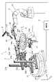
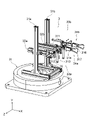
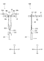
- FIGS. 1 and 2 are schematic views showing the overall configuration of the flocking device 1 according to the present embodiment.
- two directions orthogonal to each other in the horizontal plane are the X-axis direction and the Z-axis direction
- the X-axis direction is the front-back direction
- the Z-axis direction is the width direction.
- the vertical direction orthogonal to the X-axis direction and the Z-axis direction is defined as the Y-axis direction.
- the flocking device 1 has a base holding mechanism 2, a chuck mechanism 3, a loop holding mechanism 4, a forceps mechanism 5, and a hooking mechanism for a control unit 6 having a CPU (Central Processing Unit) configuration that collectively controls the flocking device 1. It has a configuration in which 7 is connected.
- the control unit 6 has various programs such as a hair-planting operation program stored in advance in a ROM (Read Only Memory) (not shown) in the control unit 6 in response to various commands input via an operation unit (not shown). Is read out and expanded on a RAM (Random Access Memory) (not shown) in the control unit 6 to control the entire hair planting device 1 according to these various programs and realize various functions.
- ROM Read Only Memory
- RAM Random Access Memory
- the hook needle mechanism 7 is arranged at the center of the base holding mechanism 2, and the chuck mechanism 3 and the loop holding mechanism are arranged around the base holding mechanism 2 around the base holding mechanism 2. 4 and the forceps mechanism 5 are arranged.
- the forceps mechanism 5 is arranged to face the chuck mechanism 3 with the base holding mechanism 2 interposed therebetween.
- the loop holding mechanism 4 is arranged above the forceps mechanism 5, and the loop holding mechanism 4 is arranged facing the chuck mechanism 3 with the base holding mechanism 2 interposed therebetween.
- a wig base B for transplanting hair (not shown) such as natural hair or artificial hair is placed on the base holding mechanism 2, and the base holding mechanism 2 and a chuck are controlled by the control unit 6.
- the control unit 6 By operating the mechanism 3, the loop holding mechanism 4, the forceps mechanism 5, and the hook needle mechanism 7 in a predetermined trajectory set in advance, the hairs are tied to the linear portion of the wig base B one by one. Multiple hairs are sequentially transplanted to the wig base B.
- the base holding mechanism 2 has an annular pedestal 22a, 22b on which the wig base B is placed, and the pedestal 22b is placed above the pedestal 22a so that the center of the pedestal 22a, 22b is coaxially located. Have been placed.
- the lower pedestal 22a has a larger outer diameter than the upper pedestal 22b, and the spherical crown-shaped or hemispherical wig base B formed according to the shape of the wig user's head forms the pedestals 22a and 22b. It is placed so as to cover it.
- the pedestal 22a located below has a larger outer diameter than the pedestal 22b above, the open end of the wig base B can be widened and held in a spherical crown shape or a hemispherical shape.
- the base holding mechanism 2 has a pedestal drive unit 21 connected to the control unit 6, and the pedestal drive unit 21 moves the pedestal 22a in the horizontal plane in the X-axis direction in response to an operation command from the control unit 6. And move in the Z-axis direction.
- the pedestal drive unit 21 can move the wig base B spread on the upper pedestal 22b in the X-axis direction and the Z-axis direction, and can adjust the insertion position where the hook needle 23, which will be described later, inserts into the wig base B.
- the crochet mechanism 7 includes a crochet hook 23 extending along the Y-axis direction arranged in the hollow space of the pedestals 22a and 22b of the base holding mechanism 2, and a crochet hook driving unit 24 for moving the crochet hook 23 in the Y-axis direction.
- the hook needle drive unit 24 is connected to the control unit 6, and raises or lowers the hook needle 23 along the Y-axis direction in response to an operation command from the control unit 6.
- the configuration such as the shape of the hook needle 23 will be described later.
- the hook needle 23 is lowered along the Y-axis direction by the hook needle drive unit 24, so that the tip of the hook needle moves below the pedestal 22b on the upper side and is inserted into the wig base B mounted on the pedestal 22b.
- the tip of the hook is located below the wig base B.
- the hook needle 23 can be inserted into the wig base B by ascending along the Y-axis direction by the hook needle drive unit 24 from the state where the tip of the hook needle is located below the wig base B.
- the hook needle mechanism 7 executes the insertion of the hook needle 23 into the wig base B and the pulling out of the inserted hook needle 23 from the wig base B, and the base holding mechanism 2 moves the wig base B. , The insertion position of the hook needle 23 with respect to the wig base B is determined.
- the positions of the hook 23 in the X-axis direction and the Z-axis direction are fixed, and the crochet base B is moved in the X-axis direction and the Z-axis direction by the base holding mechanism 2, so that the crochet base B is provided with respect to the crochet base B.
- the insertion position of the hook needle 23 is adjusted has been described, the present invention is not limited to this. For example, even if the wig base B is fixed to the base holding mechanism 2 and the hook needle 23 is moved in the X-axis direction and the Z-axis direction by the hook needle mechanism 7, the insertion position of the hook needle 23 with respect to the wig base B is adjusted. good.
- One holding mechanism 33a is provided with a first end gripping portion 34a capable of picking and holding one end of the hair (also referred to as a hair piece), and the other holding mechanism 33b is provided with the other holding mechanism 33b of the hair.
- a second end grip portion 34b is provided that can pinch and hold the end (also referred to as a hair piece). Since the holding mechanisms 33a and 33b according to the present embodiment also have the same configuration, the following description will be given mainly focusing on the holding mechanism 33a. Further, since the first end grip portion 34a and the second end grip portion 34b according to the present embodiment have the same configuration, the following description mainly focuses on the first end grip portion 34a.
- the holding mechanism 33a includes a front-rear cylinder 311 for moving the first end grip portion 34a in the X-axis direction, and a first end grip portion 34a along the Z-axis direction orthogonal to the X-axis direction in the horizontal plane.
- the installation portion 35 is provided with left and right cylinders 312 for moving and upper and lower cylinders 313 for moving the first end grip portion 34a in the Y-axis direction.
- these front and rear cylinders 311 and left and right cylinders 312 and upper and lower cylinders 313 are connected to the control unit 6, and the front and rear cylinders 311 use the front and rear cylinders 311 to move the first end grip portion 34a back and forth in response to an operation command from the control unit 6. It is moved along the X-axis direction, which is the direction, the first end grip portion 34a is moved along the Z-axis direction, which is the left-right direction, by the left and right cylinders 312, and the first end grip portion 34a is moved up and down by the upper and lower cylinders 313. It is moved along the Y-axis direction, which is the direction.
- the first end grip portion 34a has a first grip piece 316 and a second grip piece 317, and the first grip piece 316 and the second grip piece 316 are provided by the opening / closing cylinder 314 in response to an operation command from the control unit 6.
- 317 opens and closes.
- the first gripping piece 316 and the second gripping piece 317 are formed in a rod shape, and when in the closed state, the tips thereof are in close contact with each other and can grip one hair. Further, when the first gripping piece 316 and the second gripping piece 317 are opened, the hair gripped at the tip portion can be separated.
- the chuck mechanism 3 individually adjusts the positions of the first end grip portion 34a and the second end grip portion 34b by the front / rear cylinder 311, the left / right cylinder 312, and the upper / lower cylinder 313, respectively, and determines the positions.
- the first end grip portion 34a and the second end grip portion 34b can be moved to a position where the hair at the position can be gripped.
- the chuck mechanism 3 can grip the hair by opening and closing the first grip piece 316 and the second grip piece 317 of the first end grip portion 34a and the second end grip portion 34b, and grip the first end portion.
- the hair By adjusting the positions of the portion 34a and the second end grip portion 34b, the hair can be held in a straight line, one hair piece and the other hair piece can be separated and arranged, or one hair piece can be arranged. And the other piece of hair can be placed in close proximity.
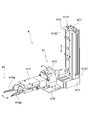
- the loop holding mechanism 4 includes an opening / closing locking portion 42 for expanding the first loop (described later) formed on the hair and holding the hollow loop inner region of the first loop, and the hair. It has a movable portion 41 for adjusting the position of the open / close locking portion 42.
- the movable portion 41 includes a vertically movable portion 412 provided in the support portion 411, a front-rear movable portion 413 provided in the lower end portion 4121 of the vertically movable portion 412, and a fixed portion 415 to the front-rear movable portion 413.
- a rotating portion 416 provided is provided.
- the support portion 411 is formed in a strut shape, and the concave second guide portion 4122 of the vertically movable portion 412 is fitted into the convex first guide portion 4111 formed along the longitudinal direction, and the first guide portion is formed.
- a vertically movable portion 412 is slidably provided along the 4111 in the longitudinal direction of the support portion 411.
- the vertically movable portion 412 has a configuration connected to the control unit 6, slides in the vertical direction in response to an operation command from the control unit 6, and determines the height position of the hair locked to the hook needle 23.
- the open / close locking portion 42 which will be described later, can be positioned at the position.
- the front-back movable portion 413 is provided on the lower end portion 4121 of the vertically movable portion 412 so as to be slidable along a direction orthogonal to the sliding direction of the vertically movable portion 412.
- the front-rear movable portion 413 has a configuration connected to the control unit 6, slides in the front-rear direction in response to an operation command from the control unit 6, and moves to a predetermined position such as the position of the hair locked to the hook needle 23.
- the open / close locking portion 42 can be positioned.
- a fixed portion 415 to which the rotating portion 416 is fixed is provided at the tip of the front-rear movable portion 413.
- the rotating portion 416 is provided on the fixed portion 415 so as to be rotatable 360 degrees around the axial direction with the sliding direction of the front-rear movable portion 413 as the axial direction.
- the rotating unit 416 has a configuration connected to the control unit 6, rotates by a predetermined angle in a predetermined direction in response to an operation command from the control unit 6, and becomes a state of hair locked to the hook needle 23. At the same time, the open / close locking portion 42 can be rotated.
- the opening / closing locking portion 42 is fixed to the rotating portion 416 at the other end facing the one end rotatably provided in the fixing portion 415.
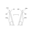
- the opening / closing locking portion 42 has a first locking piece 418a, a second locking piece 418b, and an opening / closing movable portion 417 that allows the first locking piece 418a and the second locking piece 418b to be opened and closed freely. ..
- the open / close movable portion 417 is provided with the roots of the first locking piece 418a and the second locking piece 418b rotatably, and the tips of the first locking piece 418a and the second locking piece 418b. Move the portion closer to the portion and move the tip portion away from the portion.
- the open / close movable portion 417 has a configuration connected to the control unit 6, and rotates the root portions of the first locking piece 418a and the second locking piece 418b in response to an operation command from the control unit 6.
- the tips of the first locking piece 418a and the second locking piece 418b are brought into close contact with each other, or the tips are separated from each other in an open state.
- the first locking piece 418a and the second locking piece 418b have tip portions 419a and 419b that are symmetrical and have a flat sharp end portion.
- the tip portions 419a and 419b are formed on the inner surface with a contact surface 421 that comes into contact with the tip portions 419a and 419b in the closed state. Further, the tip portions 419a and 419b are formed with a barbed-shaped locking portion 420 having a mountain portion facing outward from the root on the outer surface near the sharp end portion.
- the first locking piece 418a and the second locking piece 418b lock the locking portions 420 of the tip portions 419a and 419b to the first loop of the hair in the closed state, and are in the open state in this state. , The area in the loop of the first loop can be expanded.
- the forceps mechanism 5 has a forceps 52 and a forceps movable portion 51 that moves the forceps 52 to a predetermined position.
- the forceps movable portion 51 has a base 511, a first arm portion 512 having one end rotatably provided on a horizontal plane at the upper end of the base 511, and one end at the other end of the first arm portion 512.
- a second arm portion 513 rotatably provided in a vertical plane, a third arm portion 514 having one end rotatably provided in a vertical plane at the other end of the second arm portion 513, and a third arm.
- the other end of the portion 514 has a fourth arm portion 515 whose one end is rotatably provided in a vertical plane.
- the fourth arm portion 515 has a rotation surface of the other end portion located at a right angle to the rotation surface of the one end portion connected to the third arm portion 514, and the rotation surface of the other end portion.
- a forceps 52 is rotatably provided on the surface.
- the fourth arm portion 515 changes the direction of the forceps 52 provided at the other end portion from the upper side to the lower side or from the lower side to the upper side by rotating one end portion with respect to the third arm portion 514.
- the forceps mechanism 5 moves the first arm portion 512, the second arm portion 513, the third arm portion 514, and the fourth arm portion 515 in a predetermined locus in response to an operation command from the control unit 6. Then, move the forceps to the predetermined position with respect to the hair.
- 7A of FIG. 7 is a perspective view showing a configuration when the forceps 52 is viewed from a predetermined one-way side
- 7B of FIG. 7 is a perspective view showing a configuration when the forceps 52 is viewed from the other direction side. be.
- the forceps 52 are provided with fixing plates 5211 on both side surfaces of the support substrate 520, respectively, one fixing plate 5211 is provided with a first rotating cylinder 521a, and the other.
- a second rotating cylinder 521b is provided on the fixed plate 5211.
- the first rotation cylinder 521a rotates the first rotation support portion 5123a via the connecting portion 5125 and the second rod 5122 provided at the tip of the first rod 5212 by advancing and retreating the first rod 5212. .
- the first rotation support portion 5123a is made of an L-shaped plate material, and is rotatably provided on the support substrate 520 with the center of the corner portion as a fulcrum 5124.
- a second rod 5122 is rotatably provided at one end, a first movable piece 54 is fixed to the other end, and a second rod 5122 is fixed by a first rotation cylinder 521a. As the rod moves forward and backward, it rotates around the fulcrum 5124, and the first movable piece 54 at the other end is opened and closed with respect to the base 53.
- the second rotating cylinder 521b By advancing and retreating the first rod 5212, the second rotating cylinder 521b passes through the connecting portion 5125 and the second rod 5122 provided at the tip of the first rod 5212, and the second rotation is performed with the fulcrum 5124 as the rotating shaft. Rotate the dynamic support 5123b. Since the second rotation support portion 5123b has the same configuration as the first rotation support portion 5123a, the description thereof is omitted here. In the second rotation support portion 5123b, the second rod 5122 advances and retreats by the second rotation cylinder 521b and rotates around the fulcrum 5124, so that the second movable piece 55 at the other end is directed with respect to the base 53. Open and close.
- the support substrate 520, the fixing plate 5211, the connecting portion 5125, the first rod 5212, the second rod 5122, the first rotating support portion 5123a, and the second rotating cylinder 521b are made of, for example, aluminum, stainless steel, titanium, iron, or the like. It is made of metal material.
- the forceps 52 is provided with a base 53, a first movable piece 54 provided along the base 53, and a second movable piece 55 also provided along the base 53 at the tip of the support substrate 520. ..
- the base 53, the first movable piece 54, and the second movable piece 55 are formed in a rod shape by, for example, a metal material such as aluminum, stainless steel, titanium, or iron.
- the base portion 53 is formed, for example, into a linearly extending square strut shape, and is fixed to the support substrate 520 via the fixing portion 530. Further, when the first movable piece 54 described later is in the closed state, the base 53 is in contact with the first side surface 531 when the first movable piece 54 is in contact with the first side surface 531 and the second movable piece 55 described later is in the closed state. The second movable piece 55 abuts on the other second side surface 532 facing the first side surface 531.
- the first movable piece 54 is formed in the shape of a square strut extending linearly, and a recess 541 is formed in the vicinity of the tip portion of the inner surface that abuts on the first side surface 531 of the base portion 53.
- the first rotation support portion 5123a is rotated by the advance / retreat of the second rod 5122 by the first rotation cylinder 521a, and the tip thereof is It has a structure that can be opened and closed.
- the first movable piece 54 makes a first rotation when the first rod 5212 advances toward the tip end side of the forceps 52 in the direction CL by the first rotation cylinder 521a.
- the support portion 5123a rotates, and the tip portion rotates in a direction approaching the base portion 53.
- the first movable piece 54 is in contact with the inner surface facing the base 53 and the first side surface 531 of the base 53, and the recess 541 forms a holding region ER1 which is a hollow region between the first movable piece 54 and the base 53. It will be closed.
- the inner surface of the tip portion is formed flat according to the shape of the first side surface 531 of the base portion 53, and when the first movable piece 54 is closed, the inner surface of the tip portion is formed on the base portion 53.
- the holding region ER1 formed between the recess 541 and the base 53 is in close contact with the first side surface 531 without a gap, and is in a non-communication state with the outer space.
- the first movable piece 54 is supported by the first rotation when the first rod 5212 is retracted toward the root side of the forceps 52 by the first rotation cylinder 521a.
- the portion 5123a rotates, and the tip portion rotates in a direction away from the base portion 53.
- the holding region ER1 which is a hollow region in which the inner surface facing the base 53 is separated from the first side surface 531 of the base 53 and is formed between the first movable piece 54 and the base 53 by the recess 541 is the outer space. It becomes an open state that communicates with.
- the second movable piece 55 is formed of a square strut extending linearly, and the inner surface abutting on the second side surface 532 of the base 53 is formed flat to match the shape of the second side surface 532 of the base 53. .. As shown in 8A and 8B of FIG. 8, in the second movable piece 55, the second rotation support portion 5123b rotates as the second rod 5122 (FIG. 7) moves forward and backward by the second rotation cylinder 521b. The tip can be opened and closed.
- the second movable piece 55 rotates second when the second rod 5122 advances toward the tip end side of the forceps 52 in the direction CL by the second rotation cylinder 521b.
- the support portion 5123b rotates, and the tip portion rotates in a direction approaching the base portion 53.
- the second movable piece 55 is in a closed state in which the inner surface facing the base 53 and the second side surface 532 of the base 53 are in close contact with each other without a gap.
- the second movable piece 55 supports the second rotation when the first rod 5212 retracts in the direction OP toward the root side of the forceps 52 by the second rotation cylinder 521b.
- the portion 5123b rotates and the tip portion rotates in a direction away from the base portion 53.
- the second movable piece 55 is in an open state in which the inner surface facing the base 53 is separated from the second side surface 532 of the base 53.
- the forceps 52 operate the first rotating cylinder 521a and the second rotating cylinder 521b in response to an operation command from the control unit 6, and during the flocking operation, the first movable piece 54 and the second movable piece 54 at predetermined timings. Open and close 55.
- Example of hair transplanting operation by a hair transplanting device (7-1) Loop forming operation
- the base holding mechanism 2, the chuck mechanism 3, the loop holding mechanism 4 and the hook needle mechanism 7 are controlled by an operation command from the control unit 6.
- the loop forming operation for forming the first loop on the hair will be described below with reference to FIGS. 9 to 14.
- Y1 indicates an upward direction in the Y-axis direction
- Y2 indicates a downward direction in the Y-axis direction
- Z1 indicates the right direction in the Z-axis direction
- Z2 indicates the left direction in the Z-axis direction.
- X1 indicates a front direction in the X-axis direction
- X2 indicates a rear direction in the X-axis direction.
- the crochet mechanism 7 executes a supplementary operation of supplementing the hair M by the crochet hook 23 in response to an operation command from the control unit 6.
- the crochet mechanism 7 first lowers the crochet hook 23 by the crochet hook driving unit 24, and arranges the crochet hook 23 below the wig base B.
- the hook needle mechanism 7 inserts the hook needle 23 into the opening H1 between the linear portions Ba of the wig base B, as shown in FIG.
- the locking notch 231 (described later) formed on the surface of the wig 23 is arranged on one surface side (front side) of the wig base B, and the hair is provided by the locking notch 231 of the wig 23.
- Make M a state that can be supplemented.
- the hook needle 23 has a sharp needle shape, and a concave locking notch 231 is formed in a part of the outer peripheral surface thereof, and a barb-shaped hook portion 232 is formed at the lower end of the locking notch 231. Is formed, and a barbed hook 233 is formed at the upper end of the locking notch 231.
- the hook portion 233 at the upper end of the locking cutout portion 231 is curved upward and recessed, and the hair M extending along the Z-axis direction orthogonal to the axial direction of the hook needle 23 is the locking cutout portion.
- the hair M positioned in the hook portion 233 of the locking notch 231 from the back side of the 231 and extending linearly is pulled toward the back side, so that the hair M is placed on the upper hook 233 of the locking notch 231.
- the chuck mechanism 3 In response to an operation command from the control unit 6, the chuck mechanism 3 has one hair piece Ma of the hair M with the first grip piece 316 and the second grip piece 317 of the first end grip portion 34a, as shown in FIG.
- the first grip piece 316 and the second grip piece 317 of the second end grip portion 34b grip the other hair piece Mb of the hair M to grip the first end grip portion 34a and the second end grip portion 34b.
- the hair M is stretched in a straight line between the two.
- the chuck mechanism 3 adjusts the positions of the first end grip portion 34a and the second end grip portion 34b by the front and rear cylinders 311 and the left and right cylinders 312 and the upper and lower cylinders 313, and adjusts the positions of the front and rear left and right and up and down, and the surface side of the wig base B.
- the hair M stretched linearly is locked to the locking notch 231 (upper hook 233) of the hook needle 23 arranged in.
- the crochet mechanism 7 lowers the crochet hook 23 with the hair M locked to the locking notch 231, and the crochet hook mechanism 7 lowers the crochet hook 23 from the opening H1 of the wig base B through which the crochet hook 23 is passed. Pull out the wig 23.
- the crochet mechanism 7 folds the hair M held by the first end grip portion 34a and the second end grip portion 34b in a U shape by the hook needle 23, and the opening of the wig base B. Through H1, the hair M is pierced from one side (front side) of the wig base B to the other side (back side).
- the base holding mechanism 2 moves the wig base B by moving the pedestal 22a in the rear direction (X1 direction) by the pedestal driving unit 21, and the opening adjacent to the opening H1 of the wig base B through the hair M. Position the wig 23 below the portion H2.
- the hook needle mechanism 7 raises the hook needle 23 while keeping the hair M locked to the hook needle 23, so that the hair M is attached to the lower end portion of the locking notch 231. It is locked to a certain hook portion 232, and the hook needle 23 is pierced through the new opening H2 of the wig base B while the hair M is locked to the hook portion 232.
- the hook needle mechanism 7 folds the hair M folded in half in a U shape by the hook needle 23 at the linear portion Ba of the wig base B, and folds the hair M from the other side (back side) of the wig base B. Pull back to the surface side (surface side) of the wig, and pull out the hair M folded in half in a U shape to the surface side of the wig base B. In this way, the hair transplanting device 1 forms the hair M having the inverted U-shaped first loop R1 on the surface of the wig base B.
- the loop holding mechanism 4 is in a closed state in which the tip portion 419a of the first locking piece 418a and the tip portion 419b of the second locking piece 418b are in close contact with each other in response to an operation command from the control unit 6.
- the movable portion 41 is moved, and as shown in 12A and 12B of FIG. 12, the tip portions 419a and 419b of the first locking piece 418a and the second locking piece 418b are inserted into the first loop R1 of the hair M.
- the loop holding mechanism 4 moves the first locking piece 418a and the second locking piece 418b by the movable portion 41, and engages the first locking piece 418a and the second locking piece 418b at the tip portions 419a and 419b.
- the first loop R1 of the hair M is engaged with the stop portion 420.
- the loop holding mechanism 4 moves the first locking piece 418a and the second locking piece 418b that have locked the first loop R1 of the hair M away from the hook needle 23.
- the first loop R1 is unlocked from the hook needle 23.
- the base holding mechanism 2 lowers the hook needle 23 and pulls out the hook needle 23 from the opening H2 of the wig base B.
- the loop holding mechanism 4 rotates the rotating unit 416 in response to an operation command from the control unit 6, so that the first loop holding mechanism 4 is engaged in the first loop R1 of the hair M.
- the stop piece 418a and the second locking piece 418b are rotated so that the flat surface of the tip portions 419a and 419b runs parallel to the surface of the wig base B.
- the loop holding mechanism 4 moves the first locking piece 418a and the second locking piece 418b in a direction away from each other to open the first hair M. Expand the loop area of loop R1.
- the flocking device 1 controls the base holding mechanism 2, the chuck mechanism 3, the loop holding mechanism 4, and the hook needle mechanism 7, and forms a loop that forms the hair M by expanding the loop inner region of the first loop R1. End the operation.
- the chuck mechanism 3 isolates the first end grip portion 34a and the second end grip portion 34b, and keeps the hair piece Ma gripped by the first end grip portion 34a away from the first loop R1.
- the hair piece Mb gripped by the second end grip portion 34b is brought closer to the first loop R1.
- the forceps mechanism 5 keeps the first movable piece 54 and the second movable piece 55 in a closed state, and from the outside of the first loop R1 toward the hair piece Mb near the first loop R1, the hair M is the first.
- the base 53, the first movable piece 54, and the second movable piece 55 are inserted into one loop R1.
- the forceps mechanism 5 opens the first movable piece 54, and of the two hair pieces Ma and Mb, one hair piece Mb is used as the base 53 and the first movable piece. Position between 54.
- the first movable piece 54 is closed, and only the hair piece Mb is movably held in the holding region ER1 between the base 53 and the first movable piece 54 (first hair piece holding). motion).
- the flocking device 1 keeps the hair piece Ma gripped by the first end grip portion 34a away from the first loop R1 and brings the hair piece Mb gripped by the second end grip portion 34b closer to the first loop R1. Therefore, only the hair piece Mb close to the first loop R1 can be held by the base 53 and the first movable piece 54 without holding both the hair pieces Ma and Mb by the base 53 and the first movable piece 54.
- the base 53, the first movable piece 54, and the second movable piece 55 are connected to the first loop R1 while holding one hair piece Mb by the base 53 and the first movable piece 54. Pull out from (first pull-out operation). As a result, one hair piece Mb held by the base 53 and the first movable piece 54 is in a state of passing through the first loop R1. The base 53 and the first movable piece 54 pull one hair piece Mb to form a U-shaped second loop R2 on the hair piece Mb.
- the base 53, the first movable piece 54, and the second movable piece 55 are lateral to the first loop R1 while the hair piece Mb is held by the base 53 and the first movable piece 54.
- the remaining one passes through the side of the first loop R1 without passing through the first loop R1.
- the base 53, the first movable piece 54, and the second movable piece 55 are moved toward the other hair piece Ma.
- the hair piece Mb held by the base 53 and the first movable piece 54 is folded back by the first loop R1, and the second loop R2 into which the base 53 and the second movable piece 55 are inserted is inserted into the first loop R2. It is arranged on the side of the loop R1 (second loop forming operation).
- the second movable piece 55 is opened, and the remaining one other hair piece Ma, which is not held by the base 53 and the first movable piece 54, is removed from the base 53 and the second movable piece 54. Positioned between the movable pieces 55. Then, as shown in 18A of FIG. 18, the second movable piece 55 is closed, the hair piece Ma is sandwiched between the base 53 and the second movable piece 55, and the hair piece Ma is held by the base 53 and the second movable piece 55. ..
- the first movable piece 54 is opened, and the hair piece Mb held by the base 53 and the first movable piece 54 is separated and released (second hair piece holding operation).
- the forceps 52 separates the second loop R2 of the hair piece Mb held by the base 53 and the first movable piece 54, and replaces the forceps 52 with another hair piece Ma held by the chuck mechanism 3.
- the base 53, the first movable piece 54, and the second movable piece 55 are secondly held while holding one hair piece Ma that has been replaced by the base 53 and the second movable piece 55.
- one hair piece Ma that has been replaced by the base 53 and the second movable piece 55 is passed through the second loop R2, and the hair pieces Ma and Mb are pulled by the chuck mechanism 3 by "pan double planting".
- a knot can be formed on the hair M and the hair M can be tied to the linear portion Ba of the wig base B (second pull-out operation).
- the first end grip portion 34a and the second end grip portion 34b are arranged close to each other, and the hair piece Ma gripped by the first end grip portion 34a and the second end grip portion 34a. Both the hair pieces Ma and Mb are brought closer to the first loop R1 by running in parallel with the hair piece Mb gripped by 34b.
- the flocking device 1 has the first loop R1 in a state where both the hair piece Ma gripped by the first end grip portion 34a and the hair piece Mb gripped by the second end grip portion 34b are adjacent to each other and run in parallel. Since it is close to, both hair pieces Ma and Mb can be reliably held by the base 53 and the first movable piece 54.
- the base 53, the first movable piece 54, and the second movable piece 55 are first held by the base 53 and the first movable piece 54 while holding the two hair pieces Ma and Mb. Pull out from loop R1 (first pull-out operation). As a result, the two hair pieces Ma and Mb held by the base 53 and the first movable piece 54 pass through the first loop R1.
- the base 53 and the first movable piece 54 pull the two hair pieces Ma and Mb to form a U-shaped second loop R2 on the hair piece Mb and a U-shaped third loop R2 on the hair piece Ma.
- the base portion 53 and the first movable piece 54 While holding the hair pieces Ma and Mb by the base portion 53 and the first movable piece 54, the base portion 53, the first movable piece 54, and the second movable piece 55 are placed on the side of the first loop R1 (in 19B of FIG. 19).
- the base 53 After moving in the direction of the arrow toward the front of the book, as shown in FIG. 20, the base 53 is directed toward the hair piece Ma of the book, passing through the side of the first loop R1 without passing through the inside of the first loop R1.
- the first movable piece 54 and the second movable piece 55 are moved.
- the hair pieces Ma and Mb held by the base 53 and the first movable piece 54 are folded back by the first loop R1 and arranged on the side of the first loop R1, the second loop R2 and the third loop R2 and the third.
- the base 53 and the second movable piece 55 are inserted into the loop R3 (second loop forming operation).
- the second movable piece 55 is opened, and one hair piece Ma is positioned between the base 53 and the second movable piece 55.
- the chuck mechanism 3 defines a first end grip portion 34a holding the hair piece Ma. It is desirable to move it to a position.
- the hair piece Ma held by the first end grip portion 34a is arranged so as to be isolated from the second loop R2 and the third loop R3, and the base portion 53 and the second movable piece 55 are arranged. It is desirable to provide an induction shaft 70 that supports the hair piece Ma so that the hair piece Ma is located between the two.
- the guide shaft 70 is formed in a rod shape, and for example, as shown in 19B of FIG. 19, when the base 53, the first movable piece 54, and the second movable piece 55 are pulled out from the first loop R1. , Inserted below the hair piece Ma between the first end grip 34a and the first loop R1.
- the hair piece Ma is extended between the first end grip portion 34a and the guide shaft 70. Can be done. Thereby, only one hair piece Ma can be positioned between the base 53 and the second movable piece 55.
- the second movable piece 55 is closed, one hair piece Ma is sandwiched between the base 53 and the second movable piece 55, and the hair piece Ma is sandwiched between the base 53 and the second movable piece 55.
- the first movable piece 54 is opened, and both the two hair pieces Ma and Mb held by the base 53 and the first movable piece 54 are separated and opened (second hair piece holding operation).
- the forceps 52 separates the second loop R2 and the third loop R3 of the hair M held by the base 53 and the first movable piece 54, and replaces them with another hair piece Ma held by the chuck mechanism 3. ..
- the base 53, the first movable piece 54, and the second movable piece 55 are held together while holding one hair piece Ma that has been replaced by the base 53 and the second movable piece 55.
- one hair piece Ma held by the base 53 and the second movable piece 55 is passed through the second loop R2 and the third loop R3, and the hair pieces Ma and Mb are pulled by the chuck mechanism 3.
- a knot by "single pan single planting" can be formed on the hair M, and the hair M can be bound to the linear portion Ba of the wig base B (second pulling operation).
- the base 53, the first movable piece 54, and the second movable piece 55 are placed on the side of the first loop R1 while the hair pieces Ma and Mb are held by the base 53 and the first movable piece 54.
- the base 53 and the second hair piece Ma, Mb pass through the side of the first loop R1 without passing through the first loop R1. 1 Move the movable piece 54 and the second movable piece 55.
- the hair pieces Ma and Mb held by the base 53 and the first movable piece 54 are folded back by the first loop R1 and arranged on the side of the first loop R1, the second loop R2 and the third loop R2 and the third.
- the base 53 and the second movable piece 55 are inserted into the loop R3 (second loop forming operation).
- the second movable piece 55 is opened, and the two hair pieces Ma and Mb are positioned between the base 53 and the second movable piece 55.
- the chuck mechanism 3 grips the first end portion holding the hair pieces Ma, Mb so that the two hair pieces Ma, Mb are positioned between the base portion 53 and the second movable piece 55. It is desirable to move the portion 34a and the second end grip portion 34b to a predetermined position.
- the hair piece Ma held by the first end grip portion 34a and the hair piece Mb held by the second end grip portion 34b are separated from the second loop R2 and the third loop R3. It is desirable to provide an induction shaft 70 that supports the hair pieces Ma and Mb so that the two hair pieces Ma and Mb are located between the base 53 and the second movable piece 55.
- the guide shaft 70 is formed in a rod shape, and for example, as shown in 19B of FIG. 19, when the base 53, the first movable piece 54, and the second movable piece 55 are pulled out from the first loop R1.
- the second movable piece 55 is closed, and the base 53 and the second movable piece 55 sandwich the two hair pieces Ma and Mb, whereby the base 53 and the second movable piece 55 are movable.
- One piece 55 holds both of the two hair pieces Ma and Mb.
- the first movable piece 54 is opened, and both the two hair pieces Ma and Mb held by the base 53 and the first movable piece 54 are separated and opened (second hair piece holding operation).
- the forceps 52 is held by the chuck mechanism 3 by separating the second loop R2 and the third loop R3 of the two hair pieces Ma and Mb held by the base 53 and the first movable piece 54. Switch to the two hair pieces Ma and Mb.
- the base 53, the first movable piece 54, and the second movable piece 55 are held by the base 53 and the second movable piece 55 while holding the two hair pieces Ma and Mb.
- the two hair pieces Ma and Mb held by the base 53 and the second movable piece 55 are passed through the second loop R2 and the third loop R3, and the hair pieces Ma and Mb are pulled by the chuck mechanism 3.
- a knot by "double single planting" can be formed on the hair M, and the hair M can be bound to the linear portion Ba of the wig base B (second pulling operation).
- one hair piece Ma of the hair M is gripped by the first end grip portion 34a of the chuck mechanism 3, and the second end grip portion 34b of the chuck mechanism 3 is gripped. Grasp the other hair piece Mb of the hair M with. Further, in the hair transplanting device 1, the hair M held by the first end grip portion 34a and the second end grip portion 34b is folded in half in a U shape by the hook needle mechanism 7 and held by the base holding mechanism 2. Guided from one side (front side) of the wig base B to the other side (back side), folded back at the linear portion Ba of the wig base B, and from the other side of the wig base B to one side. Pull out the hair M folded in half in a U shape.
- the U-shaped first loop R1 of the hair M which is pulled out to one surface side of the wig base B by the hook needle mechanism 7, is expanded and held by the loop holding mechanism 4, and is held by the forceps mechanism 5.
- a knot is formed on the hair M having the first loop R1 and the hair M is transplanted to the wig base B.
- the base portion 53, the first movable piece 54 provided to be openable and closable with respect to the base portion 53, and the position facing the first movable piece 54 via the base portion 53.
- the forceps 52 provided with the second movable piece 55, which is provided independently of the first movable piece 54 and can be opened and closed with respect to the base 53, are provided.
- the forceps 52 sandwich and hold the hair M between the base 53 and the first movable piece 54 as necessary when tying a knot on the hair M, and the second movable piece 54 is independent of the first movable piece 54.
- the piece 55 is opened and closed to hold the hair M sandwiched between the base 53 and the second movable piece 55.
- the forceps 52 can be moved to the base 53 and the second movable piece 55 as needed while holding the hair piece Mb by the base 53 and the first movable piece 54 in response to the operation command from the control unit 6. Since other hair pieces Ma can be retained, the hair transplanting operation can be performed without entwining the hair M.
- the forceps mechanism 5 can transplant the hair M to the wig base B by controlling the trajectory in which the forceps 52 moves and the opening / closing operation of the first movable piece 54 and the second movable piece 55.
- the recess 541 is provided in the first movable piece 54, and the holding region ER1 is formed by the recess 541 between the base 53 and the first movable piece 54 during the hair transplanting operation, and the hair is formed in the holding region ER1. Holds M freely. For example, as shown in 17A and 17B of FIG.
- the hair M is sandwiched between the base 53 and the second movable piece 55.
- the first movable piece 54 and the second movable piece 55 are asymmetrical in shape, but both the first movable piece 54 and the second movable piece 55 are formed in a strut shape.
- the forceps 52 do not get caught in the second loop R2 when inserted into the second loop R2, for example, when performing "pan double planting", as shown in 17B of FIG. 17 and 18B of FIG. It can be passed smoothly.
- the base 53 and the second movable piece 55 when performing "pan double planting", as shown in 18A and 18B of FIG. 18, the base 53 and the second portion holding the hair piece Ma are sandwiched. Since the movable piece 55 is simply pulled out from the inside of the second loop R2, even if the hair piece Ma is sandwiched between the base 53 and the second movable piece 55 and held in a fixed state, the burden on the hair piece Ma is small, so that the hair piece Can prevent damage to Ma.
- the wig base B is held by the base holding mechanism 2 of the hair transplanting device 1 (wig base holding). Process).
- the hair transplanting device 1 one hair piece Ma of the hair M to be transplanted to the wig base B is transferred by the chuck mechanism 3 provided with the first end gripping portion 34a and the second end gripping portion 34a at the first end gripping portion 34a. While gripping, the other hair piece Mb of the hair M is gripped by the second end gripping portion 34b (grasping step).
- the hair M held by the first end grip portion 34a and the second end grip portion 34b was folded in half in a U shape by the hook needle mechanism 7 of the hair transplanting device 1 and held by the base holding mechanism 2.
- the loop holding mechanism 4 of the hair transplanting device 1 expands the U-shaped first loop R1 of the hair M pulled out to one surface side of the wig base B by the hook needle mechanism 7 and holds the first loop R1.
- a knot is formed on the hair M having the first loop R1 by the forceps 52 provided in the forceps mechanism 5 of the hair transplanting device 1, and the hair M is transplanted to the wig base B (hair transplanting step).
- a forceps 52 having a base 53, a first movable piece 54, and a second movable piece 55 is used in the flocking step, and in the flocking step, the forceps 52 are used.
- the forceps mechanism 5 moves the forceps 52 to a predetermined position while (i) holding the hair piece Mb by the base 53 and the first movable piece 54 and (ii) holding the hair piece Mb by the base 53 and the first movable piece 54.
- the existing hair piece Mb is separated, the hair piece Ma is newly held by the base 53 and the second movable piece 55, and the operation of switching from the hair piece Mb to the hair piece Ma is selectively performed, and the hair M is transplanted to the wig base B. I will go.
- the base 53 and the second movable piece 55 also hold the hair piece Mb of the hair M with the base 53 and the first movable piece 54.
- the wig base B Hair M can be automatically transplanted. Therefore, unlike the conventional method, it is not necessary for the operator to hold the forceps and transplant the hair M to the wig base B one by one with the forceps, and the hair M is transplanted to the wig base B by that amount. It is possible to reduce the burden on the worker when going.
- the forceps mechanism 5 is arranged to face the chuck mechanism 3 with the base holding mechanism 2 interposed therebetween, and the loop holding mechanism 4 is arranged above the forceps mechanism 5.
- the loop holding mechanism 4 is arranged to face the chuck mechanism 3 with the base holding mechanism 2 interposed therebetween, but the present invention is not limited to this, and the loop forming operation, the first hair piece holding operation, and the first hair piece holding operation described above are not limited to this. If the 1-pulling operation, the 2nd loop forming operation, the 2nd bristle piece holding operation, and the 2nd pulling operation can be performed, the chuck mechanism 3, the loop holding mechanism 4, and the forceps mechanism 5 may be arranged at various positions.
- the recess 541 is provided on the inner surface of the first movable piece 54, and when the first movable piece 54 is in the closed state, a hollow region is provided between the base 53 and the first movable piece 54 by the recess 541.
- a recess is provided on the first side surface 531 of the base 53, and when the first movable piece having a flat inner surface is in a closed state, a holding region ER1 which is a hollow region due to the recess between the base 53 and the first movable piece is provided. May be formed.
- the base portion 53 is formed in the shape of a square strut and the base portion 53, the first movable piece 54, and the second movable piece 55 are arranged in series has been described.
- the base may be formed in the shape of a triangular strut or a trapezoidal strut, and the first side surface on which the first movable piece faces and the second side surface on which the second movable piece faces may be inclined.
- the base 73 is formed in a triangular strut shape, and the first side surface 73a with which the first movable piece 54 abuts and the second side surface 73b with which the second movable piece 55 abuts are formed in an inclined manner.
- the configuration of the forceps 72 is shown. More specifically, it is desirable that the angle ⁇ between the first side surface 73a and the second side surface 73b is 20 degrees or more and 120 degrees or less.
- the base portion 73 By setting the angle ⁇ between the first side surface 73a and the second side surface 73b to 20 degrees or more, the base portion 73 can be formed thick and the mechanical strength of the base portion 73 can be maintained. By setting the angle ⁇ between the first side surface 73a and the second side surface 73b to 120 degrees or less, the size of the width direction y1 of the base 73 can be reduced, and the first movable piece 54 and the second movable piece 55 can be attached to the base. It can be arranged facing each other with 73 interposed therebetween.
- the arrangement area of the base portion 73, the first movable piece 54, and the second movable piece 55 in the width direction y1 is narrowed, and even a small first loop R1 or the like of the hair piece Mb can be easily inserted.
- the base portion 73 has a triangular strut shape has been described, but the present invention is not limited to this, and the present invention is not limited to this.
- the base may be inclined so that the second side surface facing the second movable piece is inclined.
- a polygonal columnar base such as a square columnar or a pentagonal columnar portion may be applied as the rod-shaped base.
- the front / rear cylinder 311, the left / right cylinder 312, the upper / lower cylinder 313, the opening / closing cylinder 314, the first rotating cylinder 521a, and the second rotating cylinder 521b are applied as the actuators, but from the control unit 6.
- an electric motor, an electromagnetic sole, or other various actuators may be applied as long as each part can be moved in response to an operation command.
- the recess 541 is provided in the first movable piece 54 so that the second movable piece 55 is formed in a flat shape, but the present invention is not limited to this.
- the present invention is not limited to this.
- both the first movable piece 54 and the second movable piece 55 may be flattened, and the hair M may be non-movingly sandwiched by both the first movable piece 54 and the second movable piece 55.
Landscapes
- Engineering & Computer Science (AREA)
- Textile Engineering (AREA)
- Surgical Instruments (AREA)
Priority Applications (1)
| Application Number | Priority Date | Filing Date | Title |
|---|---|---|---|
| JP2022526287A JP7355356B2 (ja) | 2020-12-02 | 2021-11-30 | 植毛装置、及び、植毛装置を用いたかつらの製造方法 |
Applications Claiming Priority (2)
| Application Number | Priority Date | Filing Date | Title |
|---|---|---|---|
| JP2020200655 | 2020-12-02 | ||
| JP2020-200655 | 2020-12-02 |
Publications (1)
| Publication Number | Publication Date |
|---|---|
| WO2022118857A1 true WO2022118857A1 (ja) | 2022-06-09 |
Family
ID=81853190
Family Applications (1)
| Application Number | Title | Priority Date | Filing Date |
|---|---|---|---|
| PCT/JP2021/043944 Ceased WO2022118857A1 (ja) | 2020-12-02 | 2021-11-30 | 植毛装置、及び、植毛装置を用いたかつらの製造方法 |
Country Status (2)
| Country | Link |
|---|---|
| JP (1) | JP7355356B2 (https=) |
| WO (1) | WO2022118857A1 (https=) |
Cited By (2)
| Publication number | Priority date | Publication date | Assignee | Title |
|---|---|---|---|---|
| CN116570083A (zh) * | 2023-05-27 | 2023-08-11 | 许昌瑞璞智能科技有限公司 | 一种假发发丝固定方法及其固定设备 |
| WO2025075061A1 (ja) * | 2023-10-02 | 2025-04-10 | クリアストリーム株式会社 | 植毛装置及び植毛方法 |
Citations (3)
| Publication number | Priority date | Publication date | Assignee | Title |
|---|---|---|---|---|
| JPS63220899A (ja) * | 1987-03-10 | 1988-09-14 | 三菱電機株式会社 | 植毛機の針 |
| CN205412219U (zh) * | 2015-12-17 | 2016-08-03 | 李保庭 | 一种自动车发机及控制系统 |
| JP2018040084A (ja) * | 2016-09-08 | 2018-03-15 | Juki株式会社 | 植毛装置 |
-
2021
- 2021-11-30 JP JP2022526287A patent/JP7355356B2/ja active Active
- 2021-11-30 WO PCT/JP2021/043944 patent/WO2022118857A1/ja not_active Ceased
Patent Citations (3)
| Publication number | Priority date | Publication date | Assignee | Title |
|---|---|---|---|---|
| JPS63220899A (ja) * | 1987-03-10 | 1988-09-14 | 三菱電機株式会社 | 植毛機の針 |
| CN205412219U (zh) * | 2015-12-17 | 2016-08-03 | 李保庭 | 一种自动车发机及控制系统 |
| JP2018040084A (ja) * | 2016-09-08 | 2018-03-15 | Juki株式会社 | 植毛装置 |
Cited By (2)
| Publication number | Priority date | Publication date | Assignee | Title |
|---|---|---|---|---|
| CN116570083A (zh) * | 2023-05-27 | 2023-08-11 | 许昌瑞璞智能科技有限公司 | 一种假发发丝固定方法及其固定设备 |
| WO2025075061A1 (ja) * | 2023-10-02 | 2025-04-10 | クリアストリーム株式会社 | 植毛装置及び植毛方法 |
Also Published As
| Publication number | Publication date |
|---|---|
| JP7355356B2 (ja) | 2023-10-03 |
| JPWO2022118857A1 (https=) | 2022-06-09 |
Similar Documents
| Publication | Publication Date | Title |
|---|---|---|
| JP6533350B1 (ja) | 植毛装置 | |
| WO2022118857A1 (ja) | 植毛装置、及び、植毛装置を用いたかつらの製造方法 | |
| CN107805892B (zh) | 植发装置 | |
| US8317805B2 (en) | Suturing device, system, and method | |
| EP3342355B1 (en) | Medical securing device for securing an object with a securing member | |
| EP4346629A1 (en) | Transcatheter devices for repairing a leaflet of a heart valve of a subject | |
| US20200268374A1 (en) | Device for suturing a heart valve prosthesis | |
| US9498208B2 (en) | Methods for passing multiple sutures through tissue | |
| Chow et al. | Improved knot-tying methods for autonomous robot surgery | |
| EP3284413B1 (en) | Medical securing device for securing a cardiac implant device with a securing member | |
| BR102014009841B1 (pt) | Ferramenta e conjunto de inserção de âncora de sutura | |
| KR100949073B1 (ko) | 튜브형 의료 이식 조직편의 벽을 실로 바느질하는 방법 및 튜브형 의료 이식 조직편의 표면을 실로 바느질하는 장치 | |
| CN101862212A (zh) | 腹腔镜手术用缝合器械以及便于使用该缝合器械的工作柜 | |
| JP2012096059A (ja) | ソックス等の筒状編物品を処理しその爪先部を縫合する装置及び方法 | |
| JP2017536889A (ja) | 縫合用結び目および縫合装置 | |
| CN112040881B (zh) | 缝合装置 | |
| KR101798589B1 (ko) | 봉합 수술용 로봇 및 이를 이용한 봉합수술 방법 | |
| US20240398407A1 (en) | Medical device for joining materials | |
| WO2020138415A1 (ja) | 編み機および編成方法 | |
| CN219126495U (zh) | 半月板缝合钩 | |
| TW202041736A (zh) | 用於製造具有封閉趾部之管狀針織物件的方法及設備 | |
| KR101866264B1 (ko) | 전통공예품 직조 및 제조장치 | |
| CN111631768A (zh) | 一种四头筋膜缝合器 | |
| JP2612702B2 (ja) | かつら植毛機 | |
| WO2025075061A1 (ja) | 植毛装置及び植毛方法 |
Legal Events
| Date | Code | Title | Description |
|---|---|---|---|
| ENP | Entry into the national phase |
Ref document number: 2022526287 Country of ref document: JP Kind code of ref document: A |
|
| 121 | Ep: the epo has been informed by wipo that ep was designated in this application |
Ref document number: 21900610 Country of ref document: EP Kind code of ref document: A1 |
|
| NENP | Non-entry into the national phase |
Ref country code: DE |
|
| 122 | Ep: pct application non-entry in european phase |
Ref document number: 21900610 Country of ref document: EP Kind code of ref document: A1 |