WO2022118617A1 - 撮像装置 - Google Patents
撮像装置 Download PDFInfo
- Publication number
- WO2022118617A1 WO2022118617A1 PCT/JP2021/041253 JP2021041253W WO2022118617A1 WO 2022118617 A1 WO2022118617 A1 WO 2022118617A1 JP 2021041253 W JP2021041253 W JP 2021041253W WO 2022118617 A1 WO2022118617 A1 WO 2022118617A1
- Authority
- WO
- WIPO (PCT)
- Prior art keywords
- region
- semiconductor layer
- impurity
- impurity region
- charge storage
- Prior art date
- Legal status (The legal status is an assumption and is not a legal conclusion. Google has not performed a legal analysis and makes no representation as to the accuracy of the status listed.)
- Ceased
Links
Images







Classifications
-
- H—ELECTRICITY
- H10—SEMICONDUCTOR DEVICES; ELECTRIC SOLID-STATE DEVICES NOT OTHERWISE PROVIDED FOR
- H10F—INORGANIC SEMICONDUCTOR DEVICES SENSITIVE TO INFRARED RADIATION, LIGHT, ELECTROMAGNETIC RADIATION OF SHORTER WAVELENGTH OR CORPUSCULAR RADIATION
- H10F39/00—Integrated devices, or assemblies of multiple devices, comprising at least one element covered by group H10F30/00, e.g. radiation detectors comprising photodiode arrays
- H10F39/80—Constructional details of image sensors
- H10F39/803—Pixels having integrated switching, control, storage or amplification elements
- H10F39/8037—Pixels having integrated switching, control, storage or amplification elements the integrated elements comprising a transistor
-
- H—ELECTRICITY
- H10—SEMICONDUCTOR DEVICES; ELECTRIC SOLID-STATE DEVICES NOT OTHERWISE PROVIDED FOR
- H10F—INORGANIC SEMICONDUCTOR DEVICES SENSITIVE TO INFRARED RADIATION, LIGHT, ELECTROMAGNETIC RADIATION OF SHORTER WAVELENGTH OR CORPUSCULAR RADIATION
- H10F39/00—Integrated devices, or assemblies of multiple devices, comprising at least one element covered by group H10F30/00, e.g. radiation detectors comprising photodiode arrays
- H10F39/011—Manufacture or treatment of image sensors covered by group H10F39/12
- H10F39/014—Manufacture or treatment of image sensors covered by group H10F39/12 of CMOS image sensors
-
- H—ELECTRICITY
- H10—SEMICONDUCTOR DEVICES; ELECTRIC SOLID-STATE DEVICES NOT OTHERWISE PROVIDED FOR
- H10F—INORGANIC SEMICONDUCTOR DEVICES SENSITIVE TO INFRARED RADIATION, LIGHT, ELECTROMAGNETIC RADIATION OF SHORTER WAVELENGTH OR CORPUSCULAR RADIATION
- H10F39/00—Integrated devices, or assemblies of multiple devices, comprising at least one element covered by group H10F30/00, e.g. radiation detectors comprising photodiode arrays
- H10F39/10—Integrated devices
- H10F39/12—Image sensors
-
- H—ELECTRICITY
- H10—SEMICONDUCTOR DEVICES; ELECTRIC SOLID-STATE DEVICES NOT OTHERWISE PROVIDED FOR
- H10F—INORGANIC SEMICONDUCTOR DEVICES SENSITIVE TO INFRARED RADIATION, LIGHT, ELECTROMAGNETIC RADIATION OF SHORTER WAVELENGTH OR CORPUSCULAR RADIATION
- H10F39/00—Integrated devices, or assemblies of multiple devices, comprising at least one element covered by group H10F30/00, e.g. radiation detectors comprising photodiode arrays
- H10F39/10—Integrated devices
- H10F39/12—Image sensors
- H10F39/18—Complementary metal-oxide-semiconductor [CMOS] image sensors; Photodiode array image sensors
-
- H—ELECTRICITY
- H10—SEMICONDUCTOR DEVICES; ELECTRIC SOLID-STATE DEVICES NOT OTHERWISE PROVIDED FOR
- H10F—INORGANIC SEMICONDUCTOR DEVICES SENSITIVE TO INFRARED RADIATION, LIGHT, ELECTROMAGNETIC RADIATION OF SHORTER WAVELENGTH OR CORPUSCULAR RADIATION
- H10F39/00—Integrated devices, or assemblies of multiple devices, comprising at least one element covered by group H10F30/00, e.g. radiation detectors comprising photodiode arrays
- H10F39/80—Constructional details of image sensors
- H10F39/802—Geometry or disposition of elements in pixels, e.g. address-lines or gate electrodes
-
- H—ELECTRICITY
- H10—SEMICONDUCTOR DEVICES; ELECTRIC SOLID-STATE DEVICES NOT OTHERWISE PROVIDED FOR
- H10F—INORGANIC SEMICONDUCTOR DEVICES SENSITIVE TO INFRARED RADIATION, LIGHT, ELECTROMAGNETIC RADIATION OF SHORTER WAVELENGTH OR CORPUSCULAR RADIATION
- H10F39/00—Integrated devices, or assemblies of multiple devices, comprising at least one element covered by group H10F30/00, e.g. radiation detectors comprising photodiode arrays
- H10F39/80—Constructional details of image sensors
- H10F39/803—Pixels having integrated switching, control, storage or amplification elements
- H10F39/8033—Photosensitive area
-
- H—ELECTRICITY
- H10—SEMICONDUCTOR DEVICES; ELECTRIC SOLID-STATE DEVICES NOT OTHERWISE PROVIDED FOR
- H10F—INORGANIC SEMICONDUCTOR DEVICES SENSITIVE TO INFRARED RADIATION, LIGHT, ELECTROMAGNETIC RADIATION OF SHORTER WAVELENGTH OR CORPUSCULAR RADIATION
- H10F39/00—Integrated devices, or assemblies of multiple devices, comprising at least one element covered by group H10F30/00, e.g. radiation detectors comprising photodiode arrays
- H10F39/80—Constructional details of image sensors
- H10F39/805—Coatings
- H10F39/8057—Optical shielding
-
- H—ELECTRICITY
- H10—SEMICONDUCTOR DEVICES; ELECTRIC SOLID-STATE DEVICES NOT OTHERWISE PROVIDED FOR
- H10F—INORGANIC SEMICONDUCTOR DEVICES SENSITIVE TO INFRARED RADIATION, LIGHT, ELECTROMAGNETIC RADIATION OF SHORTER WAVELENGTH OR CORPUSCULAR RADIATION
- H10F39/00—Integrated devices, or assemblies of multiple devices, comprising at least one element covered by group H10F30/00, e.g. radiation detectors comprising photodiode arrays
- H10F39/80—Constructional details of image sensors
- H10F39/807—Pixel isolation structures
Definitions
- This disclosure relates to an image pickup device.
- CCD Charge Coupled Device
- CMOS Complementary Metal Oxide Sensor
- Patent Document 1 a structure in which a photoelectric conversion layer is arranged above a semiconductor substrate is also proposed instead of a photodiode.
- An image pickup device having such a structure may be referred to as a stacked image pickup device.
- the electric charge generated by the photoelectric conversion is temporarily accumulated as a signal charge in a diffusion region or the like formed on the semiconductor substrate.
- a signal corresponding to the amount of accumulated charge is read out via a CCD circuit or a CMOS circuit formed on the semiconductor substrate.
- a charge different from the signal charge that expresses the image can cause noise that causes deterioration of the obtained image when it flows into the diffusion region that temporarily holds the signal charge. It would be beneficial to be able to suppress such unintended charge transfer. In the following, such unintended charge transfer may be referred to as dark current or leak current.
- the present disclosure provides an imaging device capable of suppressing dark current.
- the image pickup apparatus includes a photoelectric conversion unit that generates a signal charge by photoelectric conversion, a semiconductor substrate including a first semiconductor layer containing a first conductive type impurity, and a first in the first semiconductor layer.
- a charge storage region that is a two-conducting type impurity region and stores the signal charge, a transistor that includes the second conductive type first impurity region in the first semiconductor layer as one of a source and a drain, and the charge. It is provided with a blocking structure located between the storage region and the first impurity region.
- the blocking structure is a third of the first conductive type in the first semiconductor layer in which the impurity concentration of the first conductive type second impurity region in the first semiconductor layer is different from that of the second impurity region. Includes impurity regions.
- a comprehensive or specific embodiment may be realized by an element, a device, a module, a system or a method.
- the comprehensive or specific embodiment may be realized by any combination of elements, devices, devices, modules, systems and methods.
- dark current can be suppressed.
- FIG. 1 is a diagram showing an exemplary configuration of an image pickup apparatus according to a first embodiment of the present disclosure.
- FIG. 2 is a schematic diagram showing an exemplary circuit configuration of the image pickup apparatus according to the first embodiment of the present disclosure.
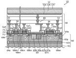
- FIG. 3 is a cross-sectional view schematically showing an example of the device structure of the pixels of the image pickup apparatus according to the first embodiment of the present disclosure.
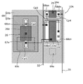
- FIG. 4 is a schematic plan view showing an example of the layout of each element in the pixels of the image pickup apparatus according to the first embodiment of the present disclosure.
- FIG. 5A is a diagram showing the potential of the cutoff structure in the pixels of the image pickup apparatus according to the comparative example.
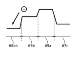
- FIG. 5B is a diagram showing the potential of the cutoff structure in the pixels of the image pickup apparatus according to the first embodiment of the present disclosure.
- FIG. 6 is a diagram showing the impurity concentration dependence of the cutoff structure of the dark current in the pixels of the image pickup apparatus according to the first embodiment of the present disclosure.
- FIG. 7 is a cross-sectional view schematically showing an example of the device structure of the pixels of the image pickup apparatus according to the second embodiment of the present disclosure.
- FIG. 8 is a schematic plan view showing an example of the layout of each element in the pixels of the image pickup apparatus according to the second embodiment of the present disclosure.
- FIG. 9 is a cross-sectional view schematically showing an example of the device structure of the pixels of the image pickup apparatus according to the modified example of the embodiment of the present disclosure.
- the image pickup apparatus includes a photoelectric conversion unit that generates a signal charge by photoelectric conversion, a semiconductor substrate including a first semiconductor layer containing a first conductive type impurity, and a first in the first semiconductor layer.
- a charge storage region that is a two-conducting type impurity region and stores the signal charge, a transistor that includes the second conductive type first impurity region in the first semiconductor layer as one of a source and a drain, and the charge. It is provided with a blocking structure located between the storage region and the first impurity region.
- the blocking structure is a third of the first conductive type in the first semiconductor layer in which the impurity concentration of the first conductive type second impurity region in the first semiconductor layer is different from that of the second impurity region. Includes impurity regions.
- the blocking structure includes a region having a high impurity concentration of the first conductive type between the first impurity region of the second conductive type and the charge storage region, so that the first impurity region of the second conductive type is included. It is possible to accelerate the recombination of minority carriers generated in the pn junction and suppress the inflow of minority carriers into the charge storage region. Therefore, by providing the cutoff structure, it is possible to suppress the dark current flowing in the charge storage region.
- the minority carriers that were not recombined in the first conductive type blocking structure have the property of diffusing in the direction of lowering the impurity concentration. Therefore, it may flow into not only the first impurity region but also the charge storage region.
- the distance between the second impurity region and the charge storage region is the distance between the third impurity region and the charge storage region in a plan view. It may be shorter. Further, for example, the impurity concentration in the second impurity region may be higher than the impurity concentration in the third impurity region.
- the second impurity region functions as a diffusion barrier for the minority carriers generated by the pn junction of the first impurity region. Therefore, it is possible to suppress the inflow of minority carriers into the charge storage region. Therefore, deterioration of the image due to the dark current generated in the charge storage region can be further suppressed.
- the second impurity region may be in direct contact with the third impurity region.
- the first semiconductor layer is adjacent to the second semiconductor layer containing the first conductive type impurities and the second semiconductor layer in a plan view, and the impurity concentration is different from that of the second semiconductor layer. It may include a third semiconductor layer.
- the charge storage region may be included in the third semiconductor layer.
- the first impurity region may be contained in the second semiconductor layer.
- the second impurity region may overlap the boundary between the second semiconductor layer and the third semiconductor layer in a plan view.
- the impurity concentration in the region surrounding the charge storage region can be lowered, the pn junction leak in the charge storage region can be reduced.
- the semiconductor substrate may further include a fourth semiconductor layer containing the second conductive type impurities, and the first semiconductor layer is placed between the photoelectric conversion unit and the fourth semiconductor layer. It may be located.
- the minority carriers generated at the pn junction of the first impurity region are likely to be discharged to the fourth semiconductor layer through the third semiconductor layer having a low impurity concentration. Therefore, the inflow of a small number of carriers into the charge storage region can be suppressed, and the dark current can be further suppressed.
- the impurity concentration of the third semiconductor layer may be lower than the impurity concentration of the second semiconductor layer.
- the impurity concentration of the third semiconductor layer is lowered, so that the pn junction leak in the charge storage region in the third semiconductor layer can be reduced. Therefore, the dark current can be further suppressed.
- At least a part of the second impurity region, at least a part of the third impurity region, or at least a part of the second impurity region and at least a part of the third impurity region may be present. It may be located on the surface of the semiconductor substrate.
- the transistor may include a first gate that is electrically connected to the photoelectric conversion unit.
- the second impurity region may surround the charge storage region.
- the third impurity region may surround the transistor.
- the second impurity region does not have to overlap with the third impurity region.
- all or part of a circuit, unit, device, member or part, or all or part of a functional block in a block diagram is a semiconductor device, a semiconductor integrated circuit (IC), or an LSI (lage scale integration). It may be performed by one or more electronic circuits including.
- the LSI or IC may be integrated on one chip, or may be configured by combining a plurality of chips.
- functional blocks other than the storage element may be integrated on one chip.
- it is called LSI or IC, but the name changes depending on the degree of integration, and it may be called system LSI, VLSI (Very Large Scale Integration), or ULSI (Ultra Large Scale Integration).
- FPGA Field Programmable Gate Array
- Reconfigurable Logic Device which can reconfigure the connection relationship inside the LSI or set up the circuit partition inside the LSI, can also be used for the same purpose.
- circuits, units, devices, members or parts can be performed by software processing.
- the software is recorded on a non-temporary recording medium such as one or more ROMs, optical disks, hard disk drives, etc., and when the software is executed by a processor, the functions identified by the software It is executed by a processor and peripheral devices.
- the system or device may include one or more non-temporary recording media on which the software is recorded, a processor, and the required hardware device, such as an interface.
- the terms “upper” and “lower” do not refer to the upward direction (vertically upward) and the downward direction (vertically downward) in absolute spatial recognition, but are based on the stacking order in the laminated configuration. It is used as a term defined by the relative positional relationship.
- the light receiving side of the image pickup device is referred to as “upper”
- the side opposite to the light receiving side is referred to as “lower”.
- the surface facing the light receiving side of the image pickup apparatus is referred to as the "upper surface”
- the surface facing the light receiving side is referred to as the "lower surface”.
- upper, lower, upper surface and “lower surface” are used only to specify the mutual arrangement between the members, and are intended to limit the posture when the image pickup device is used. do not have. Also, the terms “upper” and “lower” are used not only when the two components are spaced apart from each other and another component exists between the two components, but also when the two components are present. It also applies when the two components are placed in close contact with each other and touch each other. Further, in the present specification, “planar view” means a view from a direction perpendicular to the semiconductor substrate.
- FIG. 1 is a diagram showing an exemplary configuration of an image pickup apparatus according to a first embodiment of the present disclosure.
- the image pickup apparatus 100 shown in FIG. 1 has a plurality of pixels 10 and peripheral circuits 40 formed on the semiconductor substrate 60.
- Each pixel 10 includes a photoelectric conversion unit 12.
- the photoelectric conversion unit 12 receives the incident light to generate positive and negative charges, typically hole-electron pairs.
- the photoelectric conversion unit 12 may be a photoelectric conversion structure including a photoelectric conversion layer arranged above the semiconductor substrate 60, or a photodiode formed on the semiconductor substrate 60.
- the photoelectric conversion unit 12 of each pixel 10 is shown so as to be spatially separated from each other, but this is only for convenience of explanation, and the photoelectric conversion unit 12 of the plurality of pixels 10 is shown. It may be continuously arranged on the semiconductor substrate 60 without being spaced from each other.
- the pixels 10 are arranged in a plurality of rows and columns of m rows and n columns.
- m and n independently represent integers of 1 or more.
- the pixels 10 are arranged on the semiconductor substrate 60, for example, in two dimensions to form an imaging region R1.
- the imaging region R1 may be defined as a region of the semiconductor substrate 60 covered by the photoelectric conversion unit 12.
- the number and arrangement of the pixels 10 are not limited to the illustrated example.
- the number of pixels 10 included in the image pickup apparatus 100 may be one.
- the center of each pixel 10 is located on a grid point of a square grid, but for example, a plurality of pixels so that the center of each pixel 10 is located on a grid point such as a triangular grid or a hexagonal grid. 10 may be arranged.
- the pixels 10 may be arranged one-dimensionally, and in this case, the image pickup apparatus 100 may be used as a line sensor.
- the peripheral circuit 40 includes a vertical scanning circuit 42 and a horizontal signal readout circuit 44. As illustrated in FIG. 1, the peripheral circuit 40 may additionally include a control circuit 46. Further, the peripheral circuit 40 may further include a voltage supply circuit that supplies a predetermined voltage to, for example, the pixel 10. The peripheral circuit 40 may further include a signal processing circuit, an output circuit, and the like. The peripheral circuit 40 is arranged in the peripheral region R2. The peripheral region R2 is a region around the imaging region R1.
- the vertical scanning circuit 42 also called a row scanning circuit, has a connection with an address signal line 34 provided corresponding to each row of the plurality of pixels 10.
- the signal line provided corresponding to each line of the plurality of pixels 10 is not limited to the address signal line 34, and the vertical scanning circuit 42 has a plurality of types of signals for each line of the plurality of pixels 10. Wires can be connected.
- the horizontal signal readout circuit 44 also referred to as a row scanning circuit, has a connection with a vertical signal line 35 provided corresponding to each row of the plurality of pixels 10.
- the control circuit 46 receives command data, a clock, or the like given from the outside of the image pickup device 100, and controls the entire image pickup device 100.
- the control circuit 46 has a timing generator and supplies a drive signal to a vertical scanning circuit 42, a horizontal signal readout circuit 44, a voltage supply circuit, and the like.
- the arrow extending from the control circuit 46 schematically represents the flow of the output signal from the control circuit 46.
- the control circuit 46 may be implemented, for example, by a microcontroller including one or more processors.
- the function of the control circuit 46 may be realized by a combination of a general-purpose processing circuit and software, or may be realized by hardware specialized for such processing.
- FIG. 2 is a schematic diagram schematically showing an exemplary circuit configuration of the image pickup apparatus according to the first embodiment of the present disclosure.
- four pixels 10 arranged in two rows and two columns are represented as representatives in order to avoid complication of the drawing.
- Each of these pixels 10 is an example of the pixel 10 shown in FIG.
- Each of the pixels 10 has a photoelectric conversion unit 12, and includes a signal detection circuit 14 electrically connected to the photoelectric conversion unit 12.
- the photoelectric conversion unit 12 includes a photoelectric conversion layer 12b arranged above the semiconductor substrate 60. That is, here, a stacked image pickup device is exemplified as the image pickup device 100.
- the photoelectric conversion unit 12 of each pixel 10 has a connection with the storage control line 31.
- a predetermined voltage is applied to the storage control line 31.
- a positive voltage for example, about 10 V is applied to the storage control line 31 during the operation of the image pickup apparatus 100. obtain.
- a case where holes are used as signal charges will be illustrated.
- the signal detection circuit 14 includes a signal detection transistor 22, an address transistor 24, and a reset transistor 26.
- the signal detection transistor 22, the address transistor 24 and the reset transistor 26 are typically field effect transistors (FETs) formed on the semiconductor substrate 60 supporting the photoelectric conversion unit 12. : Field Effect Transistor).
- FETs field effect transistors
- the gate of the signal detection transistor 22 is electrically connected to the photoelectric conversion unit 12.
- the charge storage node FD connecting the gate of the signal detection transistor 22 to the photoelectric conversion unit 12 has a function of temporarily holding the charge generated by the photoelectric conversion unit 12.
- holes can be stored as signal charges in the charge storage node FD.
- the charge storage node FD includes an impurity region formed on the semiconductor substrate 60 as a part thereof.
- the drain of the signal detection transistor 22 is connected to a power supply wiring 32 that supplies a power supply voltage VDD of, for example, about 3.3 V to each pixel 10 when the image pickup apparatus 100 is operated, and the source is a vertical signal line 35 via the address transistor 24. Connected to. By receiving the power supply voltage VDD from the drain, the signal detection transistor 22 outputs a signal voltage corresponding to the amount of signal charge stored in the charge storage node FD.
- the address signal line 34 is connected to the gate of the address transistor 24 connected between the signal detection transistor 22 and the vertical signal line 35.
- the vertical scanning circuit 42 applies a row selection signal that controls turning on and off of the address transistor 24 to the address signal line 34. As a result, the output of the signal detection transistor 22 of the selected pixel 10 can be read out to the corresponding vertical signal line 35.
- the arrangement of the address transistor 24 is not limited to the example shown in FIG. 2, and may be between the drain of the signal detection transistor 22 and the power supply wiring 32.
- a load circuit 45 and a column signal processing circuit 47 are connected to each of the vertical signal lines 35.
- the load circuit 45 forms a source follower circuit together with the signal detection transistor 22.
- the column signal processing circuit 47 also called a row signal storage circuit, performs noise suppression signal processing represented by correlated double sampling, analog-to-digital conversion, and the like.
- the horizontal signal reading circuit 44 sequentially reads signals from the plurality of column signal processing circuits 47 to the horizontal common signal line 49.
- the load circuit 45 and the column signal processing circuit 47 may be part of the peripheral circuit 40 described above.
- a reset signal line 36 having a connection with the vertical scanning circuit 42 is connected to the gate of the reset transistor 26.
- the reset signal line 36 is provided for each line of the plurality of pixels 10 in the same manner as the address signal line 34.
- the vertical scanning circuit 42 can select the pixel 10 to be reset in line units by applying a row selection signal to the address signal line 34, and resets the reset signal via the reset signal line 36.
- the reset transistor 26 of the selected row can be switched on and off. When the reset transistor 26 is turned on, the potential of the charge storage node FD is reset.
- one of the drain and source of the reset transistor 26 is connected to the charge storage node FD, and the other of the drain and source is the corresponding one of the feedback lines 53 provided for each row of the plurality of pixels 10. It is connected to one. That is, in this example, the voltage of the feedback line 53 is supplied to the charge storage node FD as the reset voltage for initializing the charge of the photoelectric conversion unit 12.
- the image pickup apparatus 100 has a feedback circuit 16 including an inverting amplifier 50 as a part of the feedback path.
- the inverting amplifier 50 is provided for each row of the plurality of pixels 10, and the feedback line 53 described above is connected to the corresponding output terminal of the plurality of inverting amplifiers 50.
- the inverting amplifier 50 may be part of the peripheral circuit 40 described above.
- the inverting input terminal of the inverting amplifier 50 is connected to the vertical signal line 35 of the corresponding column, and the non-inverting input terminal of the inverting amplifier 50 is connected to the non-inverting input terminal of the inverting amplifier 50 during operation of the image pickup apparatus 100, for example, near 1V or 1V.
- a reference voltage Vref which is a positive voltage, is supplied.
- a feedback path for negatively feeding back the output of the pixel 10 can be formed, and by forming the feedback path, the voltage of the vertical signal line 35 is transferred to the inverting amplifier 50. Converges to the input voltage Vref to the non-inverting input terminal.
- the formation of the feedback path resets the voltage of the charge storage node FD to a voltage such that the voltage of the vertical signal line 35 becomes Vref.
- Vref a voltage of any magnitude within the range of the power supply voltage and the ground can be used.
- FIG. 3 is a cross-sectional view schematically showing an example of the device structure of the pixel 10 of the image pickup apparatus 100 according to the first embodiment of the present disclosure.
- Pixels 10 generally include a semiconductor substrate 60, a photoelectric conversion unit 12 arranged above the semiconductor substrate 60, and a conductive structure 89.
- the photoelectric conversion unit 12 is supported by the interlayer insulating layer 90 that covers the semiconductor substrate 60.
- the conductive structure 89 is arranged inside the interlayer insulating layer 90.
- the interlayer insulating layer 90 includes a plurality of insulating layers.
- the conductive structure 89 includes a part of each of a plurality of wiring layers arranged inside the interlayer insulating layer 90.
- the plurality of wiring layers arranged in the interlayer insulating layer 90 include, for example, a wiring layer having an address signal line 34 and a reset signal line 36 as a part thereof, a vertical signal line 35, a power supply wiring 32, a feedback line 53, and the like. It may include a wiring layer having a part thereof. Needless to say, the number of insulating layers and the number of wiring layers in the interlayer insulating layer 90 are not limited to this example and can be set arbitrarily.
- the photoelectric conversion unit 12 includes a pixel electrode 12a formed on the interlayer insulating layer 90, a counter electrode 12c arranged on the incident side of light, and a photoelectric conversion layer arranged between the pixel electrode 12a and the counter electrode 12c. Includes 12b.
- the photoelectric conversion layer 12b is formed of an organic material or an inorganic material such as amorphous silicon, receives light incident through the counter electrode 12c, and generates positive and negative charges by photoelectric conversion.
- the photoelectric conversion layer 12b is typically formed continuously over a plurality of pixels 10.
- the photoelectric conversion layer 12b is formed in a flat plate shape that covers most of the image pickup region R1 of the semiconductor substrate 60 in a plan view. That is, the photoelectric conversion layer 12b is shared by a plurality of pixels 10.
- the photoelectric conversion unit 12 provided for each pixel 10 includes a portion of the photoelectric conversion layer 12b that is different for each pixel 10.
- the photoelectric conversion layer 12b may include a layer made of an organic material and a layer made of an inorganic material. The photoelectric conversion layer 12b may be provided separately for each pixel 10.
- the counter electrode 12c is a translucent electrode formed of a transparent conductive material such as ITO (Indium Tin Oxide).
- transparent as used herein means that the photoelectric conversion layer 12b transmits at least a part of light having a wavelength that can be absorbed, and it is essential that the light is transmitted over the entire wavelength range of visible light. is not.
- the counter electrode 12c is formed continuously over the plurality of pixels 10, similarly to the photoelectric conversion layer 12b. That is, the counter electrode 12c is shared by the plurality of pixels 10.
- the photoelectric conversion unit 12 provided for each pixel 10 includes a portion of the counter electrode 12c that is different for each pixel 10.
- the counter electrode 12c may be provided separately for each pixel 10.
- the counter electrode 12c has a connection with the above-mentioned storage control line 31.
- the potential of the storage control line 31 is controlled to make the potential of the counter electrode 12c higher than the potential of the pixel electrode 12a, so that the positive and negative charges generated by the photoelectric conversion are positive. Charges can be selectively collected by the pixel electrode 12a.
- the counter electrode 12c By forming the counter electrode 12c in the form of a single layer continuous over the plurality of pixels 10, it becomes possible to collectively apply a predetermined potential to the counter electrodes 12c of the plurality of pixels 10.
- the pixel electrode 12a is an electrode formed of a metal such as aluminum or copper, a metal nitride, or polysilicon to which conductivity is imparted by doping with impurities.
- the pixel electrode 12a is electrically separated from the pixel electrode 12a of the other pixel 10 by being spatially separated from the pixel electrode 12a of the other adjacent pixel 10.
- the conductive structure 89 typically includes a plurality of wirings and plugs formed of a metal such as copper or tungsten, or a metal compound such as metal nitride or metal oxide, and a polysilicon plug. One end of the conductive structure 89 is connected to the pixel electrode 12a. By connecting the other end of the conductive structure 89 to the circuit element formed on the semiconductor substrate 60, the pixel electrode 12a of the photoelectric conversion unit 12 and the circuit on the semiconductor substrate 60 are electrically connected to each other.
- the semiconductor substrate 60 includes a support substrate 61 and one or more semiconductor layers formed on the support substrate 61.
- the semiconductor substrate 60 has an n-type semiconductor layer 62n on the support substrate 61 and a p-type semiconductor layer 65p on the n-type semiconductor layer 62n as one or more semiconductor layers.
- the support substrate 61 and the p-type semiconductor layer 65p are electrically connected to each other by a p-type region 64a having a relatively high impurity concentration.
- the semiconductor substrate 60 has a first surface and a second surface opposite to the first surface.
- the first surface is the surface on the side where light is incident.
- the first surface is the surface on the side where the photoelectric conversion unit 12 is provided, among the plurality of surfaces of the semiconductor substrate 60.
- the "front surface” of the semiconductor substrate 60 corresponds to the first surface
- the "back surface” corresponds to the second surface.
- the surface of the semiconductor substrate 60 on the side where the support substrate 61 is provided is the second surface.
- the support substrate 61 contains first conductive type impurities.
- the first conductive type is the p type.
- a p-type silicon substrate is exemplified as the support substrate 61.
- the p-type impurity contained in the support substrate 61 is, for example, boron.
- the support substrate 61 has a connection with a substrate contact provided outside the imaging region R1, which is not shown in FIG. During the operation of the image pickup apparatus 100, the potentials of the support substrate 61 and the p-type semiconductor layer 65p are controlled via the substrate contacts.
- the n-type semiconductor layer 62n is an example of a fourth semiconductor layer of the p-type semiconductor layer 65p, which contains impurities of the second conductive type different from the first conductive type and is located on the opposite side of the photoelectric conversion unit 12. be.
- the n-type semiconductor layer 62n is located between the p-type semiconductor layer 65p and the support substrate 61.
- the second conductive type is n type.
- the n-type impurity contained in the n-type semiconductor layer 62n is, for example, phosphorus.
- a well contact (not shown) is connected to the n-type semiconductor layer 62n.
- the well contact is provided outside the image pickup region R1, and the potential of the n-type semiconductor layer 62n is controlled to be constant via the well contact during the operation of the image pickup apparatus 100. That is, a fixed potential is applied to the n-type semiconductor layer 62n during the operation of the image pickup apparatus 100.
- the n-type semiconductor layer 62n By providing the n-type semiconductor layer 62n, the inflow of minority carriers from the support substrate 61 or the peripheral circuit 40 into the charge storage region 67n where signal charges are stored is suppressed. That is, by providing the n-type semiconductor layer 62n between the support substrate 61 and the p-type semiconductor layer 65p, it is possible to suppress the dark current flowing in the charge storage region 67n.
- the p-type semiconductor layer 65p is an example of a first semiconductor layer containing first conductive type impurities.
- the p-type semiconductor layer 65p is provided on the side closer to the surface of the semiconductor substrate 60 than the n-type semiconductor layer 62n. Specifically, it is provided in contact with the upper surface of the n-type semiconductor layer 62n.
- Each of the n-type semiconductor layer 62n and the p-type semiconductor layer 65p is typically formed by ion implantation of impurities into the semiconductor film formed by epitaxial growth.
- the impurity concentration of the p-type semiconductor layer 65p is higher than the impurity concentration of the support substrate 61.
- the impurity concentration of the support substrate 61 is, for example, about 10 15 cm -3 .
- the impurity concentration of the p-type semiconductor layer 65p can be, for example, about 10 17 cm -3 .
- a plurality of impurity regions are provided in the p-type semiconductor layer 65p of the semiconductor substrate 60.
- the p-type semiconductor layer 65p is provided with a charge storage region 67n, an impurity region 68an, an impurity region 68bn, an impurity region 68cn, an impurity region 68dn, and an impurity region 68en.
- the p-type semiconductor layer 65p is provided with a cutoff structure 69.
- the blocking structure 69 includes an element separation region 69a and an element separation region 69b. Details of the blocking structure 69 will be described later.
- the charge storage region 67n is a second conductive type impurity region in the p-type semiconductor layer 65p, and is an example of a charge storage region for accumulating signal charges.
- the n-type charge storage region 67n is formed in the vicinity of the surface of the semiconductor substrate 60, and at least a part thereof is located on the surface of the semiconductor substrate 60.
- the charge storage region 67n includes a first region 67a and a second region 67b located within the first region 67a and having a higher impurity concentration than the first region 67a.
- the impurity concentration of the first region 67a is, for example, about 10 17 cm -3
- the impurity concentration of the second region 67b is, for example, about 3 ⁇ 10 18 cm -3 .
- "x" means multiplication.
- An insulating layer is arranged on the surface of the semiconductor substrate 60.
- the main surface of the semiconductor substrate 60 on the photoelectric conversion portion 12 side is covered with the first insulating layer 71, the second insulating layer 72, and the third insulating layer 73.
- the first insulating layer 71 is, for example, a thermal oxide film of silicon.
- the second insulating layer 72 is, for example, a silicon dioxide layer, and the third insulating layer 73 is, for example, a silicon nitride layer.
- the second insulating layer 72 may have a laminated structure including a plurality of insulating layers, and similarly, the third insulating layer 73 may also have a laminated structure including a plurality of insulating layers.
- the laminated structure of the first insulating layer 71, the second insulating layer 72 and the third insulating layer 73 has a contact hole h1 on the second region 67b of the charge storage region 67n.
- the contact plug Cp1 which is a part of the conductive structure 89 is connected to the second region 67b via the contact hole h1, whereby the charge storage region 67n is photoelectrically converted via the conductive structure 89. It is electrically connected to the pixel electrode 12a of the unit 12.
- the signal charge generated by the photoelectric conversion unit 12 is stored in the charge storage region 67n.
- junction capacitance formed by the pn junction between the p-type semiconductor layer 65p as the p-well and the n-type charge storage region 67n has a function as a charge storage region that temporarily holds the signal charge. It can be said that the conductive structure 89 and the n-type charge storage region 67n form at least a part of the above-mentioned charge storage node FD.
- the formation of the second region 67b in the charge storage region 67n is not essential. However, by connecting the contact plug Cp1 to the second region 67b having a relatively high impurity concentration, the effect of reducing the contact resistance can be obtained.
- the above-mentioned signal detection circuit 14 is formed on the semiconductor substrate 60.
- the signal detection circuit 14 in the pixel 10 is electrically separated from the signal detection circuit 14 in the other adjacent pixels 10 by arranging the element separation region 69a and the element separation region 69b between the pixels 10 adjacent to each other. Will be done.
- the reset transistor 26 includes an n-type charge storage region 67n as one of the drain region and the source region, and includes an n-type impurity region 68an as the other of the drain region and the source region.
- the reset transistor 26 further includes a gate electrode 26e on the first insulating layer 71, and a portion of the first insulating layer 71 located between the gate electrode 26e and the semiconductor substrate 60 is a gate insulating film of the reset transistor 26. Functions as.
- the impurity region 68an is formed in the p-type semiconductor layer 65p.
- the contact plug Cp2 is connected to the impurity region 68an via the contact hole h2.
- the contact plug Cp2 is electrically connected to the feedback line 53.
- the p-type semiconductor layer 65p is further provided with an n-type impurity region 68bn, an impurity region 68cn, an impurity region 68dn and an impurity region 68en.
- the impurity region 68bn is an example of the first impurity region.
- the impurity concentrations of the impurity region 68an, the impurity region 68bn, the impurity region 68cn, the impurity region 68dn and the impurity region 68en are higher than the impurity concentration of the first region 67a of the charge storage region 67n.
- the signal detection transistor 22 includes an impurity region 68bn, an impurity region 68cn, and a gate electrode 22e on the first insulating layer 71.
- the impurity region 68bn functions as, for example, the drain region of the signal detection transistor 22
- the impurity region 68cn functions as, for example, the source region of the signal detection transistor 22.
- the gate electrode 22e is connected to the portion of the conductive structure 89 that connects the pixel electrode 12a and the contact plug Cp1 to each other in the layer where the address signal line 34 and the reset signal line 36 are located.
- the conductive structure 89 also has an electrical connection with the gate electrode 22e.
- the gate electrode 22e is an example of a first gate that is electrically connected to the photoelectric conversion unit 12.
- a contact plug Cp3 is connected to the impurity region 68bn via the contact hole h3.
- the power supply wiring 32 described above as a source follower power supply is electrically connected to the contact plug Cp3.
- the power supply wiring 32 is not shown in FIG.
- the address transistor 24 is also formed on the semiconductor substrate 60.
- the address transistor 24 includes an impurity region 68en, an impurity region 68dn, and a gate electrode 24e on the first insulating layer 71.
- the n-type impurity region 68en functions as, for example, the drain region of the address transistor 24, and the n-type impurity region 68dn functions as, for example, the source region of the address transistor 24.
- the portion of the first insulating layer 71 located between the gate electrode 24e and the semiconductor substrate 60 functions as the gate insulating film of the address transistor 24.
- the impurity region 68cn and the impurity region 68en are separately provided in the semiconductor substrate 60 and are electrically connected via wiring, but the present invention is not limited to this.
- the impurity region 68cn and the impurity region 68en may be one continuous diffusion region in the semiconductor substrate 60. That is, the signal detection transistor 22 and the address transistor 24 may share one diffusion region. As a result, the signal detection transistor 22 and the address transistor 24 are electrically connected to each other.
- the contact plug Cp4 is connected to the impurity region 68dn via the contact hole h4.
- the contact plug Cp4 is electrically connected to the vertical signal line 35.
- FIG. 4 is a schematic plan view showing an example of the layout of each element in the pixel 10 of the image pickup apparatus 100 according to the present embodiment.
- the pixel 10 is, for example, a 3 ⁇ m ⁇ 3 ⁇ m square.
- the signal detection transistor 22, the address transistor 24, and the reset transistor 26 are shown so as to appear in one cross section, but this is for convenience of explanation only. Therefore, there may be a portion that does not match between the cross section obtained when the element layout shown in FIG. 4 is cut along a certain line and the cross section shown in FIG.
- the cutoff structure 69 includes an element separation region 69a and an element separation region 69b.
- the element separation region 69a is an example of a second impurity region containing a first conductive type impurity.
- the element separation region 69b is an example of a third impurity region containing a first conductive type impurity.
- the element separation region 69a and the element separation region 69b are formed adjacent to each other in the vicinity of the surface of the semiconductor substrate 60.
- the element separation region 69a and the element separation region 69b are adjacent to each other in a plan view, and at least a part of each is located on the surface of the semiconductor substrate 60.
- the element separation region 69a and the element separation region 69b may not be in contact with each other in a plan view, or may be separated from each other by a predetermined distance.
- the cutoff structure 69 is located between the charge storage region 67n and the signal detection transistor 22. Specifically, in a plan view, at least a part of the cutoff structure 69 is located between the charge storage region 67n and the signal detection transistor 22.
- the element separation region 69a is provided closer to the charge storage region 67n than the element separation region 69b in a plan view. Specifically, the element separation region 69a is provided closer to the reset transistor 26 including the charge storage region 67n as one of the source and the drain than the element separation region 69b.
- A is located between B and C
- B and C means that at least one of a plurality of line segments connecting an arbitrary point in B and an arbitrary point in C is A. Means to pass through.
- A is provided closer to C than B” means that the distance between A and C is shorter than the distance between B and C. That is, in the present embodiment, the distance between the element separation region 69a and the charge storage region 67n is shorter than the distance between the element separation region 69b and the charge storage region 67n.
- the “distance between A and B” means the shortest distance between A and B, that is, the distance between the part of A closest to B and the part of B closest to A.
- an element separation region 69a is arranged around the reset transistor 26.
- An element separation region 69b is arranged around each of the signal detection transistor 22 and the address transistor 24.
- the element separation region 69a and the element separation region 69b are adjacent to each other, and the transistors are electrically separated from each other.
- the element separation region 69a and the element separation region 69b are arranged so as to be separated from the ends of the source and drain of each transistor by about 50 nm.
- the element separation region 69a is not in contact with either the charge storage region 67n or the impurity region 68an.
- the device separation region 69a is formed at a distance of about 50 nm from each of the charge storage region 67n and the impurity region 68an.
- the distance between the element separation region 69a, the charge storage region 67n, and the impurity region 68an may be the same or different from each other.
- the element separation region 69b is not in contact with any of the impurity region 68bn, the impurity region 68cn, the impurity region 68dn, and the impurity region 68en.
- the element separation region 69b is formed, for example, about 50 nm away from each of the impurity region 68bn, the impurity region 68cn, the impurity region 68dn, and the impurity region 68en.
- the intervals between the element separation region 69b and each of the impurity region 68bn, the impurity region 68cn, the impurity region 68dn, and the impurity region 68en may be the same or different from each other.
- the element separation region 69a and the element separation region 69b have different impurity concentrations. Specifically, the impurity concentration in the element separation region 69a is higher than the impurity concentration in the element separation region 69b. Further, the impurity concentration of each of the element separation region 69a and the element separation region 69b is higher than the impurity concentration of the p-type semiconductor layer 65p. For example, the impurity concentration of the element separation region 69b is twice or more or five times or more the impurity concentration of the p-type semiconductor layer 65p. The impurity concentration in the element separation region 69a is 1.2 times or more or 1.5 times or more the impurity concentration in the element separation region 69b.
- the impurity concentration in the element separation region 69a is, for example, about 1.3 ⁇ 10 18 cm -3 .
- the impurity concentration in the element separation region 69b is, for example, about 7 ⁇ 10 17 cm -3 .
- "x" means multiplication.
- the element separation region 69a and the element separation region 69b having different impurity concentrations are arranged between the charge storage region 67n and the impurity region 68bn, respectively.
- the impurity concentration of the element separation region 69a arranged near the reset transistor 26 including the charge storage region 67n as one of the source and drain is higher than the impurity concentration of the element separation region 69b.
- FIGS. 5A and 5B are diagrams showing the potential of the cutoff structure 69 in the pixel 10 of the image pickup apparatus 100 according to the comparative example and the embodiment, respectively. Specifically, FIGS. 5A and 5B show the potential of the charge storage region 67n, the impurity region 68bn, and the blocking structure 69 disposed between them.
- each of the charge storage region 67n and the impurity region 68bn is not in contact with the blocking structure 69, and a part of the p-type semiconductor layer 65p is present between them.
- a part of the p-type semiconductor layer 65p is not shown.
- a part of the p-type semiconductor layer 65p located between the charge storage region 67n and the cutoff structure 69 is also included.
- a part of the p-type semiconductor layer 65p located between the impurity region 68bn and the blocking structure 69 is included in the vicinity of the boundary between the impurity region 68bn and the blocking structure 69.
- the positional relationship between the element separation region 69a and the element separation region 69b is different between FIGS. 5A and 5B.
- the element separation region 69b having a low impurity concentration is located closer to the charge storage region 67n than the element separation region 69a having a high impurity concentration. This has a positional relationship opposite to that of the embodiment shown in FIG. 5B.
- the impurity region 68bn is the drain of the signal detection transistor 22, and a power supply voltage VDD of about 3.3 V is applied. Therefore, in the vicinity of the boundary between the impurity region 68bn and the cutoff structure 69, impact ionization occurs due to a high electric field, and a small number of carriers are generated in the cutoff structure 69. The majority of the minority carriers flow into the impurity region 68bn depending on the direction of the electric field. However, when the power supply voltage VDD exceeds 3 V and the number of generated minority carriers increases, the minority carriers not only flow into the n-type semiconductor layer 62n arranged on the support substrate 61 side of the pn junction, but also the charge storage region 67n. It was found that it also flows into the dark current and increases the dark current.
- the reason why a small number of carriers flow into the charge storage region 67n will be explained by the potential of each region.
- the impurity concentration in the element separation region 69b near the charge storage region 67n is lower than the impurity concentration in the element separation region 69a, the boundary between the impurity region 68bn and the blocking structure 69.
- the minority carriers generated in the vicinity the minority carriers that were not absorbed by the impurity region 68bn have a potential gradient that easily flows not only with respect to the impurity region 68bn but also with the charge storage region 67n due to the direction of the potential. This also applies, for example, when the impurity concentrations in the element separation region 69a and the element separation region 69b are the same.
- the element separation region 69a when the impurity concentration of the element separation region 69a near the charge storage region 67n is higher than the impurity concentration of the element separation region 69b as in the present embodiment, the element separation region 69a is as shown in FIG. 5B. , Serves as a barrier to the spread of minority carriers. Therefore, it becomes difficult for a small number of carriers to flow in the charge storage region 67n, and dark current can be suppressed.
- the impurity concentration in the element separation region 69b can be lowered, the pn junction electric field in the impurity region 68bn can be reduced and the generation of minority carriers itself can be suppressed. .. As a result, the minority carriers flowing into the charge storage region 67n can be further reduced, so that the dark current can be further suppressed.
- FIG. 6 is a diagram showing the impurity concentration dependence of the cutoff structure 69 of the dark current in the pixels of the image pickup apparatus according to the present embodiment.
- the horizontal axis shows the difference in the impurity concentration of the element separation region 69a with respect to the element separation region 69b, and the higher the numerical value, the higher the impurity concentration in the element separation region 69a.
- the dark current decreases as the impurity concentration in the element separation region 69a becomes higher than that in the element separation region 69b.
- the element separation region 69a and the element separation region 69b are both arranged at a predetermined distance of about 50 nm from the drain region and the source region of the transistor. This is because, for example, when the drain region and the source region and the element separation region 69a having a high impurity concentration are in direct contact with each other, the electric field strength in the depletion region of the pn junction increases and the junction leak increases. This is to prevent the depletion layer of the junction and the element separation region 69a from overlapping.
- the element separation region 69b having a low impurity concentration may be closer to the charge storage region 67n than the element separation region 69a having a high impurity concentration.
- the impurity region of the element separation region 69b is low, the junction leakage due to the pn junction between the element separation region 69b and the charge storage region 67n is suppressed. Therefore, when the junction leak in the charge storage region 67n is dominant over the junction leak in the impurity region 68bn, the device separation region 69b having a low impurity concentration is the charge storage region 67n more than the element separation region 69a having a high impurity concentration. It may be possible to suppress the dark current if it is placed closer to.
- the configuration of the first semiconductor layer is different from that in the first embodiment.
- the first semiconductor layer includes two semiconductor layers having different impurity concentrations.
- the differences from the first embodiment will be mainly described, and the common points will be omitted or simplified.
- FIG. 7 is a cross-sectional view schematically showing an example of the device structure of the pixel 10A of the image pickup apparatus according to the present embodiment.
- FIG. 8 is a schematic plan view showing an example of the layout of each element in the pixel 10A of the image pickup apparatus according to the present embodiment.
- the main difference between the pixel 10A shown in FIG. 7 and the pixel 10 shown in FIG. 3 is that the pixel 10A is provided with a p-type semiconductor layer 65pA instead of the p-type semiconductor layer 65p. ..
- the p-type semiconductor layer 65pA is an example of the first semiconductor layer, and includes a p-type semiconductor layer 65ap and a p-type semiconductor layer 65bp.
- the p-type semiconductor layer 65bp is an example of a second semiconductor layer containing first conductive type impurities.
- the p-type semiconductor layer 65bp is provided around the p-type semiconductor layer 65ap.
- the p-type semiconductor layer 65ap is an example of a third semiconductor layer containing first conductive type impurities.
- the p-type semiconductor layer 65ap includes a charge storage region 67n.
- the p-type semiconductor layer 65ap is adjacent to the p-type semiconductor layer 65bp in a plan view.
- the boundary 65c shown in FIGS. 7 and 8 corresponds to a contact portion between the p-type semiconductor layer 65ap and the p-type semiconductor layer 65bp.
- the boundary 65c overlaps with the element separation region 69a in a plan view. Specifically, the boundary 65c is in contact with the element separation region 69a. That is, the element separation region 69a is in contact with both the p-type semiconductor layer 65ap and the p-type semiconductor layer 65bp.
- the impurity concentration of the p-type semiconductor layer 65ap is different from the impurity concentration of the p-type semiconductor layer 65bp. Specifically, the impurity concentration of the p-type semiconductor layer 65ap is lower than the impurity concentration of the p-type semiconductor layer 65bp. As a result, the impurity concentration in the region surrounding the charge storage region 67n can be lowered, so that the pn junction leak in the charge storage region 67n can be reduced.
- the impurity concentration of the p-type semiconductor layer 65ap is, for example, the same as the impurity concentration of the support substrate 61. Further, the impurity concentration of the p-type semiconductor layer 65bp is lower than the impurity concentration of the device separation region 69b.
- the impurity concentration of the p-type semiconductor layer 65bp may be the same as the impurity concentration of the p-type semiconductor layer 65p according to the first embodiment.
- the impurity concentration of the p-type semiconductor layer 65ap is, for example, about 10 16 cm -3 .
- the impurity concentration of the p-type semiconductor layer 65bp is, for example, about 10 17 cm -3 .
- the element separation region 69a and the charge storage region 67n of the cutoff structure 69 are provided at a predetermined distance such as 50 nm in a plan view.
- the charge storage region 67n is surrounded by the p-type semiconductor layer 65ap having a low impurity concentration and is not in contact with the blocking structure 69 having a high impurity concentration.
- each layer and each region is emphasized in FIG. 7, the distance between the element separation region 69a and the n-type semiconductor layer 62n is based on the distance between the element separation region 69a and the charge storage region 67n. short. Therefore, the minority carriers generated by the junction electric field between the impurity region 68bn and the device separation region 69b form the p-type semiconductor layer 65ap before reaching the charge storage region 67n when viewed from a direction horizontal to the semiconductor substrate 60. It is likely to be discharged to the n-type semiconductor layer 62n via the n-type semiconductor layer 62n. Therefore, the dark current can be further reduced.
- the boundary 65c may overlap with the element separation region 69b in a plan view.
- the boundary 65c may be located between the impurity region 68bn and the device separation region 69b in a plan view. That is, the boundary 65c may not overlap the blocking structure 69 in a plan view, and the blocking structure 69 may be in contact with and surrounded only by the p-type semiconductor layer 65ap.
- the dark current can be reduced by reducing the pn junction leak in the charge storage region 67n and improving the discharge property of the minority carriers.
- the boundary 65c overlaps the impurity region 68bn, the pn junction leak may vary between pixels. Therefore, by providing the boundary 65c so as not to overlap the impurity region 68bn, it is possible to suppress variations in electrical characteristics.
- the cutoff structure 69 has an element separation region 69a and an element separation region 69b having different impurity concentrations, but is not limited thereto.
- the element separation region 69a and the element separation region 69b may have the same impurity concentration.
- FIG. 9 is a cross-sectional view schematically showing an example of the device structure of the pixel 10B of the image pickup apparatus according to the present modification.
- the main difference between the pixel 10B shown in FIG. 9 and the pixel 10A shown in FIG. 7 is that the pixel 10B includes the blocking structure 69B instead of the blocking structure 69.
- the blocking structure 69B is composed of one impurity region having a substantially uniform impurity concentration.
- the impurity concentration of the cutoff structure 69B is higher than the impurity concentration of either the p-type semiconductor layer 65ap or the p-type semiconductor layer 65bp.
- the impurity concentration of the blocking structure 69B may be equal to the impurity concentration of the element separation region 69a according to the first and second embodiments, or may be equal to the impurity concentration of the element separation region 69b.
- the impurity concentration of the cutoff structure 69B may be higher than the impurity concentration of the element separation region 69a and lower than the impurity concentration of the element separation region 69b.
- the impurity concentration of the blocking structure 69B is 7 ⁇ 10 17 cm -3 or more and 1.3 ⁇ 10 18 cm -3 or less, but is not limited thereto.
- the cutoff structure 69B and the charge storage region 67n are provided at a predetermined distance of, for example, 50 nm in a plan view.
- the charge storage region 67n is surrounded by the p-type semiconductor layer 65ap having a low impurity concentration and is not in contact with the blocking structure 69B having a high impurity concentration.
- the boundary 65c overlaps the blocking structure 69B in a plan view. Specifically, the boundary 65c is in contact with the blocking structure 69B. That is, the cutoff structure 69B is in contact with both the p-type semiconductor layer 65ap and the p-type semiconductor layer 65bp.
- the distance between the cutoff structure 69B and the n-type semiconductor layer 62n is shorter than the distance between the cutoff structure 69B and the charge storage region 67n. Therefore, the minority carriers generated in the vicinity of the impurity region 68bn are likely to be discharged to the n-type semiconductor layer 62n via the low-concentration p-type semiconductor layer 65ap. Therefore, as in the first embodiment, the minority carriers flowing in the charge storage region 67n can be suppressed and the dark current can be suppressed as compared with the case where the p-type semiconductor layer 65p has a single structure.
- the boundary 65c may be located between the blocking structure 69B and the impurity region 68bn in a plan view, as in the second embodiment. That is, the boundary 65c may not overlap the blocking structure 69B in a plan view, and the blocking structure 69B may be in contact with and surrounded only by the p-type semiconductor layer 65ap. Even in this case, the dark current can be reduced by reducing the pn junction leak in the charge storage region 67n and improving the discharge property of the minority carriers.
- each of the above-mentioned signal detection transistor 22, address transistor 24, and reset transistor 26 may be an N-channel MOSFET or a P-channel MOSFET.
- the first conductive type impurity is a p-type impurity and the second conductive type impurity is an n-type impurity. It is not necessary that all of these transistors are unified into either N-channel MOSFET or P-channel MOSFET.
- the arrangement of the source and the drain in each of these transistors may be exchanged with each other.
- the present disclosure can be used as an image pickup device capable of suppressing dark current, and can be used, for example, as an image sensor mounted on a camera, a surveillance camera, an in-vehicle camera, or the like.
Landscapes
- Solid State Image Pick-Up Elements (AREA)
Priority Applications (3)
| Application Number | Priority Date | Filing Date | Title |
|---|---|---|---|
| JP2022566805A JPWO2022118617A1 (https=) | 2020-12-02 | 2021-11-09 | |
| CN202180076370.1A CN116438659A (zh) | 2020-12-02 | 2021-11-09 | 摄像装置 |
| US18/317,384 US20230290793A1 (en) | 2020-12-02 | 2023-05-15 | Imaging device |
Applications Claiming Priority (2)
| Application Number | Priority Date | Filing Date | Title |
|---|---|---|---|
| JP2020200065 | 2020-12-02 | ||
| JP2020-200065 | 2020-12-02 |
Related Child Applications (1)
| Application Number | Title | Priority Date | Filing Date |
|---|---|---|---|
| US18/317,384 Continuation US20230290793A1 (en) | 2020-12-02 | 2023-05-15 | Imaging device |
Publications (1)
| Publication Number | Publication Date |
|---|---|
| WO2022118617A1 true WO2022118617A1 (ja) | 2022-06-09 |
Family
ID=81853684
Family Applications (1)
| Application Number | Title | Priority Date | Filing Date |
|---|---|---|---|
| PCT/JP2021/041253 Ceased WO2022118617A1 (ja) | 2020-12-02 | 2021-11-09 | 撮像装置 |
Country Status (4)
| Country | Link |
|---|---|
| US (1) | US20230290793A1 (https=) |
| JP (1) | JPWO2022118617A1 (https=) |
| CN (1) | CN116438659A (https=) |
| WO (1) | WO2022118617A1 (https=) |
Cited By (1)
| Publication number | Priority date | Publication date | Assignee | Title |
|---|---|---|---|---|
| WO2026079210A1 (ja) * | 2024-10-08 | 2026-04-16 | ソニーセミコンダクタソリューションズ株式会社 | 光検出装置 |
Citations (5)
| Publication number | Priority date | Publication date | Assignee | Title |
|---|---|---|---|---|
| JP2008078302A (ja) * | 2006-09-20 | 2008-04-03 | Canon Inc | 撮像装置および撮像システム |
| JP2011009354A (ja) * | 2009-06-24 | 2011-01-13 | Canon Inc | 固体撮像装置 |
| JP2019212900A (ja) * | 2018-05-31 | 2019-12-12 | パナソニックIpマネジメント株式会社 | 撮像装置 |
| JP2019212901A (ja) * | 2018-05-31 | 2019-12-12 | パナソニックIpマネジメント株式会社 | 撮像装置 |
| WO2020170658A1 (ja) * | 2019-02-22 | 2020-08-27 | パナソニックIpマネジメント株式会社 | 撮像装置 |
Family Cites Families (1)
| Publication number | Priority date | Publication date | Assignee | Title |
|---|---|---|---|---|
| WO2012147302A1 (ja) * | 2011-04-28 | 2012-11-01 | パナソニック株式会社 | 固体撮像装置及びそれを用いたカメラシステム |
-
2021
- 2021-11-09 WO PCT/JP2021/041253 patent/WO2022118617A1/ja not_active Ceased
- 2021-11-09 CN CN202180076370.1A patent/CN116438659A/zh active Pending
- 2021-11-09 JP JP2022566805A patent/JPWO2022118617A1/ja active Pending
-
2023
- 2023-05-15 US US18/317,384 patent/US20230290793A1/en not_active Abandoned
Patent Citations (5)
| Publication number | Priority date | Publication date | Assignee | Title |
|---|---|---|---|---|
| JP2008078302A (ja) * | 2006-09-20 | 2008-04-03 | Canon Inc | 撮像装置および撮像システム |
| JP2011009354A (ja) * | 2009-06-24 | 2011-01-13 | Canon Inc | 固体撮像装置 |
| JP2019212900A (ja) * | 2018-05-31 | 2019-12-12 | パナソニックIpマネジメント株式会社 | 撮像装置 |
| JP2019212901A (ja) * | 2018-05-31 | 2019-12-12 | パナソニックIpマネジメント株式会社 | 撮像装置 |
| WO2020170658A1 (ja) * | 2019-02-22 | 2020-08-27 | パナソニックIpマネジメント株式会社 | 撮像装置 |
Cited By (1)
| Publication number | Priority date | Publication date | Assignee | Title |
|---|---|---|---|---|
| WO2026079210A1 (ja) * | 2024-10-08 | 2026-04-16 | ソニーセミコンダクタソリューションズ株式会社 | 光検出装置 |
Also Published As
| Publication number | Publication date |
|---|---|
| JPWO2022118617A1 (https=) | 2022-06-09 |
| CN116438659A (zh) | 2023-07-14 |
| US20230290793A1 (en) | 2023-09-14 |
Similar Documents
| Publication | Publication Date | Title |
|---|---|---|
| JP7262078B2 (ja) | 撮像装置 | |
| US12046607B2 (en) | Imaging device | |
| US12349531B2 (en) | Imaging device | |
| US11094734B2 (en) | Imaging device | |
| CN104851896B (zh) | 固态摄像装置及照相机 | |
| JP6689936B2 (ja) | 撮像装置の製造方法 | |
| JP7411893B2 (ja) | 撮像装置 | |
| US20230290793A1 (en) | Imaging device | |
| JP7511187B2 (ja) | 撮像装置 | |
| JP7050111B2 (ja) | 撮像装置 | |
| JP2025112728A (ja) | 撮像装置およびカメラシステム | |
| TWI762629B (zh) | 拍攝裝置 |
Legal Events
| Date | Code | Title | Description |
|---|---|---|---|
| 121 | Ep: the epo has been informed by wipo that ep was designated in this application |
Ref document number: 21900372 Country of ref document: EP Kind code of ref document: A1 |
|
| ENP | Entry into the national phase |
Ref document number: 2022566805 Country of ref document: JP Kind code of ref document: A |
|
| NENP | Non-entry into the national phase |
Ref country code: DE |
|
| 122 | Ep: pct application non-entry in european phase |
Ref document number: 21900372 Country of ref document: EP Kind code of ref document: A1 |