WO2022114151A1 - 気流制御システム - Google Patents
気流制御システム Download PDFInfo
- Publication number
- WO2022114151A1 WO2022114151A1 PCT/JP2021/043487 JP2021043487W WO2022114151A1 WO 2022114151 A1 WO2022114151 A1 WO 2022114151A1 JP 2021043487 W JP2021043487 W JP 2021043487W WO 2022114151 A1 WO2022114151 A1 WO 2022114151A1
- Authority
- WO
- WIPO (PCT)
- Prior art keywords
- airflow
- control system
- intake
- air supply
- target space
- Prior art date
- Legal status (The legal status is an assumption and is not a legal conclusion. Google has not performed a legal analysis and makes no representation as to the accuracy of the status listed.)
- Ceased
Links
Images




Classifications
-
- F—MECHANICAL ENGINEERING; LIGHTING; HEATING; WEAPONS; BLASTING
- F24—HEATING; RANGES; VENTILATING
- F24F—AIR-CONDITIONING; AIR-HUMIDIFICATION; VENTILATION; USE OF AIR CURRENTS FOR SCREENING
- F24F11/00—Control or safety arrangements
- F24F11/70—Control systems characterised by their outputs; Constructional details thereof
- F24F11/72—Control systems characterised by their outputs; Constructional details thereof for controlling the supply of treated air, e.g. its pressure
- F24F11/79—Control systems characterised by their outputs; Constructional details thereof for controlling the supply of treated air, e.g. its pressure for controlling the direction of the supplied air
-
- F—MECHANICAL ENGINEERING; LIGHTING; HEATING; WEAPONS; BLASTING
- F24—HEATING; RANGES; VENTILATING
- F24F—AIR-CONDITIONING; AIR-HUMIDIFICATION; VENTILATION; USE OF AIR CURRENTS FOR SCREENING
- F24F11/00—Control or safety arrangements
- F24F11/70—Control systems characterised by their outputs; Constructional details thereof
- F24F11/72—Control systems characterised by their outputs; Constructional details thereof for controlling the supply of treated air, e.g. its pressure
- F24F11/74—Control systems characterised by their outputs; Constructional details thereof for controlling the supply of treated air, e.g. its pressure for controlling air flow rate or air velocity
-
- F—MECHANICAL ENGINEERING; LIGHTING; HEATING; WEAPONS; BLASTING
- F24—HEATING; RANGES; VENTILATING
- F24F—AIR-CONDITIONING; AIR-HUMIDIFICATION; VENTILATION; USE OF AIR CURRENTS FOR SCREENING
- F24F13/00—Details common to, or for air-conditioning, air-humidification, ventilation or use of air currents for screening
- F24F13/08—Air-flow control members, e.g. louvres, grilles, flaps or guide plates
-
- F—MECHANICAL ENGINEERING; LIGHTING; HEATING; WEAPONS; BLASTING
- F24—HEATING; RANGES; VENTILATING
- F24F—AIR-CONDITIONING; AIR-HUMIDIFICATION; VENTILATION; USE OF AIR CURRENTS FOR SCREENING
- F24F13/00—Details common to, or for air-conditioning, air-humidification, ventilation or use of air currents for screening
- F24F13/08—Air-flow control members, e.g. louvres, grilles, flaps or guide plates
- F24F13/081—Air-flow control members, e.g. louvres, grilles, flaps or guide plates for guiding air around a curve
-
- F—MECHANICAL ENGINEERING; LIGHTING; HEATING; WEAPONS; BLASTING
- F24—HEATING; RANGES; VENTILATING
- F24F—AIR-CONDITIONING; AIR-HUMIDIFICATION; VENTILATION; USE OF AIR CURRENTS FOR SCREENING
- F24F7/00—Ventilation
- F24F7/003—Ventilation in combination with air cleaning
-
- F—MECHANICAL ENGINEERING; LIGHTING; HEATING; WEAPONS; BLASTING
- F24—HEATING; RANGES; VENTILATING
- F24F—AIR-CONDITIONING; AIR-HUMIDIFICATION; VENTILATION; USE OF AIR CURRENTS FOR SCREENING
- F24F7/00—Ventilation
- F24F7/04—Ventilation with ducting systems, e.g. by double walls; with natural circulation
- F24F7/06—Ventilation with ducting systems, e.g. by double walls; with natural circulation with forced air circulation, e.g. by fan positioning of a ventilator in or against a conduit
- F24F7/10—Ventilation with ducting systems, e.g. by double walls; with natural circulation with forced air circulation, e.g. by fan positioning of a ventilator in or against a conduit with air supply, or exhaust, through perforated wall, floor or ceiling
-
- F—MECHANICAL ENGINEERING; LIGHTING; HEATING; WEAPONS; BLASTING
- F24—HEATING; RANGES; VENTILATING
- F24F—AIR-CONDITIONING; AIR-HUMIDIFICATION; VENTILATION; USE OF AIR CURRENTS FOR SCREENING
- F24F8/00—Treatment, e.g. purification, of air supplied to human living or working spaces otherwise than by heating, cooling, humidifying or drying
- F24F8/10—Treatment, e.g. purification, of air supplied to human living or working spaces otherwise than by heating, cooling, humidifying or drying by separation, e.g. by filtering
- F24F8/108—Treatment, e.g. purification, of air supplied to human living or working spaces otherwise than by heating, cooling, humidifying or drying by separation, e.g. by filtering using dry filter elements
Definitions
- the present application relates to the field of indoor air conditioning, and particularly to an airflow control system for controlling an airflow in a target space in a certain range.
- the air purification system is a general indoor air conditioning system for circulating air in a closed or semi-closed indoor space to purify the air in the indoor space.
- a typical air purifier is usually placed on the ground, sending air through an air outlet located at the top or top of the air purifier, taking in air from the side near the ground, and constantly circulating the air in the room. It purifies the air in the room.
- a blowing method and an intake method stir all the air in the room, and the contaminants are diffused throughout the room.
- the fresh air system in a commercial office building has many air inlets and can be distributed in different locations, but usually there are only one or two centralized return ports on each floor and air containing contaminants. Passes through different stations and finally reaches the centralized return port.
- This application is made to solve the above-mentioned problems existing in the prior art, and controls the flow of airflow in the indoor space, suppresses the diffusion of the pollutants existing there, and further spreads the pollutants to the local area.
- the purpose is to provide an airflow control system with improved structure that can be shut off and discharged from the indoor space.
- the airflow control system for controlling an airflow direction in a target space including a top and a bottom.
- the airflow control system includes at least one airflow guide assembly, the airflow guide assembly including an air outlet located at the top of the target space and at least blowing transport airflow through the air outlet into the target space.
- It includes one air supply device and at least one intake device that includes an intake port located at the bottom of the target space and sucks air from the target space through the intake port.
- the blown airflow blown out from the at least one air supply device and the suction force of the at least one intake device cooperate with each other to generate an induced airflow from top to bottom, and pollutants in the target space. Is located in the flow path of the guided airflow, so that the induced airflow can suppress the upward diffusion of contaminants existing in the target space.
- the air supply port of the air supply device is located at the top of the target space, so that the air blown air from the air supply port flows from substantially above to the bottom, and the air intake device is located at the bottom of the target space.
- the intake port is provided, and the blown airflow and the suction force formed by the intake device cooperate with each other to form an induced airflow from top to bottom, and the action of the induced airflow causes the upward diffusion of contaminants. And by sucking contaminants downward into the inspiratory system, the risk of cross-infection in obstructed or semi-occluded spaces can be avoided.
- the wind speed of the blown airflow is smaller than the wind speed of the intake airflow formed by the action of the intake device. Since the flow velocity of the blown airflow is small, there is no obvious feeling of air supply to the person in the target space, and the comfort is improved.
- the blowout airflow is set so that the wind speed at the air supply port is 0.6 m / s or less so as to be selectable. Such a wind speed setting can effectively reduce the eddy current formed near the boundary between the blown airflow and the guided airflow, and further helps to suppress the diffusion of pollutants.
- the central axis of at least one intake device and the central axis of at least one air supply device are offset from each other.
- the airflow guide assembly can include any suitable number of air feeders and any suitable number of intake devices as needed.
- the airflow guide assembly includes one air supply device and one intake device, and the intake device and the air supply device are optionally provided with their central axes displaced or overlapped with each other.
- the airflow guide assembly may include two inspiratory devices and one inspiratory device such that each has one inspiratory device on each side of the inspiratory device.
- the airflow guide assembly may include one intake device and four air supply devices provided on at least both sides of the intake device.
- the airflow guide assembly may include one air supply device and two air intake devices so that each has one air intake device on each side of the air supply device.
- the airflow guide assembly may include one air supply device and four air intake devices provided on at least both sides of the air supply device.
- the air supply device is located outside the range of projection at the top by the obstacle, and the intake device is located within the range of projection at the bottom by the obstacle.
- the blown airflow from the air blower does not hit the obstacle and can further reduce the eddy current generated by the blown airflow, which further helps to reduce the diffusion of contaminants.
- the air supply port of the air supply device blows out the blown airflow substantially vertically.
- the airflow control system further includes an exhaust device that exhausts the airflow with contaminants sucked into the intake device to the external environment.
- the airflow control system is provided in the target space and further includes an air treatment device for processing the airflow sucked from the target space.
- the air treatment device can include a purification assembly for purifying the air flow.
- the purification assembly may include a filtration member, or the purification assembly itself is a filtration member.
- the intake device is provided with an active suction member, which helps to achieve the required and appropriate intake wind speed.
- an induced airflow that moves from substantially above to below is formed in the target space in cooperation with the blown airflow of the air supply device and the suction force of the intake device, and is guided.
- the contaminants located in the flow path are also moved so as to flow substantially downward, thereby suppressing the tendency of the upward diffusion of the contaminants and allowing the contaminants to flow as quickly as possible. To reduce further contamination due to diffusion of contaminants in the target space.
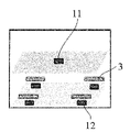
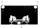
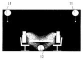
- FIG. 1 It is a schematic diagram of the exemplary airflow control system implemented in the target space according to the present invention. It is a schematic diagram of the airflow mode formed by the airflow control system in FIG. It is a schematic diagram of the preferable structure of the airflow control system of FIG. This is the first example of the arrangement form of the air supply device and the intake device. This is the second example of the arrangement of the air supply device and the intake device. This is the third example of the arrangement form of the air supply device and the intake device. This is the fourth example of the arrangement form of the air supply device and the intake device.
- the "target space” refers to a space in which a person is active and an obstacle (for example, a table, a cabinet) is placed.
- the “top and bottom of the target space” refers to the boundary surface above the target space and the boundary surface below the target space.
- top space above the target space refers to a space that is located above the target space, but is separated from the target space and partially communicates with it.
- the "bottom space” below the target space refers to a space that is located below the target space, but is separated from the target space and partially communicates with it.
- Wind speed of blown airflow refers to the wind speed at the air outlet of the air supply device.
- Wind speed of intake airflow refers to the wind speed at the intake port of the intake device.
- the ceiling at the top of the target space is provided for air supply, and the floor at the bottom of the target space is provided at the return air inlet (perforated board floor).
- the airflow that is blown out suppresses the diffusion of contaminants, and the downward airflow moves away from the target space through the nearby return air inlet on the floor.
- the entire cleanroom system is expensive, complex to implement, and has high running costs. Further, in a clean room provided in this way, it is usually necessary to eliminate or reduce obstacles (for example, a table) in order to reduce the influence of obstacles on the airflow structure.
- the air supply port is provided at the top of the target space and the intake port is provided at the bottom of the target space.
- a guided airflow from substantially above to the bottom is formed in the target space, thereby moving the guided airflow downward. Suppresses the tendency of upward diffusion of contaminants in.
- the airflow control system provides an exhaust device that exhausts air containing contaminants taken into the return air device out of the target space to maintain the cleanliness of the air in the target space. Further included.
- the return air device and / or the air supply device is provided with a filtration member to purify the return air and / or the air supply, and to clean the exhaust and / or the air supply. Secure the degree.
- the airflow control system further comprises an air treatment device, the air containing contaminants sucked by the return air device is transmitted to the air treatment device, and the air treatment device is provided with a purification assembly. And realize the purification treatment of pollutants.
- the purification assembly includes, for example, a filtration member, or the purification assembly itself is a filtration member. The treated air is sent back into the target space via the air supply device to realize the internal circulation of the air in the space.
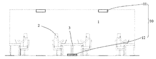
- FIG. 1 shows a schematic diagram of an exemplary airflow control system 10 of the present invention mounted in the target space 1.
- the target space 1 is, for example, an indoor office, which is usually closed or semi-closed, and is relatively crowded with personnel.
- furniture such as a desk 3 that constitutes an obstacle to the flow of airflow is placed.
- office staff 2 who usually sits in front of the desk 3.
- the target space 1 in order to suppress the diffusion of contaminants (for example, dust, pathogens, etc.) in the local region of the target space 1 in the target space 1, the target space 1 is provided with an air flow in the target space 1.
- An airflow control system 10 that can be controlled is provided.
- the airflow control system 10 includes an air supply device 11 that is located above the target space 1 and generally includes an air supply port formed at the top of the target space 1.
- the air supply port of the air supply device 11 can be provided on the ceiling of the target space 1.
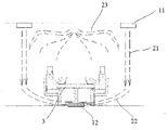
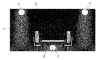
- the air supply device 11 blows out the blown airflow 21 to the target space 1 through the air supply port (see FIG. 2), and the blown airflow 21 becomes a substantially vertical airflow from top to bottom.
- the blowout airflow 21 may have a constant blowout angle, for example, may be inclined toward a worker on one side, but the inclination angle of the blowout airflow 21 is set in order to avoid the formation of a vortex. It is such that the blown airflow 21 does not act directly on the worker.
- the airflow control system 10 is located below the target space 1 and further includes an intake device 12 including an intake port provided at the bottom (for example, the floor) of the target space 1.
- the intake device 12 sucks air from the target space 1 through the intake port to form an intake air flow 22 (see FIG. 2).
- the air supply device 11 blows out the blown airflow 21 substantially vertically downward, and the suction action of the intake device 12 is such that the intake airflow 22 is formed in the vicinity thereof, and the intake airflow 22 forms the intake airflow 22 in the target space 1.
- the airflow including the blowout airflow 21 flows to the intake port of the intake device 12.
- the intake airflow 22 generated by the intake device 12 further forms an guided airflow 23 in the target space 1 together with the blown airflow 21, and the guided airflow 23 basically forms a flow path from top to bottom. Then, the contaminants in the region where the guided airflow 23 flows are taken away together, the diffusion of the contaminants is prevented, and finally the contaminants are sucked into the intake device 12.
- the desk 3 is located in a region of the guided airflow 23, so that the office staff 2 sitting in front of the desk 3 is also in the region of the guided airflow 23, but the blown airflow 21. Since the intake airflow 22 is outside the region of the induced airflow 23, the blown airflow 21 does not come into direct contact with the office staff 2, so that the office staff 2 does not feel a clear wind feeling and is comfortable for the human body. Sex improves. Further, the office staff 2 and the desk 3 are outside the range of the blown airflow 21, and the blown airflow 21 suppresses the diffusion of contaminants in the target space 1 without causing a vortex due to collision or contact with them. More useful to do.
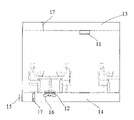
- FIG. 3 shows a preferred exemplary structure of the airflow control system 10.
- the airflow control system 10 includes an air supply device 11 located above the target space 1 and an intake device 12 located below the target space 1.
- the airflow control system 10 further includes an air supply passage 13 that communicates with the air supply device 11 and supplies air to the air supply device 11.
- the air supply passage 13 is formed above the target space 1.
- an air duct that is connected to the air supply device 11 and communicates with each other can be provided.
- another form of the air supply passage 13 is a top space partitioned by a ceiling above the target space 1. At this time, the air supply device 11 communicates the fluid with the top space.
- the air supply passage 13 by using the top space partitioned by the ceiling as the air supply passage 13, it is possible to reduce the difficulty and cost of mounting the entire system, and the air supply passage does not require the arrangement of an air duct, and the air duct does not need to be arranged. There are few changes to the ceiling, and the air supply device can be mounted by removing the ceiling a little, and the mounting cost is low.
- the airflow control system 10 can further include a return air passage 14 formed below the target space 1 that communicates with the intake device 12.
- a return air passage 14 may be an air duct provided below the target space 1, or may be a bottom space partitioned by a floor at the bottom of the target space 1.
- the return air passage 14 does not require the arrangement of an air duct and is basically. There is no need to consider avoiding the pipelines and lines that originally existed in the space under the floor, there are few changes to the floor, and the floor can be removed a little and replaced with an intake device.
- An exhaust device 15 for discharging the air flow with contaminants sucked from the target space 1 by the intake device 12 to the external environment can be further provided in the bottom space.
- the exhaust device 15 can be further provided in the target space or in the top space, and the air flow with contaminants in the return air passage 14 is sent to the exhaust device 15 via the air duct. It is transmitted and finally discharged to the external environment.
- an airflow passage module (not shown) can be provided between the air supply device 11 and the intake device 12.
- the lower end of the airflow passage is connected to the return air passage 14, and the upper end is connected to the air supply passage 13.
- the airflow sucked by the intake device 12 is returned to the air supply device 11 via the airflow passage module, and is blown out to the target space 1 again by the air supply device 11 to form the blowout airflow 21.
- a filtration member 17 for purifying the air forming the airflow can be provided upstream of the air supply device 11, for example, in the air supply passage 13. .
- an air treatment device is provided between the air supply device 11 and the intake device 12.
- the air treatment device is preferably provided in the return air passage 14 and upstream of the exhaust device 15.
- the air treatment device can include a purification assembly for purifying the airflow.
- the purification assembly can include a filtration member 17 similar to the above, or the purification assembly itself is a filtration member 17.
- the airflow treated by the air treatment device can be returned to the air supply passage 13 and is blown back to the target space 1 to realize that the airflow is internally circulated in the target space 1. .. Further, in a further alternative embodiment, at least a part of the air treatment device can be provided in the target space 1, and preferably, the air in the target space 1 is directly purified by sucking the air flow from the lower part of the target space 1. An air treatment device is provided so as to do so.
- the intake device 12 may be provided with an active suction member 16, the form of which is, for example, a fan schematically shown in the figure.
- the active suction member 16 can realize a suction airflow having a constant wind speed, which is advantageous in cooperating with the air supply airflow to effectively form an induced airflow from substantially above to below.
- an appropriate number of air supply devices 11 and an appropriate number of intake devices 12 can be combined to form one airflow guide assembly. can. Some exemplary arrangements will be described below.
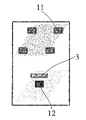
- FIG. 4 shows the first example of the arrangement form of the air supply device 11 and the intake device 12.
- a set is composed of one air supply device 11 and one intake device 12, and one airflow guide assembly is formed.
- the projection and intake device 12 at the bottom of the target space 1 by the air supply device 11 is located on the same side of the desk 3, and has the central axis of the air supply device 11 and the central axis of the intake device 12. Are aligned with each other.
- FIG. 5 shows a second example of the arrangement form of the air supply device 11 and the intake device 12.
- a set is composed of one air supply device 11 and one intake device 12, and the projection at the bottom of the target space 1 by the air supply device 11 is located on one side of the desk 3, but the intake device 12 is.
- the central axis of the air supply device 11 and the central axis of the intake device 12 are offset from each other.
- the airflow guide assembly includes two air supply devices 11 and one intake device 12.
- the projections at the bottom of the target space 1 by the two air supply devices 11 are located on both sides of the desk 3, respectively, or those projections are not on the desk 3 and the intake device 12 is located below the desk 3.
- the central axis of each air supply device 11 and the central axis of the intake device 12 are displaced from each other, and the contaminants in the space on both sides of the desk 3 can be treated correspondingly.
- one air supply device 11 and two intake devices 12 are included.
- two desks 3 are arranged in the corresponding target space 1, and the two intake devices 12 are located below the two desks 3, respectively, but the projection at the bottom of the target space 1 by the air supply device 11 is , Located between these two desks 3. Therefore, in the arrangement mode, the central axis of the air supply device 11 and the central axis of the two intake devices 12 are deviated from each other.
- a built-in air-conditioning terminal device that supplies air in both directions can be used as the air supply device 11. In this way, it is compatible with the original air conditioning system and can further reduce the difficulty of implementing the airflow control system.
- one air supply device 11 and four intake devices 12 are included.
- four desks 3 are arranged in the corresponding target space 1
- the four intake devices 12 are located below the four desks 3, respectively
- the projection at the bottom of the target space 1 by the air supply device 11 is It is located in the gap between the four desks 3.
- the central axis of the air supply device 11 and the central axis of the four intake devices 12 are deviated from each other.
- the air supply device 11 a built-in air-conditioning terminal device that supplies air around can be used as the air supply device 11. In this way, it is compatible with the original air conditioning system and can further reduce the difficulty of implementing the airflow control system.
- the airflow control system 10 applied to a particular target space 1 may include one airflow guide assembly thus defined, or may include two, three or more such airflow guide assemblies.
- the specific number is determined based on factors such as the area of the target space 1, the number of offices, and the number of office staff at the design stage.
- control parameters for each direction of the airflow control system 10 according to the present invention will be described.
- the intake airflow 22 is formed by the suction action of the intake device 12, and the intake airflow 22 plays a major role in the process of forming the induction airflow 23.
- the wind speed of the intake airflow 22 is preferably higher than that of the blowout airflow 21.
- CO 2 is used to simulate the contaminants.
- FIG. 10 shows a CO 2 concentration distribution map in the target space 1 obtained in Experiment 1.
- the experiment 1 uses the arrangement of the air supply device 11 and the intake device 12 shown in FIG. 6, that is, the projections at the bottom of the target space 1 by the two air supply devices 11 are located on both sides of the desk 3, respectively.
- the intake device 12 is located below the desk 3, and the intake port of the intake device 12 is assumed to be a square having a size of 300 mm ⁇ 300 mm.
- the wind speed of the blown airflow 21 of the air supply device 11 is set to about 0.3 m / s
- the wind speed of the intake airflow 22 of the intake device 12 is set to about 2.1 m / s.
- the formed airflow pattern is a guided airflow from top to bottom so as to suppress the tendency of the upward diffusion of the discharged gas from the office staff 2 as shown in FIG. It can be seen that 23 can be basically formed.
- the size of the intake port of the intake device 12 is 200 mm ⁇ 200 mm
- the wind speed of the blow air flow 21 of the air supply device 11 is set to about 0.5 m / s
- the intake air flow is set to about 0.5 m / s.
- the wind speed of 22 is set to 2.9 m / s, and it can be seen that the induced airflow 23 formed at this time can effectively block the discharged gas from the office staff 2.
- the wind speed of the intake airflow 22 is set to 1.9 m / s
- the wind speed of the blowout airflow 21 is set to 1 m / s at the air supply port.
- the overall effect of airflow suppression is slightly inferior to that of Experiment 1 and Experiment 2, and in summary, the air supply device 11 is the air supply port.
- the wind speed of the blown airflow 21 is preferably 1 m / s or less, the control effect of the formed induced airflow on the contaminants is better, and the contaminants can be controlled within a narrower range.
- the wind speed of the intake airflow 22 is set to 0.5 m / s, and the wind speed at the air supply port of the blowout airflow 21 is increased to 0.8 m / s.
- the wind speed of the intake airflow 22 is set to 0.5 m / s, and the wind speed at the air supply port of the blowout airflow 21 is increased to 0.8 m / s.
- the power consumption can be reduced on the premise that the effect of suppressing the diffusion of the induced airflow 23 to the pollutants is maintained and further improved by the following method.
- the number of intake ports can be increased, and a plurality of intake ports can be provided so as to be separated from each other.
- the area of each of the multiple intake ports is reduced and the wind speed at each intake port is appropriately reduced as compared with the case where there is only one intake port. By doing so, the total required air volume is lowered as a whole, and the purpose of reducing power consumption is realized.
- the intake port is provided in a rectangular, elliptical or similar long shape, and the long side of the long shape faces the position of the projection at the bottom of the target space 1 by the corresponding air supply device 11. Let me. With the intake port provided in this way, the long side can accommodate the office staff sitting next to the obstacle and better inhale the contaminants discharged from the office staff.
- the intake device 12 includes one square intake port at this time.
- the required intake volume is 700 m 3 / h in order to control the contaminants in the corresponding target space 1.
- Experiment 5 (not shown), the total intake area is the same as in Experiment 1, but two rectangular intake ports are provided that are separated from each other, in order to suppress contaminants in the corresponding target space 1.
- the required intake amount is 520 m 3 / h (the intake amount of each intake port is 260 m 3 / h).
- Table 1 A comparison of the experimental data of Experiment 1 and Experiment 5 is shown in Table 1 below.
Landscapes
- Engineering & Computer Science (AREA)
- Chemical & Material Sciences (AREA)
- Combustion & Propulsion (AREA)
- Mechanical Engineering (AREA)
- General Engineering & Computer Science (AREA)
- Physics & Mathematics (AREA)
- Fluid Mechanics (AREA)
- Ventilation (AREA)
- Air Conditioning Control Device (AREA)
Abstract
頂部と底部とを含む目標空間における気流方向を制御するための気流制御システムである。該気流制御システムの気流ガイドアセンブリは、目標空間の頂部に位置する送気口を含む送気装置と、目標空間の底部に位置する吸気口を含む吸気装置と、を含む。送気装置から吹き出された吹出気流と吸気装置の吸引力とが互いに協働して、上から下への誘導気流が発生する。誘導気流は、目標空間に存在する汚染物の上向きの拡散を抑制できる。該気流制御システムは、汚染物の上向きの拡散を抑制することにより、交差感染のリスクを避けることができる。
Description
本願は、室内空調の分野に関し、特に一定範囲の目標空間における気流を制御するための気流制御システムに関する。
空気浄化システムは、閉塞または半閉塞された室内空間に空気を循環させて、該室内空間の空気に対する浄化を実現するための一般的な室内空調システムである。
一般的な空気清浄機は、通常地面に置かれ、空気清浄機の上部または頂部に位置する送気口から送気し、地面に近い側辺から吸気し、室内の空気を絶えずに循環処理することで室内の空気を浄化する。しかしながら、このような吹出し方と吸気方は、室内の空気を全部かき混ぜ、汚染物が部屋全体に拡散してしまう。業務用オフィスビルの中の新気システムは、送気口が多く、異なる位置に分布することができるが、通常、各階には一つから二つの集中還気口しかなく、汚染物を含む空気は、異なるステーションを通過して、最終的に集中還気口に到達する。飛沫やエアロゾルの形で伝播する呼吸器感染症の病原体(例えば、インフルエンザウイルス、新型コロナウイルスなど)について、上述した形態の空気浄化システムの汚染防止効果は、限られ、空気浄化システムは、気流循環によって室内空間における病原体の濃度を下げることはできるが、室内空間での病原体の拡散を完全になくすことはできず、ひいては、空気浄化システムが室内空間に吹き込む気流により病原体に対して拡散作用を果たし、病気の伝播リスクを高めてしまう。
そのため、室内空間における気流を制御でき、該空間の局所領域に存在する、例えば粉塵や病原体などの汚染物が周囲に拡散するのを防止することによって、汚染物を遮断する役割を果たす構造を改良するシステムが求められている。
本願は、以上の従来技術に存在する問題を解決するためになされたもので、室内空間における気流の流れを制御し、そこに存在する汚染物の拡散を抑制し、さらに汚染物を局部領域に遮断して室内空間から排出することができる、構造を改良する気流制御システムを提供することを目的としている。
本願の上述目的は、頂部と底部とを含む目標空間における気流方向を制御するための気流制御システムにより実現される。ここに、気流制御システムは、少なくとも一つの気流ガイドアセンブリを含み、該気流ガイドアセンブリは、目標空間の頂部に位置する送気口を含み、送気口を介して目標空間へ輸送気流を吹き出す少なくとも一つの送気装置と、目標空間の底部に位置する吸気口を含み、吸気口を介して目標空間から空気を吸引する少なくとも一つの吸気装置と、を含む。ここに、該少なくとも一つの送気装置から吹き出された吹出気流と該少なくとも一つの吸気装置の吸引力とが互いに協働して、上から下への誘導気流を発生させ、目標空間における汚染物が誘導気流の流動経路に位置することにより、誘導気流により目標空間に存在する汚染物の上向きの拡散を抑制することができる。
上述した構造の気流制御システムにより、送気装置の送気口は、目標空間の頂部に位置することで、送気口からの吹出気流が略上から下へ流れ、目標空間の底部に吸気装置の吸気口が設けられ、該吹出気流と吸気装置で形成された吸引力とが互いに協働し、上から下への誘導気流が形成され、該誘導気流の作用で、汚染物の上向きの拡散を抑制することができるとともに、汚染物を下向きに吸気装置に吸引することによって、閉塞または半閉塞空間での交差感染のリスクを避けることができる。
好ましくは、吹出気流の風速は、吸気装置による作用で形成された吸気気流の風速よりも小さい。吹出気流の流速が小さいため、目標空間にいる人には明らかな送気感がなく、快適性が向上する。選択可能に、吹出気流は、送気口での風速が0.6m/s以下となるように設定される。このような風速の設定は、吹出気流と誘導気流の境界の近傍に形成された渦流を効果的に低減でき、汚染物の拡散を抑制するのにさらに役立つ。
好ましくは、少なくとも一つの吸気装置の中心軸線と少なくとも一つの送気装置の中心軸線とは、互いにずれる。
気流ガイドアセンブリは、必要に応じて任意の適切な数の送気装置と任意の適切な数の吸気装置とを含むことができる。
例えば、一例では、気流ガイドアセンブリは、一つの送気装置と一つの吸気装置とを含み、選択可能に、吸気装置と送気装置は、中心軸線が互いにずれたり重なったりして設けられる。
または、気流ガイドアセンブリは、吸気装置の両側にそれぞれ一つの送気装置を有するように、二つの送気装置と一つの吸気装置とを含んでもよい。
または、気流ガイドアセンブリは、一つの吸気装置と、吸気装置の少なくとも両側に設けられる四つの送気装置とを含んでもよい。
または、気流ガイドアセンブリは、送気装置の両側にそれぞれ一つの吸気装置を有するように、一つの送気装置と二つの吸気装置とを含んでもよい。
または、気流ガイドアセンブリは、一つの送気装置と、送気装置の少なくとも両側に設けられる四つの吸気装置とを含んでもよい。
一般的には、目標空間に障害物が存在し、例えば、オフィスとして使用される目標空間には、デスクなどが置かれる。ここに、送気装置は、障害物による頂部における投影の範囲の外に位置し、吸気装置は、障害物による底部における投影の範囲内に位置する。このように、送気装置からの吹出気流は、障害物に当たることがなく、吹出気流によって発生する渦流をさらに低減することができ、汚染物の拡散を低減するのにさらに役立つ。
好ましくは、送気装置の送気口は、吹出気流を略垂直に吹き出す。
好ましい構造では、気流制御システムは、吸気装置に吸引された汚染物付きの気流を外部環境に排出する排気装置をさらに含む。
好ましくは、気流制御システムは、目標空間に設けられ、前記目標空間から吸引された気流を処理するための空気処理装置をさらに含む。
ここに、前記空気処理装置は、気流を浄化するための浄化アセンブリを含むことができる。該浄化アセンブリは、濾過部材を含んでもよく、または、該浄化アセンブリ自体は、濾過部材である。
好ましくは、吸気装置には、アクティブ吸引部材が設けられ、該アクティブ吸引部材は必要かつ適切な吸気風速を実現するのに役立つ。
本発明の具体的な実施形態に係る気流制御システムは、送気装置の吹出気流と吸気装置の吸引力との協働で、目標空間内で略上から下へ動く誘導気流が形成され、誘導気流は、吸気装置へ流れる経路では、その流動経路に位置する汚染物も略下向きへ流れるように移動させることによって、汚染物の上向きの拡散の傾向を抑制するとともに、汚染物がなるべく速く吸気装置に吸い取られるようにし、汚染物の目標空間での拡散によるさらなる汚染を低減する。
本願の非限定的な好ましい実施構造を添付図面に示し、添付図面と組み合わせることで、本願の特徴と利点をより明らかにすることができる。
本発明に係る目標空間に実装された例示的な気流制御システムの模式図である。
図1における気流制御システムにより形成された気流モードの模式図である。
図1の気流制御システムの好ましい構造の模式図である。
送気装置と吸気装置の配置形態の第一の例である。
送気装置と吸気装置の配置形態の第二の例である。
送気装置と吸気装置の配置形態の第三の例である。
送気装置と吸気装置の配置形態の第四の例である。
送気装置と吸気装置の配置形態の第五の例である。
送気装置と吸気装置の配置形態の第六の例である。
実験1で得られた目標空間におけるCO2濃度分布図(シミュレーション図)である。
図10に示す実験1で得られた気流パターンの模式図である。
実験2で得られた目標空間におけるCO2濃度分布図(シミュレーション図)である。
実験3で得られた目標空間におけるCO2濃度分布図(シミュレーション図)である。
実験4で得られた目標空間におけるCO2濃度分布図(シミュレーション図)である。
本発明を理解しやすくするために、本発明の具体的な実施例について添付図面を参照して以下に説明する。しかし、添付図面に示されているのは、本発明の好ましい実施例に過ぎず、本発明の範囲を制限するものではないことが理解されるべきである。当業者であれば、添付図面に示された実施例に基づいて、本発明に対してさまざまな自明な補正、変形、および等価置換を行うことができ、矛盾しない限り、異なる実施例における構成要件を任意に組み合わせることができ、これらは、本発明の保護範囲内にある。
以下、本発明の具体的な実施形態についての説明において、「目標空間」とは、人が活動し、障害物(例えば、テーブル、キャビネット)などが置かれている空間を指す。「目標空間の頂部と底部」とは、目標空間の上方の境界面と目標空間の下方の境界面を指す。
目標空間の上方の「頂部空間」とは、目標空間の上方に位置するが、目標空間と分離され、かつ一部連通している空間を指す。
目標空間の下方の「底部空間」とは、目標空間の下方に位置するが、目標空間と分離され、かつ一部連通している空間を指す。
「吹出気流の風速」とは、送気装置の送気口での風速を指す。
「吸気気流の風速」とは、吸気装置の吸気口での風速を指す。
クリーンルームのような通常の空気浄化システムは、何れも目標空間の頂部の天井が全て送気に設けられ、目標空間の底部の床が全て還気入口(穴あき板の床)に設けられ、積極的に吹き出される送気気流で汚染物の拡散を抑制し、かつ下向きの気流は、床における近くの還気入口を介して目標空間から離れる。クリーンルームシステム全体は、コストが高く、実装が複雑で、ランニングコストが高い。また、このように設けられたクリーンルームでは、通常、障害物が気流組織に与える影響を低減するために、障害物(例えば、テーブルなど)をなくし、または減少させる必要がある。
それに対して、本発明の一つの具体的な実施形態に係る気流制御システムは、送気口が目標空間の頂部に設けられる送気装置と、吸気口が目標空間の底部に設けられる還気装置とを含み、送気装置の吹出気流と吸気装置の吸引力とが協働することで、目標空間で略上から下への誘導気流が形成され、それによって、誘導気流の下向きに移動する経路での汚染物の上向きの拡散の傾向を抑制する。言い換えれば、本発明の該具体的な実施形態に係る気流制御システムは、目標空間の頂部を全て送気口に設ける必要がなく、目標空間の底部を全て還気口に設ける必要もなく、汚染物の上向きの拡散の傾向を抑制するのを実現できる。そして、誘導された誘導気流により汚染物の拡散を抑制するため、目標空間に障害物が存在しても、誘導気流に与える影響が小さく、誘導気流に著しい渦流や逆流を形成させないため、誘導気流の気流組織に影響を与えない。
もう一つの具体的な実施形態において、気流制御システムは、還気装置に吸入された汚染物を含む空気を目標空間の外に排出して、目標空間における空気の清潔度を保つ、排気装置をさらに含む。一つの選択可能な具体的な実施案において、還気装置及び/または送気装置において、濾過部材を設けることで、還気及び/または送気を浄化処理し、排気及び/または送気の清潔度を確保する。
さらなる具体的な実施形態において、気流制御システムは、空気処理装置をさらに含み、還気装置により吸入された汚染物を含む空気が空気処理装置に伝送され、空気処理装置には、浄化アセンブリが設けられ、汚染物の浄化処理を実現する。浄化アセンブリは、例えば、濾過部材を含み、または、浄化アセンブリ自体は、一つの濾過部材である。処理された空気は、送気装置を介して再び目標空間に送り込まれ、空間の空気の内部循環を実現する。
図1は、目標空間1に実装された本発明の例示的な気流制御システム10の模式図を示す。
目標空間1は、例えば、室内のオフィスであり、通常は、閉塞または半閉塞であり、比較的に人員が集まっている。該目標空間1の領域には、気流の流れに対する障害物を構成する、例えば、デスク3などの家具が置かれている。目標空間1には、通常デスク3の前に座っているオフィススタッフ2もいる。
図1に示すように、目標空間1の局部領域における汚染物(例えば、ほこり、病原体等)が目標空間1で拡散するのを抑制するために、目標空間1には、目標空間1における気流を制御できる気流制御システム10が設けられる。気流制御システム10は、目標空間1の上部に位置するとともに、一般的に目標空間1の頂部に形成された送気口を含む送気装置11を含む。例えば、送気装置11の送気口は、目標空間1の天井に設けられることができる。送気装置11は、その送気口を介して目標空間1へ吹出気流21を吹出し(図2を参照)、該吹出気流21は、上から下へ略垂直した気流となる。なお、吹出気流21は、一定の吹出角度があってもよく、例えば、一方側の作業員に向かって傾斜してもよいが、吹出気流21の傾斜角度は、渦流の形成を避けるために、吹出気流21が作業員に直接作用しないようなものである。
気流制御システム10は、目標空間1の下部に位置するとともに、目標空間1の底部(例えば、床)に設けられる吸気口を含む吸気装置12をさらに含む。吸気装置12は、その吸気口を介して目標空間1から空気を吸引し、吸気気流22を形成する(図2を参照)。
図2に移ると、送気装置11は、吹出気流21を略垂直に下向きに吹出し、吸気装置12の吸引作用は、その近傍で吸気気流22が形成され、該吸気気流22により目標空間1における吹出気流21を含む気流が吸気装置12の吸気口へ流れることが見える。吸気装置12により生じる吸気気流22により、さらに吹出気流21と合わせて、目標空間1で誘導気流23が形成され、該誘導気流23は、基本的に上から下への流動経路が形成されることで、誘導気流23の流れる領域における汚染物を一緒に持ち去り、汚染物の拡散を阻止するとともに、最終的に吸気装置12に吸い取られる。
好ましくは、図2に示すように、デスク3は、誘導気流23のある領域に位置することによって、デスク3の前に座っているオフィススタッフ2も誘導気流23の領域にいるが、吹出気流21と吸気気流22は、誘導気流23の領域の外にあるため、吹出気流21は、オフィススタッフ2に直接接触することないため、オフィススタッフ2は、明らかな風感を感じることなく、人体の快適性が向上する。また、オフィススタッフ2とデスク3は、吹出気流21の範囲の外にあり、吹出気流21は、それらとの衝突や接触により渦流を生じることなく、汚染物が目標空間1で拡散するのを抑制するのにさらに役立つ。
図3は、気流制御システム10の好ましい例示的な構造を示す。上記で既に言及されているように、該気流制御システム10は、目標空間1の上部に位置する送気装置11と、目標空間1の下部に位置する吸気装置12とを含む。好ましくは、該気流制御システム10は、送気装置11に連通する、送気装置11へ空気を供給する送気通路13をさらに含む。送気通路13は、目標空間1の上方に形成される。例えば、目標空間1の上方に、送気装置11に接続されるとともに、互いに流体連通するエアダクトを設けることができる。または、送気通路13の他の形態は、目標空間1の上方で天井により仕切られる頂部空間である。このとき、送気装置11は、該頂部空間に流体連通する。ここに、天井により仕切られた頂部空間を送気通路13とすることで、システム全体の実装難易度およびコストを低減することができ、送気通路は、エアダクトの配置が不要であり、且つ、天井に対する変更も少なく、天井を少し取り外して送気装置を実装すればよく、実装コストが低い。
同様に、気流制御システム10は、吸気装置12に連通する、目標空間1の下方に形成される還気通路14をさらに含むことができる。還気通路14の一形態は、目標空間1の下方に設けられるエアダクトであり、または、目標空間1の底部で床により仕切られる底部空間でもよい。ここに、床に仕切られる底部空間を還気通路14とすることで、システム全体の実装難易度およびコストを低減することができ、還気通路は、エアダクトの配置が不要であり、基本的に床の下の空間にそもそも存在していた管路、線路を回避するのを考慮する必要がなく、床に対する変更も少なく、床を少し取り外して吸気装置に変更すればよい。
底部空間に吸気装置12により目標空間1から吸引された汚染物付きの気流を外部環境に排出するための排気装置15をさらに設けることができる。なお、もう一つの実施例において、排気装置15は、さらに目標空間に設けられ、または頂部空間に設けられることができ、エアダクトを介して還気通路14における汚染物付きの気流を排気装置15に伝送し、最終的に外部環境に排出する。
他の例示的な実施例において、送気装置11と吸気装置12との間に気流通路モジュール(不図示)を設けることができる。該気流通路の下端は、還気通路14に接続され、上端は、送気通路13に接続される。このように、吸気装置12により吸引される気流は、該気流通路モジュールを介して送気装置11に戻されるとともに、送気装置11により再び目標空間1に吹出し、吹出気流21を形成する。送気装置11から吹き出される気流の品質を確保するために、送気装置11の上流、例えば、送気通路13に、気流を形成する空気を浄化するための濾過部材17を設けることができる。
他の例示的な実施例において、送気装置11と吸気装置12との間に空気処理装置を設ける。該空気処理装置は、好ましくは還気通路14内、排気装置15の上流に設けられる。このように、空気処理装置で還気通路14により目標空間1から吸引された気流を例えば浄化などの処理をしてから、処理された気流を外部環境に排出することができる。さらに、該空気処理装置は、気流を浄化処理するための浄化アセンブリを含むことができる。例えば、該浄化アセンブリは、上記と同様な濾過部材17を含むことができ、または、該浄化アセンブリ自体は、濾過部材17である。
一つの代替実施形態において、空気処理装置で処理された気流は、送気通路13に還流できるとともに、再び目標空間1へ吹き戻されることによって、気流が目標空間1で内部循環することを実現する。また、さらなる代替実施形態において、空気処理装置の少なくとも一部を目標空間1に設けることができ、好ましくは、目標空間1の下部から気流を吸引することによって、目標空間1における空気を直接浄化処理するように空気処理装置を設ける。
他の例示的な実施例において、吸気装置12には、アクティブ吸引部材16が設けられてもよく、その形態は、例えば、図で模式的に示されているファンなどである。アクティブ吸引部材16によって、一定の風速の吸入気流を実現することができ、送気気流と協働して、略上から下への誘導気流を効果的に形成するのに有利である。
具体的な目標空間1の実際状況と具体的なニーズに応じて、適切な数の送気装置11と適切な数の吸気装置12を一組にして、一つの気流ガイドアセンブリを形成することができる。いくつかの例示的な配置形態について以下に説明する。
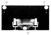
図4は、送気装置11と吸気装置12の配置形態の第一の例を示す。ここに、一つの送気装置11と一つの吸気装置12から組を構成し、一つの気流ガイドアセンブリを構成する。図4に示す構造において、送気装置11による目標空間1の底部における投影及び吸気装置12は、デスク3の同一側に位置するとともに、送気装置11の中心軸線と吸気装置12の中心軸線とが互いに位置合わせされる。
図5は、送気装置11と吸気装置12の配置形態の第二の例を示す。ここに、一つの送気装置11と一つの吸気装置12から組を構成し、送気装置11による目標空間1の底部における投影は、デスク3の一方側に位置するが、吸気装置12は、デスク3の下方に位置し、送気装置11の中心軸線と吸気装置12の中心軸線とが互いにずれる。
図6に示す配置形態の第三の例において、気流ガイドアセンブリを構成するには、二つの送気装置11と一つの吸気装置12とを含む。ここに、二つの送気装置11による目標空間1の底部における投影は、デスク3の両側にそれぞれ位置し、または、それらの投影はデスク3になく、吸気装置12は、デスク3の下方に位置し、各送気装置11の中心軸線と吸気装置12の中心軸線とが互いにずれ、デスク3両側の空間内の汚染物を対応して処理することができる。
図7に示す配置形態の第四の例において、四つの送気装置11と一つの吸気装置12とを含む。四つの送気装置11による目標空間1の底部における投影は、デスク3の四つの側辺の外にそれぞれ位置し、または、それらの投影はデスク3になく、吸気装置12は、デスク3の下方に位置する。従って、該配置形態において、吸気装置12の中心軸線と四つの送気装置11の中心軸線とは互いにずれる。
図8に示す配置形態の第五の例において、一つの送気装置11と二つの吸気装置12とを含む。ここに、対応する目標空間1に二つのデスク3が配置され、二つの吸気装置12は、この二つのデスク3の下方にそれぞれ位置するが、送気装置11による目標空間1の底部における投影は、この二つのデスク3の間に位置する。従って、該配置形態において、送気装置11の中心軸線と二つの吸気装置12の中心軸線とは、それぞれ互いにずれる。この例において、送気装置11として双方向に送気する組み込み型空調端末装置を用いることができる。このように、元の空調システムと互換性があり、気流制御システムの実装難易度をさらに下げることができる。
図9に示す配置形態の第六の例において、一つの送気装置11と四つの吸気装置12とを含む。ここに、対応する目標空間1に四つのデスク3が配置され、四つの吸気装置12は、この四つのデスク3の下方にそれぞれ位置し、送気装置11による目標空間1の底部における投影は、この四つのデスク3の間の空隙に位置する。これにより、該配置形態において、送気装置11の中心軸線と四つの吸気装置12の中心軸線とは、それぞれ互いにずれる。この例において、送気装置11として回りに送気する組み込み型空調端末装置を用いることができる。このように、元の空調システムと互換性があり、気流制御システムの実装難易度をさらに下げることができる。
以上の送気装置11と吸気装置12の配置形態に対する説明において、いくつかの送気装置11と対応して互いに協働するいくつかの吸気装置12とからなるセットを気流ガイドアセンブリに定義する。特定の目標空間1に応用される気流制御システム10について、このように定義される気流ガイドアセンブリを一つ含んでもよく、二つ、三つ以上のこのような気流ガイドアセンブリを含んでもよく、その具体的な数は、設計段階に目標空間1の面積、オフィスの数、オフィススタッフの数などの要素に基づいて決定される。
以下、本発明に係る気流制御システム10の各方面の制御パラメータを説明する。
上記のように、吸気装置12の吸引作用により吸気気流22が形成され、該吸気気流22は、誘導気流23を形成する過程で主要な作用を果たす。誘導気流23を効果的に形成するために、好ましくは、吸気気流22の風速は、吹出気流21の風速よりも大きい。
出願人は、シミュレーション実験により、送気装置11と吸気装置12との設置形態及びサイズのパラメータと吹出気流21及び吸気気流22の流動パラメータとの関係を決定することによって、気流制御システム10に対する設計を指導することができる。ここに、CO2を用いて汚染物を擬似的に示す。
図10は、実験1で得られた目標空間1におけるCO2濃度分布図を示す。該実験1は、図6に示す送気装置11と吸気装置12の配置形態を用い、即ち、二つの送気装置11による目標空間1の底部における投影は、デスク3の両側にそれぞれ位置し、吸気装置12は、デスク3の下方に位置し、且つ、吸気装置12の吸気口は、サイズが300mm×300mmである正方形と仮定される。実験1において、送気装置11の吹出気流21の風速は、約0.3m/sに設定され、吸気装置12の吸気気流22の風速は、約2.1m/sに設定される。該吸気気流22の風速条件では、形成される気流パターンは、図11に示すように、オフィススタッフ2からの吐出気体の上向きの拡散の傾向が抑制されるように、上から下への誘導気流23を基本的に形成できることがわかる。
さらに、図12に示す実験2において、吸気装置12の吸気口のサイズは、200mm×200mmであり、送気装置11の吹出気流21の風速は、約0.5m/sに設定され、吸気気流22の風速は、2.9m/sに設定され、このとき、形成される誘導気流23は、オフィススタッフ2からの吐出気体を効果的に遮断できることがわかる。
また、上述した結果から、同じ送気装置と還気装置のレイアウトで、吸気気流22の風速を高めると、流動速度がやや高い誘導気流が発生でき、流動速度がやや高い誘導気流により、汚染物の上向きの拡散の傾向をよりよく抑制し、汚染物の隔離を効果的に実現できることがわかる。
図13の実験3において、吸気気流22の風速は、1.9m/sに設定され、送気口で、吹出気流21の風速は、1m/sに設定され、このとき、有効な誘導気流23が形成でき、汚染物の上向きの拡散を阻止できるが、全体的な気流抑制の効果は、実験1と実験2より少し劣っており、まとめてみれば、送気装置11は、その送気口での吹出気流21の風速が好ましく1m/s以下であり、形成される誘導気流による汚染物に対する制御効果がよりよく、汚染物をさらに狭い範囲内に制御することができる。
図14に示す実験4において、吸気気流22の風速は、0.5m/sに設定され、吹出気流21の送気口での風速は、0.8m/sに大きくされる。このとき、ある程度誘導気流を形成し、汚染物(図示CO2)の拡散を抑制できるが、狭い範囲内において、向かい合って座っている二人が生成した汚染物の間に一定程度の交差を発生する。従って、誘導気流が汚染物の拡散をより大きく抑制するために、例えば、実験1~3と同じ形態を用い、吹出気流21の風速を吸気気流22の風速よりも小さくすべきである。
さらに、以下の方式によっても誘導気流23による汚染物への拡散抑制効果を保持し、さらに向上させる前提で、消費電力を削減できる。
吸気面積が同じ場合に、吸気口の数を増やすとともに、さらに、複数の吸気口を互いに離間させるように設けることができる。総吸気面積が変わらず、複数の吸気口を設ける場合は、一つの吸気口しかないものよりも、複数の吸気口のそれぞれは、面積が低減され、それぞれの吸気口での風速を適宜に降下させることによって、全体的に必要な総風量を降下させ、消費電力を削減する目的を実現する。
吸気口を矩形、楕円形または類似する長尺形の形状に設けるとともに、該長尺形の形状の長辺側を対応する送気装置11による目標空間1の底部における投影の位置する箇所に対向させる。このように吸気口を設けると、長辺は、障害物の隣に座っているオフィススタッフに対応し、オフィススタッフから吐出される汚染物をよりよく吸入することができる。
例えば、実験(例えば、実験1)に披露されているように、図6に示す送気装置11と吸気装置12の配置形態において、吸気装置12は、一つの正方形の吸気口を含み、このとき、対応する目標空間1における汚染物を抑制するために、必要な吸気量は700m3/hである。
不図示の実験5において、総吸気面積は、実験1に対して変わらないが、二つの矩形で、互いに離間された吸気口を設け、このとき、対応する目標空間1における汚染物を抑制するために、必要な吸気量は520m3/h(各吸気口の吸気量は260m3/hである)である。実験1と実験5の実験データの比較は、以下の表1に示す。

1 目標空間
2 オフィススタッフ
3 デスク
10 気流制御システム
11 送気装置
12 吸気装置
13 送気通路
14 還気通路
15 排気装置
16 アクティブ吸引部材
17 濾過部材
21 吹出気流
22 吸気気流
23 誘導気流
2 オフィススタッフ
3 デスク
10 気流制御システム
11 送気装置
12 吸気装置
13 送気通路
14 還気通路
15 排気装置
16 アクティブ吸引部材
17 濾過部材
21 吹出気流
22 吸気気流
23 誘導気流
Claims (10)
- 頂部と底部とを含む目標空間、における気流方向を制御するための気流制御システムにおいて、
少なくとも一つの気流ガイドアセンブリ、
を含み、
前記気流ガイドアセンブリは、
前記目標空間の前記頂部に位置する送気口を含み、前記送気口を介して前記目標空間へ吹出気流を吹き出す、少なくとも一つの送気装置と、
前記目標空間の前記底部に位置する吸気口を含み、前記吸気口を介して前記目標空間から空気を吸引する、少なくとも一つの吸気装置と、
を含み、
前記少なくとも一つの送気装置から吹き出された吹出気流と、前記少なくとも一つの吸気装置の吸引力と、が互いに協働して、上から下への誘導気流を発生させ、前記目標空間における汚染物が誘導気流の流動経路に位置することにより、前記誘導気流により前記目標空間に存在する汚染物の上向きの拡散を抑制することができる、
ことを特徴とする、気流制御システム。 - 前記吹出気流の風速は、前記吸気装置による作用で形成された吸気気流の風速よりも小さい、
ことを特徴とする、請求項1に記載の気流制御システム。 - 前記少なくとも一つの吸気装置の中心軸線と、前記少なくとも一つの送気装置の中心軸線とは、互いにずれる、
ことを特徴とする、請求項1に記載の気流制御システム。 - 前記気流ガイドアセンブリは、
中心軸線が互いにずれるかまたは重なるように設けられた、一つの前記送気装置と一つの前記吸気装置と、または、
前記吸気装置の両側にそれぞれ一つの前記送気装置を有するような、二つの前記送気装置と一つの前記吸気装置と、または、
一つの前記吸気装置と、前記吸気装置の少なくとも両側に設けられる四つの前記送気装置と、または、
前記送気装置の両側にそれぞれ一つの前記吸気装置を有するような、一つの前記送気装置と二つの前記吸気装置と、または、
一つの前記送気装置と、前記送気装置の少なくとも両側に設けられる四つの前記吸気装置と、
を含む、
ことを特徴とする、請求項1に記載の気流制御システム。 - 前記目標空間に障害物が存在し、
前記送気装置は、前記障害物による前記頂部における投影の範囲の外に位置し、
前記吸気装置は、前記障害物による前記底部における投影の範囲内に位置する、
ことを特徴とする、請求項1~4の何れか1項に記載の気流制御システム。 - 前記送気装置の送気口は、吹出気流を略垂直に吹き出す、
ことを特徴とする、請求項1に記載の気流制御システム。 - 前記吸気装置に吸引された汚染物付きの気流を、外部環境に排出する排気装置、をさらに含む、
ことを特徴とする、請求項1に記載の気流制御システム。 - 前記目標空間に設けられ、前記目標空間から吸引された気流を処理するための空気処理装置、をさらに含む、
ことを特徴とする、請求項1に記載の気流制御システム。 - 前記空気処理装置は、浄化アセンブリを含む、
ことを特徴とする、請求項8に記載の気流制御システム。 - 前記吸気装置には、アクティブ吸引部材が設けられる、
ことを特徴とする、請求項1に記載の気流制御システム。
Applications Claiming Priority (2)
| Application Number | Priority Date | Filing Date | Title |
|---|---|---|---|
| CN202011357661.1A CN114543324B (zh) | 2020-11-27 | 2020-11-27 | 气流控制系统 |
| CN202011357661.1 | 2020-11-27 |
Publications (1)
| Publication Number | Publication Date |
|---|---|
| WO2022114151A1 true WO2022114151A1 (ja) | 2022-06-02 |
Family
ID=81667983
Family Applications (1)
| Application Number | Title | Priority Date | Filing Date |
|---|---|---|---|
| PCT/JP2021/043487 Ceased WO2022114151A1 (ja) | 2020-11-27 | 2021-11-26 | 気流制御システム |
Country Status (2)
| Country | Link |
|---|---|
| CN (1) | CN114543324B (ja) |
| WO (1) | WO2022114151A1 (ja) |
Families Citing this family (1)
| Publication number | Priority date | Publication date | Assignee | Title |
|---|---|---|---|---|
| CN115264710B (zh) * | 2022-07-28 | 2024-11-26 | 杭州良工装饰有限公司 | 一种办公空间系统 |
Citations (11)
| Publication number | Priority date | Publication date | Assignee | Title |
|---|---|---|---|---|
| JPS5025805U (ja) * | 1973-06-30 | 1975-03-25 | ||
| JPH05106348A (ja) * | 1991-10-15 | 1993-04-27 | Sekisui House Ltd | 用途別変更型ベツドルーム兼リビングルーム |
| JPH0538982U (ja) * | 1991-10-24 | 1993-05-25 | 日本電気エンジニアリング株式会社 | ダクト |
| JPH05180464A (ja) * | 1991-12-26 | 1993-07-23 | Hitachi Plant Eng & Constr Co Ltd | 空調システム |
| JPH062904A (ja) * | 1992-06-17 | 1994-01-11 | Aoki Corp | クリーン住宅構造 |
| JPH11311442A (ja) * | 1998-04-27 | 1999-11-09 | Tokyo Electric Power Co Inc:The | 室内の空調装置 |
| JP2000234774A (ja) * | 1999-02-10 | 2000-08-29 | Fuji Kogyo Kk | 室内空気循環装置 |
| JP2011252633A (ja) * | 2010-06-01 | 2011-12-15 | T Hasegawa Co Ltd | におい除去システム |
| WO2013021466A1 (ja) * | 2011-08-09 | 2013-02-14 | 日本たばこ産業株式会社 | 喫煙室の換気方法 |
| JP2015218956A (ja) * | 2014-05-19 | 2015-12-07 | 三菱電機ビルテクノサービス株式会社 | 空調システム |
| CN210399298U (zh) * | 2019-07-04 | 2020-04-24 | 苏州智允机电系统集成科技有限公司 | 一种无尘车间 |
Family Cites Families (7)
| Publication number | Priority date | Publication date | Assignee | Title |
|---|---|---|---|---|
| CN101982704B (zh) * | 2010-10-12 | 2013-07-03 | 中国矿业大学 | 建筑物大空间公共场所有害物质的防护系统及方法 |
| JP2017161165A (ja) * | 2016-03-09 | 2017-09-14 | パナソニックIpマネジメント株式会社 | 気流制御システム、およびこれを備えたブース |
| CN106178706B (zh) * | 2016-07-06 | 2018-11-13 | 苏州艾尔新净化科技有限公司 | 气流均衡的空气净化系统 |
| CN206701907U (zh) * | 2017-04-26 | 2017-12-05 | 刘自仙 | 一种新型通风柜 |
| CN109751725A (zh) * | 2018-12-29 | 2019-05-14 | 青岛海尔空调电子有限公司 | 用于新风系统的控制方法、新风系统 |
| CN111365836A (zh) * | 2020-03-17 | 2020-07-03 | 武汉东昌仓贮技术有限公司 | 一种空调风口布置与管道内部病菌的机械消除方法 |
| CN111486529B (zh) * | 2020-03-25 | 2021-03-30 | 西安建筑科技大学 | 一种病原微生物防控病区空气定向传输装置及空气消杀系统 |
-
2020
- 2020-11-27 CN CN202011357661.1A patent/CN114543324B/zh active Active
-
2021
- 2021-11-26 WO PCT/JP2021/043487 patent/WO2022114151A1/ja not_active Ceased
Patent Citations (11)
| Publication number | Priority date | Publication date | Assignee | Title |
|---|---|---|---|---|
| JPS5025805U (ja) * | 1973-06-30 | 1975-03-25 | ||
| JPH05106348A (ja) * | 1991-10-15 | 1993-04-27 | Sekisui House Ltd | 用途別変更型ベツドルーム兼リビングルーム |
| JPH0538982U (ja) * | 1991-10-24 | 1993-05-25 | 日本電気エンジニアリング株式会社 | ダクト |
| JPH05180464A (ja) * | 1991-12-26 | 1993-07-23 | Hitachi Plant Eng & Constr Co Ltd | 空調システム |
| JPH062904A (ja) * | 1992-06-17 | 1994-01-11 | Aoki Corp | クリーン住宅構造 |
| JPH11311442A (ja) * | 1998-04-27 | 1999-11-09 | Tokyo Electric Power Co Inc:The | 室内の空調装置 |
| JP2000234774A (ja) * | 1999-02-10 | 2000-08-29 | Fuji Kogyo Kk | 室内空気循環装置 |
| JP2011252633A (ja) * | 2010-06-01 | 2011-12-15 | T Hasegawa Co Ltd | におい除去システム |
| WO2013021466A1 (ja) * | 2011-08-09 | 2013-02-14 | 日本たばこ産業株式会社 | 喫煙室の換気方法 |
| JP2015218956A (ja) * | 2014-05-19 | 2015-12-07 | 三菱電機ビルテクノサービス株式会社 | 空調システム |
| CN210399298U (zh) * | 2019-07-04 | 2020-04-24 | 苏州智允机电系统集成科技有限公司 | 一种无尘车间 |
Also Published As
| Publication number | Publication date |
|---|---|
| CN114543324A (zh) | 2022-05-27 |
| CN114543324B (zh) | 2024-12-31 |
Similar Documents
| Publication | Publication Date | Title |
|---|---|---|
| EP1146841B1 (en) | Method and device for ventilating a so called clean room | |
| US10357810B2 (en) | Steady flow structure and a ventilation apparatus having said steady flow structure | |
| JP7627825B2 (ja) | 気流環境システム | |
| WO2022114151A1 (ja) | 気流制御システム | |
| US12535235B2 (en) | Apparatus, system, and method for preventing spread of air-borne contaminants | |
| JPH01179841A (ja) | 流体処理装置 | |
| WO2022114148A1 (ja) | 汚染物制御システム、還気装置及びその制御方法 | |
| JP2018135765A (ja) | 送風装置および空気清浄機能付送風装置 | |
| US20210348784A1 (en) | Breathing zone ventillation system | |
| US20220316727A1 (en) | Air-circulating conference table | |
| JP7847290B2 (ja) | 個室ブース | |
| US20220333797A1 (en) | System for creating a microenvironment within an ambient environment | |
| JP2006317048A (ja) | クリーンルーム | |
| WO2022114149A1 (ja) | 空気浄化装置及び該空気浄化装置を含む空気浄化システム | |
| JP5991570B2 (ja) | 空調システム | |
| JP2023019220A (ja) | 屋内雰囲気浄化システム | |
| WO2022190499A1 (ja) | 気流環境システム | |
| JP7675303B2 (ja) | 送風装置、送風装置を備えた個室型ブース | |
| JP2023012981A (ja) | 送風装置 | |
| JP7386387B2 (ja) | 送風装置 | |
| WO2024122147A1 (ja) | 送風システム | |
| JP2024016717A (ja) | プッシュ型送風装置及びそれを用いた空間分離装置 | |
| JP2022162440A (ja) | 空気清浄装置 | |
| JP2023174430A (ja) | 送風装置 | |
| KR200388990Y1 (ko) | 실내형 공기정화기 |
Legal Events
| Date | Code | Title | Description |
|---|---|---|---|
| 121 | Ep: the epo has been informed by wipo that ep was designated in this application |
Ref document number: 21898123 Country of ref document: EP Kind code of ref document: A1 |
|
| NENP | Non-entry into the national phase |
Ref country code: DE |
|
| 122 | Ep: pct application non-entry in european phase |
Ref document number: 21898123 Country of ref document: EP Kind code of ref document: A1 |
|
| NENP | Non-entry into the national phase |
Ref country code: JP |